EP4475296A1 - Cap assembly, battery, battery module, battery pack, and vehicle - Google Patents
Cap assembly, battery, battery module, battery pack, and vehicle Download PDFInfo
- Publication number
- EP4475296A1 EP4475296A1 EP22949032.1A EP22949032A EP4475296A1 EP 4475296 A1 EP4475296 A1 EP 4475296A1 EP 22949032 A EP22949032 A EP 22949032A EP 4475296 A1 EP4475296 A1 EP 4475296A1
- Authority
- EP
- European Patent Office
- Prior art keywords
- battery
- cell
- housing
- cap assembly
- busbar plate
- Prior art date
- Legal status (The legal status is an assumption and is not a legal conclusion. Google has not performed a legal analysis and makes no representation as to the accuracy of the status listed.)
- Pending
Links
Images




Classifications
-
- H—ELECTRICITY
- H01—ELECTRIC ELEMENTS
- H01M—PROCESSES OR MEANS, e.g. BATTERIES, FOR THE DIRECT CONVERSION OF CHEMICAL ENERGY INTO ELECTRICAL ENERGY
- H01M50/00—Constructional details or processes of manufacture of the non-active parts of electrochemical cells other than fuel cells, e.g. hybrid cells
- H01M50/20—Mountings; Secondary casings or frames; Racks, modules or packs; Suspension devices; Shock absorbers; Transport or carrying devices; Holders
- H01M50/249—Mountings; Secondary casings or frames; Racks, modules or packs; Suspension devices; Shock absorbers; Transport or carrying devices; Holders specially adapted for aircraft or vehicles, e.g. cars or trains
-
- H—ELECTRICITY
- H01—ELECTRIC ELEMENTS
- H01M—PROCESSES OR MEANS, e.g. BATTERIES, FOR THE DIRECT CONVERSION OF CHEMICAL ENERGY INTO ELECTRICAL ENERGY
- H01M50/00—Constructional details or processes of manufacture of the non-active parts of electrochemical cells other than fuel cells, e.g. hybrid cells
- H01M50/50—Current conducting connections for cells or batteries
- H01M50/572—Means for preventing undesired use or discharge
- H01M50/584—Means for preventing undesired use or discharge for preventing incorrect connections inside or outside the batteries
- H01M50/588—Means for preventing undesired use or discharge for preventing incorrect connections inside or outside the batteries outside the batteries, e.g. incorrect connections of terminals or busbars
-
- H—ELECTRICITY
- H01—ELECTRIC ELEMENTS
- H01M—PROCESSES OR MEANS, e.g. BATTERIES, FOR THE DIRECT CONVERSION OF CHEMICAL ENERGY INTO ELECTRICAL ENERGY
- H01M10/00—Secondary cells; Manufacture thereof
- H01M10/04—Construction or manufacture in general
- H01M10/045—Cells or batteries with folded plate-like electrodes
-
- H—ELECTRICITY
- H01—ELECTRIC ELEMENTS
- H01M—PROCESSES OR MEANS, e.g. BATTERIES, FOR THE DIRECT CONVERSION OF CHEMICAL ENERGY INTO ELECTRICAL ENERGY
- H01M50/00—Constructional details or processes of manufacture of the non-active parts of electrochemical cells other than fuel cells, e.g. hybrid cells
- H01M50/10—Primary casings; Jackets or wrappings
- H01M50/102—Primary casings; Jackets or wrappings characterised by their shape or physical structure
- H01M50/107—Primary casings; Jackets or wrappings characterised by their shape or physical structure having curved cross-section, e.g. round or elliptic
-
- H—ELECTRICITY
- H01—ELECTRIC ELEMENTS
- H01M—PROCESSES OR MEANS, e.g. BATTERIES, FOR THE DIRECT CONVERSION OF CHEMICAL ENERGY INTO ELECTRICAL ENERGY
- H01M50/00—Constructional details or processes of manufacture of the non-active parts of electrochemical cells other than fuel cells, e.g. hybrid cells
- H01M50/10—Primary casings; Jackets or wrappings
- H01M50/147—Lids or covers
- H01M50/148—Lids or covers characterised by their shape
- H01M50/152—Lids or covers characterised by their shape for cells having curved cross-section, e.g. round or elliptic
-
- H—ELECTRICITY
- H01—ELECTRIC ELEMENTS
- H01M—PROCESSES OR MEANS, e.g. BATTERIES, FOR THE DIRECT CONVERSION OF CHEMICAL ENERGY INTO ELECTRICAL ENERGY
- H01M50/00—Constructional details or processes of manufacture of the non-active parts of electrochemical cells other than fuel cells, e.g. hybrid cells
- H01M50/10—Primary casings; Jackets or wrappings
- H01M50/147—Lids or covers
- H01M50/166—Lids or covers characterised by the methods of assembling casings with lids
- H01M50/169—Lids or covers characterised by the methods of assembling casings with lids by welding, brazing or soldering
-
- H—ELECTRICITY
- H01—ELECTRIC ELEMENTS
- H01M—PROCESSES OR MEANS, e.g. BATTERIES, FOR THE DIRECT CONVERSION OF CHEMICAL ENERGY INTO ELECTRICAL ENERGY
- H01M50/00—Constructional details or processes of manufacture of the non-active parts of electrochemical cells other than fuel cells, e.g. hybrid cells
- H01M50/10—Primary casings; Jackets or wrappings
- H01M50/172—Arrangements of electric connectors penetrating the casing
- H01M50/174—Arrangements of electric connectors penetrating the casing adapted for the shape of the cells
- H01M50/179—Arrangements of electric connectors penetrating the casing adapted for the shape of the cells for cells having curved cross-section, e.g. round or elliptic
-
- H—ELECTRICITY
- H01—ELECTRIC ELEMENTS
- H01M—PROCESSES OR MEANS, e.g. BATTERIES, FOR THE DIRECT CONVERSION OF CHEMICAL ENERGY INTO ELECTRICAL ENERGY
- H01M50/00—Constructional details or processes of manufacture of the non-active parts of electrochemical cells other than fuel cells, e.g. hybrid cells
- H01M50/10—Primary casings; Jackets or wrappings
- H01M50/183—Sealing members
- H01M50/186—Sealing members characterised by the disposition of the sealing members
- H01M50/188—Sealing members characterised by the disposition of the sealing members the sealing members being arranged between the lid and terminal
-
- H—ELECTRICITY
- H01—ELECTRIC ELEMENTS
- H01M—PROCESSES OR MEANS, e.g. BATTERIES, FOR THE DIRECT CONVERSION OF CHEMICAL ENERGY INTO ELECTRICAL ENERGY
- H01M50/00—Constructional details or processes of manufacture of the non-active parts of electrochemical cells other than fuel cells, e.g. hybrid cells
- H01M50/20—Mountings; Secondary casings or frames; Racks, modules or packs; Suspension devices; Shock absorbers; Transport or carrying devices; Holders
- H01M50/204—Racks, modules or packs for multiple batteries or multiple cells
- H01M50/207—Racks, modules or packs for multiple batteries or multiple cells characterised by their shape
- H01M50/213—Racks, modules or packs for multiple batteries or multiple cells characterised by their shape adapted for cells having curved cross-section, e.g. round or elliptic
-
- H—ELECTRICITY
- H01—ELECTRIC ELEMENTS
- H01M—PROCESSES OR MEANS, e.g. BATTERIES, FOR THE DIRECT CONVERSION OF CHEMICAL ENERGY INTO ELECTRICAL ENERGY
- H01M50/00—Constructional details or processes of manufacture of the non-active parts of electrochemical cells other than fuel cells, e.g. hybrid cells
- H01M50/30—Arrangements for facilitating escape of gases
- H01M50/342—Non-re-sealable arrangements
- H01M50/3425—Non-re-sealable arrangements in the form of rupturable membranes or weakened parts, e.g. pierced with the aid of a sharp member
-
- H—ELECTRICITY
- H01—ELECTRIC ELEMENTS
- H01M—PROCESSES OR MEANS, e.g. BATTERIES, FOR THE DIRECT CONVERSION OF CHEMICAL ENERGY INTO ELECTRICAL ENERGY
- H01M50/00—Constructional details or processes of manufacture of the non-active parts of electrochemical cells other than fuel cells, e.g. hybrid cells
- H01M50/50—Current conducting connections for cells or batteries
- H01M50/502—Interconnectors for connecting terminals of adjacent batteries; Interconnectors for connecting cells outside a battery casing
- H01M50/505—Interconnectors for connecting terminals of adjacent batteries; Interconnectors for connecting cells outside a battery casing comprising a single busbar
-
- H—ELECTRICITY
- H01—ELECTRIC ELEMENTS
- H01M—PROCESSES OR MEANS, e.g. BATTERIES, FOR THE DIRECT CONVERSION OF CHEMICAL ENERGY INTO ELECTRICAL ENERGY
- H01M50/00—Constructional details or processes of manufacture of the non-active parts of electrochemical cells other than fuel cells, e.g. hybrid cells
- H01M50/50—Current conducting connections for cells or batteries
- H01M50/528—Fixed electrical connections, i.e. not intended for disconnection
-
- H—ELECTRICITY
- H01—ELECTRIC ELEMENTS
- H01M—PROCESSES OR MEANS, e.g. BATTERIES, FOR THE DIRECT CONVERSION OF CHEMICAL ENERGY INTO ELECTRICAL ENERGY
- H01M50/00—Constructional details or processes of manufacture of the non-active parts of electrochemical cells other than fuel cells, e.g. hybrid cells
- H01M50/50—Current conducting connections for cells or batteries
- H01M50/531—Electrode connections inside a battery casing
-
- H—ELECTRICITY
- H01—ELECTRIC ELEMENTS
- H01M—PROCESSES OR MEANS, e.g. BATTERIES, FOR THE DIRECT CONVERSION OF CHEMICAL ENERGY INTO ELECTRICAL ENERGY
- H01M50/00—Constructional details or processes of manufacture of the non-active parts of electrochemical cells other than fuel cells, e.g. hybrid cells
- H01M50/50—Current conducting connections for cells or batteries
- H01M50/572—Means for preventing undesired use or discharge
- H01M50/584—Means for preventing undesired use or discharge for preventing incorrect connections inside or outside the batteries
- H01M50/586—Means for preventing undesired use or discharge for preventing incorrect connections inside or outside the batteries inside the batteries, e.g. incorrect connections of electrodes
-
- H—ELECTRICITY
- H01—ELECTRIC ELEMENTS
- H01M—PROCESSES OR MEANS, e.g. BATTERIES, FOR THE DIRECT CONVERSION OF CHEMICAL ENERGY INTO ELECTRICAL ENERGY
- H01M50/00—Constructional details or processes of manufacture of the non-active parts of electrochemical cells other than fuel cells, e.g. hybrid cells
- H01M50/50—Current conducting connections for cells or batteries
- H01M50/572—Means for preventing undesired use or discharge
- H01M50/584—Means for preventing undesired use or discharge for preventing incorrect connections inside or outside the batteries
- H01M50/59—Means for preventing undesired use or discharge for preventing incorrect connections inside or outside the batteries characterised by the protection means
- H01M50/593—Spacers; Insulating plates
-
- H—ELECTRICITY
- H01—ELECTRIC ELEMENTS
- H01M—PROCESSES OR MEANS, e.g. BATTERIES, FOR THE DIRECT CONVERSION OF CHEMICAL ENERGY INTO ELECTRICAL ENERGY
- H01M2220/00—Batteries for particular applications
- H01M2220/20—Batteries in motive systems, e.g. vehicle, ship, plane
-
- Y—GENERAL TAGGING OF NEW TECHNOLOGICAL DEVELOPMENTS; GENERAL TAGGING OF CROSS-SECTIONAL TECHNOLOGIES SPANNING OVER SEVERAL SECTIONS OF THE IPC; TECHNICAL SUBJECTS COVERED BY FORMER USPC CROSS-REFERENCE ART COLLECTIONS [XRACs] AND DIGESTS
- Y02—TECHNOLOGIES OR APPLICATIONS FOR MITIGATION OR ADAPTATION AGAINST CLIMATE CHANGE
- Y02E—REDUCTION OF GREENHOUSE GAS [GHG] EMISSIONS, RELATED TO ENERGY GENERATION, TRANSMISSION OR DISTRIBUTION
- Y02E60/00—Enabling technologies; Technologies with a potential or indirect contribution to GHG emissions mitigation
- Y02E60/10—Energy storage using batteries
Definitions
- the present disclosure relates to the technology field of batteries, and in particular, to a cap assembly, a battery, a battery module, a battery pack, and a vehicle.
- Batteries are widely used in life. Batteries in related technologies mainly include cells, a battery housing and a cap assembly. The cells are placed in the battery housing, and tabs of the cells are bent and gathered together and then connected to the cap assembly, thereby achieving electrical connection between the cap assembly and the cells, and sealing the battery housing.
- the cap assembly in related technologies has a complex structure and poor stability, which affects the service life of the battery.
- the present disclosure provides a cap assembly, which is able to cover a busbar plate through an isolation portion arranged on a plastic pad, thereby providing a protection effect on the busbar plate, preventing the busbar plate from contacting a housing, improving the pressure resistance of the entire battery, ensuring structural stability, and prolonging the service life of the battery.
- an embodiment of the present disclosure provides a cap assembly applied to a battery.
- the battery includes a cell and a housing for accommodating the cell.
- the cap assembly includes:
- an end surface of the isolation portion away from the cell is provided with a chamfer.
- an angle of the chamfer is less than or equal to 60°.
- the isolation portion and the plastic pad form a receiving groove for receiving the busbar plate; where a side wall of the receiving groove is attached to at least a part of a side wall of the busbar plate; and at least a part of a bottom of the receiving groove is in contact with a top surface of the busbar plate.
- a depth of the receiving groove is adapted to a thickness of the busbar plate.
- a diameter of the receiving groove is adapted to a diameter of the busbar plate.
- the present disclosure provides a battery.
- the cap assembly as described above, the voltage resistance of the entire battery is improved, the structural stability is ensured, and the service life of the battery is prolonged.
- an embodiment of the present disclosure provides a battery which includes a cell, a housing, and a cap assembly as described above.
- the housing is configured to accommodate the cell, and the cap assembly is respectively connected to the cell and the housing.
- the present disclosure provides a battery module.
- the voltage resistance of the entire battery is improved, the structural stability is ensured, and the service life of the battery is prolonged.
- an embodiment of the present disclosure provides a battery module which includes a plurality of batteries as described above.
- the plurality of batteries are arranged in multiple rows and multiple columns.
- the present disclosure provides a battery pack.
- an embodiment of the present disclosure provides a battery pack which includes a box and the battery module as described above.
- the battery module is provided in the box.
- the present disclosure provides a vehicle.
- the battery pack as described above the voltage resistance of the entire battery is improved, the structural stability is ensured, and the service life of the battery is prolonged.
- an embodiment of the present disclosure provides a vehicle which includes a vehicle body and the battery pack as described above.
- the battery pack is provided in the vehicle body.
- the present disclosure provides a cap assembly, a battery, a battery module, a battery pack and a vehicle, which is able to cover a busbar plate through an isolation portion arranged on a plastic pad, thereby providing a protection effect on the busbar plate, preventing the busbar plate from contacting a housing, improving the pressure resistance of the entire battery, ensuring structural stability, and prolonging the service life of the battery.
- the present disclosure has a simple structure and is convenient to assemble and disassemble, can improve the voltage resistance of the entire battery, ensure structural stability, and prolong the service life of the battery.
- the terms “mounted”, “connected with”, and “fixed” should be interpreted broadly, and may be, for example, fixed connections, detachable connections, or integral connections; it may be mechanical or electrical connections; it may also be direct connections or indirect connections via intervening structures; it may also be inner communications of two elements or interaction relationships between two elements.
- the specific meanings of the above terms in the present disclosure can be understood by one of ordinary skill in the art according to specific situations.
- a first feature is “on” or “under” a second feature may include an embodiment in which the first feature is in direct contact with the second feature, or may also include an embodiment in which the first feature and the second feature are not in direct contact with each other, but are contacted via another feature formed therebetween.
- a first feature is "on”, “above”, or “on top of” a second feature may include an embodiment in which the first feature is right or obliquely “on”, “above”, or “on top of” the second feature, or just means that the first feature is at a height higher than that of the second feature.
- a first feature is "below”, “under”, or “on bottom of” a second feature may include an embodiment in which the first feature is right or obliquely “below”, “under”, or “on bottom of” the second feature, or just means that the first feature is at a height lower than that of the second feature.
- orientations or positional relationships indicated by the terms “center”, “longitudinal”, “transverse”, “length”, “width”, “thickness”, “upper”, “lower”, “front”, “rear”, “left”, “right”, “vertical”, “horizontal”, “top”, “bottom”, “inner”, “outer”, “clockwise”, “counterclockwise”, “axial”, “radial”, “circumferential”, and the like are based on the orientations or positional relationships shown in the accompanying drawings. It is merely for the convenience of describing the present disclosure and simplifying the description, rather than indicating or implying that the indicated device or element must have a specific orientation, be constructed and operated in a specific orientation, and therefore should not be understood as a limitation on the present disclosure.
- a plurality of means two or more.
- first and second are only used for distinguishing in description, and do not have a special meaning.
- first position and second position mean two different positions.
- the present embodiment provides a vehicle, which includes a vehicle body and a battery pack.
- the battery pack is provided in the vehicle body, and supplies electric power to the vehicle body to drive the vehicle body to move.
- the battery pack includes a box and a battery module.
- the battery module is provided in the box, that is, the battery module is fixed and protected by the box.
- the battery module in order to increase the maximum amount of electricity that can be stored in the entire battery module as far as possible, as shown in FIG. 1 , the battery module includes a plurality of batteries 1, and the plurality of batteries 1 are arranged in multiple rows and multiple columns. The number and the specific arrangement manner of the batteries 1 may be adjusted according to actual situations, which is not limited in this embodiment.
- the battery includes a cell 13, a housing 12 and a cap assembly 11.
- the housing 12 is configured to accommodate the cell 13.
- the cap assembly 11 is respectively connected to the cell 13 and the housing 12.
- the cap assembly 11 includes a cover plate 111, a busbar plate 112 and a terminal 113.
- the cover plate 111 is arranged at a bottom end of the housing 12 and is connected to a second electrode tab 132 of the cell 13.
- the busbar plate 112 is attached to a top end of the cell 13, so as to be connected to a first electrode tab 131 of the cell 13.
- the terminal 113 penetrates a top end of the housing 12 and is electrically coupled to the busbar plate 112, and a gap exists between a top end of the busbar plate 112 and a bottom end of the terminal 113.
- the first electrode tab 131 is a positive electrode tab
- the second electrode tab 132 is a negative electrode tab.
- friction and collision can be avoided during assembly and use by leaving a gap between the busbar plate 112 and the terminal 113, thereby ensuring the working performance and service life of the battery 1 as far as possible, and minimizing the number of components required for the cap assembly 11 as far as possible, saving manufacturing costs and reducing assembly and disassembly processes.
- the cap assembly 11 can avoid friction and collision during assembly and use, thereby ensuring the working performance and service life of the battery 1 as much as possible, and minimizing the number of components required for the cap assembly 11 as much as possible, saving manufacturing costs and reducing assembly and disassembly processes.
- the cap assembly 11 further includes an energy absorption structure 114.
- the energy absorption structure 114 is connected to the terminal 113, the housing 12 and the busbar plate 112 respectively, and the energy absorption structure 114 is configured to create a gap between the top end of the busbar plate 112 and the bottom end of the terminal 113.
- By providing the energy absorption structure 114 it can provide shock absorption and buffering effects among the terminal 113, the housing 12 and the busbar plate 112, thereby enhancing the ability of shock resistance and impact resistance of the battery 1, and prolonging the service life of the entire battery 1.
- the energy absorption structure 114 includes a sealing ring 1141 and a plastic pad 1142.
- the sealing ring 1141 is arranged between the housing 12 and the terminal 113.
- the plastic pad 1142 is arranged between the housing 12 and the busbar plate 112.
- the sealing ring 1141 penetrates through the plastic pad 1142.
- sealing between the terminal 113 and the housing 12 can be achieved, thereby ensuring the use safety of the cap assembly 11.
- a gap is formed between the top end of the busbar plate 112 and the bottom end of the terminal 113 by cooperation of the sealing ring 1141 and the plastic pad 1142.
- the material of the sealing ring 1141 may be rubber resistant to electrolyte or elastic plastic resistant to electrolyte.
- surfaces of the plastic pad 1142 is provided concavely and convexly to absorb stress generated when the plastic pad 1142 swells, reduce a pressure applied by the stress to the cell 13 and the housing 12, and absorb a pressure generated when the cell 13 expands due to charging.
- a top surface of the plastic pad 1142 is provided with a plurality of first annular grooves 11421.
- the plurality of first annular grooves 11421 are equidistantly distributed along a radial direction, so as to improve the shock absorption and buffering effects of the entire energy absorption structure 114.
- a bottom surface of the plastic pad 1142 is provided with a plurality of second annular grooves 11422.
- the plurality of second annular grooves 11422 are equidistantly distributed along the radial direction.
- the stress generated by the plastic pad 1142 during swelling can be absorbed by the first annular groove 11421 and the second annular groove 11422, so as to reduce the pressure of the stress applied to the cell 13 and the housing 12.
- the pressure caused by the expansion of the cell 13 can also be absorbed by the first annular groove 11421 and the second annular groove 11422.
- first annular grooves 11421 and the second annular grooves 11422 are distributed in a staggered manner, so that the surfaces of the plastic pad 1142 is uneven, thereby further enhancing the shock absorption and buffering effects of the entire plastic pad 1142.
- an edge of the plastic pad 1142 extends in a direction close to the busbar plate 112 to form an isolation portion 11423, and the plastic pad 1142 can cover the busbar plate 112 through the isolation portion 11423.
- One side of the isolation portion 11423 away from the busbar plate 112 is fit with an inner wall of the housing 12, that is, a side peripheral wall of the busbar plate 112 is separated from the inner wall of the housing 12 through the isolation portion 11423, so as to avoid direct contact between the busbar plate 112 and the housing 12, thereby improving the pressure resistance of the entire battery 1.
- the busbar plate 112 is made of aluminum.
- an end surface of the isolation portion 11423 away from the cell 13 is provided with a chamfer, that is, the stress is dispersed through the chamfer, so as to prolong the service life of the plastic pad 11423.
- an angle of the chamfer is less than or equal to 60°.
- the isolation portion 11423 and the plastic pad 1142 form a receiving groove for receiving the busbar plate 112.
- a side wall of the receiving groove is fit with at least a part of a side wall of the busbar plate 112, and at least a part of a bottom of the receiving groove is in contact with a top surface of the busbar plate 112.
- a depth of the receiving groove is adapted to a thickness of the busbar plate 112
- a diameter of the receiving groove is adapted to a diameter of the busbar plate 112, so that all surfaces of the busbar plate 112 except those in contact with the cell 13 can be attached to the receiving groove, thereby preventing the busbar plate 112 from moving in the receiving groove and causing unnecessary abrasion.
- the cover plate 111 is provided with welding portions 1111 and explosion-proof valves 1112.
- the welding portion 1111 protrudes relative to the cover plate 111 in a direction close to the cell 13, and the explosion-proof valve 1112 protrudes relative to the cover plate 111 in a direction away from the cell 13. That is, the welding portion 1111 is welded to a second electrode tab 132 of the cell 13, and the explosion-proof valve 1112 performs an explosion-proof function on the cell 13.
- the explosion-proof valve 1112 protrudes relative to the cover plate 111 in a direction away from the cell 13, that is, a top surface of the cover plate 111 is spaced from a bottom surface of the second electrode tab 132 by a distance h1, and a bottom surface of the explosion-proof valve 1112 is spaced from the bottom surface of the second electrode tab 132 by a distance h2, thus, it can be seen that h2>h1>0, and thus the force generated when the cell 13 expands can be absorbed by h1, and a height difference between h2 and h1 can be used to collect explosion gas, while ensuring the stable connection between the cover plate 111 and the second electrode tab 132, avoiding the spontaneous combustion and explosion of the battery 1 due to excessive internal pressure, thereby improving the safety of the battery 1.
- the width of the explosion-proof valve 1112 is less than half of the radius of the housing 12, so as to reduce the exhaust space required for the entire battery module as far as possible.
- the explosion-proof valve 1112 is provided with an explosion-proof notch 11121.
- the explosion-proof notch 11121 is formed by stamping, so that when an internal pressure of the battery 1 is excessively high, the gas in the housing 12 can be released along the explosion-proof notch 11121, thereby reducing the damage to the periphery of the battery 1 caused by the gas release.
- a plurality of welding portions 1111 are provided, and the plurality of welding portions 1111 are annularly arranged on the cover plate 111, so as to ensure the stability of the connection with the second electrode tab 132. In an embodiment, three welding portions 1111 are provided.
- the welding portion 1111 is in an arc-shaped, and an optimal arc length of the welding portion 1111 is greater than half of a radius of the cell 13, so as to ensure a maximum contact area between the cell 13 and the cover plate 111 as far as possible, thereby improving stability of electrical connection between the cell 13 and the cover plate 111.
- the welding portion 1111 may also be in other shapes, as long as the welding portion 1111 and the second electrode tab 132 can be stably welded, which is not limited in this embodiment.
- a plurality of explosion-proof valves 1112 are provided, and the plurality of explosion-proof valves 1112 are respectively annularly arranged on the cover plate 111, so as to improve the explosion-proof performance.
- three explosion-proof valve 1112 are provided.
- the welding portions 1111 and the explosion-proof valves 1112 are distributed in a staggered manner, so as to ensure that the force applied to the entire cover plate 111 is balanced, thereby improving gas flowability inside the housing 12.
- the cover plate 111 is further provided with a liquid injection hole 1114 for liquid injection or gap exhaust.
- the liquid injection hole 1114 coincides with an axis of the cell 13, that is, the liquid injection hole 1114 is arranged at a center of the cover plate 111, so as to ensure the force on the entire cover plate 111 is balanced.
- the cover plate 111 protrudes along an edge of the liquid injection hole 1114 in a direction close to the cell 13 to form a liquid injection boss, thereby further increasing structural strength of the middle portion of the cover plate 111.
- the peripheral edge of the cover plate 111 is provided with a limiting portion 1113.
- the limiting portion 1113 protrudes with respect to the cover plate 111 in a direction close to the cell 13 to surround the second electrode tab 132. That is, the second electrode tab 132 is positioned through the limiting portion 1113, so that the strength of the entire cover plate 111 can be enhanced, and it can also facilitate accurate welding between the second electrode tab 132 and the welding portion 1111 in the future, so as to avoid the second electrode tab 132 being displaced by force during welding, which may cause the second electrode tab 132 to be close to the inner wall of the housing 12, resulting in a poor welding and a poor performance of the use of the cell 13.
- the limiting portion 1113 can surround the second electrode tab 132, damage of the second electrode tab 132 may also be avoided when assembling the cell 13.
- a surface of the limiting portion 1113 in contact with the second electrode tab 132 is inclined, that is, a cross section of the limiting portion 113 gradually decreases in a direction from the second electrode tab 132 to the first electrode tab 131, so as to further improve a restraint capability of the second electrode tab 132, and minimize the occurrence of displacement of the second electrode tab 132 as far as possible.
- a first chamfer may be provided on the housing 12 along the edge of the opening, and a corresponding second chamfer is provided on the cover plate 111.
- a welding bead 15 can be formed at the connection between the housing 12 and the cover plate 111, which not only facilitates welding and reduces stress concentration, but also further improves stability of the connection between the cover plate 111 and the housing 12.
- the present embodiment provides a vehicle 10, which includes a vehicle body 102 and a battery pack 101.
- the battery pack 101 is arranged in the vehicle body 102, and supplies electric power to the vehicle body 102 to drive the vehicle body to move.
- the battery pack 101 includes a box 1012 and a battery module 1011.
- the battery module 1011 is arranged in the box 1012, and the battery module 1011 is fixed and protected by means of the box 1012.
Landscapes
- Chemical & Material Sciences (AREA)
- Chemical Kinetics & Catalysis (AREA)
- Electrochemistry (AREA)
- General Chemical & Material Sciences (AREA)
- Engineering & Computer Science (AREA)
- Aviation & Aerospace Engineering (AREA)
- Manufacturing & Machinery (AREA)
- Battery Mounting, Suspending (AREA)
- Connection Of Batteries Or Terminals (AREA)
Abstract
Description
- The present disclosure claims priority to
Chinese Patent Application No. 202221650525.6, filed to the Chinese Patent Office on June 28, 2022 - The present disclosure relates to the technology field of batteries, and in particular, to a cap assembly, a battery, a battery module, a battery pack, and a vehicle.
- Batteries are widely used in life. Batteries in related technologies mainly include cells, a battery housing and a cap assembly. The cells are placed in the battery housing, and tabs of the cells are bent and gathered together and then connected to the cap assembly, thereby achieving electrical connection between the cap assembly and the cells, and sealing the battery housing. However, the cap assembly in related technologies has a complex structure and poor stability, which affects the service life of the battery.
- The present disclosure provides a cap assembly, which is able to cover a busbar plate through an isolation portion arranged on a plastic pad, thereby providing a protection effect on the busbar plate, preventing the busbar plate from contacting a housing, improving the pressure resistance of the entire battery, ensuring structural stability, and prolonging the service life of the battery.
- In a first aspect, an embodiment of the present disclosure provides a cap assembly applied to a battery. The battery includes a cell and a housing for accommodating the cell. The cap assembly includes:
- a busbar plate arranged in the housing and attached to a top of the cell so as to be connected to the cell; and
- a plastic pad arranged between the housing and the busbar plate, where an edge of the plastic pad extends in a direction close to the busbar plate to form an isolation portion; the plastic pad is able to cover the busbar plate through the isolation portion, and the isolation portion is able to be fit with an inner wall of the housing.
- In an embodiment, an end surface of the isolation portion away from the cell is provided with a chamfer.
- In an embodiment, an angle of the chamfer is less than or equal to 60°.
- In an embodiment, the isolation portion and the plastic pad form a receiving groove for receiving the busbar plate; where a side wall of the receiving groove is attached to at least a part of a side wall of the busbar plate; and at least a part of a bottom of the receiving groove is in contact with a top surface of the busbar plate.
- In an embodiment, a depth of the receiving groove is adapted to a thickness of the busbar plate.
- In an embodiment, a diameter of the receiving groove is adapted to a diameter of the busbar plate.
- The present disclosure provides a battery. By applying the cap assembly as described above, the voltage resistance of the entire battery is improved, the structural stability is ensured, and the service life of the battery is prolonged.
- In a second aspect, an embodiment of the present disclosure provides a battery which includes a cell, a housing, and a cap assembly as described above. The housing is configured to accommodate the cell, and the cap assembly is respectively connected to the cell and the housing.
- The present disclosure provides a battery module. By applying the battery as described above, the voltage resistance of the entire battery is improved, the structural stability is ensured, and the service life of the battery is prolonged.
- In a third aspect, an embodiment of the present disclosure provides a battery module which includes a plurality of batteries as described above. The plurality of batteries are arranged in multiple rows and multiple columns.
- The present disclosure provides a battery pack. By applying the battery module as described above, the voltage resistance of the entire battery is improved, the structural stability is ensured, and the service life of the battery is prolonged.
- In a fourth aspect, an embodiment of the present disclosure provides a battery pack which includes a box and the battery module as described above. The battery module is provided in the box.
- The present disclosure provides a vehicle. By applying the battery pack as described above, the voltage resistance of the entire battery is improved, the structural stability is ensured, and the service life of the battery is prolonged.
- In a fifth aspect, an embodiment of the present disclosure provides a vehicle which includes a vehicle body and the battery pack as described above. The battery pack is provided in the vehicle body.
- The beneficial effects of the present disclosure are as follows: the present disclosure provides a cap assembly, a battery, a battery module, a battery pack and a vehicle, which is able to cover a busbar plate through an isolation portion arranged on a plastic pad, thereby providing a protection effect on the busbar plate, preventing the busbar plate from contacting a housing, improving the pressure resistance of the entire battery, ensuring structural stability, and prolonging the service life of the battery. The present disclosure has a simple structure and is convenient to assemble and disassemble, can improve the voltage resistance of the entire battery, ensure structural stability, and prolong the service life of the battery.
-
-
FIG. 1 is a schematic structural diagram of a battery module according to an embodiment of the present disclosure. -
FIG. 2 is a schematic structural diagram of a battery according to an embodiment of the present disclosure. -
FIG. 3 is an exploded structural schematic diagram of a battery in an explosion state according to an embodiment of the present disclosure. -
FIG. 4 is a cross-sectional view of the battery according to an embodiment of the present disclosure. -
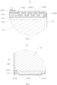
FIG. 5 is an enlarged schematic diagram of a partial structure at region A shown inFIG. 4 . -
FIG. 6 is an enlarged schematic diagram of a partial structure at region B shown inFIG. 4 . -
FIG 7 is a bottom view of the battery provided by an embodiment of the present disclosure. -
FIG. 8 is a cross-sectional view taken along a line C-C shown inFIG. 7 . -
FIG. 9 is an enlarged schematic diagram of a partial structure at region D shown inFIG. 8 . -
FIG. 10 is a bottom view of another battery according to an embodiment of the present disclosure. -
FIG. 11 is a cross-sectional view taken along a line E-E shown inFIG. 10 . -
FIG. 12 is an enlarged schematic diagram of a partial structural at region F shown inFIG. 11 . -
FIG. 13 is a schematic structural diagram of a vehicle according to an embodiment of the present disclosure. - Reference numerals: 1, battery; 10, vehicle; 101, battery pack; 102, vehicle body; 1011, battery module; 1012, box; 11, cap assembly; 111, cover plate; 1111, welding portion; 1112, explosion-proof valve; 11121, explosion-proof notch; 1113, limiting portion; 1114, liquid injection hole; 112, busbar plate; 113, terminal; 114, energy absorption structure; 1141, sealing ring; 1142, plastic pad; 11421, first annular groove; 11422, second annular groove; 11423: isolation portion; 12: housing; 13, cell; 131, first electrode tab; 132, second electrode tab; 14, solder portion; 15, bead portion.
- In the description of the present disclosure, unless otherwise clearly specified and limited, the terms "mounted", "connected with", and "fixed" should be interpreted broadly, and may be, for example, fixed connections, detachable connections, or integral connections; it may be mechanical or electrical connections; it may also be direct connections or indirect connections via intervening structures; it may also be inner communications of two elements or interaction relationships between two elements. The specific meanings of the above terms in the present disclosure can be understood by one of ordinary skill in the art according to specific situations.
- In the present disclosure, unless otherwise clearly specified or limited, a first feature is "on" or "under" a second feature may include an embodiment in which the first feature is in direct contact with the second feature, or may also include an embodiment in which the first feature and the second feature are not in direct contact with each other, but are contacted via another feature formed therebetween. Furthermore, a first feature is "on", "above", or "on top of" a second feature may include an embodiment in which the first feature is right or obliquely "on", "above", or "on top of" the second feature, or just means that the first feature is at a height higher than that of the second feature. A first feature is "below", "under", or "on bottom of" a second feature may include an embodiment in which the first feature is right or obliquely "below", "under", or "on bottom of" the second feature, or just means that the first feature is at a height lower than that of the second feature.
- It should be understood that orientations or positional relationships indicated by the terms "center", "longitudinal", "transverse", "length", "width", "thickness", "upper", "lower", "front", "rear", "left", "right", "vertical", "horizontal", "top", "bottom", "inner", "outer", "clockwise", "counterclockwise", "axial", "radial", "circumferential", and the like are based on the orientations or positional relationships shown in the accompanying drawings. It is merely for the convenience of describing the present disclosure and simplifying the description, rather than indicating or implying that the indicated device or element must have a specific orientation, be constructed and operated in a specific orientation, and therefore should not be understood as a limitation on the present disclosure. In the description of the present disclosure, unless otherwise specified, "a plurality of" means two or more. Furthermore, the terms "first" and "second" are only used for distinguishing in description, and do not have a special meaning. The terms "first position" and "second position" mean two different positions.
- The present disclosure is further described below with reference to the accompanying drawings and embodiments.
- The present embodiment provides a vehicle, which includes a vehicle body and a battery pack. The battery pack is provided in the vehicle body, and supplies electric power to the vehicle body to drive the vehicle body to move. The battery pack includes a box and a battery module. The battery module is provided in the box, that is, the battery module is fixed and protected by the box. In an embodiment, in order to increase the maximum amount of electricity that can be stored in the entire battery module as far as possible, as shown in
FIG. 1 , the battery module includes a plurality ofbatteries 1, and the plurality ofbatteries 1 are arranged in multiple rows and multiple columns. The number and the specific arrangement manner of thebatteries 1 may be adjusted according to actual situations, which is not limited in this embodiment. - As shown in
FIGS. 2 ,3 and4 , the battery includes acell 13, ahousing 12 and acap assembly 11. Thehousing 12 is configured to accommodate thecell 13. Thecap assembly 11 is respectively connected to thecell 13 and thehousing 12. Thecap assembly 11 includes acover plate 111, abusbar plate 112 and a terminal 113. Thecover plate 111 is arranged at a bottom end of thehousing 12 and is connected to asecond electrode tab 132 of thecell 13. Thebusbar plate 112 is attached to a top end of thecell 13, so as to be connected to afirst electrode tab 131 of thecell 13. The terminal 113 penetrates a top end of thehousing 12 and is electrically coupled to thebusbar plate 112, and a gap exists between a top end of thebusbar plate 112 and a bottom end of the terminal 113. In this embodiment, thefirst electrode tab 131 is a positive electrode tab, and thesecond electrode tab 132 is a negative electrode tab. - In the
cap assembly 11 in this embodiment, friction and collision can be avoided during assembly and use by leaving a gap between thebusbar plate 112 and the terminal 113, thereby ensuring the working performance and service life of thebattery 1 as far as possible, and minimizing the number of components required for thecap assembly 11 as far as possible, saving manufacturing costs and reducing assembly and disassembly processes. Thecap assembly 11 can avoid friction and collision during assembly and use, thereby ensuring the working performance and service life of thebattery 1 as much as possible, and minimizing the number of components required for thecap assembly 11 as much as possible, saving manufacturing costs and reducing assembly and disassembly processes. - In this embodiment, as shown in
FIGS. 3 ,4 and5 , thecap assembly 11 further includes anenergy absorption structure 114. Theenergy absorption structure 114 is connected to the terminal 113, thehousing 12 and thebusbar plate 112 respectively, and theenergy absorption structure 114 is configured to create a gap between the top end of thebusbar plate 112 and the bottom end of the terminal 113. By providing theenergy absorption structure 114, it can provide shock absorption and buffering effects among the terminal 113, thehousing 12 and thebusbar plate 112, thereby enhancing the ability of shock resistance and impact resistance of thebattery 1, and prolonging the service life of theentire battery 1. - In an embodiment, the
energy absorption structure 114 includes asealing ring 1141 and aplastic pad 1142. Thesealing ring 1141 is arranged between thehousing 12 and the terminal 113. Theplastic pad 1142 is arranged between thehousing 12 and thebusbar plate 112. Thesealing ring 1141 penetrates through theplastic pad 1142. By providing thesealing ring 1141, sealing between the terminal 113 and thehousing 12 can be achieved, thereby ensuring the use safety of thecap assembly 11. Furthermore, a gap is formed between the top end of thebusbar plate 112 and the bottom end of the terminal 113 by cooperation of thesealing ring 1141 and theplastic pad 1142. In an embodiment, the material of thesealing ring 1141 may be rubber resistant to electrolyte or elastic plastic resistant to electrolyte. - In this embodiment, surfaces of the
plastic pad 1142 is provided concavely and convexly to absorb stress generated when theplastic pad 1142 swells, reduce a pressure applied by the stress to thecell 13 and thehousing 12, and absorb a pressure generated when thecell 13 expands due to charging. - In an embodiment, a top surface of the
plastic pad 1142 is provided with a plurality of firstannular grooves 11421. The plurality of firstannular grooves 11421 are equidistantly distributed along a radial direction, so as to improve the shock absorption and buffering effects of the entireenergy absorption structure 114. A bottom surface of theplastic pad 1142 is provided with a plurality of secondannular grooves 11422. The plurality of secondannular grooves 11422 are equidistantly distributed along the radial direction. Becauseplastic pad 1142 will swell in the electrolyte of thebattery 1, the stress generated by theplastic pad 1142 during swelling can be absorbed by the firstannular groove 11421 and the secondannular groove 11422, so as to reduce the pressure of the stress applied to thecell 13 and thehousing 12. When thecell 13 is subjected to expansion due to charging, the pressure caused by the expansion of thecell 13 can also be absorbed by the firstannular groove 11421 and the secondannular groove 11422. - In an embodiment, the first
annular grooves 11421 and the secondannular grooves 11422 are distributed in a staggered manner, so that the surfaces of theplastic pad 1142 is uneven, thereby further enhancing the shock absorption and buffering effects of theentire plastic pad 1142. - In the embodiment, an edge of the
plastic pad 1142 extends in a direction close to thebusbar plate 112 to form anisolation portion 11423, and theplastic pad 1142 can cover thebusbar plate 112 through theisolation portion 11423. One side of theisolation portion 11423 away from thebusbar plate 112 is fit with an inner wall of thehousing 12, that is, a side peripheral wall of thebusbar plate 112 is separated from the inner wall of thehousing 12 through theisolation portion 11423, so as to avoid direct contact between thebusbar plate 112 and thehousing 12, thereby improving the pressure resistance of theentire battery 1. In an embodiment, thebusbar plate 112 is made of aluminum. - In an embodiment, in order to avoid stress concentration when the
isolation portion 11423 abuts against thehousing 12, an end surface of theisolation portion 11423 away from thecell 13 is provided with a chamfer, that is, the stress is dispersed through the chamfer, so as to prolong the service life of theplastic pad 11423. - In an embodiment, an angle of the chamfer is less than or equal to 60°.
- In an embodiment, in order to enable the
plastic pad 1142 to cover thebusbar plate 112 through theisolation portion 11423, theisolation portion 11423 and theplastic pad 1142 form a receiving groove for receiving thebusbar plate 112. A side wall of the receiving groove is fit with at least a part of a side wall of thebusbar plate 112, and at least a part of a bottom of the receiving groove is in contact with a top surface of thebusbar plate 112. - In an embodiment, in order to improve the protection to the
busbar plate 112, a depth of the receiving groove is adapted to a thickness of thebusbar plate 112, and a diameter of the receiving groove is adapted to a diameter of thebusbar plate 112, so that all surfaces of thebusbar plate 112 except those in contact with thecell 13 can be attached to the receiving groove, thereby preventing thebusbar plate 112 from moving in the receiving groove and causing unnecessary abrasion. - As shown in
FIG. 6 to FIG. 12 , thecover plate 111 is provided withwelding portions 1111 and explosion-proof valves 1112. Thewelding portion 1111 protrudes relative to thecover plate 111 in a direction close to thecell 13, and the explosion-proof valve 1112 protrudes relative to thecover plate 111 in a direction away from thecell 13. That is, thewelding portion 1111 is welded to asecond electrode tab 132 of thecell 13, and the explosion-proof valve 1112 performs an explosion-proof function on thecell 13. In addition, because thewelding portion 1111 protrudes relative to thecover plate 111 in a direction close to thecell 13, the explosion-proof valve 1112 protrudes relative to thecover plate 111 in a direction away from thecell 13, that is, a top surface of thecover plate 111 is spaced from a bottom surface of thesecond electrode tab 132 by a distance h1, and a bottom surface of the explosion-proof valve 1112 is spaced from the bottom surface of thesecond electrode tab 132 by a distance h2, thus, it can be seen that h2>h1>0, and thus the force generated when thecell 13 expands can be absorbed by h1, and a height difference between h2 and h1 can be used to collect explosion gas, while ensuring the stable connection between thecover plate 111 and thesecond electrode tab 132, avoiding the spontaneous combustion and explosion of thebattery 1 due to excessive internal pressure, thereby improving the safety of thebattery 1. - In an embodiment, the width of the explosion-
proof valve 1112 is less than half of the radius of thehousing 12, so as to reduce the exhaust space required for the entire battery module as far as possible. - In an embodiment, the explosion-
proof valve 1112 is provided with an explosion-proof notch 11121. The explosion-proof notch 11121 is formed by stamping, so that when an internal pressure of thebattery 1 is excessively high, the gas in thehousing 12 can be released along the explosion-proof notch 11121, thereby reducing the damage to the periphery of thebattery 1 caused by the gas release. - In an embodiment, a plurality of
welding portions 1111 are provided, and the plurality ofwelding portions 1111 are annularly arranged on thecover plate 111, so as to ensure the stability of the connection with thesecond electrode tab 132. In an embodiment, threewelding portions 1111 are provided. - In an embodiment, as shown in
FIG. 7 orFIG. 10 , thewelding portion 1111 is in an arc-shaped, and an optimal arc length of thewelding portion 1111 is greater than half of a radius of thecell 13, so as to ensure a maximum contact area between thecell 13 and thecover plate 111 as far as possible, thereby improving stability of electrical connection between thecell 13 and thecover plate 111. In other embodiments, thewelding portion 1111 may also be in other shapes, as long as thewelding portion 1111 and thesecond electrode tab 132 can be stably welded, which is not limited in this embodiment. - In an embodiment, a plurality of explosion-
proof valves 1112 are provided, and the plurality of explosion-proof valves 1112 are respectively annularly arranged on thecover plate 111, so as to improve the explosion-proof performance. In an embodiment, three explosion-proof valve 1112 are provided. - In an embodiment, the
welding portions 1111 and the explosion-proof valves 1112 are distributed in a staggered manner, so as to ensure that the force applied to theentire cover plate 111 is balanced, thereby improving gas flowability inside thehousing 12. - In other embodiments, as shown in
FIG. 10 , thecover plate 111 is further provided with aliquid injection hole 1114 for liquid injection or gap exhaust. - In an embodiment, the
liquid injection hole 1114 coincides with an axis of thecell 13, that is, theliquid injection hole 1114 is arranged at a center of thecover plate 111, so as to ensure the force on theentire cover plate 111 is balanced. - In an embodiment, the
cover plate 111 protrudes along an edge of theliquid injection hole 1114 in a direction close to thecell 13 to form a liquid injection boss, thereby further increasing structural strength of the middle portion of thecover plate 111. - In this embodiment, as shown in
FIGS. 7 to 9 , the peripheral edge of thecover plate 111 is provided with a limitingportion 1113. The limitingportion 1113 protrudes with respect to thecover plate 111 in a direction close to thecell 13 to surround thesecond electrode tab 132. That is, thesecond electrode tab 132 is positioned through the limitingportion 1113, so that the strength of theentire cover plate 111 can be enhanced, and it can also facilitate accurate welding between thesecond electrode tab 132 and thewelding portion 1111 in the future, so as to avoid thesecond electrode tab 132 being displaced by force during welding, which may cause thesecond electrode tab 132 to be close to the inner wall of thehousing 12, resulting in a poor welding and a poor performance of the use of thecell 13. In addition, because the limitingportion 1113 can surround thesecond electrode tab 132, damage of thesecond electrode tab 132 may also be avoided when assembling thecell 13. - In an embodiment, a surface of the limiting
portion 1113 in contact with thesecond electrode tab 132 is inclined, that is, a cross section of the limitingportion 113 gradually decreases in a direction from thesecond electrode tab 132 to thefirst electrode tab 131, so as to further improve a restraint capability of thesecond electrode tab 132, and minimize the occurrence of displacement of thesecond electrode tab 132 as far as possible. - Considering that after the
cell 13 is placed into thehousing 12 through an opening at the bottom end of thehousing 12, it is necessary to cover and fix thecover plate 111 at the opening. That is, the outer circumferential edge of thecover plate 111 and the bottom end of thehousing 12 are welded together by solder, so that asolder portion 14 is formed at the connection between thehousing 12 and thecover plate 111, thereby achieving a stable connection between thecover plate 111 and thehousing 12. - As shown in
FIGS. 10 to 12 , in other embodiments, a first chamfer may be provided on thehousing 12 along the edge of the opening, and a corresponding second chamfer is provided on thecover plate 111. When thecover plate 111 and thehousing 12 are welded by means of welding, awelding bead 15 can be formed at the connection between thehousing 12 and thecover plate 111, which not only facilitates welding and reduces stress concentration, but also further improves stability of the connection between thecover plate 111 and thehousing 12. - As shown in
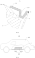
FIG. 13 , the present embodiment provides avehicle 10, which includes avehicle body 102 and abattery pack 101. Thebattery pack 101 is arranged in thevehicle body 102, and supplies electric power to thevehicle body 102 to drive the vehicle body to move. Thebattery pack 101 includes abox 1012 and abattery module 1011. Thebattery module 1011 is arranged in thebox 1012, and thebattery module 1011 is fixed and protected by means of thebox 1012. - In the description of this specification, the description with reference to the terms "some embodiments", "other embodiments", etc., means that the specific features, structures, materials or characteristics described in connection with the embodiment or example are included in at least one embodiment or example of the present disclosure. In this specification, the exemplary expressions of the above terms do not necessarily refer to the same embodiment or example. Furthermore, the specific features, structures, materials, or characteristics may be combined in any suitable manner in any one or more embodiments or examples.
Claims (10)
- A cap assembly applied to a battery that comprising a cell (13) and a housing (12) for accommodating the cell (13); the cap assembly comprising:a busbar plate (112) arranged in the housing (12) and attached to a top end of the cell (13), so as to be connected to the cell (13); anda plastic pad (1142) arranged between the housing (12) and the busbar plate (112); wherein an edge of the plastic pad (1142) extends in a direction close to the busbar plate (112) to form an isolation portion (11423); the plastic pad (1142) is able to cover the busbar plate (112) through the isolation portion (11423); and the isolation portion (11423) is able to be fit with an inner wall of the housing (12).
- The cap assembly according to claim 1, wherein an end face of the isolation portion (11423) away from the cell (13) is provided with a chamfer.
- The cap assembly according to claim 2, wherein an angle of the chamfer is less than or equal to 60°.
- The cap assembly according to any one of claims 1 to 3, wherein the isolation portion (11423) and the plastic pad (1142) form a receiving groove for receiving the busbar plate (112); a side wall of the receiving groove is attached to at least a part of a side wall of the busbar plate (112), and at least a part of a bottom of the receiving groove is in contact with a top surface of the busbar plate (112).
- The cap assembly according to claim 4, wherein a depth of the receiving groove is adapted to a thickness of the busbar plate (112).
- The cap assembly according to claim 4, wherein a diameter of the receiving groove is adapted to a diameter of the busbar plate (112).
- A battery comprising a cell (13), a housing (12), and the cap assembly according to any one of claims 1 to 6, wherein the housing (12) is configured to accommodate the cell (13); the cap assembly is respectively connected to the cell (13) and the housing (12).
- A battery module comprising a plurality of batteries according to claim 7, wherein the plurality of batteries are arranged in multiple rows and multiple columns.
- A battery pack comprising a box and the battery module according to claim 8, wherein the battery module is provided in the box.
- A vehicle comprising a vehicle body and the battery pack according to claim 9, wherein the battery pack is provided in the vehicle body.
Applications Claiming Priority (2)
| Application Number | Priority Date | Filing Date | Title |
|---|---|---|---|
| CN202221650525.6U CN217788588U (en) | 2022-06-28 | 2022-06-28 | A cap assembly, battery, battery module, battery pack and vehicle |
| PCT/CN2022/127074 WO2024000947A1 (en) | 2022-06-28 | 2022-10-24 | Cap assembly, battery, battery module, battery pack, and vehicle |
Publications (2)
| Publication Number | Publication Date |
|---|---|
| EP4475296A1 true EP4475296A1 (en) | 2024-12-11 |
| EP4475296A4 EP4475296A4 (en) | 2025-07-02 |
Family
ID=83937387
Family Applications (1)
| Application Number | Title | Priority Date | Filing Date |
|---|---|---|---|
| EP22949032.1A Pending EP4475296A4 (en) | 2022-06-28 | 2022-10-24 | CAP ASSEMBLY, BATTERY, BATTERY MODULE, BATTERY PACK AND VEHICLE |
Country Status (5)
| Country | Link |
|---|---|
| US (1) | US20250023213A1 (en) |
| EP (1) | EP4475296A4 (en) |
| CN (1) | CN217788588U (en) |
| DE (1) | DE212022000379U1 (en) |
| WO (1) | WO2024000947A1 (en) |
Families Citing this family (1)
| Publication number | Priority date | Publication date | Assignee | Title |
|---|---|---|---|---|
| CN120728114A (en) * | 2024-03-27 | 2025-09-30 | 比亚迪股份有限公司 | Battery cell cover assembly, battery cell, battery assembly and electrical device |
Family Cites Families (6)
| Publication number | Priority date | Publication date | Assignee | Title |
|---|---|---|---|---|
| JP3717684B2 (en) * | 1998-10-30 | 2005-11-16 | 三洋電機株式会社 | Cylindrical secondary battery |
| JP4702640B2 (en) * | 2008-04-18 | 2011-06-15 | トヨタ自動車株式会社 | battery |
| CN208862041U (en) * | 2018-10-12 | 2019-05-14 | 深圳新恒业电池科技有限公司 | Nut cap and battery |
| CN212342702U (en) * | 2020-05-12 | 2021-01-12 | 路华置富电子(深圳)有限公司 | Battery cap and battery using same |
| CN113097612A (en) * | 2021-04-19 | 2021-07-09 | 惠州惠峰科技有限公司 | Cylindrical battery |
| CN113346201A (en) * | 2021-05-21 | 2021-09-03 | 湖北亿纬动力有限公司 | Cylindrical battery, battery module and battery pack |
-
2022
- 2022-06-28 CN CN202221650525.6U patent/CN217788588U/en active Active
- 2022-10-24 EP EP22949032.1A patent/EP4475296A4/en active Pending
- 2022-10-24 DE DE212022000379.9U patent/DE212022000379U1/en active Active
- 2022-10-24 WO PCT/CN2022/127074 patent/WO2024000947A1/en not_active Ceased
-
2024
- 2024-09-30 US US18/900,949 patent/US20250023213A1/en active Pending
Also Published As
| Publication number | Publication date |
|---|---|
| CN217788588U (en) | 2022-11-11 |
| US20250023213A1 (en) | 2025-01-16 |
| EP4475296A4 (en) | 2025-07-02 |
| DE212022000379U1 (en) | 2024-11-11 |
| WO2024000947A1 (en) | 2024-01-04 |
Similar Documents
| Publication | Publication Date | Title |
|---|---|---|
| CN217788587U (en) | Cap assembly, battery module, battery pack and vehicle | |
| US10629879B2 (en) | Battery module | |
| CN217788572U (en) | Cap assembly, battery module, battery pack and vehicle | |
| US11721861B2 (en) | Top cover assembly for battery, battery, and energy storage device | |
| US11984608B2 (en) | Battery cell, battery, power consumption apparatus, method and apparatus for producing battery cell | |
| US20250158177A1 (en) | Top cover assembly, energy storage device, and energy storage system | |
| CN220628150U (en) | A cylindrical cell, battery pack and electronic equipment | |
| US20250023213A1 (en) | Cap assembly, battery, battery module, battery pack and vehicle | |
| CN115020884A (en) | Cap assembly, battery module, battery pack and vehicle | |
| US20230122619A1 (en) | Battery cell, battery, power consumption device, and manufaturing method and device of battery cell | |
| CN107112137A (en) | The external terminal of the apparatus for storing electrical energy of liquid-leakage preventing structure with electrolyte | |
| CN218039492U (en) | Cap assembly, battery module, battery pack and vehicle | |
| US20240356172A1 (en) | Battery cell, battery and power consuming device | |
| CN220382285U (en) | Poles, top cover components, battery cells, batteries and electrical devices | |
| CN219717171U (en) | Cylindrical battery | |
| CN218039696U (en) | A cap assembly, battery, battery module, battery pack and vehicle | |
| WO2024000948A1 (en) | Cap assembly, battery, battery module, battery pack, and vehicle | |
| CN221530022U (en) | Secondary batteries and battery packs | |
| CN222735155U (en) | Cylindrical battery and electronic device | |
| CN221041301U (en) | Cylindrical battery, battery pack and electronic equipment | |
| CN220692160U (en) | Current collecting cover plate of battery and battery | |
| CN221552023U (en) | End cover assembly, battery cell and energy storage device | |
| CN223797464U (en) | Battery device and electricity utilization device | |
| CN223218422U (en) | Full-tab battery and electric equipment | |
| CN222126587U (en) | Batteries and battery packs |
Legal Events
| Date | Code | Title | Description |
|---|---|---|---|
| STAA | Information on the status of an ep patent application or granted ep patent |
Free format text: STATUS: THE INTERNATIONAL PUBLICATION HAS BEEN MADE |
|
| PUAI | Public reference made under article 153(3) epc to a published international application that has entered the european phase |
Free format text: ORIGINAL CODE: 0009012 |
|
| STAA | Information on the status of an ep patent application or granted ep patent |
Free format text: STATUS: REQUEST FOR EXAMINATION WAS MADE |
|
| 17P | Request for examination filed |
Effective date: 20240902 |
|
| AK | Designated contracting states |
Kind code of ref document: A1 Designated state(s): AL AT BE BG CH CY CZ DE DK EE ES FI FR GB GR HR HU IE IS IT LI LT LU LV MC ME MK MT NL NO PL PT RO RS SE SI SK SM TR |
|
| A4 | Supplementary search report drawn up and despatched |
Effective date: 20250530 |
|
| RIC1 | Information provided on ipc code assigned before grant |
Ipc: H01M 50/593 20210101ALI20250523BHEP Ipc: H01M 50/152 20210101ALI20250523BHEP Ipc: H01M 50/528 20210101ALI20250523BHEP Ipc: H01M 50/59 20210101ALI20250523BHEP Ipc: H01M 50/16 20210101AFI20250523BHEP |
|
| DAX | Request for extension of the european patent (deleted) | ||
| RAV | Requested validation state of the european patent: fee paid |
Extension state: MA Effective date: 20240902 |