EP4475279A1 - Ccs assembly and battery pack - Google Patents
Ccs assembly and battery pack Download PDFInfo
- Publication number
- EP4475279A1 EP4475279A1 EP23783289.4A EP23783289A EP4475279A1 EP 4475279 A1 EP4475279 A1 EP 4475279A1 EP 23783289 A EP23783289 A EP 23783289A EP 4475279 A1 EP4475279 A1 EP 4475279A1
- Authority
- EP
- European Patent Office
- Prior art keywords
- grooves
- wiring harness
- collection
- wiring
- assembly according
- Prior art date
- Legal status (The legal status is an assumption and is not a legal conclusion. Google has not performed a legal analysis and makes no representation as to the accuracy of the status listed.)
- Pending
Links
Images






Classifications
-
- H—ELECTRICITY
- H01—ELECTRIC ELEMENTS
- H01M—PROCESSES OR MEANS, e.g. BATTERIES, FOR THE DIRECT CONVERSION OF CHEMICAL ENERGY INTO ELECTRICAL ENERGY
- H01M50/00—Constructional details or processes of manufacture of the non-active parts of electrochemical cells other than fuel cells, e.g. hybrid cells
- H01M50/50—Current conducting connections for cells or batteries
- H01M50/502—Interconnectors for connecting terminals of adjacent batteries; Interconnectors for connecting cells outside a battery casing
- H01M50/503—Interconnectors for connecting terminals of adjacent batteries; Interconnectors for connecting cells outside a battery casing characterised by the shape of the interconnectors
-
- H—ELECTRICITY
- H01—ELECTRIC ELEMENTS
- H01M—PROCESSES OR MEANS, e.g. BATTERIES, FOR THE DIRECT CONVERSION OF CHEMICAL ENERGY INTO ELECTRICAL ENERGY
- H01M50/00—Constructional details or processes of manufacture of the non-active parts of electrochemical cells other than fuel cells, e.g. hybrid cells
- H01M50/50—Current conducting connections for cells or batteries
- H01M50/502—Interconnectors for connecting terminals of adjacent batteries; Interconnectors for connecting cells outside a battery casing
- H01M50/507—Interconnectors for connecting terminals of adjacent batteries; Interconnectors for connecting cells outside a battery casing comprising an arrangement of two or more busbars within a container structure, e.g. busbar modules
-
- H—ELECTRICITY
- H01—ELECTRIC ELEMENTS
- H01M—PROCESSES OR MEANS, e.g. BATTERIES, FOR THE DIRECT CONVERSION OF CHEMICAL ENERGY INTO ELECTRICAL ENERGY
- H01M50/00—Constructional details or processes of manufacture of the non-active parts of electrochemical cells other than fuel cells, e.g. hybrid cells
- H01M50/20—Mountings; Secondary casings or frames; Racks, modules or packs; Suspension devices; Shock absorbers; Transport or carrying devices; Holders
- H01M50/289—Mountings; Secondary casings or frames; Racks, modules or packs; Suspension devices; Shock absorbers; Transport or carrying devices; Holders characterised by spacing elements or positioning means within frames, racks or packs
- H01M50/293—Mountings; Secondary casings or frames; Racks, modules or packs; Suspension devices; Shock absorbers; Transport or carrying devices; Holders characterised by spacing elements or positioning means within frames, racks or packs characterised by the material
-
- H—ELECTRICITY
- H01—ELECTRIC ELEMENTS
- H01M—PROCESSES OR MEANS, e.g. BATTERIES, FOR THE DIRECT CONVERSION OF CHEMICAL ENERGY INTO ELECTRICAL ENERGY
- H01M50/00—Constructional details or processes of manufacture of the non-active parts of electrochemical cells other than fuel cells, e.g. hybrid cells
- H01M50/50—Current conducting connections for cells or batteries
- H01M50/502—Interconnectors for connecting terminals of adjacent batteries; Interconnectors for connecting cells outside a battery casing
- H01M50/514—Methods for interconnecting adjacent batteries or cells
- H01M50/516—Methods for interconnecting adjacent batteries or cells by welding, soldering or brazing
-
- H—ELECTRICITY
- H01—ELECTRIC ELEMENTS
- H01M—PROCESSES OR MEANS, e.g. BATTERIES, FOR THE DIRECT CONVERSION OF CHEMICAL ENERGY INTO ELECTRICAL ENERGY
- H01M50/00—Constructional details or processes of manufacture of the non-active parts of electrochemical cells other than fuel cells, e.g. hybrid cells
- H01M50/50—Current conducting connections for cells or batteries
- H01M50/572—Means for preventing undesired use or discharge
- H01M50/584—Means for preventing undesired use or discharge for preventing incorrect connections inside or outside the batteries
- H01M50/59—Means for preventing undesired use or discharge for preventing incorrect connections inside or outside the batteries characterised by the protection means
-
- H—ELECTRICITY
- H01—ELECTRIC ELEMENTS
- H01M—PROCESSES OR MEANS, e.g. BATTERIES, FOR THE DIRECT CONVERSION OF CHEMICAL ENERGY INTO ELECTRICAL ENERGY
- H01M50/00—Constructional details or processes of manufacture of the non-active parts of electrochemical cells other than fuel cells, e.g. hybrid cells
- H01M50/20—Mountings; Secondary casings or frames; Racks, modules or packs; Suspension devices; Shock absorbers; Transport or carrying devices; Holders
- H01M50/204—Racks, modules or packs for multiple batteries or multiple cells
- H01M50/207—Racks, modules or packs for multiple batteries or multiple cells characterised by their shape
- H01M50/213—Racks, modules or packs for multiple batteries or multiple cells characterised by their shape adapted for cells having curved cross-section, e.g. round or elliptic
-
- H—ELECTRICITY
- H01—ELECTRIC ELEMENTS
- H01M—PROCESSES OR MEANS, e.g. BATTERIES, FOR THE DIRECT CONVERSION OF CHEMICAL ENERGY INTO ELECTRICAL ENERGY
- H01M50/00—Constructional details or processes of manufacture of the non-active parts of electrochemical cells other than fuel cells, e.g. hybrid cells
- H01M50/50—Current conducting connections for cells or batteries
- H01M50/502—Interconnectors for connecting terminals of adjacent batteries; Interconnectors for connecting cells outside a battery casing
- H01M50/521—Interconnectors for connecting terminals of adjacent batteries; Interconnectors for connecting cells outside a battery casing characterised by the material
- H01M50/522—Inorganic material
-
- Y—GENERAL TAGGING OF NEW TECHNOLOGICAL DEVELOPMENTS; GENERAL TAGGING OF CROSS-SECTIONAL TECHNOLOGIES SPANNING OVER SEVERAL SECTIONS OF THE IPC; TECHNICAL SUBJECTS COVERED BY FORMER USPC CROSS-REFERENCE ART COLLECTIONS [XRACs] AND DIGESTS
- Y02—TECHNOLOGIES OR APPLICATIONS FOR MITIGATION OR ADAPTATION AGAINST CLIMATE CHANGE
- Y02E—REDUCTION OF GREENHOUSE GAS [GHG] EMISSIONS, RELATED TO ENERGY GENERATION, TRANSMISSION OR DISTRIBUTION
- Y02E60/00—Enabling technologies; Technologies with a potential or indirect contribution to GHG emissions mitigation
- Y02E60/10—Energy storage using batteries
Definitions
- the present disclosure relates to the field of battery technologies, and in particular, to cell contact system (CCS) assemblies and battery packs.
- CCS cell contact system
- a battery pack in related art mostly use a cell contact system (CCS) assembly for series and parallel connection of single batteries in the battery pack and for collections of the temperature and pressure signals.
- CCS cell contact system
- a conventional CCS assembly includes components such as a busbar, a bracket, and a collection wiring harness.
- the components such as the busbar and the collection wiring harness are mostly integrated on the bracket.
- glue is usually poured over the entire CCS assembly to attach the components such as aluminum bars and the collection wiring harness to the bracket.
- An upper surface of the bracket in the related art is provided with an upper accommodating groove configured to accommodate the busbar.
- the glue is directly poured over the busbar, and the glue flows to a gap between the busbar and the upper accommodating groove to realize bonding and fixing of the two.
- a glue irrigation area of this fixing method is large, the time for the glue to flow to the gap between the busbar and the upper accommodating groove is long, the production costs is high, and the bonding efficiency is low.
- a first object of the present disclosure is to provide a CCS assembly that is easy to bond and requires less glue.
- a CCS assembly including: busbars; a plastic bracket, having an upper surface provided with upper accommodating grooves configured to accommodate the busbars, having a lower surface provided with lower accommodating grooves configured to accommodate single batteries, and the upper accommodating grooves communicating with the lower accommodating grooves to make the busbars abut against the single batteries; glue guiding grooves, disposed on the upper surface of the plastic bracket, and each of the glue guiding grooves communicating with the upper accommodating grooves adjacent thereto.
- the busbars include an input bar, current guide bars, series connection bars, and an output bar, all of which are correspondingly embedded in the upper accommodating grooves; the current guide bars cooperate with the input bar and the output bar to connect every two adjacent ones of the single batteries in series in a first direction, and to connect two adjacent ones of the single batteries in parallel in a second direction; current guide groups each including a plurality of the current guide bars connected in series along the first direction are defined, and each of the series connection bars is configured to connect two adjacent ones of the current guide groups arranged along the second direction in series; and the glue guiding groove each of the glue guiding grooves extends along the first direction.
- the CCS assembly further includes collection wiring harnesses, input ends of the collection wiring harnesses are electrically connected to the busbars or the single batteries; wiring harness grooves each extending along the first direction are provided on the plastic bracket, the collection wiring harnesses are embedded in the wiring harness grooves, and the wiring harness grooves are arranged in one-to-one correspondence with the current guide groups; and the wiring harness grooves are arranged adjacent to the glue guiding grooves, and each of the wiring harness grooves communicates with the glue guiding grooves adjacent thereto.
- a height of a bottom inner surface of each of the glue guiding grooves is not lower than a height of a bottom inner surface of each of the wiring harness grooves.
- each of the wiring harness grooves is provided with a glue discharge hole running through a bottom thereof.
- branch grooves are provided on the upper surface of the plastic bracket, an extending direction of each of the branch grooves is arranged at an included angle with an extending direction of each of the wiring harness grooves; each of the branch grooves is configured to communicate with a corresponding one of the wiring harness grooves and one of the upper accommodating grooves corresponding to the corresponding one of the wiring harness grooves, collection single wirings of the collection wiring harnesses extend to the upper accommodating grooves corresponding to the collection wiring harnesses through the branch grooves; and a height of a bottom inner surface of each of glue guiding grooves is not lower than a height of a bottom inner surface of each of the branch grooves.
- a height of a bottom inner surface of each of the upper accommodating grooves is not higher than the height of the bottom inner surface of each of the branch grooves; and the height of the bottom inner surface of each of the upper accommodating grooves is not higher than the height of the bottom inner surface of each of the glue guiding grooves.
- both sides of each of the current guide groups along the first direction are provided with the glue guiding grooves.
- each of the upper accommodating grooves includes a plurality of first grooves arranged along the first direction, each of the first grooves includes at least two installation areas arranged at intervals in the second direction, and two adjacent ones of the installation areas are communicated with each other through a second groove; and at least one of the glue guiding grooves is arranged between the two adjacent ones of the installation areas and communicates with the second groove.
- an output end of the plastic bracket is provided with leading wire notches corresponding to the wiring harness grooves one by one, each of the leading wire notches communicates with a corresponding one of the wiring harness grooves, and the collection wiring harnesses protrude from the wiring harness grooves by passing through the leading wire notches;
- the CCS assembly further includes sealing buckles disposed on the plastic bracket and configured to seal the leading wire notches; and the collection wiring harnesses protrude from the wiring harness grooves by passing through the sealing buckles.
- each of the sealing buckles includes a base plate, a limiting plate, and a connecting block, and the base plate is connected with the limiting plate through the connecting block; the connecting block is clamped in one of the leading wire notches, the limiting plate is located inside the output end of the plastic bracket, and the base plate is located outside the output end of the plastic bracket; and the base plate is provided with a wire hole, and one of the collection wiring harnesses protrudes from one of the wiring harness grooves through the wire hole.
- the plastic bracket includes a main body and a wire hardness tray disposed on the output end of the plastic bracket, the wiring harness grooves, the upper accommodating grooves, and the lower accommodating grooves are all disposed on the main body;
- the wire hardness tray includes a horizontal plate and a longitudinal plate connected with each other, the longitudinal plate is connected to an output end of the main body, and the horizontal plate is disposed on a side of the longitudinal plate away from the main body; the leading wire notches are opened on the longitudinal plate, and the longitudinal plate is located between the base plate and the limiting plate; and the base plate is provided with a wire hole through which one of the collection wiring harnesses protrudes out of one of the wiring harness grooves and extends into an area corresponding to the horizontal plate.
- the CCS assembly further includes cable ties configured to bind the collection wiring harnesses in the area corresponding to the horizontal plate; a lower surface of the horizontal plate is provided with a plurality limiting protrusions every two of which arranged in groups, an area between the every two of the limiting protrusions defines a limiting groove configured to limit one of the cable ties, and the one of the cable ties is located in the limiting groove; and the horizontal plate is provided with first binding holes each running through the horizontal plate and each configured to thread one of the cable ties.
- the CCS assembly further includes cable ties and fixing buckles, which are all configured to fix the collection wiring harness in the area corresponding to horizontal plate; each of the fixing buckles includes two binding buckles correspondingly arranged, one of which is arranged on the horizontal plate, and the other one is arranged on the horizontal plate or the longitudinal plate; the two binding buckles have one of the collection wiring harnesses located therebetween; and each of the binding buckles includes a base, and a second binding hole runs through the base and configured to thread one of the cable ties.
- the horizontal plate is provided with forming ports each running through the horizontal plate and each corresponding to one of the binding buckles.
- wiring pressing strips are provided at each of the wiring harness grooves; the collection wiring harnesses are located between bottoms of the wiring harness grooves and the wiring pressing strips; and the collection wiring harnesses include a plurality of collection single wirings, each of the wiring pressing strips is provided with a through groove configured for the collection single wirings to enter the wiring harness grooves.
- a width of the through groove is greater than or equal to an outer diameter of each of the collection single wirings.
- a length direction of the through groove and an extending direction of each of the wiring harness grooves are arranged at an included angle.
- the included angle between the length direction of the through groove and the extending direction of each of the wiring harness grooves ranges from 10° to 80°.
- a plurality of rib plates are provided between the longitudinal plate and a bottom surface of the main body.
- a battery pack including the above-mentioned CCS assembly.
- orientations or positional relationships indicated by the terms “upper”, “lower”, “front”, “rear”, “left”, “right”, “vertical”, “horizontal”, “top”, “bottom”, “inner”, “outer”, etc. are based on the orientations or positional relationships illustrated in the attached drawings, and are only for the convenience of describing the present disclosure and simplifying the description, rather than indicating or implying that the referred devices or elements have certain orientations, or are constructed or operated in certain orientations, and thus should not be construed as limitations on the present disclosure.
- first and second are only configured for the purpose of description, and cannot be understood as indicating or implying relative importance.
- plurality means two or more.
- and/or includes any and all combinations of one or more of the associated listed items.
- references to "the” object or “an/a” object are likewise intended to represent one of several such objects that may be possible.
- a CCS assembly 200 should be configured as cylindrical power battery modules, including busbars, a plastic bracket 204, and glue guiding grooves 2042.
- an upper surface of the plastic bracket 204 is provided with upper accommodating grooves configuration to accommodate the busbars
- a lower surface of the plastic bracket 204 is provided with lower accommodating grooves 214 configured to accommodate the single batteries 100 of the cylindrical power battery modules
- the upper accommodating groove and the lower accommodating groove 214 communicate with each other to make the busbars abut against the single batteries 100.
- the glue guiding grooves 2042 are arranged on the upper surface of the plastic bracket 204, and each of the glue guiding grooves 2042 communicates with the upper accommodating groove adjacent thereto. In an embodiment, as illustrated in FIG.
- the plastic bracket 204 here includes a main body 204a and a wiring harness tray 204b disposed at an output end of the main body 204a.
- the upper accommodating grooves and the lower accommodating grooves 214 are all arranged on the main body 204a.
- the main body 204a here has a plate shape.
- a shape of the upper accommodating groove is adapted to a shape of the busbar.
- the busbars are first assembled into the upper accommodating grooves, and the plastic bracket 204 is attached to the single batteries 100, that is to say, the single batteries 100 are assembled into the lower accommodating grooves 214, and then glue is poured into the glue guiding grooves 2042, and the glue in the glue guiding grooves 2042 flows along the glue guiding grooves 2042 to the upper accommodation grooves at this time, that is, the glue in the glue guiding grooves 2042 flows along the glue guiding grooves 2042 to a gap between the busbars and the upper accommodation grooves, so as to realize the bonding and fixing of the busbar and the plastic bracket 204.
- a bonding strength between the busbar and the plastic bracket 204 depends on a bonding area between the busbar and the upper accommodating groove
- a bonding strength between the plastic bracket 204 and the single battery 100 depends on a bonding area between the plastic bracket 204 and the single battery 100.
- this embodiment adopts the glue guiding grooves 2042 to drain the glue, which may accurately drain the glue into the gap between the busbars and the upper accommodating grooves, as well as the gap between the single batteries 100 and the lower accommodating grooves 214, thereby preventing the glue from being coated on the upper surface of the busbars and other irrelevant areas of the plastic bracket 204, improving the bonding efficiency, reducing the amount of the glue on the premise of ensuring the bonding strength, and saving production costs.
- the above-mentioned glue is a heat-conducting gel, which realizes the fixing between the components of the CCS assembly 200 and the fixing between the CCS assembly 200 and the single battery 100, and at the same time improves a heat dissipation efficiency of the battery.
- the busbars include an input bar 201, current guide bars 202, series connection bars 203, and an output bar 206. All of the input bar 201, the current guide bars 202, the series connection bars 203, and the output bar 206 are correspondingly embedded in the upper accommodating grooves.
- the current guide bars 202 cooperate with the input bar 201 and the output bar 206 to connect every two adjacent single batteries 100 arranged in a first direction in series; and the current guide bars 202 cooperate with the input bar 201 and the output bar 206 to connect every two adjacent single batteries 100 arranged in a second direction in parallel.
- the current guide bars 202 are configured to cooperate with the input bar 201 and the output bar 206 to connect every two adjacent single batteries 100 arranged along the first direction in series and connect every two adjacent single batteries 100 arranged along the second direction in parallel.
- a plurality of current guide bars 202 connected in series along the first direction are defined as a current guide group, and each of the series connection bars 203 is configured to connect two adjacent current guide groups arranged along the second direction in series.
- the glue guiding groove 2042 extends along the first direction.
- the first direction is the left-right direction
- the second direction is the front-rear direction.
- the cylindrical power battery in this embodiment is composed of six cylindrical power battery modules arranged in series in the front-rear direction, that is, in the second direction.
- Each single cylindrical power battery module includes a plurality of single batteries 100 connected in series in the left-right direction, that is, in the first direction, multiple single batteries 100 connected in series in the left-right direction is defined as a battery row, and each cylindrical power battery module includes two battery rows connected in parallel in the front-rear direction.
- the current guide bar 202 here is configured to connect two adjacent single batteries 100 arranged in the left-right direction in series, and connect two adjacent single batteries 100 arranged in a same cylindrical power battery module and in the front-rear direction in parallel.
- the series connection bar 203 is configured to connect two adjacent cylindrical power battery modules in series.
- a structure of the glue guiding groove 2042 extending along the first direction enables the same glue guiding groove 2042 to connect multiple upper accommodation grooves in series in the first direction, that is, in the left-right direction, which is beneficial to improve the efficiency of glue filling and bonding.
- the CCS assembly 200 further includes collection wiring harnesses 205.
- An input end of the collection wiring harness 205 is electrically connected to the busbar or the single batteries 100.
- Wiring harness grooves 2041 each extending along the first direction are provided on the plastic bracket 204.
- the collection wiring harness 205 is embedded in the wiring harness groove 2041, and the wiring harness grooves 2041 are arranged in one-to-one correspondence with the current guide groups.
- the wiring harness grooves 2041 are arranged adjacent to the glue guiding grooves 2042, and the wiring harness groove 2041 communicates with the glue guiding groove 2042 adjacent thereto.
- the input end of the collection wiring harness 205 is connected to at least one of the input bar 201, the output bar 206, the current guide bar 202, the series connection bar 203, and the single battery 100.
- a number of the collection wiring harnesses 205 is six, which are set in one-to-one correspondence with the six cylindrical power battery modules.
- the collection single wirings 2051 that make up the collection wiring harness 205 are welded to the busbar of the cylindrical power battery module corresponding to the collection wiring harness 205, so as to realize a comprehensive monitoring of temperature and pressure signals of the cylindrical power battery module.
- the wiring harness groove 2041 here facilitates the wiring of the collection single wirings 2051 that forming the collection wiring harness 205, which may avoid winding and knotting of each collection single wiring 2051 during a welding process of the collection single wiring 2051 and the busbar, which is conducive to improving work efficiency.
- an auxiliary fixing of the collection wiring harnesses 205 may be realized before coating the glue, and the glue in the glue guiding grooves 2042 may flow into the wiring harness grooves 2041 to realize the fixing of the collection wiring harnesses 205 during a glue coating stage, which may effectively improve a fastness of the fixing of the collection wiring harnesses 205.
- a structural design of the wiring harness grooves 2041 may reduce a thickness of the CCS assembly 200, which is conducive to reducing a volume of the cylindrical power battery and improving an energy density of the cylindrical power battery.
- a height of a bottom inner surface of the glue guiding groove 2042 is not lower than a height of a bottom inner surface of the wiring harness groove 2041, so that it is convenient for the glue in the glue guiding groove 2042 to flow into the wiring harness groove 2041.
- the wiring harness grooves 2041 here may also play a role of storing excess glue and fixing serpentine liquid cooling plates 500.
- the battery pack provided in the embodiments includes the CCS assembly 200 and the battery modules in the embodiments.
- the battery pack here is specifically a cylindrical power battery pack, which is composed of six cylindrical power battery modules.
- the battery pack also includes the above-mentioned serpentine liquid cooling plates 500, a number of the serpentine liquid cooling plates 500 is six, and the serpentine liquid cooling plates 500 are arranged in one-to-one correspondence with the six wiring harness grooves 2041.
- the wiring harness groove 2041 is provided with a glue discharge hole 207 running through a bottom thereof. After the glue enters the wiring harness groove 2041, part of the glue flows from the glue discharge hole 207 to an underside of the plastic bracket 204, and to a gap between a bottom outer surface of the wiring harness groove 2041 and the serpentine liquid cooling plate 500, so that the serpentine liquid cooling plate 500 and the single battery 100, and the serpentine liquid cooling plate 500 and the plastic bracket 204 are bonded and fixed.
- the upper surface of the plastic bracket 204 is provided with branch grooves 2044.
- An extending direction of the branch groove 2044 is arranged at an included angle with an extending direction of the wiring harness groove 2041.
- the branch groove 2044 is configured to communicate with the wiring harness groove 2041 and the upper accommodating groove corresponding to the wiring harness groove 2041, and the collection single wirings 2051 of the collection wiring harness 205 extend to the upper accommodating groove corresponding to the collection single wiring 2051 through the branch groove 2044.
- the height of the bottom inner surface of the glue guiding groove 2042 is not lower than a height of a bottom inner surface of the branch groove 2044.
- an included angle between the extending direction of the branch groove 2044 and the extending direction of the wiring harness groove 2041 is 90°, and the glue in the glue guiding grooves 2042 enters the upper accommodating grooves through the branch grooves 2044 to play the role of drainage; in a second aspect, the collection single wiring 2051 stored in the branch groove 2044 is bonded and fixed with the branch groove 2044 by the glue flowing through the branch groove 2044, which has strong firmness and may reduce the possibility of the collection single wiring 2051 shaking during the operation of the battery pack, thereby ensuring the solidity of welding points between the collection single wiring 2051 and the busbar, and high safety.
- the bottom inner surface of the glue guiding groove 2042 is higher than the bottom inner surface of the branch groove 2044.
- a height of a bottom inner surface of the upper accommodating groove is not higher than the height of the bottom inner surface of the branch groove 2044, and the height of the bottom inner surface of the upper accommodating groove is not higher than the height of the bottom inner surface of the glue guiding groove 2042, which is convenient for the glue in the glue guiding grooves 2042 to flow to the upper accommodating grooves, which is beneficial to improve the glue pouring efficiency.
- both sides of the current guide group along the first direction are provided with the glue guiding grooves 2042.
- each of the upper accommodating grooves includes a plurality of first grooves arranged along the first direction.
- Each of the first grooves includes at least two installation areas 2047 arranged at intervals in the second direction, and the two adjacent installation areas 2047 are communicated with each other through a second groove 2048.
- At least one glue guiding groove 2042 is disposed between the two adjacent installation areas 2047, and the glue guiding groove 2042 communicates with the second groove 2048.
- a number of the installation areas 2047 of the first groove here is two, and one glue guiding groove 2042 extending along the first direction is arranged between the two installation areas 2047.
- the first groove is configured to accommodate the current guide bar 202.
- the output end of the plastic bracket 204 is provided with leading wire notches 212 corresponding to the wiring harness grooves 2041 one by one.
- the leading wire notch 212 communicates with the corresponding wiring harness groove 2041, and the collection wiring harness 205 protrudes from the wiring harness groove 2041 by passing through the leading wire notch 212.
- the CCS assembly 200 further includes sealing buckles 2043 disposed on the plastic bracket 204 and configured to seal the leading wire notches 212.
- the collection wiring harness 205 protrudes from the wiring harness groove 2041 by passing through the sealing buckle 2043.
- the output end of the plastic bracket 204 is an end close to a BMS 300, specifically the left end as illustrated in FIG. 1 .
- the sealing buckle 2043 here may fix the output end of the collection wiring harness 205 to a certain extent, thereby preventing the welding points between the collection wiring harness 205 and the busbar from being pulled off since the collection wiring harness 205 is pulled during the components are assembled before glue filling.
- the sealing buckle 2043 may cooperate with the wiring harness groove 2041 to reduce a wiring height of the collection wiring harness 205, which is beneficial to reduce the thickness of the CCS assembly 200, thereby reducing the volume of the battery pack and increasing the energy density of the battery pack.
- the sealing buckle 2043 may seal the leading wire notch 212, that is, the wiring harness groove 2041, which prevents the glue in the wiring harness groove 2041 from overflowing.
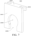
- the sealing buckle 2043 includes a base plate 20431, a limiting plate 20432, and a connecting block 20433.
- the base plate 20431 and the limiting plate 20432 are connected through the connecting block 20433.
- the connecting block 20433 is clamped in the leading wire notch 212, the limiting plate 20432 is located inside the output end of the plastic bracket 204, and the base plate 20431 is located outside the output end of the plastic bracket 204.
- the base plate 20431 is provided with a wire hole 20435, and the collection wiring harness 205 protrudes from the wiring harness groove 2041 through the wire hole 20435.
- the wiring harness groove 2041 is disposed on the main body 204a.
- the wire hardness tray 204b includes a horizontal plate 204d and a longitudinal plate 204c connected to each other.
- the longitudinal plate 204c is connected to the output end of the main body 204a, and the horizontal plate 204d is disposed on a side of the longitudinal plate 204c away from the main body 204a.
- the leading wire notch 212 is opened in the longitudinal plate 204c and communicates with the wiring harness groove 2041.
- the longitudinal plate 204c is located between the base plate 20431 and the limiting plate 20432.
- the base plate 20431 is provided with the wire hole 20435 through which the collection wiring harness 205 protrudes out of the wiring harness groove 2041 and extends into an area corresponding to the horizontal plate 204d. Furthermore, as illustrated in FIG.
- a wire inlet notch 20436 is provided on the base plate 20431, and the wire inlet notch 20436 communicates with the wire hole 20435.
- the wire inlet notch 20436 enables the collection wiring harness 205 to enter the wire hole 20435 smoothly when the sealing buckle 2043 is assembled.
- the output end of the collection wiring harness 205 extends through the leading wire notch 212 to the area corresponding to the horizontal plate 204d, and then the sealing buckle 2043 is installed on the longitudinal plate 204c, that is, at the leading wire notch 212.
- the collection wiring harness 205 is assembled into the wire hole 20435 through the wire inlet notch 20436, and then the connection block 20433 is inserted into the leading wire notch 212. It should be noted that a width of the base plate 20431 is greater than a width of the leading wire notch 212.
- the wire hole 20435 is a circular hole, which cooperates with a cloth tape (not illustrated in the figures) wrapped outside the collection wiring harness 205 to block the leading wire notch 212 while accommodating the collection wiring harness 205.
- the sealing buckle 2043 may realize the fixing the collection wiring harness 205, which may prevent the welding points of the collection wiring harness 205 from being pulled off when the output end of the collection wiring harness 205 is bound and fixed by using a cable tie 209, which improves the fastness of the fixing of the output end of the collection wiring harness 205. It should be noted that the steps of assembling the collection wiring harness 205 into the wiring harness groove 2041 and binding and fixing the output end of the collection wiring harness 205 are before the step of glue filling.
- the CCS assembly 200 further includes the above-mentioned cable ties 209 configured to bind the collection wiring harnesses 205 in the area corresponding to the horizontal plate 204d.
- a lower surface of the horizontal plate 204d is provided with a plurality limiting protrusions 215 and every two limiting protrusions 215 are arranged in groups.
- An area between the two limiting protrusions 215 defines a limiting groove configured to limit the cable tie 209, and the cable tie 209 is located in the limiting groove.
- the horizontal plate 204d is provided with first binding holes 210 each running through the horizontal plate 204d and each configured to thread the cable tie 209. In this embodiment, the limiting groove and the first binding hole 210 may prevent the cable tie 209 from shifting, and increase the stability and fastness of the cable tie 209 binding the output end of the collection wiring harness 205.
- fixing components also include wiring pressing strips 2045 arranged at the wiring harness groove 2041.
- the collection wiring harness 205 is located between a bottom of the wiring harness groove 2041 and the wiring pressing strip 2045.
- the collection wiring harness 205 includes a plurality of collection single wirings 2051, and the wiring pressing strip 2045 is provided with a through groove 2046 configured for the collection single wiring 2051 to enter the wiring harness groove 2041.
- multiple wiring pressing strips 2045 are evenly spaced along the extending direction of the wiring harness groove 2041.
- the wiring pressing strip 2045 here is arrange on a top of the wiring harness groove 2041 and configured to limit the collection wiring harness 205 on the top of the wiring harness groove 2041, so as to prevent the collection wiring harness 205 embedded in the wiring harness groove 2041 from breaking away from the wiring harness groove 2041.
- a width of the through groove 2046 is greater than or equal to an outer diameter of the collection single wiring 2051.
- the width of the through groove 2046 is slightly greater than that of the collection single wiring 2051, so that it is convenient for the collection single wiring 2051 to be assembled into the wiring harness groove 2041 through the through groove 2046, and it is also possible to prevent the collection single wiring 2051 from breaking away from the wiring harness through the through groove 2046 under non-artificial conditions.
- a length direction of the through groove 2046 and the extending direction of the wiring harness groove 2041 are arranged at an included angle.
- the included angle between the length direction of the through groove 2046 and the extending direction of the wiring harness groove 2041 ranges from 10° to 80°.
- the included angle between the length direction of the through groove 2046 and the extending direction of the wiring harness groove 2041 is 30°.
- the wiring pressing strip 2045 here may play a role of fixing the collection wiring harness 205 to a certain extent, and a structural design of the through groove 2046 makes each collection single wiring 2051 of the collection wiring harness 205 easy to comb.
- the input bar 201, the output bar 206, and the series connection bar 203 are all provided with structural weakening holes 213, which may reduce a cross-sectional area of a corresponding area, and the structural weakening holes 213 may be fused when the circuit is overloaded here, thereby playing a role of circuit protection.
- a plurality of rib plates 211 are disposed between the longitudinal plate 204c and a bottom surface of the main body 204a.
- the rib plate 211 here reinforces the longitudinal plate 204c, that is, the wiring harness tray 204b.
- a connector 400 is provided on the output ends of the collection wiring harnesses 205, and the connector 400 is configured to connect the collection wiring harnesses 205 to the BMS 300.
- This embodiment is an improvement on Embodiment 1, and repeated content will not be repeated here.
- the CCS assembly 200 includes cable ties 209 and fixing buckles, which are all configured to fix the collection wiring harnesses 205 in the area corresponding to the horizontal plate 204d.
- Each of the fixing buckles includes two binding buckles 208 correspondingly arranged, one of the two binding buckles 208 is arranged on the horizontal plate 204d, and the other one of the two binding buckles 208 is arranged on the horizontal plate 204d or the longitudinal plate 204c.
- the collection wiring harness 205 is located between the two binding buckles 208.
- Each of the binding buckles 208 includes a base 2081, and a second binding hole 2082 runs through the base 2081 and is configured to thread the cable tie 209.
- the cable tie 209 and the fixing buckle are referred to as a fixing component, where a number of fixing components is equal to the number of the collecting wiring harnesses 205, and the two are provided in one-to-one correspondence. That is to say, one fixing component corresponds to one collection wiring harness 205, which may avoid confusion of the collection single wirings 2051 of different collection wiring harnesses 205, facilitate management and layout of the collection wiring harnesses 205, and improve the efficiency of subsequent assembly of the collection wiring harnesses 205 to the connector 400.
- the left end of the plastic bracket 204 is its output end.
- the output end of the collection wiring harness 205 is close to the fixing buckle, and then the collection wiring harness 205 is tied and fixed to the fixing buckle through the cable tie 209.
- the fixing buckle here is convenient for the collection wiring harness 205 to lean against, so that it is convenient to bind and fix the collection wiring harness 205 with the cable tie 209, which may improve a structural stability of the output end of the collection wiring harness 205, and is conducive to a neat layout of the output ends of the collection wiring harnesses 205, which may further improve a subsequent battery assembly efficiency, and reduce the possibility of pulling off the welding points of the collection wiring harness 205 during the binding and assembly process.
- each collection single wiring 2051 is correspondingly embedded in the wiring harness groove 2041, and the output end of the collection single wiring 2051 first passes through a gap between the two binding buckles 208 and then extends along the front-rear direction to an appropriate position; in a third step, the cable tie 209 sequentially passes through the second binding holes 2082 corresponding to the two binding buckles 208 to bind and fix the collection wiring harness 205 in the gap between the two binding buckles 208.
- the binding buckle 208 here is convenient for the cable tie 209 to bind and fix the collection wiring harness 205.
- the horizontal plate 204d is provided with forming ports 216 each running through the horizontal plate 204d and each corresponding to the binding buckle 208.
- the wiring harness tray 204b is integrally formed with the main body 204a.
- the forming opening 216 here facilitates an injection molding of the binding buckle 208 and the wiring harness tray 204b.
- the binding buckles 208 corresponding to the two fixing buckles arranged at a rear portion of the main body 204a are all arranged on the horizontal plate 204d, and the two binding buckles 208 corresponding to the same fixing buckle are arranged in parallel.
- Each of the other four fixing buckles has the corresponding binding buckles 208, one of which is arranged on the horizontal plate 204d and the other one is arranged on the longitudinal plate 204c, which is convenient for collecting the collection wiring harnesses 205 along the front-rear direction, so as to route and tie them to approach an installation position of the BMS 300.
- an arrangement of the two binding buckles 208 constituting the same fixing buckle may be adjusted according to actual needs.
- a principle is that there is a gap between the two binding buckles 205 for accommodating the collection wiring harness 205, and it is convenient to cooperate with the cable tie 209 to bind and fix the collection wiring harness 205.
- the wiring harness tray 204b here is configured to support the collection wiring harnesses 205, which may auxiliary limit the collection wiring harnesses 205 to a certain extent, so that the staff may quickly fix the output end of the collection wiring harness 205, thereby preventing the output end of collection wiring harness 205 from interfering with a battery structure on a lower surface of the wiring harness tray 204b, while reducing the technical difficulty of fixing the output end of the collection wiring harness 205.
Landscapes
- Chemical & Material Sciences (AREA)
- Chemical Kinetics & Catalysis (AREA)
- Electrochemistry (AREA)
- General Chemical & Material Sciences (AREA)
- Battery Mounting, Suspending (AREA)
Abstract
Description
- This application claims priority to
Chinese Patent Application No. 202310456346.1, filed on April 24, 2023 Chinese Patent Application No. 202320963943.9, filed on April 24, 2023 Chinese Patent Application No. 202320963926.5, filed on April 24, 2023 - The present disclosure relates to the field of battery technologies, and in particular, to cell contact system (CCS) assemblies and battery packs.
- During the application process, batteries need to cooperate with a battery management system (BMS) to collect temperature and pressure signals to realize a battery management. A battery pack in related art mostly use a cell contact system (CCS) assembly for series and parallel connection of single batteries in the battery pack and for collections of the temperature and pressure signals.
- A conventional CCS assembly includes components such as a busbar, a bracket, and a collection wiring harness. When in operation, the components such as the busbar and the collection wiring harness are mostly integrated on the bracket. After assembled into the battery pack, glue is usually poured over the entire CCS assembly to attach the components such as aluminum bars and the collection wiring harness to the bracket.
- An upper surface of the bracket in the related art is provided with an upper accommodating groove configured to accommodate the busbar. When pouring glue, the glue is directly poured over the busbar, and the glue flows to a gap between the busbar and the upper accommodating groove to realize bonding and fixing of the two. However, a glue irrigation area of this fixing method is large, the time for the glue to flow to the gap between the busbar and the upper accommodating groove is long, the production costs is high, and the bonding efficiency is low.
- Aiming at the deficiencies of the related art, a first object of the present disclosure is to provide a CCS assembly that is easy to bond and requires less glue.
- A second object of the present disclosure is to provide a battery pack with high safety and low costs.
- According to an aspect of the present disclosure, a CCS assembly is provided, including: busbars; a plastic bracket, having an upper surface provided with upper accommodating grooves configured to accommodate the busbars, having a lower surface provided with lower accommodating grooves configured to accommodate single batteries, and the upper accommodating grooves communicating with the lower accommodating grooves to make the busbars abut against the single batteries; glue guiding grooves, disposed on the upper surface of the plastic bracket, and each of the glue guiding grooves communicating with the upper accommodating grooves adjacent thereto.
- In some embodiments, the busbars include an input bar, current guide bars, series connection bars, and an output bar, all of which are correspondingly embedded in the upper accommodating grooves; the current guide bars cooperate with the input bar and the output bar to connect every two adjacent ones of the single batteries in series in a first direction, and to connect two adjacent ones of the single batteries in parallel in a second direction; current guide groups each including a plurality of the current guide bars connected in series along the first direction are defined, and each of the series connection bars is configured to connect two adjacent ones of the current guide groups arranged along the second direction in series; and the glue guiding groove each of the glue guiding grooves extends along the first direction.
- In some embodiments, the CCS assembly further includes collection wiring harnesses, input ends of the collection wiring harnesses are electrically connected to the busbars or the single batteries; wiring harness grooves each extending along the first direction are provided on the plastic bracket, the collection wiring harnesses are embedded in the wiring harness grooves, and the wiring harness grooves are arranged in one-to-one correspondence with the current guide groups; and the wiring harness grooves are arranged adjacent to the glue guiding grooves, and each of the wiring harness grooves communicates with the glue guiding grooves adjacent thereto.
- In some embodiments, a height of a bottom inner surface of each of the glue guiding grooves is not lower than a height of a bottom inner surface of each of the wiring harness grooves.
- In some embodiments, each of the wiring harness grooves is provided with a glue discharge hole running through a bottom thereof.
- In some embodiments, branch grooves are provided on the upper surface of the plastic bracket, an extending direction of each of the branch grooves is arranged at an included angle with an extending direction of each of the wiring harness grooves; each of the branch grooves is configured to communicate with a corresponding one of the wiring harness grooves and one of the upper accommodating grooves corresponding to the corresponding one of the wiring harness grooves, collection single wirings of the collection wiring harnesses extend to the upper accommodating grooves corresponding to the collection wiring harnesses through the branch grooves; and a height of a bottom inner surface of each of glue guiding grooves is not lower than a height of a bottom inner surface of each of the branch grooves.
- In some embodiments, a height of a bottom inner surface of each of the upper accommodating grooves is not higher than the height of the bottom inner surface of each of the branch grooves; and the height of the bottom inner surface of each of the upper accommodating grooves is not higher than the height of the bottom inner surface of each of the glue guiding grooves.
- In some embodiments, both sides of each of the current guide groups along the first direction are provided with the glue guiding grooves.
- In some embodiments, each of the upper accommodating grooves includes a plurality of first grooves arranged along the first direction, each of the first grooves includes at least two installation areas arranged at intervals in the second direction, and two adjacent ones of the installation areas are communicated with each other through a second groove; and at least one of the glue guiding grooves is arranged between the two adjacent ones of the installation areas and communicates with the second groove.
- In some embodiments, an output end of the plastic bracket is provided with leading wire notches corresponding to the wiring harness grooves one by one, each of the leading wire notches communicates with a corresponding one of the wiring harness grooves, and the collection wiring harnesses protrude from the wiring harness grooves by passing through the leading wire notches; the CCS assembly further includes sealing buckles disposed on the plastic bracket and configured to seal the leading wire notches; and the collection wiring harnesses protrude from the wiring harness grooves by passing through the sealing buckles.
- In some embodiments, each of the sealing buckles includes a base plate, a limiting plate, and a connecting block, and the base plate is connected with the limiting plate through the connecting block; the connecting block is clamped in one of the leading wire notches, the limiting plate is located inside the output end of the plastic bracket, and the base plate is located outside the output end of the plastic bracket; and the base plate is provided with a wire hole, and one of the collection wiring harnesses protrudes from one of the wiring harness grooves through the wire hole.
- In some embodiments, the plastic bracket includes a main body and a wire hardness tray disposed on the output end of the plastic bracket, the wiring harness grooves, the upper accommodating grooves, and the lower accommodating grooves are all disposed on the main body; the wire hardness tray includes a horizontal plate and a longitudinal plate connected with each other, the longitudinal plate is connected to an output end of the main body, and the horizontal plate is disposed on a side of the longitudinal plate away from the main body; the leading wire notches are opened on the longitudinal plate, and the longitudinal plate is located between the base plate and the limiting plate; and the base plate is provided with a wire hole through which one of the collection wiring harnesses protrudes out of one of the wiring harness grooves and extends into an area corresponding to the horizontal plate.
- In some embodiments, the CCS assembly further includes cable ties configured to bind the collection wiring harnesses in the area corresponding to the horizontal plate; a lower surface of the horizontal plate is provided with a plurality limiting protrusions every two of which arranged in groups, an area between the every two of the limiting protrusions defines a limiting groove configured to limit one of the cable ties, and the one of the cable ties is located in the limiting groove; and the horizontal plate is provided with first binding holes each running through the horizontal plate and each configured to thread one of the cable ties.
- In some embodiments, the CCS assembly further includes cable ties and fixing buckles, which are all configured to fix the collection wiring harness in the area corresponding to horizontal plate; each of the fixing buckles includes two binding buckles correspondingly arranged, one of which is arranged on the horizontal plate, and the other one is arranged on the horizontal plate or the longitudinal plate; the two binding buckles have one of the collection wiring harnesses located therebetween; and each of the binding buckles includes a base, and a second binding hole runs through the base and configured to thread one of the cable ties.
- In some embodiments, the horizontal plate is provided with forming ports each running through the horizontal plate and each corresponding to one of the binding buckles.
- In some embodiments, wiring pressing strips are provided at each of the wiring harness grooves; the collection wiring harnesses are located between bottoms of the wiring harness grooves and the wiring pressing strips; and the collection wiring harnesses include a plurality of collection single wirings, each of the wiring pressing strips is provided with a through groove configured for the collection single wirings to enter the wiring harness grooves.
- In some embodiments, a width of the through groove is greater than or equal to an outer diameter of each of the collection single wirings.
- In some embodiments, a length direction of the through groove and an extending direction of each of the wiring harness grooves are arranged at an included angle.
- In some embodiments, the included angle between the length direction of the through groove and the extending direction of each of the wiring harness grooves ranges from 10° to 80°.
- In some embodiments, a plurality of rib plates are provided between the longitudinal plate and a bottom surface of the main body.
- According to another aspect of the present disclosure, a battery pack is provided, including the above-mentioned CCS assembly.
- The technical solutions of the embodiments of the present disclosure have at least the following advantages and beneficial effects.
- The present disclosure adopts the glue guiding grooves to drain the glue, which may accurately drain the glue into the gap between the busbars and the upper accommodating grooves, as well as the gap between the single batteries and the lower accommodating grooves, thereby preventing the glue from being coated on the upper surface of the busbars and other irrelevant areas of the plastic bracket, improving the bonding efficiency, reducing the amount of the glue on the premise of ensuring the bonding strength, and saving production costs.
-
-
FIG. 1 is a schematic structural view of a battery pack provided in Embodiment 1 of the present disclosure; -
FIG. 2 is a schematic view of an exploded structure of a CCS assembly provided in Embodiment 1 of the present disclosure; -
FIG. 3 is a partial enlarged schematic view of a structure at A inFIG. 2 ; -
FIG. 4 is a partial enlarged schematic view of a structure at B inFIG. 2 ; -
FIG. 5 is a schematic view of a three-dimensional structure of a CCS assembly provided in Embodiment 1 of the present disclosure; -
FIG. 6 is a partial enlarged schematic view of a structure at C inFIG. 5 ; -
FIG. 7 is a schematic view of a three-dimensional structure of a sealing buckle provided in Embodiment 1 of the present disclosure; -
FIG. 8 is a schematic top view of a CCS assembly provided in Embodiment 1 of the present disclosure; -
FIG. 9 is a schematic bottom view of a CCS assembly provided in Embodiment 1 of the present disclosure; -
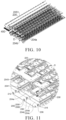
FIG. 10 is a schematic view of an exploded structure of a CCS assembly provided in Embodiment 2 of the present disclosure; -
FIG. 11 is a partial enlarged schematic view of a structure at D inFIG. 10 ; -
FIG. 12 is a schematic view of a first three-dimensional structure of a CCS assembly provided in Embodiment 2 of the present disclosure; -
FIG. 13 is a partial enlarged schematic view of a structure at E inFIG. 12 ; -
FIG. 14 is a schematic view of a second three-dimensional structure of a CCS assembly provided in Embodiment 2 of the present disclosure. - Reference numerals: 100, single battery; 200, CCS assembly; 201, input bar; 202, current guide bar; 203, series connection bar; 204, plastic bracket; 204a, main body; 204b, wire hardness tray; 204c, longitudinal plate; 204d, horizontal plate; 2041, wiring harness groove; 2042, glue guiding groove; 2043, sealing buckle; 20431, base plate; 20432, limiting plate; 20433, connecting block; 20435, wire hole; 20436, wire inlet notch; 2044, branch groove; 2045, wiring pressing strip; 2046, through groove; 2047, installation area; 2048, second groove; 205, collection wiring harness; 2051, collection single wiring; 206, output bar; 207, glue discharge hole; 208, binding buckle; 2081, base; 2082, second binding hole; 209, tie; 210, first binding hole; 211, rib plate; 212, leading wire notch; 213, structural weakening hole; 214, lower accommodating groove; 215, limiting protrusion; 216, forming port; 300, BMS; 400, connector; 500, serpentine liquid cooling plate.
- In the description of the present disclosure, it should be noted that, orientations or positional relationships indicated by the terms "upper", "lower", "front", "rear", "left", "right", "vertical", "horizontal", "top", "bottom", "inner", "outer", etc. are based on the orientations or positional relationships illustrated in the attached drawings, and are only for the convenience of describing the present disclosure and simplifying the description, rather than indicating or implying that the referred devices or elements have certain orientations, or are constructed or operated in certain orientations, and thus should not be construed as limitations on the present disclosure.
- In the description of the present disclosure, unless otherwise clearly stipulated and limited, the terms "first" and "second" are only configured for the purpose of description, and cannot be understood as indicating or implying relative importance. The term "plurality" means two or more. The term "and/or" includes any and all combinations of one or more of the associated listed items. In particular, references to "the" object or "an/a" object are likewise intended to represent one of several such objects that may be possible.
- Furthermore, in the description of the present disclosure, it should be understood that the referenced orientation terms such as "on", "below", "inside", and "outside" are described from the perspective illustrated in the drawings, should not be construed as a limitation to specific embodiments. It also needs to be understood that in the context, when a component or feature is referred to as being "on" "below", "inside", or "outside" another component(s), it cannot only be directly connected "on" "below", "inside", or "outside" another (one or more) components, it can also be indirectly connected "on" "below", "inside", or "outside" another (one or more) components through intermediate components.
- Referring to
FIG. 1 to FIG. 9 , aCCS assembly 200 should be configured as cylindrical power battery modules, including busbars, aplastic bracket 204, andglue guiding grooves 2042. Herein, an upper surface of theplastic bracket 204 is provided with upper accommodating grooves configuration to accommodate the busbars, a lower surface of theplastic bracket 204 is provided with loweraccommodating grooves 214 configured to accommodate thesingle batteries 100 of the cylindrical power battery modules, and the upper accommodating groove and the loweraccommodating groove 214 communicate with each other to make the busbars abut against thesingle batteries 100. Theglue guiding grooves 2042 are arranged on the upper surface of theplastic bracket 204, and each of theglue guiding grooves 2042 communicates with the upper accommodating groove adjacent thereto. In an embodiment, as illustrated inFIG. 3 and FIG. 4 , theplastic bracket 204 here includes amain body 204a and awiring harness tray 204b disposed at an output end of themain body 204a. The upper accommodating grooves and the loweraccommodating grooves 214 are all arranged on themain body 204a. Themain body 204a here has a plate shape. A shape of the upper accommodating groove is adapted to a shape of the busbar. When in operation, the busbars are first assembled into the upper accommodating grooves, and theplastic bracket 204 is attached to thesingle batteries 100, that is to say, thesingle batteries 100 are assembled into the loweraccommodating grooves 214, and then glue is poured into theglue guiding grooves 2042, and the glue in theglue guiding grooves 2042 flows along theglue guiding grooves 2042 to the upper accommodation grooves at this time, that is, the glue in theglue guiding grooves 2042 flows along theglue guiding grooves 2042 to a gap between the busbars and the upper accommodation grooves, so as to realize the bonding and fixing of the busbar and theplastic bracket 204. At the same time, because the upper accommodating grooves and the loweraccommodating grooves 214 are communicated, excess glue in the upper accommodating grooves flows to a gap between the loweraccommodating grooves 214 and the single batteries to realize bonding and fixing between theplastic bracket 204 and thesingle batteries 100. In this embodiment, a bonding strength between the busbar and theplastic bracket 204 depends on a bonding area between the busbar and the upper accommodating groove, and a bonding strength between theplastic bracket 204 and thesingle battery 100 depends on a bonding area between theplastic bracket 204 and thesingle battery 100. Therefore, compared with a conventional glue pouring method, this embodiment adopts theglue guiding grooves 2042 to drain the glue, which may accurately drain the glue into the gap between the busbars and the upper accommodating grooves, as well as the gap between thesingle batteries 100 and the loweraccommodating grooves 214, thereby preventing the glue from being coated on the upper surface of the busbars and other irrelevant areas of theplastic bracket 204, improving the bonding efficiency, reducing the amount of the glue on the premise of ensuring the bonding strength, and saving production costs. - The above-mentioned glue is a heat-conducting gel, which realizes the fixing between the components of the
CCS assembly 200 and the fixing between theCCS assembly 200 and thesingle battery 100, and at the same time improves a heat dissipation efficiency of the battery. - As illustrated in
FIG. 1 andFIG. 8 , the busbars include aninput bar 201, current guide bars 202, series connection bars 203, and anoutput bar 206. All of theinput bar 201, the current guide bars 202, the series connection bars 203, and theoutput bar 206 are correspondingly embedded in the upper accommodating grooves. The current guide bars 202 cooperate with theinput bar 201 and theoutput bar 206 to connect every two adjacentsingle batteries 100 arranged in a first direction in series; and the current guide bars 202 cooperate with theinput bar 201 and theoutput bar 206 to connect every two adjacentsingle batteries 100 arranged in a second direction in parallel. That is, the current guide bars 202 are configured to cooperate with theinput bar 201 and theoutput bar 206 to connect every two adjacentsingle batteries 100 arranged along the first direction in series and connect every two adjacentsingle batteries 100 arranged along the second direction in parallel. A plurality of current guide bars 202 connected in series along the first direction are defined as a current guide group, and each of the series connection bars 203 is configured to connect two adjacent current guide groups arranged along the second direction in series. Theglue guiding groove 2042 extends along the first direction. In this embodiment, the first direction is the left-right direction, and the second direction is the front-rear direction. Furthermore, the cylindrical power battery in this embodiment is composed of six cylindrical power battery modules arranged in series in the front-rear direction, that is, in the second direction. Each single cylindrical power battery module includes a plurality ofsingle batteries 100 connected in series in the left-right direction, that is, in the first direction, multiplesingle batteries 100 connected in series in the left-right direction is defined as a battery row, and each cylindrical power battery module includes two battery rows connected in parallel in the front-rear direction. Thecurrent guide bar 202 here is configured to connect two adjacentsingle batteries 100 arranged in the left-right direction in series, and connect two adjacentsingle batteries 100 arranged in a same cylindrical power battery module and in the front-rear direction in parallel. Theseries connection bar 203 is configured to connect two adjacent cylindrical power battery modules in series. Electrical connections between thesingle batteries 100 of the cylindrical power battery modules and theinput bar 201, the current guide bars 202, the series connection bars 203, and theoutput bar 206, and assembly modes of theinput bar 201, the current guide bars 202, the series connection bars 203, and theoutput bar 206 fitted with theplastic bracket 204 belong to related art, and will not be repeated here. A structure of theglue guiding groove 2042 extending along the first direction enables the sameglue guiding groove 2042 to connect multiple upper accommodation grooves in series in the first direction, that is, in the left-right direction, which is beneficial to improve the efficiency of glue filling and bonding. - As illustrated in
FIG. 2 ,FIG. 4 , andFIG. 8 , theCCS assembly 200 further includes collection wiring harnesses 205. An input end of thecollection wiring harness 205 is electrically connected to the busbar or thesingle batteries 100.Wiring harness grooves 2041 each extending along the first direction are provided on theplastic bracket 204. Thecollection wiring harness 205 is embedded in thewiring harness groove 2041, and thewiring harness grooves 2041 are arranged in one-to-one correspondence with the current guide groups. Thewiring harness grooves 2041 are arranged adjacent to theglue guiding grooves 2042, and thewiring harness groove 2041 communicates with theglue guiding groove 2042 adjacent thereto. In this embodiment, the input end of thecollection wiring harness 205 is connected to at least one of theinput bar 201, theoutput bar 206, thecurrent guide bar 202, theseries connection bar 203, and thesingle battery 100. In this embodiment, a number of the collection wiring harnesses 205 is six, which are set in one-to-one correspondence with the six cylindrical power battery modules. In this embodiment, the collectionsingle wirings 2051 that make up thecollection wiring harness 205 are welded to the busbar of the cylindrical power battery module corresponding to thecollection wiring harness 205, so as to realize a comprehensive monitoring of temperature and pressure signals of the cylindrical power battery module. Thewiring harness groove 2041 here facilitates the wiring of the collectionsingle wirings 2051 that forming thecollection wiring harness 205, which may avoid winding and knotting of each collectionsingle wiring 2051 during a welding process of the collectionsingle wiring 2051 and the busbar, which is conducive to improving work efficiency. At the same time, by housing the collection wiring harnesses 205 in thewiring harness grooves 2041, an auxiliary fixing of the collection wiring harnesses 205 may be realized before coating the glue, and the glue in theglue guiding grooves 2042 may flow into thewiring harness grooves 2041 to realize the fixing of the collection wiring harnesses 205 during a glue coating stage, which may effectively improve a fastness of the fixing of the collection wiring harnesses 205. Furthermore, a structural design of thewiring harness grooves 2041 may reduce a thickness of theCCS assembly 200, which is conducive to reducing a volume of the cylindrical power battery and improving an energy density of the cylindrical power battery. - Preferably, a height of a bottom inner surface of the
glue guiding groove 2042 is not lower than a height of a bottom inner surface of thewiring harness groove 2041, so that it is convenient for the glue in theglue guiding groove 2042 to flow into thewiring harness groove 2041. At the same time, thewiring harness grooves 2041 here may also play a role of storing excess glue and fixing serpentineliquid cooling plates 500. In an embodiment, as illustrated inFIG. 1 andFIG. 9 , the battery pack provided in the embodiments includes theCCS assembly 200 and the battery modules in the embodiments. The battery pack here is specifically a cylindrical power battery pack, which is composed of six cylindrical power battery modules. The battery pack also includes the above-mentioned serpentineliquid cooling plates 500, a number of the serpentineliquid cooling plates 500 is six, and the serpentineliquid cooling plates 500 are arranged in one-to-one correspondence with the sixwiring harness grooves 2041. Thewiring harness groove 2041 is provided with aglue discharge hole 207 running through a bottom thereof. After the glue enters thewiring harness groove 2041, part of the glue flows from theglue discharge hole 207 to an underside of theplastic bracket 204, and to a gap between a bottom outer surface of thewiring harness groove 2041 and the serpentineliquid cooling plate 500, so that the serpentineliquid cooling plate 500 and thesingle battery 100, and the serpentineliquid cooling plate 500 and theplastic bracket 204 are bonded and fixed. - As illustrated in
FIG. 4 to FIG. 6 , the upper surface of theplastic bracket 204 is provided withbranch grooves 2044. An extending direction of thebranch groove 2044 is arranged at an included angle with an extending direction of thewiring harness groove 2041. Thebranch groove 2044 is configured to communicate with thewiring harness groove 2041 and the upper accommodating groove corresponding to thewiring harness groove 2041, and the collectionsingle wirings 2051 of thecollection wiring harness 205 extend to the upper accommodating groove corresponding to the collectionsingle wiring 2051 through thebranch groove 2044. The height of the bottom inner surface of theglue guiding groove 2042 is not lower than a height of a bottom inner surface of thebranch groove 2044. In this embodiment, in a first aspect, an included angle between the extending direction of thebranch groove 2044 and the extending direction of thewiring harness groove 2041 is 90°, and the glue in theglue guiding grooves 2042 enters the upper accommodating grooves through thebranch grooves 2044 to play the role of drainage; in a second aspect, the collectionsingle wiring 2051 stored in thebranch groove 2044 is bonded and fixed with thebranch groove 2044 by the glue flowing through thebranch groove 2044, which has strong firmness and may reduce the possibility of the collectionsingle wiring 2051 shaking during the operation of the battery pack, thereby ensuring the solidity of welding points between the collectionsingle wiring 2051 and the busbar, and high safety. In an embodiment, the bottom inner surface of theglue guiding groove 2042 is higher than the bottom inner surface of thebranch groove 2044. - In an embodiment, a height of a bottom inner surface of the upper accommodating groove is not higher than the height of the bottom inner surface of the
branch groove 2044, and the height of the bottom inner surface of the upper accommodating groove is not higher than the height of the bottom inner surface of theglue guiding groove 2042, which is convenient for the glue in theglue guiding grooves 2042 to flow to the upper accommodating grooves, which is beneficial to improve the glue pouring efficiency. - As illustrated in
FIG. 4 , furthermore, in order to improve the glue pouring efficiency and the quality of gluing, both sides of the current guide group along the first direction are provided with theglue guiding grooves 2042. - In this embodiment, as illustrated in
FIG. 4 andFIG. 8 , in order to further improve the glue pouring efficiency and the quality of gluing, each of the upper accommodating grooves includes a plurality of first grooves arranged along the first direction. Each of the first grooves includes at least twoinstallation areas 2047 arranged at intervals in the second direction, and the twoadjacent installation areas 2047 are communicated with each other through asecond groove 2048. At least oneglue guiding groove 2042 is disposed between the twoadjacent installation areas 2047, and theglue guiding groove 2042 communicates with thesecond groove 2048. A number of theinstallation areas 2047 of the first groove here is two, and oneglue guiding groove 2042 extending along the first direction is arranged between the twoinstallation areas 2047. In this embodiment, the first groove is configured to accommodate thecurrent guide bar 202. - In this embodiment, the output end of the
plastic bracket 204 is provided withleading wire notches 212 corresponding to thewiring harness grooves 2041 one by one. Theleading wire notch 212 communicates with the correspondingwiring harness groove 2041, and thecollection wiring harness 205 protrudes from thewiring harness groove 2041 by passing through theleading wire notch 212. TheCCS assembly 200 further includes sealingbuckles 2043 disposed on theplastic bracket 204 and configured to seal theleading wire notches 212. Thecollection wiring harness 205 protrudes from thewiring harness groove 2041 by passing through thesealing buckle 2043. In this embodiment, the output end of theplastic bracket 204 is an end close to aBMS 300, specifically the left end as illustrated inFIG. 1 . In a first aspect, thesealing buckle 2043 here may fix the output end of thecollection wiring harness 205 to a certain extent, thereby preventing the welding points between thecollection wiring harness 205 and the busbar from being pulled off since thecollection wiring harness 205 is pulled during the components are assembled before glue filling. In a second aspect, thesealing buckle 2043 may cooperate with thewiring harness groove 2041 to reduce a wiring height of thecollection wiring harness 205, which is beneficial to reduce the thickness of theCCS assembly 200, thereby reducing the volume of the battery pack and increasing the energy density of the battery pack. In the third aspect, thesealing buckle 2043 may seal theleading wire notch 212, that is, thewiring harness groove 2041, which prevents the glue in thewiring harness groove 2041 from overflowing. - In an embodiment, as illustrated in
FIG. 7 , thesealing buckle 2043 includes abase plate 20431, a limitingplate 20432, and a connectingblock 20433. Thebase plate 20431 and the limitingplate 20432 are connected through the connectingblock 20433. The connectingblock 20433 is clamped in theleading wire notch 212, the limitingplate 20432 is located inside the output end of theplastic bracket 204, and thebase plate 20431 is located outside the output end of theplastic bracket 204. Thebase plate 20431 is provided with awire hole 20435, and thecollection wiring harness 205 protrudes from thewiring harness groove 2041 through thewire hole 20435. In an embodiment, thewiring harness groove 2041 is disposed on themain body 204a. Thewire hardness tray 204b includes ahorizontal plate 204d and alongitudinal plate 204c connected to each other. Thelongitudinal plate 204c is connected to the output end of themain body 204a, and thehorizontal plate 204d is disposed on a side of thelongitudinal plate 204c away from themain body 204a. Theleading wire notch 212 is opened in thelongitudinal plate 204c and communicates with thewiring harness groove 2041. Thelongitudinal plate 204c is located between thebase plate 20431 and the limitingplate 20432. Thebase plate 20431 is provided with thewire hole 20435 through which thecollection wiring harness 205 protrudes out of thewiring harness groove 2041 and extends into an area corresponding to thehorizontal plate 204d. Furthermore, as illustrated inFIG. 7 , awire inlet notch 20436 is provided on thebase plate 20431, and thewire inlet notch 20436 communicates with thewire hole 20435. Thewire inlet notch 20436 enables thecollection wiring harness 205 to enter thewire hole 20435 smoothly when thesealing buckle 2043 is assembled. - When in operation, the output end of the
collection wiring harness 205 extends through theleading wire notch 212 to the area corresponding to thehorizontal plate 204d, and then thesealing buckle 2043 is installed on thelongitudinal plate 204c, that is, at theleading wire notch 212. In this process, thecollection wiring harness 205 is assembled into thewire hole 20435 through thewire inlet notch 20436, and then theconnection block 20433 is inserted into theleading wire notch 212. It should be noted that a width of thebase plate 20431 is greater than a width of theleading wire notch 212. Thewire hole 20435 is a circular hole, which cooperates with a cloth tape (not illustrated in the figures) wrapped outside thecollection wiring harness 205 to block theleading wire notch 212 while accommodating thecollection wiring harness 205. At the same time, thesealing buckle 2043 may realize the fixing thecollection wiring harness 205, which may prevent the welding points of thecollection wiring harness 205 from being pulled off when the output end of thecollection wiring harness 205 is bound and fixed by using acable tie 209, which improves the fastness of the fixing of the output end of thecollection wiring harness 205. It should be noted that the steps of assembling thecollection wiring harness 205 into thewiring harness groove 2041 and binding and fixing the output end of thecollection wiring harness 205 are before the step of glue filling. - In an embodiment, as illustrated in
FIG. 6 andFIG. 9 , in this embodiment, theCCS assembly 200 further includes the above-mentionedcable ties 209 configured to bind the collection wiring harnesses 205 in the area corresponding to thehorizontal plate 204d. A lower surface of thehorizontal plate 204d is provided with aplurality limiting protrusions 215 and every two limitingprotrusions 215 are arranged in groups. An area between the two limitingprotrusions 215 defines a limiting groove configured to limit thecable tie 209, and thecable tie 209 is located in the limiting groove. Thehorizontal plate 204d is provided with firstbinding holes 210 each running through thehorizontal plate 204d and each configured to thread thecable tie 209. In this embodiment, the limiting groove and the firstbinding hole 210 may prevent thecable tie 209 from shifting, and increase the stability and fastness of thecable tie 209 binding the output end of thecollection wiring harness 205. - In this embodiment, fixing components also include wiring
pressing strips 2045 arranged at thewiring harness groove 2041. Thecollection wiring harness 205 is located between a bottom of thewiring harness groove 2041 and thewiring pressing strip 2045. Thecollection wiring harness 205 includes a plurality of collectionsingle wirings 2051, and thewiring pressing strip 2045 is provided with a throughgroove 2046 configured for the collectionsingle wiring 2051 to enter thewiring harness groove 2041. In this embodiment, multiple wiringpressing strips 2045 are evenly spaced along the extending direction of thewiring harness groove 2041. The wiringpressing strip 2045 here is arrange on a top of thewiring harness groove 2041 and configured to limit thecollection wiring harness 205 on the top of thewiring harness groove 2041, so as to prevent thecollection wiring harness 205 embedded in thewiring harness groove 2041 from breaking away from thewiring harness groove 2041. - In this embodiment, a width of the through
groove 2046 is greater than or equal to an outer diameter of the collectionsingle wiring 2051. Preferably, the width of the throughgroove 2046 is slightly greater than that of the collectionsingle wiring 2051, so that it is convenient for the collectionsingle wiring 2051 to be assembled into thewiring harness groove 2041 through the throughgroove 2046, and it is also possible to prevent the collectionsingle wiring 2051 from breaking away from the wiring harness through the throughgroove 2046 under non-artificial conditions. - Optionally, a length direction of the through
groove 2046 and the extending direction of thewiring harness groove 2041 are arranged at an included angle. In an embodiment, the included angle between the length direction of the throughgroove 2046 and the extending direction of thewiring harness groove 2041 ranges from 10° to 80°. In this embodiment, preferably, the included angle between the length direction of the throughgroove 2046 and the extending direction of thewiring harness groove 2041 is 30°. The wiringpressing strip 2045 here may play a role of fixing thecollection wiring harness 205 to a certain extent, and a structural design of the throughgroove 2046 makes each collectionsingle wiring 2051 of thecollection wiring harness 205 easy to comb. - In this embodiment, the
input bar 201, theoutput bar 206, and theseries connection bar 203 are all provided with structural weakening holes 213, which may reduce a cross-sectional area of a corresponding area, and the structural weakening holes 213 may be fused when the circuit is overloaded here, thereby playing a role of circuit protection. - In this embodiment, as illustrated in
FIG. 9 , a plurality ofrib plates 211 are disposed between thelongitudinal plate 204c and a bottom surface of themain body 204a. Therib plate 211 here reinforces thelongitudinal plate 204c, that is, thewiring harness tray 204b. - In this embodiment, a
connector 400 is provided on the output ends of the collection wiring harnesses 205, and theconnector 400 is configured to connect the collection wiring harnesses 205 to theBMS 300. - This embodiment is an improvement on Embodiment 1, and repeated content will not be repeated here.
- Referring to
FIG. 10 to FIG. 14 , theCCS assembly 200 includescable ties 209 and fixing buckles, which are all configured to fix the collection wiring harnesses 205 in the area corresponding to thehorizontal plate 204d. Each of the fixing buckles includes twobinding buckles 208 correspondingly arranged, one of the twobinding buckles 208 is arranged on thehorizontal plate 204d, and the other one of the twobinding buckles 208 is arranged on thehorizontal plate 204d or thelongitudinal plate 204c. Thecollection wiring harness 205 is located between the twobinding buckles 208. Each of the bindingbuckles 208 includes abase 2081, and a secondbinding hole 2082 runs through thebase 2081 and is configured to thread thecable tie 209. In this embodiment, for the convenience of description, thecable tie 209 and the fixing buckle are referred to as a fixing component, where a number of fixing components is equal to the number of the collecting wiring harnesses 205, and the two are provided in one-to-one correspondence. That is to say, one fixing component corresponds to onecollection wiring harness 205, which may avoid confusion of the collectionsingle wirings 2051 of different collection wiring harnesses 205, facilitate management and layout of the collection wiring harnesses 205, and improve the efficiency of subsequent assembly of the collection wiring harnesses 205 to theconnector 400. - In an embodiment, the left end of the
plastic bracket 204 is its output end. When in operation, after the collectionsingle wirings 2051 of thecollection wiring harness 205 are welded to the busbar or the single batteries, the output end of thecollection wiring harness 205 is close to the fixing buckle, and then thecollection wiring harness 205 is tied and fixed to the fixing buckle through thecable tie 209. The fixing buckle here is convenient for thecollection wiring harness 205 to lean against, so that it is convenient to bind and fix thecollection wiring harness 205 with thecable tie 209, which may improve a structural stability of the output end of thecollection wiring harness 205, and is conducive to a neat layout of the output ends of the collection wiring harnesses 205, which may further improve a subsequent battery assembly efficiency, and reduce the possibility of pulling off the welding points of thecollection wiring harness 205 during the binding and assembly process. - Furthermore, when in operation, in a first step, the input end of the collection
single wiring 2051 is electrically connected to the corresponding cylindrical power battery module; in a second step, each collectionsingle wiring 2051 is correspondingly embedded in thewiring harness groove 2041, and the output end of the collectionsingle wiring 2051 first passes through a gap between the twobinding buckles 208 and then extends along the front-rear direction to an appropriate position; in a third step, thecable tie 209 sequentially passes through the secondbinding holes 2082 corresponding to the twobinding buckles 208 to bind and fix thecollection wiring harness 205 in the gap between the twobinding buckles 208. Thebinding buckle 208 here is convenient for thecable tie 209 to bind and fix thecollection wiring harness 205. - The
horizontal plate 204d is provided with formingports 216 each running through thehorizontal plate 204d and each corresponding to thebinding buckle 208. Thewiring harness tray 204b is integrally formed with themain body 204a. The formingopening 216 here facilitates an injection molding of thebinding buckle 208 and thewiring harness tray 204b. In an embodiment, as illustrated inFIG. 5 ,FIG. 11 , andFIG. 14 , in this embodiment, the bindingbuckles 208 corresponding to the two fixing buckles arranged at a rear portion of themain body 204a are all arranged on thehorizontal plate 204d, and the twobinding buckles 208 corresponding to the same fixing buckle are arranged in parallel. Each of the other four fixing buckles has the correspondingbinding buckles 208, one of which is arranged on thehorizontal plate 204d and the other one is arranged on thelongitudinal plate 204c, which is convenient for collecting the collection wiring harnesses 205 along the front-rear direction, so as to route and tie them to approach an installation position of theBMS 300. Of course, in other embodiments, an arrangement of the twobinding buckles 208 constituting the same fixing buckle may be adjusted according to actual needs. A principle is that there is a gap between the twobinding buckles 205 for accommodating thecollection wiring harness 205, and it is convenient to cooperate with thecable tie 209 to bind and fix thecollection wiring harness 205. Thewiring harness tray 204b here is configured to support the collection wiring harnesses 205, which may auxiliary limit the collection wiring harnesses 205 to a certain extent, so that the staff may quickly fix the output end of thecollection wiring harness 205, thereby preventing the output end ofcollection wiring harness 205 from interfering with a battery structure on a lower surface of thewiring harness tray 204b, while reducing the technical difficulty of fixing the output end of thecollection wiring harness 205.
Claims (21)
- A cell contact system (CCS) assembly, comprising:busbars;a plastic bracket (204), having an upper surface provided with upper accommodating grooves configured to accommodate the busbars, and having a lower surface provided with lower accommodating grooves (214) configured to accommodate single batteries (100), wherein the upper accommodating grooves and the lower accommodating grooves (214) are communicated to make the busbars abut against the single batteries (100); andglue guiding grooves (2042), disposed on the upper surface of the plastic bracket (204), wherein each of the glue guiding grooves (2042) communicates with the upper accommodating grooves adjacent thereto.
- The CCS assembly according to claim 1, wherein the busbars comprise an input bar (201), current guide bars (202), series connection bars (203), and an output bar (206), all of which are correspondingly embedded in the upper accommodating grooves;the current guide bars (202) cooperate with the input bar (201) and the output bar (206) to connect every two adjacent ones of the single batteries (100) in series in a first direction, and to connect two adjacent ones of the single batteries (100) in parallel in a second direction;current guide groups each comprising a plurality of the current guide bars (202) connected in series along the first direction are defined, and each of the series connection bars (203) is configured to connect two adjacent ones of the current guide groups arranged along the second direction in series; andeach of the glue guiding grooves (2042) extends along the first direction.
- The CCS assembly according to claim 2, further comprising collection wiring harnesses (205), wherein input ends of the collection wiring harnesses (205) are electrically connected to the busbars or the single batteries (100);wiring harness grooves (2041) each extending along the first direction are provided on the plastic bracket (204), the collection wiring harnesses (205) are embedded in the wiring harness grooves (2041), and the wiring harness grooves (2041) are arranged in one-to-one correspondence with the current guide groups; andthe wiring harness grooves (2041) are arranged adjacent to the glue guiding grooves (2042), and each of the wiring harness grooves (2041) communicates with the glue guiding grooves (2042) adjacent thereto.
- The CCS assembly according to claim 3, wherein a height of a bottom inner surface of each of the glue guiding grooves (2042) is not lower than a height of a bottom inner surface of each of the wiring harness grooves (2041).
- The CCS assembly according to claim 3, wherein each of the wiring harness grooves (2041) is provided with a glue discharge hole (207) running through a bottom thereof.
- The CCS assembly according to claim 3, wherein branch grooves (2044) are provided on the upper surface of the plastic bracket (204), an extending direction of each of the branch grooves (2044) is arranged at an included angle with an extending direction of each of the wiring harness grooves (2041);each of the branch grooves (2044) is configured to communicate with a corresponding one of the wiring harness grooves (2041) and one of the upper accommodating grooves corresponding to the corresponding one of the wiring harness grooves (2041), collection single wirings (2051) of the collection wiring harnesses (205) extend to the upper accommodating grooves corresponding to the collection wiring harnesses (205) through the branch grooves (2044); anda height of a bottom inner surface of each of glue guiding grooves (2042) is not lower than a height of a bottom inner surface of each of the branch grooves (2044).
- The CCS assembly according to claim 6, wherein a height of a bottom inner surface of each of the upper accommodating grooves is not higher than the height of the bottom inner surface of each of the branch grooves (2044); and
the height of the bottom inner surface of each of the upper accommodating grooves is not higher than the height of the bottom inner surface of each of the glue guiding grooves (2042). - The CCS assembly according to any one of claim 2 to claim 7, wherein both sides of each of the current guide groups along the first direction are provided with the glue guiding grooves (2042).
- The CCS assembly according to claim 8, wherein each of the upper accommodating grooves comprises a plurality of first grooves arranged along the first direction, each of the first grooves comprises at least two installation areas (2047) arranged at intervals in the second direction, and two adjacent ones of the installation areas (2047) are communicated with each other through a second groove (2048); and
at least one of the glue guiding grooves (2042) is arranged between the two adjacent ones of the installation areas (2047) and communicates with the second groove (2048). - The CCS assembly according to any one of claim 3 to claim 7, wherein an output end of the plastic bracket (204) is provided with leading wire notches (212) corresponding to the wiring harness grooves (2041) one by one, each of the leading wire notches (212) communicates with a corresponding one of the wiring harness grooves (2041), and the collection wiring harnesses (205) protrude from the wiring harness grooves (2041) by passing through the leading wire notches (212);the CCS assembly (200) further comprises sealing buckles (2043) disposed on the plastic bracket (204) and configured to seal the leading wire notches (212); andthe collection wiring harnesses (205) protrude from the wiring harness grooves (2041) by passing through the sealing buckles (2043).
- The CCS assembly according to claim 10, wherein each of the sealing buckles (2043) comprises a base plate (20431), a limiting plate (20432), and a connecting block (20433), and the base plate (20431) is connected with the limiting plate (20432) through the connecting block (20433);the connecting block (20433) is clamped in one of the leading wire notches (212), the limiting plate (20432) is located inside the output end of the plastic bracket (204), and the base plate (20431) is located outside the output end of the plastic bracket (204); andthe base plate (20431) is provided with a wire hole (20435), and one of the collection wiring harnesses (205) protrudes from one of the wiring harness grooves (2041) through the wire hole (20435).
- The CCS assembly according to claim 11, wherein the plastic bracket (204) comprises a main body (204a) and a wire hardness tray (204b) disposed on the output end of the plastic bracket (204), the wiring harness grooves (2041), the upper accommodating grooves, and the lower accommodating grooves (214) are all disposed on the main body (204a);the wire hardness tray (204b) comprises a horizontal plate (204d) and a longitudinal plate (204c) connected with each other, the longitudinal plate (204c) is connected to an output end of the main body (204a), and the horizontal plate (204d) is disposed on a side of the longitudinal plate (204c) away from the main body (204a);the leading wire notches (212) are opened on the longitudinal plate (204c), and the longitudinal plate (204c) is located between the base plate (20431) and the limiting plate (20432); andthe base plate (20431) is provided with a wire hole (20435) through which one of the collection wiring harnesses (205) protrudes out of one of the wiring harness grooves (2041) and extends into an area corresponding to the horizontal plate (204d).
- The CCS assembly according to claim 12, further comprising cable ties (209) configured to bind the collection wiring harnesses (205) in the area corresponding to the horizontal plate (204d),wherein a lower surface of the horizontal plate (204d) is provided with a plurality limiting protrusions (215) every two of which arranged in groups, an area between the every two of the limiting protrusions (215) defines a limiting groove configured to limit one of the cable ties (209), and the one of the cable ties (209) is located in the limiting groove; andthe horizontal plate (204d) is provided with first binding holes (2130) each running through the horizontal plate (204d) and each configured to thread one of the cable ties (209).
- The CCS assembly according to claim 12, further comprising cable ties (209) and fixing buckles, which are all configured to fix the collection wiring harness (205) in the area corresponding to horizontal plate (204d),wherein each of the fixing buckles comprises two binding buckles (208) correspondingly arranged, one of which is arranged on the horizontal plate (204d), and the other one is arranged on the horizontal plate (204d) or the longitudinal plate (204c);the two binding buckles (208) have one of the collection wiring harnesses (205) located therebetween; andeach of the binding buckles (208) comprises a base (2081), and a second binding hole (2082) runs through the base (2081) and configured to thread one of the cable ties (209).
- The CCS assembly according to claim 14, wherein the horizontal plate (204d) is provided with forming ports (216) each running through the horizontal plate (204d) and each corresponding to one of the binding buckles (208).
- The CCS assembly according to any one of claim 3 to claim 7 and claim 11 to claim 15, wherein wiring pressing strips (2045) are provided at each of the wiring harness grooves (2041);the collection wiring harnesses (205) are located between bottoms of the wiring harness grooves (2041) and the wiring pressing strips (2045); andthe collection wiring harnesses (205) comprise a plurality of collection single wirings (2051), each of the wiring pressing strips (2045) is provided with a through groove (2046) configured for the collection single wirings (2051) to enter the wiring harness grooves (2041).
- The CCS assembly according to claim 16, wherein a width of the through groove (2046) is greater than or equal to an outer diameter of each of the collection single wirings (2051).
- The CCS assembly according to claim 16, wherein a length direction of the through groove (2046) and an extending direction of each of the wiring harness grooves (2041) are arranged at an included angle.
- The CCS assembly according to claim 18, wherein the included angle between the length direction of the through groove (2046) and the extending direction of each of the wiring harness grooves (2041) ranges from 10° to 80°.
- The CCS assembly according to claim 14, wherein a plurality of rib plates (211) are provided between the longitudinal plate (204c) and a bottom surface of the main body (204a).
- A battery pack, comprising the CCS assembly (200) according to any one of claim 1 to claim 20.
Applications Claiming Priority (4)
| Application Number | Priority Date | Filing Date | Title |
|---|---|---|---|
| CN202320963926.5U CN219873929U (en) | 2023-04-24 | 2023-04-24 | CCS assembly and cylindrical power battery |
| CN202310456346.1A CN116826318B (en) | 2023-04-24 | 2023-04-24 | CCS assembly and battery pack |
| CN202320963943.9U CN219873948U (en) | 2023-04-24 | 2023-04-24 | CCS assembly and battery pack |
| PCT/CN2023/095745 WO2024221520A1 (en) | 2023-04-24 | 2023-05-23 | Ccs assembly and battery pack |
Publications (2)
| Publication Number | Publication Date |
|---|---|
| EP4475279A1 true EP4475279A1 (en) | 2024-12-11 |
| EP4475279A4 EP4475279A4 (en) | 2025-04-09 |
Family
ID=92108629
Family Applications (1)
| Application Number | Title | Priority Date | Filing Date |
|---|---|---|---|
| EP23783289.4A Pending EP4475279A4 (en) | 2023-04-24 | 2023-05-23 | Ccs assembly and battery pack |
Country Status (3)
| Country | Link |
|---|---|
| US (1) | US20250096426A1 (en) |
| EP (1) | EP4475279A4 (en) |
| WO (1) | WO2024221520A1 (en) |
Family Cites Families (8)
| Publication number | Priority date | Publication date | Assignee | Title |
|---|---|---|---|---|
| CN107968171A (en) * | 2017-11-16 | 2018-04-27 | 力神动力电池系统有限公司 | A kind of modular battery module |
| CN113597707B (en) * | 2020-06-18 | 2023-11-21 | 东莞新能安科技有限公司 | Battery modules and battery packs |
| CN113300036A (en) * | 2021-05-19 | 2021-08-24 | 安徽江淮汽车集团股份有限公司 | Battery module, integrated battery module and car |
| CN215989027U (en) * | 2021-07-22 | 2022-03-08 | 宁德时代新能源科技股份有限公司 | Battery and power consumption device |
| CN114976503A (en) * | 2022-06-17 | 2022-08-30 | 湖北亿纬动力有限公司 | CCS assembly, battery module structure and battery |
| CN217788725U (en) * | 2022-06-17 | 2022-11-11 | 湖北亿纬动力有限公司 | CCS subassembly and battery package |
| CN218039700U (en) * | 2022-07-14 | 2022-12-13 | 湖北亿纬动力有限公司 | A battery signal harness acquisition component and battery module |
| CN218041208U (en) * | 2022-07-14 | 2022-12-13 | 湖北亿纬动力有限公司 | a collection structure |
-
2023
- 2023-05-23 US US18/286,593 patent/US20250096426A1/en active Pending
- 2023-05-23 WO PCT/CN2023/095745 patent/WO2024221520A1/en not_active Ceased
- 2023-05-23 EP EP23783289.4A patent/EP4475279A4/en active Pending
Also Published As
| Publication number | Publication date |
|---|---|
| US20250096426A1 (en) | 2025-03-20 |
| WO2024221520A1 (en) | 2024-10-31 |
| EP4475279A4 (en) | 2025-04-09 |
Similar Documents
| Publication | Publication Date | Title |
|---|---|---|
| CN116826318B (en) | CCS assembly and battery pack | |
| KR102901178B1 (en) | Battery pack and vehicle comprising the battery pack | |
| CN108520928A (en) | A kind of electric automobile power battery module and electric vehicle | |
| KR102323390B1 (en) | Electricity storage battery and corresponding thermal regulation element | |
| CN108847509A (en) | A kind of cooling structure and battery modules | |
| CN117374463A (en) | Battery liquid cooling plate system and battery pack | |
| CN103247772B (en) | Battery connector | |
| CN215644849U (en) | Support frames and battery modules for battery modules | |
| CN206022575U (en) | A liquid-cooled power battery module | |
| US20250096426A1 (en) | Ccs assemblies and battery packs | |
| CN218041208U (en) | a collection structure | |
| CN219873948U (en) | CCS assembly and battery pack | |
| CN219350382U (en) | Battery pack and vehicle | |
| KR102824432B1 (en) | Battery module and battery pack including the same | |
| CN215184260U (en) | Fixing structure of battery module | |
| CN222514945U (en) | Heat abstractor and battery module | |
| CN221239697U (en) | Assembled power battery module | |
| CN218996996U (en) | Terminal insulating plate and battery device | |
| CN220122045U (en) | Busbar, busbar assembly and battery pack | |
| CN215507586U (en) | Battery row bonding assembly and battery module | |
| CN224217586U (en) | Battery pack and power utilization device | |
| CN219873929U (en) | CCS assembly and cylindrical power battery | |
| CN210349919U (en) | VDA-sized soft package battery module | |
| CN223052196U (en) | Battery packs and electrical equipment | |
| CN222463278U (en) | Battery pack and electricity utilization device |
Legal Events
| Date | Code | Title | Description |
|---|---|---|---|
| STAA | Information on the status of an ep patent application or granted ep patent |
Free format text: STATUS: UNKNOWN |
|
| STAA | Information on the status of an ep patent application or granted ep patent |
Free format text: STATUS: THE INTERNATIONAL PUBLICATION HAS BEEN MADE |
|
| PUAI | Public reference made under article 153(3) epc to a published international application that has entered the european phase |
Free format text: ORIGINAL CODE: 0009012 |
|
| STAA | Information on the status of an ep patent application or granted ep patent |
Free format text: STATUS: REQUEST FOR EXAMINATION WAS MADE |
|
| 17P | Request for examination filed |
Effective date: 20231012 |
|
| AK | Designated contracting states |
Kind code of ref document: A1 Designated state(s): AL AT BE BG CH CY CZ DE DK EE ES FI FR GB GR HR HU IE IS IT LI LT LU LV MC ME MK MT NL NO PL PT RO RS SE SI SK SM TR |
|
| A4 | Supplementary search report drawn up and despatched |
Effective date: 20250310 |
|
| RIC1 | Information provided on ipc code assigned before grant |
Ipc: H01M 50/213 20210101ALN20250304BHEP Ipc: H01M 50/522 20210101ALN20250304BHEP Ipc: H01M 50/293 20210101ALI20250304BHEP Ipc: H01M 50/516 20210101ALI20250304BHEP Ipc: H01M 50/503 20210101ALI20250304BHEP Ipc: H01M 50/258 20210101ALI20250304BHEP Ipc: H01M 50/264 20210101ALI20250304BHEP Ipc: H01M 50/507 20210101ALI20250304BHEP Ipc: H01M 10/613 20140101ALI20250304BHEP Ipc: H01M 10/655 20140101AFI20250304BHEP |
|
| RIC1 | Information provided on ipc code assigned before grant |
Ipc: H01M 10/655 20140101AFI20260618BHEP Ipc: H01M 10/613 20140101ALI20260618BHEP Ipc: H01M 50/507 20210101ALI20260618BHEP Ipc: H01M 50/264 20210101ALI20260618BHEP Ipc: H01M 50/258 20210101ALI20260618BHEP Ipc: H01M 50/503 20210101ALI20260618BHEP Ipc: H01M 50/516 20210101ALI20260618BHEP Ipc: H01M 50/293 20210101ALI20260618BHEP Ipc: H01M 50/522 20210101ALN20260618BHEP Ipc: H01M 50/213 20210101ALN20260618BHEP |
|
| GRAP | Despatch of communication of intention to grant a patent |
Free format text: ORIGINAL CODE: EPIDOSNIGR1 |
|
| STAA | Information on the status of an ep patent application or granted ep patent |
Free format text: STATUS: GRANT OF PATENT IS INTENDED |
|
| DAV | Request for validation of the european patent (deleted) | ||
| DAX | Request for extension of the european patent (deleted) |