EP4475272A1 - Battery module, battery pack, and energy storage system - Google Patents
Battery module, battery pack, and energy storage system Download PDFInfo
- Publication number
- EP4475272A1 EP4475272A1 EP23767215.9A EP23767215A EP4475272A1 EP 4475272 A1 EP4475272 A1 EP 4475272A1 EP 23767215 A EP23767215 A EP 23767215A EP 4475272 A1 EP4475272 A1 EP 4475272A1
- Authority
- EP
- European Patent Office
- Prior art keywords
- thermistor
- battery
- cell
- battery cells
- battery module
- Prior art date
- Legal status (The legal status is an assumption and is not a legal conclusion. Google has not performed a legal analysis and makes no representation as to the accuracy of the status listed.)
- Pending
Links
Images




Classifications
-
- H—ELECTRICITY
- H01—ELECTRIC ELEMENTS
- H01M—PROCESSES OR MEANS, e.g. BATTERIES, FOR THE DIRECT CONVERSION OF CHEMICAL ENERGY INTO ELECTRICAL ENERGY
- H01M10/00—Secondary cells; Manufacture thereof
- H01M10/42—Methods or arrangements for servicing or maintenance of secondary cells or secondary half-cells
- H01M10/48—Accumulators combined with arrangements for measuring, testing or indicating the condition of cells, e.g. the level or density of the electrolyte
- H01M10/486—Accumulators combined with arrangements for measuring, testing or indicating the condition of cells, e.g. the level or density of the electrolyte for measuring temperature
-
- G—PHYSICS
- G01—MEASURING; TESTING
- G01K—MEASURING TEMPERATURE; MEASURING QUANTITY OF HEAT; THERMALLY-SENSITIVE ELEMENTS NOT OTHERWISE PROVIDED FOR
- G01K1/00—Details of thermometers not specially adapted for particular types of thermometer
- G01K1/14—Supports; Fastening devices; Arrangements for mounting thermometers in particular locations
-
- G—PHYSICS
- G01—MEASURING; TESTING
- G01K—MEASURING TEMPERATURE; MEASURING QUANTITY OF HEAT; THERMALLY-SENSITIVE ELEMENTS NOT OTHERWISE PROVIDED FOR
- G01K13/00—Thermometers specially adapted for specific purposes
- G01K13/10—Thermometers specially adapted for specific purposes for measuring temperature within piled or stacked materials
-
- G—PHYSICS
- G01—MEASURING; TESTING
- G01K—MEASURING TEMPERATURE; MEASURING QUANTITY OF HEAT; THERMALLY-SENSITIVE ELEMENTS NOT OTHERWISE PROVIDED FOR
- G01K7/00—Measuring temperature based on the use of electric or magnetic elements directly sensitive to heat ; Power supply therefor, e.g. using thermoelectric elements
- G01K7/16—Measuring temperature based on the use of electric or magnetic elements directly sensitive to heat ; Power supply therefor, e.g. using thermoelectric elements using resistive elements
- G01K7/22—Measuring temperature based on the use of electric or magnetic elements directly sensitive to heat ; Power supply therefor, e.g. using thermoelectric elements using resistive elements the element being a non-linear resistance, e.g. thermistor
-
- G—PHYSICS
- G01—MEASURING; TESTING
- G01K—MEASURING TEMPERATURE; MEASURING QUANTITY OF HEAT; THERMALLY-SENSITIVE ELEMENTS NOT OTHERWISE PROVIDED FOR
- G01K7/00—Measuring temperature based on the use of electric or magnetic elements directly sensitive to heat ; Power supply therefor, e.g. using thermoelectric elements
- G01K7/16—Measuring temperature based on the use of electric or magnetic elements directly sensitive to heat ; Power supply therefor, e.g. using thermoelectric elements using resistive elements
- G01K7/22—Measuring temperature based on the use of electric or magnetic elements directly sensitive to heat ; Power supply therefor, e.g. using thermoelectric elements using resistive elements the element being a non-linear resistance, e.g. thermistor
- G01K7/223—Measuring temperature based on the use of electric or magnetic elements directly sensitive to heat ; Power supply therefor, e.g. using thermoelectric elements using resistive elements the element being a non-linear resistance, e.g. thermistor characterised by the shape of the resistive element
-
- H—ELECTRICITY
- H01—ELECTRIC ELEMENTS
- H01M—PROCESSES OR MEANS, e.g. BATTERIES, FOR THE DIRECT CONVERSION OF CHEMICAL ENERGY INTO ELECTRICAL ENERGY
- H01M10/00—Secondary cells; Manufacture thereof
- H01M10/42—Methods or arrangements for servicing or maintenance of secondary cells or secondary half-cells
- H01M10/425—Structural combination with electronic components, e.g. electronic circuits integrated to the outside of the casing
- H01M10/4257—Smart batteries, e.g. electronic circuits inside the housing of the cells or batteries
-
- H—ELECTRICITY
- H01—ELECTRIC ELEMENTS
- H01M—PROCESSES OR MEANS, e.g. BATTERIES, FOR THE DIRECT CONVERSION OF CHEMICAL ENERGY INTO ELECTRICAL ENERGY
- H01M10/00—Secondary cells; Manufacture thereof
- H01M10/42—Methods or arrangements for servicing or maintenance of secondary cells or secondary half-cells
- H01M10/48—Accumulators combined with arrangements for measuring, testing or indicating the condition of cells, e.g. the level or density of the electrolyte
- H01M10/482—Accumulators combined with arrangements for measuring, testing or indicating the condition of cells, e.g. the level or density of the electrolyte for several batteries or cells simultaneously or sequentially
-
- H—ELECTRICITY
- H01—ELECTRIC ELEMENTS
- H01M—PROCESSES OR MEANS, e.g. BATTERIES, FOR THE DIRECT CONVERSION OF CHEMICAL ENERGY INTO ELECTRICAL ENERGY
- H01M50/00—Constructional details or processes of manufacture of the non-active parts of electrochemical cells other than fuel cells, e.g. hybrid cells
- H01M50/10—Primary casings; Jackets or wrappings
- H01M50/102—Primary casings; Jackets or wrappings characterised by their shape or physical structure
- H01M50/105—Pouches or flexible bags
-
- H—ELECTRICITY
- H01—ELECTRIC ELEMENTS
- H01M—PROCESSES OR MEANS, e.g. BATTERIES, FOR THE DIRECT CONVERSION OF CHEMICAL ENERGY INTO ELECTRICAL ENERGY
- H01M50/00—Constructional details or processes of manufacture of the non-active parts of electrochemical cells other than fuel cells, e.g. hybrid cells
- H01M50/10—Primary casings; Jackets or wrappings
- H01M50/172—Arrangements of electric connectors penetrating the casing
- H01M50/174—Arrangements of electric connectors penetrating the casing adapted for the shape of the cells
- H01M50/178—Arrangements of electric connectors penetrating the casing adapted for the shape of the cells for pouch or flexible bag cells
-
- H—ELECTRICITY
- H01—ELECTRIC ELEMENTS
- H01M—PROCESSES OR MEANS, e.g. BATTERIES, FOR THE DIRECT CONVERSION OF CHEMICAL ENERGY INTO ELECTRICAL ENERGY
- H01M50/00—Constructional details or processes of manufacture of the non-active parts of electrochemical cells other than fuel cells, e.g. hybrid cells
- H01M50/20—Mountings; Secondary casings or frames; Racks, modules or packs; Suspension devices; Shock absorbers; Transport or carrying devices; Holders
- H01M50/204—Racks, modules or packs for multiple batteries or multiple cells
- H01M50/207—Racks, modules or packs for multiple batteries or multiple cells characterised by their shape
- H01M50/211—Racks, modules or packs for multiple batteries or multiple cells characterised by their shape adapted for pouch cells
-
- H—ELECTRICITY
- H01—ELECTRIC ELEMENTS
- H01M—PROCESSES OR MEANS, e.g. BATTERIES, FOR THE DIRECT CONVERSION OF CHEMICAL ENERGY INTO ELECTRICAL ENERGY
- H01M50/00—Constructional details or processes of manufacture of the non-active parts of electrochemical cells other than fuel cells, e.g. hybrid cells
- H01M50/20—Mountings; Secondary casings or frames; Racks, modules or packs; Suspension devices; Shock absorbers; Transport or carrying devices; Holders
- H01M50/251—Mountings; Secondary casings or frames; Racks, modules or packs; Suspension devices; Shock absorbers; Transport or carrying devices; Holders specially adapted for stationary devices, e.g. power plant buffering or backup power supplies
-
- H—ELECTRICITY
- H01—ELECTRIC ELEMENTS
- H01M—PROCESSES OR MEANS, e.g. BATTERIES, FOR THE DIRECT CONVERSION OF CHEMICAL ENERGY INTO ELECTRICAL ENERGY
- H01M2220/00—Batteries for particular applications
- H01M2220/10—Batteries in stationary systems, e.g. emergency power source in plant
-
- Y—GENERAL TAGGING OF NEW TECHNOLOGICAL DEVELOPMENTS; GENERAL TAGGING OF CROSS-SECTIONAL TECHNOLOGIES SPANNING OVER SEVERAL SECTIONS OF THE IPC; TECHNICAL SUBJECTS COVERED BY FORMER USPC CROSS-REFERENCE ART COLLECTIONS [XRACs] AND DIGESTS
- Y02—TECHNOLOGIES OR APPLICATIONS FOR MITIGATION OR ADAPTATION AGAINST CLIMATE CHANGE
- Y02E—REDUCTION OF GREENHOUSE GAS [GHG] EMISSIONS, RELATED TO ENERGY GENERATION, TRANSMISSION OR DISTRIBUTION
- Y02E60/00—Enabling technologies; Technologies with a potential or indirect contribution to GHG emissions mitigation
- Y02E60/10—Energy storage using batteries
Definitions
- the present disclosure relates to a battery module, a battery pack, and an energy storage system, and more particularly, to a battery module, a battery pack, and an energy storage system that can be safely and efficiently managed.
- the present application claims priority to Korean Patent Application No. 10-2022-0030829 filed on March 11, 2022 in the Republic of Korea, the disclosures of which are incorporated herein by reference.
- lithium secondary batteries are in the spotlight because they have almost no memory effect compared to nickel-based batteries, and thus have advantages of free charge/discharge, very low self-discharge rate, and high energy density.
- secondary batteries have been widely used not only for small devices such as portable electronic devices, but also for medium and large devices such as electric vehicles and energy storage systems (ESSs).
- ESSs electric vehicles and energy storage systems
- a cell assembly in which a large number of secondary batteries are connected in series and/or in parallel may be configured to increase energy capacity and output.
- a battery pack is formed by connecting a plurality of these cell assemblies.
- the battery pack may include a voltage sensing device for detecting voltage of secondary batteries and a temperature sensor for detecting temperature of secondary batteries.
- the voltage sensing device and temperature sensors can be installed inside the cell housing along with the secondary batteries.
- the battery pack may further include various electric components for controlling the charging and discharging of the secondary batteries, such as a BMS, a relay, a current sensor, and a fuse.
- the various electrical components can be housed integrally in the electric component housing separately from the secondary batteries.
- thermistor may be provided at a predetermined location inside the battery pack.
- a control device connected to the thermistor such as a battery monitoring system (BMS) may monitor the temperature of the battery cell through a signal transmitted from the thermistor.
- BMS battery monitoring system
- the thermistor may include an element whose resistance value varies according to temperature, such as NTC (Negative Temperature Coefficient). Accordingly, a voltage value input to the control device may vary due to a change in resistance value according to the temperature of the NTC. In addition, the control device may judge the temperature of the battery cell sensed by the thermistor according to the input voltage value using a reference table or the like stored in advance.
- NTC Near Temperature Coefficient
- the temperature of a battery cell is measured by covering the thermistor with a battery pack housing, or the temperature of the battery cell is measured by providing a thermistor to a bus bar frame.
- the present disclosure is designed to solve the problems of the related art, and therefore the present disclosure is directed to providing a battery module, a battery pack, and an energy storage system that can be safely and efficiently managed.
- a battery module comprising: a cell assembly having a plurality of stacked battery cells; a thermistor configured to sense the temperature of the battery cell; a substrate having one side to which the thermistor is coupled and configured to transmit temperature information of the battery cell sensed by the thermistor to the outside; and a thermistor plate on which the substrate is disposed and a guide groove in which the thermistor is accommodated is formed, the thermistor plate being disposed between the plurality of battery cells.
- the thermistor plate may be provided between battery cells disposed at a center in a stacking direction of the battery cells so as to be located at a center of the cell assembly.
- the thermistor plate may be placed in close contact with the battery cells facing each other in a stacking direction of the battery cells.
- each of the plurality of battery cells may include an electrode assembly; an electrode lead electrically connected to the electrode assembly; and a cell case including a case body having an accommodation space accommodating the electrode assembly, and a case terrace extending from the case body and protruding the electrode lead to the outside, and the thermistor plate may be in close contact with the case bodies of the facing battery cells.
- the thermistor plate may be formed longer than the case body in a longitudinal direction of the battery cell.
- the guide groove may be formed on the thermistor plate to correspond to the shape of the substrate and extends along a longitudinal direction of the battery cell.
- the guide groove may be formed on the thermistor plate by indenting to a predetermined depth with respect to the stacking direction of the battery cells, and in a state where the substrate is placed in the guide groove, the other side of the substrate and an upper end of the guide groove may be located on the same horizontal plane.
- the thermistor plate may further include an accommodation groove formed by indenting to a predetermined depth from the guide groove with respect to a stacking direction of the battery cells, so that the thermistor is accommodated therein.
- the thermistor may be disposed at a predetermined distance from an inner lower end of the accommodation groove within the accommodation groove.
- the accommodation groove may be formed on the thermistor plate at a position corresponding to the center of the cell assembly.
- the substrate may be configured to be in close contact with the battery cell while being placed in the guide groove.
- the battery module may further comprise an elastic pad provided in the accommodation groove and configured to elastically support the substrate toward a facing battery cell with respect to the stacking direction of the battery cells.
- the elastic pad may be provided longer than the depth of the accommodation groove in the stacking direction.
- a battery pack according to an embodiment of the present disclosure comprises at least one battery module according to an embodiment of the present disclosure as described above.
- an energy storage system comprises at least one battery pack according to an embodiment of the present disclosure as described above.
- temperature measurement can be freely performed at an arbitrary position of the cell assembly according to the arrangement position of the thermistor plate with respect to the cell assembly and the arrangement position of the thermistor on the thermistor plate.
- the temperature of the central portion of the cell assembly which is the highest temperature point inside the battery module, can be sensed according to the arrangement position of the thermistor plate with respect to the cell assembly and the arrangement position of the thermistor on the thermistor plate. Accordingly, the battery module can be more safely and efficiently managed.
- the thermistor assembly of the present disclosure damage to the thermistor and battery cells can be prevented even when the thermistor assembly is placed between battery cells, and the substrate equipped with the thermistor is always in close contact with the battery cells, so that the accuracy of battery temperature monitoring can be improved.
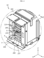
- FIG. 1 is a diagram exemplarily showing the overall shape of a battery module 10 according to an embodiment of the present disclosure
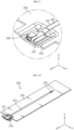
- FIG. 2 is a diagram showing a thermistor assembly 200 included in the battery module 10 of FIG. 1
- FIG. 3 is an exploded perspective view of the thermistor assembly 200 of FIG. 2
- FIG. 4 is an enlarged view showing a part of the battery module 10 of FIG. 1 in detail
- FIG. 5 is a cross-sectional view in the direction A-A' of FIG. 4 .
- FIG. 5 is a diagram showing the cross-section of the battery module 10 of FIG. 4 along the line A-A' with respect to the XZ plane).
- the X-axis direction shown in the drawing may mean the longitudinal direction of the battery cell 110 described later
- the Y-axis direction may mean the width direction of the battery cell 110 perpendicular to the X-axis direction and the horizontal plane (XY plane)
- Z-axis direction may mean the stacking direction of the battery cell 110 perpendicular to both the X-axis direction and the Y-axis direction.
- the battery module 10 may include a cell assembly 100 and a thermistor assembly 200.
- the cell assembly 100 may include a plurality of battery cells 110.
- each battery cell may mean a secondary battery.
- the battery cell 110 may be provided as a pouch-type battery cell, a cylindrical battery cell, or a prismatic battery cell.
- the battery cell 110 may be a pouch-type battery cell.
- the battery cells 110 may be arranged to be stacked in plurality in one direction and electrically connected to each other. That is, the plurality of battery cells 110 may be stacked in one direction to form a cell assembly 100.
- a bus bar frame F for sensing the voltage of the cell assembly 100 may be coupled to one side and the other side of the cell assembly 100 in the longitudinal direction.
- the bus bar frame F may support one side and the other side in the longitudinal direction of the cell assembly 100.
- the thermistor assembly 200 may be disposed inside the cell assembly 100.
- the thermistor assembly 200 may be disposed between the plurality of stacked battery cells 110.
- the thermistor assembly 200 may include a thermistor 210, a substrate 220, and a thermistor plate 230.
- the thermistor 210 may be configured to sense the temperature of the battery cell 110.
- the thermistor 210 may include an element whose resistance value varies according to temperature, and the temperature of the battery cell 110 may be sensed according to a change in the resistance value of the element.
- the thermistor 210 may be coupled to one side of the substrate 220 (e.g., a lower portion of the substrate 220).
- the substrate 220 may be configured to transmit temperature information of the battery cell 110 sensed by the thermistor 210 to the outside.
- the substrate 220 may be a flexible printed circuit board (FPCB).
- the thermistor 210 may be soldered to one side of the substrate 220. Accordingly, the thermistor 210 can be stably coupled to the substrate 220.
- the thermistor plate 230 may be disposed between the plurality of battery cells 110.
- the thermistor plate 230 may include a guide groove 231 in which the substrate 220 is disposed and the thermistor 210 is accommodated therein. In this way, the thermistor 210 may be accommodated inside the thermistor plate 230 through the guide groove 231.
- the thermistor 210 and the cell assembly 100 may not directly contact each other, and in particular, the load of the cell assembly 100 may be prevented from being directly transmitted to the thermistor 210.
- the thermistor plate 230 may be provided between the battery cells 110 in the stacking direction of the battery cells 110 so as to be disposed at an arbitrary position of the cell assembly 100.
- the thermistor plate 230 may be inserted between the battery cells 110 in the longitudinal direction of the battery cells 110 at an arbitrary position of the cell assembly 100 in the stacking direction of the battery cells 110. At this time, the thermistor plate 230 may be inserted between the battery cells 110 in the longitudinal direction of the battery cells 110 through a hole G formed in one side of the bus bar frame F.
- the thermistor plate 230 may be provided between the battery cells 110 such that the thermistor 210 is located at an arbitrary position of the cell assembly 100 with respect to the stacking direction of the battery cells 110 whose temperature is to be measured.
- the thermistor 210 may be provided at an arbitrary position of the cell assembly 100 on the thermistor plate 230.
- the thermistor 210 may sense the temperature of the battery cell 110 at an arbitrary position of the cell assembly 100.
- the thermistor plate 230 may be provided between battery cells 110 disposed at the center in the stacking direction of the battery cells 110 so as to be located at the center of the cell assembly 100.
- the thermistor 210 may be provided at a position corresponding to the center of the cell assembly 100 on the thermistor plate 230.
- the thermistor 210 may detect the temperature of the central portion of the cell assembly 100, which is the point with highest temperature within the battery module 10.
- FIG. 6 is an enlarged view of part B of FIG. 5
- FIG. 7 is a diagram showing a state in which a case body 1162 of the battery cell 110 of FIG. 5 and the thermistor plate 230 are in close contact.
- the thermistor plate 230 may be placed in close contact with the battery cells 110 facing each other in the stacking direction of the battery cells 110.
- the upper surface M1 and the lower surface M2 of the thermistor plate 230 may come into close contact with the battery cells 110 facing each other.
- the thermistor 210 provided inside the thermistor plate 230 can be positioned adjacent to the battery cells 110, so that the temperature of the battery cells 110 can be sensed more easily.
- the plurality of battery cells 110 may include an electrode assembly 112, an electrode lead 114, and a cell case 116, respectively.
- the electrode assembly 112 may include a first electrode plate having a first polarity, a second electrode plate having a second polarity, and a separator interposed between the first electrode plate and the second electrode plate.
- the first electrode plate may be a positive electrode plate or a negative electrode plate
- the second electrode plate may correspond to an electrode plate having a polarity opposite to that of the first electrode plate.
- the electrode lead 114 may be electrically connected to the electrode assembly 112.
- the electrode lead 114 may be formed on both sides of the longitudinal direction of the battery cell 110.
- the electrode lead 114 may be connected to a bus bar (not shown) provided to the bus bar frame F.
- the cell case 116 has an accommodation space for accommodating the electrode assembly 112, and may include a case body 1162 and a case terrace 1164.
- the electrode lead 114 may protrude a predetermined length out of the cell case 116.
- the case body 1162 may have an accommodation space accommodating the electrode assembly 112.
- the case terrace 1164 extends from the case body 1162 and may protrude the electrode lead 114 to the outside.
- the case terrace 1164 may be sealed to seal the accommodation space.
- the thermistor plate 230 described above may be in close contact with the case bodies 1162 of the battery cells 110 facing each other.
- the thermistor 210 provided inside the thermistor plate 230 can be positioned adjacent to the case body 1162 in which the electrode assembly 112 is accommodated, so that the temperature of the battery cell 110 can be sensed more easily.
- the thermistor plate 230 may be formed longer than the case body 1162 in the longitudinal direction of the battery cell 110.
- a uniform load may be transmitted to the thermistor plate 230 in the stacking direction of the battery cells 110. That is, local stress concentration on the thermistor plate 230 can be prevented. Also, the thermistor 210 may be more stably accommodated in the thermistor plate 230.
- FIG. 8 is an enlarged view of part H of FIG. 2 . At this time, the illustration of the substrate 220 described above and the bonding member 250 described later will be omitted in FIG. 8 .
- the guide groove 231 may be formed to correspond to the shape of the substrate 220 on the thermistor plate 230.
- the guide groove 231 may be provided to extend along the longitudinal direction of the battery cell 110.
- the guide groove 231 may guide stable arrangement of the substrate 220 with respect to the thermistor plate 230.
- the guide groove 231 may be formed on the thermistor plate 230 by indenting to a predetermined depth with respect to the stacking direction of the battery cells 110. Accordingly, in a state where the substrate 220 is disposed on the guide groove 231, the other side of the substrate 220 (e.g., the upper portion of the substrate 220) and the upper end of the guide groove 231 may be located on the same horizontal plane.
- stress concentration on the thermistor 210 coupled to one side of the substrate 220 can be prevented when the cell assembly 100 is compressed. Also, according to this embodiment, stress can be distributed over the entire thermistor plate 230, and damage to the battery cell 110 in contact with the thermistor plate 230 can also be prevented.
- the thermistor plate 230 may further include an accommodation groove 233.
- the accommodation groove 233 may be formed by indenting to a predetermined depth from the guide groove 231 with respect to the stacking direction of the battery cells 110. At this time, the thermistor 210 may be accommodated in the accommodation groove 233.
- the thermistor 210 may be more stably positioned inside the thermistor plate 230.
- the depth (d) of the accommodation groove 233 in the stacking direction of the battery cells 110 may be longer than the length (h) of the thermistor 210 in the stacking direction of the battery cells 110.
- the thermistor 210 may be disposed within the accommodation groove 233 to be spaced apart from an inner lower end of the accommodation groove 233 by a predetermined interval. That is, the thermistor 210 may be spaced apart from the inner lower end of the accommodation groove 233 by a predetermined distance with respect to the stacking direction of the battery cells 110 while being coupled to one side of the substrate 220.
- the distance between the inner lower end of the accommodation groove 233 and the thermistor 210 may be the difference between the depth (d) of the accommodation groove 233 in the stacking direction of the battery cells 110 and the length (h) of the thermistor 210 in the stacking direction of the battery cells 110.
- the thermistor 210 may not directly contact the inner lower end of the accommodation groove 233 with respect to the stacking direction of the battery cells 110. Accordingly, transfer of stress to the thermistor 210 during compression of the cell assembly 100 may be minimized.
- a formation position of the accommodation groove 233 on the thermistor plate 230 may be arbitrarily changed.
- the accommodation groove 233 may be formed on the thermistor plate 230 such that the thermistor 210 is located at an arbitrary position of the cell assembly 100 whose temperature is to be measured.
- the thermistor plate 230 may be provided between the battery cells 110 in the stacking direction of the battery cells 110 so as to be disposed at an arbitrary position of the cell assembly 100.
- the thermistor 210 may sense the temperature of the battery cell 110 at an arbitrary position of the cell assembly 100.
- the accommodation groove 233 may be formed on the thermistor plate 230 at a position corresponding to the center of the cell assembly 100. That is, the accommodation groove 233 may be formed on the thermistor plate 230 at a position corresponding to the center of the cell assembly 100 in both the longitudinal and width directions of the battery cell 110.
- the thermistor plate 230 may be provided between the battery cells 110 disposed at the center in the stacking direction of the battery cells 110 so as to be located at the center of the cell assembly 100.
- the thermistor 210 may detect the temperature of the central portion of the cell assembly 100, which is the point with highest temperature within the battery module 10.
- edges of the guide groove 231 and the accommodation groove 233 on a horizontal plane may be formed in a streamlined shape. Accordingly, when the cell assembly 100 is compressed, stress may be prevented from being locally concentrated on the thermistor plate 230. In addition, damage to the battery cell 110 in contact with the thermistor plate 230 can also be suppressed.
- the thermistor assembly 200 may further include an elastic pad 240 and a bonding member 250.
- the above-described substrate 220 may be configured to come into close contact with the battery cell 110 while being disposed on the guide groove 231. Accordingly, the thermistor 210 coupled to one side of the substrate 220 is also positioned as close to the battery cell 110 as possible, so that temperature measurement accuracy can be improved.
- the substrate 220 can come into close contact with the battery cell 110 by an elastic pad 240 described later.
- the elastic pad 240 is provided in the accommodation groove 233 and may be spaced apart from both sides of the thermistor 210 with respect to the longitudinal direction of the battery cell 110 on a horizontal plane.
- the elastic pad 240 may be spaced apart from the thermistor 210 to prevent direct contact with the thermistor 210.
- the elastic pad 240 may be coupled to one side of the substrate 220 (e.g., a lower portion of the substrate 220) with respect to the stacking direction of the battery cells 110.
- the elastic pad 240 may be configured to elastically support the substrate 220 toward a facing battery cell 110 with respect to the stacking direction of the battery cells 110.
- the substrate 220 to which the thermistor 210 is coupled can be always in close contact with the battery cells 110 due to the elastic restoring force of the elastic pad 240.
- the elastic pad 240 may be provided longer than the depth (d) of the accommodation groove 233 in the stacking direction of the battery cells 110.
- the length of the elastic pad 240 in the stacking direction of the battery cells 110 may be greater than the depth (d) of the accommodation groove 233 in the stacking direction of the battery cells 110 by about 20%, but is not limited thereto.
- the elastic pad 240 may be coupled to one side of the substrate 220 in the stacking direction of the battery cells 110, and the substrate 220 may be coupled to the guide groove 231 of the thermistor plate 230 in the stacking direction of the battery cells 110.
- the elastic pad 240 may be in a compressed state with respect to the stacking direction of the battery cells 110 between the substrate 220 and the inner lower end of the accommodation groove 233.
- the elastic pad 240 As the elastic pad 240 is compressed in the state of FIGS. 6 and 8 , elastic energy may be stored in the elastic pad 240. Accordingly, the elastic pad 240 may elastically support the substrate 220 toward the facing battery cell 110 in the stacking direction of the battery cells 110.
- the substrate 220 to which the thermistor 210 is coupled can be always in close contact with the battery cell 110 due to the elastic restoring force of the elastic pad 240. Accordingly, accuracy of temperature measurement by the thermistor 210 and thus accuracy of battery temperature monitoring may be maximized.
- the bonding member 250 may couple the substrate 220 to the guide groove 231. Also, the bonding member 250 may couple the elastic pad 240 to the substrate 220. As an example, the bonding member 250 may be a double-sided tape, but is not limited thereto.
- FIG. 9 is an enlarged view of part L of FIG. 2 .
- the thermistor assembly 200 may further include a connector 260.
- the connector 260 may be provided at one end of the substrate 220 in the longitudinal direction of the battery cell 110.
- the connector 260 may be connected to a separate connection line (not shown) and connected to a control device (e.g., BMS) outside the battery module 10.
- the substrate 220 may transmit temperature information of the battery cell 110 detected by the thermistor 210 to the external control device through the connector 260.
- the thermistor plate 230 may further include a connector disposing portion 235 and a connector fixing portion 237.
- the connector disposing portion 235 may be formed at one end of the thermistor plate 230 in the longitudinal direction of the battery cell 110. Accordingly, the connector 260 can be easily connected to the external control device.
- the connector fixing portion 237 may be coupled to the connector disposing portion 235 with respect to the stacking direction of the battery cells 110.
- the connector 260 may be fixed to the connector fixing portion 237. Accordingly, the connector 260 can be stably fixed to the thermistor plate 230.
- the connector 260, the connector disposing portion 235 and the connector fixing portion 237 may be located near the aforementioned hole G of the bus bar frame F.
- FIG. 10 is a diagram showing a thermistor assembly 202 according to another embodiment of the present disclosure. At this time, the illustration of the thermistor 210, the substrate 220, the elastic pad 240, the bonding member 250, and the connector 260 described above will be omitted in FIG. 10 .
- thermistor assembly 202 is similar to the thermistor assembly 200 of the previous embodiment, redundant description of components substantially the same as or similar to those of the previous embodiment will be omitted, and the following will focus on differences from the previous embodiment.
- the thermistor assembly 202 includes a thermistor plate 230 having a guide groove 231 and an accommodation groove 234.
- the accommodation groove 234 may be formed at an arbitrary position on the thermistor plate 230.
- the accommodation groove 234 may be formed on the thermistor plate 230 at a position that does not correspond to the center of the cell assembly 100.
- the thermistor 210 may sense the temperature of the battery cell 110 at an arbitrary position of the cell assembly 100.
- temperature measurement can be done freely at an arbitrary position of the cell assembly 100 according to the arrangement position of the thermistor plate 230 with respect to the cell assembly 100 and the arrangement position of the thermistor 210 in the thermistor plate 230.
- the temperature of the central portion of the cell assembly 100 which is a point with highest temperature inside the battery module 10 can be sensed according to the arrangement position of the thermistor plate 230 with respect to the cell assembly 100 and the arrangement position of the thermistor 210 in the thermistor plate 230. Accordingly, the battery module 10 can be more safely and efficiently managed.
- the thermistor assemblies 200 and 202 of the present disclosure damage to the thermistor 210 and the battery cell 110 can be prevented even when the thermistor assemblies 200 and 202 are placed between the battery cells 110, and also accuracy of battery temperature monitoring can be improved by allowing the substrate 220 equipped with the thermistor 210 to be always in close contact with the battery cell 110.
- the battery module 10 described above may further include a module case 300.
- the module case 300 may accommodate the battery module 10 therein. To this end, an accommodation space for accommodating the battery module 10 may be provided in the module case 300.
- At least one battery module 10 may be provided as an energy source to configure a battery pack.
- the battery pack according to the present disclosure may further include, in addition to the battery module 10, various devices for controlling the charging and discharging of the cell assembly 100, such as a battery management system (BMS), a current sensor, and a fuse.
- BMS battery management system
- a current sensor current sensor
- a fuse fuse
- At least one battery pack according to the present disclosure may be provided as an energy source to configure an energy storage system (ESS).
- ESS energy storage system
Landscapes
- Electrochemistry (AREA)
- General Chemical & Material Sciences (AREA)
- Chemical & Material Sciences (AREA)
- Chemical Kinetics & Catalysis (AREA)
- Physics & Mathematics (AREA)
- General Physics & Mathematics (AREA)
- Engineering & Computer Science (AREA)
- Manufacturing & Machinery (AREA)
- Nonlinear Science (AREA)
- Microelectronics & Electronic Packaging (AREA)
- Battery Mounting, Suspending (AREA)
- Secondary Cells (AREA)
- Connection Of Batteries Or Terminals (AREA)
Abstract
Description
- The present disclosure relates to a battery module, a battery pack, and an energy storage system, and more particularly, to a battery module, a battery pack, and an energy storage system that can be safely and efficiently managed. The present application claims priority to
Korean Patent Application No. 10-2022-0030829 filed on March 11, 2022 - Currently commercialized secondary batteries include nickel cadmium batteries, nickel hydride batteries, nickel zinc batteries, and lithium secondary batteries. Among them, lithium secondary batteries are in the spotlight because they have almost no memory effect compared to nickel-based batteries, and thus have advantages of free charge/discharge, very low self-discharge rate, and high energy density.
- Recently, secondary batteries have been widely used not only for small devices such as portable electronic devices, but also for medium and large devices such as electric vehicles and energy storage systems (ESSs). For example, when used in an electric vehicle or energy storage system, a cell assembly in which a large number of secondary batteries are connected in series and/or in parallel may be configured to increase energy capacity and output. In addition, a battery pack is formed by connecting a plurality of these cell assemblies.
- On the other hand, in order to use the battery pack safely and efficiently, it is necessary to accurately detect the charge/discharge voltage state and temperature of secondary batteries. To this end, the battery pack may include a voltage sensing device for detecting voltage of secondary batteries and a temperature sensor for detecting temperature of secondary batteries. The voltage sensing device and temperature sensors can be installed inside the cell housing along with the secondary batteries.
- In addition, the battery pack may further include various electric components for controlling the charging and discharging of the secondary batteries, such as a BMS, a relay, a current sensor, and a fuse. The various electrical components can be housed integrally in the electric component housing separately from the secondary batteries.
- There may be several methods for monitoring the temperature of the battery pack. As an example, a method using a thermistor is widely used. In the case of a method using such a thermistor, the thermistor may be provided at a predetermined location inside the battery pack. In addition, a control device connected to the thermistor, such as a battery monitoring system (BMS), may monitor the temperature of the battery cell through a signal transmitted from the thermistor.
- As an example, the thermistor may include an element whose resistance value varies according to temperature, such as NTC (Negative Temperature Coefficient). Accordingly, a voltage value input to the control device may vary due to a change in resistance value according to the temperature of the NTC. In addition, the control device may judge the temperature of the battery cell sensed by the thermistor according to the input voltage value using a reference table or the like stored in advance.
- Meanwhile, in the case of a conventional battery pack, the temperature of a battery cell is measured by covering the thermistor with a battery pack housing, or the temperature of the battery cell is measured by providing a thermistor to a bus bar frame.
- In the case of such a conventional battery pack, it is difficult to measure the temperature of the central portion of the cell assembly in which a plurality of battery cells are stacked, and it is difficult to measure the temperature regardless of the position of the battery cells. In addition, there is a problem in that the battery cell and the thermistor are locally damaged when swelling of the battery cell occurs.
- The present disclosure is designed to solve the problems of the related art, and therefore the present disclosure is directed to providing a battery module, a battery pack, and an energy storage system that can be safely and efficiently managed.
- However, the technical problem to be solved by the present disclosure is not limited to the above-mentioned problems, and other problems not mentioned will be clearly understood by those skilled in the art from the description below.
- In one aspect of the present disclosure, there is provided a battery module, comprising: a cell assembly having a plurality of stacked battery cells; a thermistor configured to sense the temperature of the battery cell; a substrate having one side to which the thermistor is coupled and configured to transmit temperature information of the battery cell sensed by the thermistor to the outside; and a thermistor plate on which the substrate is disposed and a guide groove in which the thermistor is accommodated is formed, the thermistor plate being disposed between the plurality of battery cells.
- Preferably, the thermistor plate may be provided between battery cells disposed at a center in a stacking direction of the battery cells so as to be located at a center of the cell assembly.
- Preferably, the thermistor plate may be placed in close contact with the battery cells facing each other in a stacking direction of the battery cells.
- Preferably, each of the plurality of battery cells may include an electrode assembly; an electrode lead electrically connected to the electrode assembly; and a cell case including a case body having an accommodation space accommodating the electrode assembly, and a case terrace extending from the case body and protruding the electrode lead to the outside, and the thermistor plate may be in close contact with the case bodies of the facing battery cells.
- Preferably, the thermistor plate may be formed longer than the case body in a longitudinal direction of the battery cell.
- Preferably, the guide groove may be formed on the thermistor plate to correspond to the shape of the substrate and extends along a longitudinal direction of the battery cell.
- Preferably, the guide groove may be formed on the thermistor plate by indenting to a predetermined depth with respect to the stacking direction of the battery cells, and in a state where the substrate is placed in the guide groove, the other side of the substrate and an upper end of the guide groove may be located on the same horizontal plane.
- Preferably, the thermistor plate may further include an accommodation groove formed by indenting to a predetermined depth from the guide groove with respect to a stacking direction of the battery cells, so that the thermistor is accommodated therein.
- Preferably, the thermistor may be disposed at a predetermined distance from an inner lower end of the accommodation groove within the accommodation groove.
- Preferably, the accommodation groove may be formed on the thermistor plate at a position corresponding to the center of the cell assembly.
- Preferably, the substrate may be configured to be in close contact with the battery cell while being placed in the guide groove.
- Preferably, the battery module may further comprise an elastic pad provided in the accommodation groove and configured to elastically support the substrate toward a facing battery cell with respect to the stacking direction of the battery cells.
- Preferably, the elastic pad may be provided longer than the depth of the accommodation groove in the stacking direction.
- In addition, a battery pack according to an embodiment of the present disclosure comprises at least one battery module according to an embodiment of the present disclosure as described above.
- In addition, an energy storage system according to an embodiment of the present disclosure comprises at least one battery pack according to an embodiment of the present disclosure as described above.
- According to the embodiment of the present disclosure, temperature measurement can be freely performed at an arbitrary position of the cell assembly according to the arrangement position of the thermistor plate with respect to the cell assembly and the arrangement position of the thermistor on the thermistor plate.
- In addition, according to the embodiment of the present disclosure, the temperature of the central portion of the cell assembly, which is the highest temperature point inside the battery module, can be sensed according to the arrangement position of the thermistor plate with respect to the cell assembly and the arrangement position of the thermistor on the thermistor plate. Accordingly, the battery module can be more safely and efficiently managed.
- In addition, through the structure of the thermistor assembly of the present disclosure, damage to the thermistor and battery cells can be prevented even when the thermistor assembly is placed between battery cells, and the substrate equipped with the thermistor is always in close contact with the battery cells, so that the accuracy of battery temperature monitoring can be improved.
- In addition, various additional effects may be achieved by various embodiments of the present disclosure. Various effects of the present disclosure will be described in detail in each embodiment, or descriptions of effects that can be easily understood by those skilled in the art will be omitted.
- The accompanying drawings illustrate a preferred embodiment of the present disclosure and together with the foregoing disclosure, serve to provide further understanding of the technical features of the present disclosure, and thus, the present disclosure is not construed as being limited to the drawing.
-
FIG. 1 is a diagram exemplarily showing the overall shape of a battery module according to an embodiment of the present disclosure. -
FIG. 2 is a diagram showing a thermistor assembly included in the battery module ofFIG. 1 . -
FIG. 3 is an exploded perspective view of the thermistor assembly ofFIG. 2 . -
FIG. 4 is an enlarged view showing a part of the battery module ofFIG. 1 in detail. -
FIG. 5 is a cross-sectional view in the direction A-A' ofFIG. 4 . -
FIG. 6 is an enlarged view of part B ofFIG. 5 . -
FIG. 7 is a diagram showing a state in which a case body of the battery cell ofFIG. 5 and the thermistor plate are in close contact. -
FIG. 8 is an enlarged view of part H ofFIG. 2 . -
FIG. 9 is an enlarged view of part L ofFIG. 2 . -
FIG. 10 is a diagram showing a thermistor assembly according to another embodiment of the present disclosure. - Hereinafter, preferred embodiments of the present disclosure will be described in detail with reference to the accompanying drawings. Prior to the description, it should be understood that the terms used in the specification and the appended claims should not be construed as limited to general and dictionary meanings, but interpreted based on the meanings and concepts corresponding to technical aspects of the present disclosure on the basis of the principle that the inventor is allowed to define terms appropriately for the best explanation.
- Therefore, the description proposed herein is just a preferable example for the purpose of illustrations only, not intended to limit the scope of the disclosure, so it should be understood that other equivalents and modifications could be made thereto without departing from the scope of the disclosure.
-
FIG. 1 is a diagram exemplarily showing the overall shape of abattery module 10 according to an embodiment of the present disclosure,FIG. 2 is a diagram showing athermistor assembly 200 included in thebattery module 10 ofFIG. 1 ,FIG. 3 is an exploded perspective view of thethermistor assembly 200 ofFIG. 2 ,FIG. 4 is an enlarged view showing a part of thebattery module 10 ofFIG. 1 in detail, andFIG. 5 is a cross-sectional view in the direction A-A' ofFIG. 4 . (In detail,FIG. 5 is a diagram showing the cross-section of thebattery module 10 ofFIG. 4 along the line A-A' with respect to the XZ plane). - In the embodiment of the present disclosure, the X-axis direction shown in the drawing may mean the longitudinal direction of the
battery cell 110 described later, the Y-axis direction may mean the width direction of thebattery cell 110 perpendicular to the X-axis direction and the horizontal plane (XY plane), and Z-axis direction may mean the stacking direction of thebattery cell 110 perpendicular to both the X-axis direction and the Y-axis direction. - Referring to
FIGS. 1 to 5 , thebattery module 10 may include acell assembly 100 and athermistor assembly 200. - The
cell assembly 100 may include a plurality ofbattery cells 110. Here, each battery cell may mean a secondary battery. Thebattery cell 110 may be provided as a pouch-type battery cell, a cylindrical battery cell, or a prismatic battery cell. As an example, thebattery cell 110 may be a pouch-type battery cell. - The
battery cells 110 may be arranged to be stacked in plurality in one direction and electrically connected to each other. That is, the plurality ofbattery cells 110 may be stacked in one direction to form acell assembly 100. - A bus bar frame F for sensing the voltage of the
cell assembly 100 may be coupled to one side and the other side of thecell assembly 100 in the longitudinal direction. The bus bar frame F may support one side and the other side in the longitudinal direction of thecell assembly 100. - The
thermistor assembly 200 may be disposed inside thecell assembly 100. In particular, thethermistor assembly 200 may be disposed between the plurality of stackedbattery cells 110. - The
thermistor assembly 200 may include athermistor 210, asubstrate 220, and athermistor plate 230. - The
thermistor 210 may be configured to sense the temperature of thebattery cell 110. As an example, thethermistor 210 may include an element whose resistance value varies according to temperature, and the temperature of thebattery cell 110 may be sensed according to a change in the resistance value of the element. - The
thermistor 210 may be coupled to one side of the substrate 220 (e.g., a lower portion of the substrate 220). In addition, thesubstrate 220 may be configured to transmit temperature information of thebattery cell 110 sensed by thethermistor 210 to the outside. As an example, thesubstrate 220 may be a flexible printed circuit board (FPCB). - In the embodiment of the present disclosure, the
thermistor 210 may be soldered to one side of thesubstrate 220. Accordingly, thethermistor 210 can be stably coupled to thesubstrate 220. - The
thermistor plate 230 may be disposed between the plurality ofbattery cells 110. Thethermistor plate 230 may include aguide groove 231 in which thesubstrate 220 is disposed and thethermistor 210 is accommodated therein. In this way, thethermistor 210 may be accommodated inside thethermistor plate 230 through theguide groove 231. - Accordingly, the
thermistor 210 and thecell assembly 100 may not directly contact each other, and in particular, the load of thecell assembly 100 may be prevented from being directly transmitted to thethermistor 210. - In particular, the
thermistor plate 230 may be provided between thebattery cells 110 in the stacking direction of thebattery cells 110 so as to be disposed at an arbitrary position of thecell assembly 100. - The
thermistor plate 230 may be inserted between thebattery cells 110 in the longitudinal direction of thebattery cells 110 at an arbitrary position of thecell assembly 100 in the stacking direction of thebattery cells 110. At this time, thethermistor plate 230 may be inserted between thebattery cells 110 in the longitudinal direction of thebattery cells 110 through a hole G formed in one side of the bus bar frame F. - That is, the
thermistor plate 230 may be provided between thebattery cells 110 such that thethermistor 210 is located at an arbitrary position of thecell assembly 100 with respect to the stacking direction of thebattery cells 110 whose temperature is to be measured. - Also, the
thermistor 210 may be provided at an arbitrary position of thecell assembly 100 on thethermistor plate 230. - Accordingly, the
thermistor 210 may sense the temperature of thebattery cell 110 at an arbitrary position of thecell assembly 100. - In one embodiment, the
thermistor plate 230 may be provided betweenbattery cells 110 disposed at the center in the stacking direction of thebattery cells 110 so as to be located at the center of thecell assembly 100. - In this case, the
thermistor 210 may be provided at a position corresponding to the center of thecell assembly 100 on thethermistor plate 230. - In this case, the
thermistor 210 may detect the temperature of the central portion of thecell assembly 100, which is the point with highest temperature within thebattery module 10. -
FIG. 6 is an enlarged view of part B ofFIG. 5 , andFIG. 7 is a diagram showing a state in which acase body 1162 of thebattery cell 110 ofFIG. 5 and thethermistor plate 230 are in close contact. - Referring to
FIGS. 1 to 7 , thethermistor plate 230 may be placed in close contact with thebattery cells 110 facing each other in the stacking direction of thebattery cells 110. As an example, the upper surface M1 and the lower surface M2 of thethermistor plate 230 may come into close contact with thebattery cells 110 facing each other. - According to this embodiment of the present disclosure, the
thermistor 210 provided inside thethermistor plate 230 can be positioned adjacent to thebattery cells 110, so that the temperature of thebattery cells 110 can be sensed more easily. - Hereinafter, the aforementioned embodiment will be described in more detail.
- Specifically, the plurality of
battery cells 110 may include anelectrode assembly 112, anelectrode lead 114, and a cell case 116, respectively. - The
electrode assembly 112 may include a first electrode plate having a first polarity, a second electrode plate having a second polarity, and a separator interposed between the first electrode plate and the second electrode plate. As an example, the first electrode plate may be a positive electrode plate or a negative electrode plate, and the second electrode plate may correspond to an electrode plate having a polarity opposite to that of the first electrode plate. - The
electrode lead 114 may be electrically connected to theelectrode assembly 112. Theelectrode lead 114 may be formed on both sides of the longitudinal direction of thebattery cell 110. In addition, theelectrode lead 114 may be connected to a bus bar (not shown) provided to the bus bar frame F. - The cell case 116 has an accommodation space for accommodating the
electrode assembly 112, and may include acase body 1162 and acase terrace 1164. In addition, theelectrode lead 114 may protrude a predetermined length out of the cell case 116. - The
case body 1162 may have an accommodation space accommodating theelectrode assembly 112. - The
case terrace 1164 extends from thecase body 1162 and may protrude theelectrode lead 114 to the outside. Thecase terrace 1164 may be sealed to seal the accommodation space. - In the embodiment of the present disclosure, the
thermistor plate 230 described above may be in close contact with thecase bodies 1162 of thebattery cells 110 facing each other. - According to this embodiment, the
thermistor 210 provided inside thethermistor plate 230 can be positioned adjacent to thecase body 1162 in which theelectrode assembly 112 is accommodated, so that the temperature of thebattery cell 110 can be sensed more easily. - In particular, the
thermistor plate 230 may be formed longer than thecase body 1162 in the longitudinal direction of thebattery cell 110. - According to this embodiment of the present disclosure, in a state where the
cell assembly 100 is compressed with respect to the stacking direction of thebattery cells 110, a uniform load may be transmitted to thethermistor plate 230 in the stacking direction of thebattery cells 110. That is, local stress concentration on thethermistor plate 230 can be prevented. Also, thethermistor 210 may be more stably accommodated in thethermistor plate 230. - Hereinafter, the above-described
thermistor assembly 200 will be described in more detail. -
FIG. 8 is an enlarged view of part H ofFIG. 2 . At this time, the illustration of thesubstrate 220 described above and thebonding member 250 described later will be omitted inFIG. 8 . - Referring to
FIGS. 2 to 8 , theguide groove 231 may be formed to correspond to the shape of thesubstrate 220 on thethermistor plate 230. - In addition, the
guide groove 231 may be provided to extend along the longitudinal direction of thebattery cell 110. - Accordingly, the
guide groove 231 may guide stable arrangement of thesubstrate 220 with respect to thethermistor plate 230. - In particular, the
guide groove 231 may be formed on thethermistor plate 230 by indenting to a predetermined depth with respect to the stacking direction of thebattery cells 110. Accordingly, in a state where thesubstrate 220 is disposed on theguide groove 231, the other side of the substrate 220 (e.g., the upper portion of the substrate 220) and the upper end of theguide groove 231 may be located on the same horizontal plane. - According to this embodiment of the present disclosure, stress concentration on the
thermistor 210 coupled to one side of thesubstrate 220 can be prevented when thecell assembly 100 is compressed. Also, according to this embodiment, stress can be distributed over theentire thermistor plate 230, and damage to thebattery cell 110 in contact with thethermistor plate 230 can also be prevented. - Referring back to
FIGS. 2 to 8 , thethermistor plate 230 may further include anaccommodation groove 233. - The
accommodation groove 233 may be formed by indenting to a predetermined depth from theguide groove 231 with respect to the stacking direction of thebattery cells 110. At this time, thethermistor 210 may be accommodated in theaccommodation groove 233. - Accordingly, the
thermistor 210 may be more stably positioned inside thethermistor plate 230. - Referring to
FIG. 6 , the depth (d) of theaccommodation groove 233 in the stacking direction of thebattery cells 110 may be longer than the length (h) of thethermistor 210 in the stacking direction of thebattery cells 110. - In addition, the
thermistor 210 may be disposed within theaccommodation groove 233 to be spaced apart from an inner lower end of theaccommodation groove 233 by a predetermined interval. That is, thethermistor 210 may be spaced apart from the inner lower end of theaccommodation groove 233 by a predetermined distance with respect to the stacking direction of thebattery cells 110 while being coupled to one side of thesubstrate 220. - At this time, the distance between the inner lower end of the
accommodation groove 233 and thethermistor 210 may be the difference between the depth (d) of theaccommodation groove 233 in the stacking direction of thebattery cells 110 and the length (h) of thethermistor 210 in the stacking direction of thebattery cells 110. - Accordingly, the
thermistor 210 may not directly contact the inner lower end of theaccommodation groove 233 with respect to the stacking direction of thebattery cells 110. Accordingly, transfer of stress to thethermistor 210 during compression of thecell assembly 100 may be minimized. - In the embodiment of the present disclosure, a formation position of the
accommodation groove 233 on thethermistor plate 230 may be arbitrarily changed. - That is, the
accommodation groove 233 may be formed on thethermistor plate 230 such that thethermistor 210 is located at an arbitrary position of thecell assembly 100 whose temperature is to be measured. - Also, as described above, the
thermistor plate 230 may be provided between thebattery cells 110 in the stacking direction of thebattery cells 110 so as to be disposed at an arbitrary position of thecell assembly 100. - Accordingly, the
thermistor 210 may sense the temperature of thebattery cell 110 at an arbitrary position of thecell assembly 100. - In one embodiment, as shown in
FIGS. 2 and3 , theaccommodation groove 233 may be formed on thethermistor plate 230 at a position corresponding to the center of thecell assembly 100. That is, theaccommodation groove 233 may be formed on thethermistor plate 230 at a position corresponding to the center of thecell assembly 100 in both the longitudinal and width directions of thebattery cell 110. - Also, as described above, the
thermistor plate 230 may be provided between thebattery cells 110 disposed at the center in the stacking direction of thebattery cells 110 so as to be located at the center of thecell assembly 100. - In this case, the
thermistor 210 may detect the temperature of the central portion of thecell assembly 100, which is the point with highest temperature within thebattery module 10. - Meanwhile, although not shown in detail, edges of the
guide groove 231 and theaccommodation groove 233 on a horizontal plane may be formed in a streamlined shape. Accordingly, when thecell assembly 100 is compressed, stress may be prevented from being locally concentrated on thethermistor plate 230. In addition, damage to thebattery cell 110 in contact with thethermistor plate 230 can also be suppressed. - Referring back to
FIGS. 2 to 8 , thethermistor assembly 200 may further include anelastic pad 240 and abonding member 250. - The above-described
substrate 220 may be configured to come into close contact with thebattery cell 110 while being disposed on theguide groove 231. Accordingly, thethermistor 210 coupled to one side of thesubstrate 220 is also positioned as close to thebattery cell 110 as possible, so that temperature measurement accuracy can be improved. - The
substrate 220 can come into close contact with thebattery cell 110 by anelastic pad 240 described later. - The
elastic pad 240 is provided in theaccommodation groove 233 and may be spaced apart from both sides of thethermistor 210 with respect to the longitudinal direction of thebattery cell 110 on a horizontal plane. Theelastic pad 240 may be spaced apart from thethermistor 210 to prevent direct contact with thethermistor 210. - Also, the
elastic pad 240 may be coupled to one side of the substrate 220 (e.g., a lower portion of the substrate 220) with respect to the stacking direction of thebattery cells 110. - In particular, the
elastic pad 240 may be configured to elastically support thesubstrate 220 toward a facingbattery cell 110 with respect to the stacking direction of thebattery cells 110. - According to this embodiment of the present disclosure, the
substrate 220 to which thethermistor 210 is coupled can be always in close contact with thebattery cells 110 due to the elastic restoring force of theelastic pad 240. - Hereinafter, the aforementioned embodiment will be described in more detail.
- Specifically, the
elastic pad 240 may be provided longer than the depth (d) of theaccommodation groove 233 in the stacking direction of thebattery cells 110. As an example, the length of theelastic pad 240 in the stacking direction of thebattery cells 110 may be greater than the depth (d) of theaccommodation groove 233 in the stacking direction of thebattery cells 110 by about 20%, but is not limited thereto. - In particular, the
elastic pad 240 may be coupled to one side of thesubstrate 220 in the stacking direction of thebattery cells 110, and thesubstrate 220 may be coupled to theguide groove 231 of thethermistor plate 230 in the stacking direction of thebattery cells 110. - In this way, since the length of the
elastic pad 240 in the stacking direction of thebattery cells 110 is greater than the depth (d) of theaccommodation groove 233 in the stacking direction of thebattery cells 110, in the state ofFIGS. 6 and8 , theelastic pad 240 may be in a compressed state with respect to the stacking direction of thebattery cells 110 between thesubstrate 220 and the inner lower end of theaccommodation groove 233. - As the
elastic pad 240 is compressed in the state ofFIGS. 6 and8 , elastic energy may be stored in theelastic pad 240. Accordingly, theelastic pad 240 may elastically support thesubstrate 220 toward the facingbattery cell 110 in the stacking direction of thebattery cells 110. - According to this embodiment of the present disclosure, the
substrate 220 to which thethermistor 210 is coupled can be always in close contact with thebattery cell 110 due to the elastic restoring force of theelastic pad 240. Accordingly, accuracy of temperature measurement by thethermistor 210 and thus accuracy of battery temperature monitoring may be maximized. - The
bonding member 250 may couple thesubstrate 220 to theguide groove 231. Also, thebonding member 250 may couple theelastic pad 240 to thesubstrate 220. As an example, thebonding member 250 may be a double-sided tape, but is not limited thereto. -
FIG. 9 is an enlarged view of part L ofFIG. 2 . - Referring to
FIGS. 2 to 9 , thethermistor assembly 200 may further include aconnector 260. - The
connector 260 may be provided at one end of thesubstrate 220 in the longitudinal direction of thebattery cell 110. As an example, theconnector 260 may be connected to a separate connection line (not shown) and connected to a control device (e.g., BMS) outside thebattery module 10. At this time, thesubstrate 220 may transmit temperature information of thebattery cell 110 detected by thethermistor 210 to the external control device through theconnector 260. - Referring to
FIGS. 2 to 9 , thethermistor plate 230 may further include aconnector disposing portion 235 and aconnector fixing portion 237. - The
connector disposing portion 235 may be formed at one end of thethermistor plate 230 in the longitudinal direction of thebattery cell 110. Accordingly, theconnector 260 can be easily connected to the external control device. - Also, the
connector fixing portion 237 may be coupled to theconnector disposing portion 235 with respect to the stacking direction of thebattery cells 110. Theconnector 260 may be fixed to theconnector fixing portion 237. Accordingly, theconnector 260 can be stably fixed to thethermistor plate 230. - In one embodiment, as shown in
FIGS. 4 and5 , theconnector 260, theconnector disposing portion 235 and theconnector fixing portion 237 may be located near the aforementioned hole G of the bus bar frame F. -
FIG. 10 is a diagram showing athermistor assembly 202 according to another embodiment of the present disclosure. At this time, the illustration of thethermistor 210, thesubstrate 220, theelastic pad 240, thebonding member 250, and theconnector 260 described above will be omitted inFIG. 10 . - Since the
thermistor assembly 202 according to this embodiment is similar to thethermistor assembly 200 of the previous embodiment, redundant description of components substantially the same as or similar to those of the previous embodiment will be omitted, and the following will focus on differences from the previous embodiment. - Referring to
FIG. 10 , thethermistor assembly 202 includes athermistor plate 230 having aguide groove 231 and anaccommodation groove 234. - The
accommodation groove 234 may be formed at an arbitrary position on thethermistor plate 230. For example, theaccommodation groove 234 may be formed on thethermistor plate 230 at a position that does not correspond to the center of thecell assembly 100. - In this way, the position where the
accommodation groove 234 is formed on thethermistor plate 230 can be freely changed. Accordingly, thethermistor 210 may sense the temperature of thebattery cell 110 at an arbitrary position of thecell assembly 100. - As described above, according to the embodiment of the present disclosure, temperature measurement can be done freely at an arbitrary position of the
cell assembly 100 according to the arrangement position of thethermistor plate 230 with respect to thecell assembly 100 and the arrangement position of thethermistor 210 in thethermistor plate 230. - In addition, according to the embodiment of the present disclosure, the temperature of the central portion of the
cell assembly 100, which is a point with highest temperature inside thebattery module 10, can be sensed according to the arrangement position of thethermistor plate 230 with respect to thecell assembly 100 and the arrangement position of thethermistor 210 in thethermistor plate 230. Accordingly, thebattery module 10 can be more safely and efficiently managed. - In addition, through the structures of the
thermistor assemblies thermistor 210 and thebattery cell 110 can be prevented even when thethermistor assemblies battery cells 110, and also accuracy of battery temperature monitoring can be improved by allowing thesubstrate 220 equipped with thethermistor 210 to be always in close contact with thebattery cell 110. - Referring again to
FIGS. 1 to 10 , thebattery module 10 described above may further include amodule case 300. - The
module case 300 may accommodate thebattery module 10 therein. To this end, an accommodation space for accommodating thebattery module 10 may be provided in themodule case 300. - In addition, at least one
battery module 10 according to the present disclosure may be provided as an energy source to configure a battery pack. - Meanwhile, the battery pack according to the present disclosure may further include, in addition to the
battery module 10, various devices for controlling the charging and discharging of thecell assembly 100, such as a battery management system (BMS), a current sensor, and a fuse. - In addition, at least one battery pack according to the present disclosure may be provided as an energy source to configure an energy storage system (ESS).
- The present disclosure has been described in detail. However, it should be understood that the detailed description and specific examples, while indicating preferred embodiments of the disclosure, are given by way of illustration only, since various changes and modifications within the scope of the disclosure will become apparent to those skilled in the art from this detailed description.
- On the other hand, in the present disclosure, terms indicating directions such as up, down, left, right, front, and back are used, but these terms are only for convenience of explanation, and it is obvious to those skilled in the art of the present disclosure that the terms may vary depending on the location of the target object or the location of the observer.
-
- 10 : battery module
- 100 : cell assembly
- 110 : battery cell
- 112 : electrode assembly
- 114 : electrode lead
- 116 : cell case
- 1162 : case body
- 1164 : case terrace
- 200, 202 : thermistor assembly
- 210 : thermistor
- 220 : substrate
- 230 : thermistor plate
- 231 : guide groove
- 233, 234 : accommodation groove
- 240 : elastic pad
- 250 : bonding member
- 260 : connector
- 300 : module case
Claims (15)
- A battery module, comprising:a cell assembly having a plurality of stacked battery cells;a thermistor configured to sense the temperature of the battery cell;a substrate having one side to which the thermistor is coupled and configured to transmit temperature information of the battery cell sensed by the thermistor to the outside; anda thermistor plate on which the substrate is disposed and a guide groove in which the thermistor is accommodated is formed, the thermistor plate being disposed between the plurality of battery cells.
- The battery module according to claim 1, wherein the thermistor plate is provided between battery cells disposed at a center in a stacking direction of the battery cells so as to be located at a center of the cell assembly.
- The battery module according to claim 1, wherein the thermistor plate is placed in close contact with the battery cells facing each other in a stacking direction of the battery cells.
- The battery module according to claim 3, wherein each of the plurality of battery cells includes:an electrode assembly;an electrode lead electrically connected to the electrode assembly; anda cell case including a case body having an accommodation space accommodating the electrode assembly, and a case terrace extending from the case body and protruding the electrode lead to the outside,wherein the thermistor plate is in close contact with the case bodies of the facing battery cells.
- The battery module according to claim 4, wherein the thermistor plate is formed longer than the case body in a longitudinal direction of the battery cell.
- The battery module according to claim 1, wherein the guide groove is formed on the thermistor plate to correspond to the shape of the substrate and extends along a longitudinal direction of the battery cell.
- The battery module according to claim 6, wherein the guide groove is formed on the thermistor plate by indenting to a predetermined depth with respect to the stacking direction of the battery cells, and
wherein in a state where the substrate is placed in the guide groove, the other side of the substrate and an upper end of the guide groove are located on the same horizontal plane. - The battery module according to claim 1, wherein the thermistor plate further includes an accommodation groove formed by indenting to a predetermined depth from the guide groove with respect to a stacking direction of the battery cells, so that the thermistor is accommodated therein.
- The battery module according to claim 8, wherein the thermistor is disposed at a predetermined distance from an inner lower end of the accommodation groove within the accommodation groove.
- The battery module according to claim 8, wherein the accommodation groove is formed on the thermistor plate at a position corresponding to the center of the cell assembly.
- The battery module according to claim 8, wherein the substrate is configured to be in close contact with the battery cell while being placed in the guide groove.
- The battery module according to claim 11, further comprising an elastic pad provided in the accommodation groove and configured to elastically support the substrate toward a facing battery cell with respect to the stacking direction of the battery cells.
- The battery module according to claim 12, wherein the elastic pad is provided longer than the depth of the accommodation groove in the stacking direction.
- A battery pack, comprising at least one battery module according to any one of claims 1 to 13.
- An energy storage system, comprising at least one battery pack according to claim 14.
Applications Claiming Priority (2)
| Application Number | Priority Date | Filing Date | Title |
|---|---|---|---|
| KR1020220030829A KR20230133620A (en) | 2022-03-11 | 2022-03-11 | Battery module, battery pack and energy storage system |
| PCT/KR2023/003335 WO2023172114A1 (en) | 2022-03-11 | 2023-03-10 | Battery module, battery pack, and energy storage system |
Publications (2)
| Publication Number | Publication Date |
|---|---|
| EP4475272A1 true EP4475272A1 (en) | 2024-12-11 |
| EP4475272A4 EP4475272A4 (en) | 2025-05-21 |
Family
ID=87919660
Family Applications (1)
| Application Number | Title | Priority Date | Filing Date |
|---|---|---|---|
| EP23767215.9A Pending EP4475272A4 (en) | 2022-03-11 | 2023-03-10 | BATTERY MODULE, BATTERY PACK AND ENERGY STORAGE SYSTEM |
Country Status (6)
| Country | Link |
|---|---|
| US (1) | US20260031418A1 (en) |
| EP (1) | EP4475272A4 (en) |
| JP (1) | JP7827880B2 (en) |
| KR (1) | KR20230133620A (en) |
| CN (2) | CN118476083A (en) |
| WO (1) | WO2023172114A1 (en) |
Family Cites Families (13)
| Publication number | Priority date | Publication date | Assignee | Title |
|---|---|---|---|---|
| JPH0727562Y2 (en) * | 1990-11-14 | 1995-06-21 | 三洋電機株式会社 | Battery pack |
| KR100801635B1 (en) * | 2004-11-02 | 2008-02-05 | 주식회사 엘지화학 | Member for measuring battery voltage and temperature of battery pack |
| EP2479835B1 (en) | 2009-09-15 | 2017-01-11 | LG Chem, Ltd. | Battery module having a temperature sensor installed thereon, and medium or large battery pack including same |
| KR101577387B1 (en) * | 2013-05-06 | 2015-12-16 | 주식회사 엘지화학 | Secondary battery, and secondary battery module and secondary battery pack comprising the same |
| DE102013222293A1 (en) | 2013-11-04 | 2015-05-07 | Robert Bosch Gmbh | battery module |
| DE102013021553A1 (en) * | 2013-12-18 | 2015-06-18 | Daimler Ag | High-voltage battery |
| WO2016051616A1 (en) | 2014-09-30 | 2016-04-07 | 三洋電機株式会社 | Battery pack |
| KR102411932B1 (en) * | 2015-05-15 | 2022-06-22 | 삼성에스디아이 주식회사 | Rechargeable battery |
| KR20170084789A (en) * | 2016-01-13 | 2017-07-21 | 주식회사 엘지화학 | Safety Member for Battery Cell and Battery Pack Comprising the Same |
| CN207441908U (en) * | 2017-12-08 | 2018-06-01 | 浙江衡远新能源科技有限公司 | A kind of soft bag lithium ionic cell for surveying internal temperature |
| KR102422889B1 (en) | 2020-09-03 | 2022-07-21 | 현대무벡스 주식회사 | Vertical transfer system |
| JP7425014B2 (en) | 2021-04-30 | 2024-01-30 | 矢崎総業株式会社 | Battery stack plate and battery stack |
| CN113418624A (en) * | 2021-05-31 | 2021-09-21 | 孝感华工高理电子有限公司 | Flexible temperature sensor and battery pack |
-
2022
- 2022-03-11 KR KR1020220030829A patent/KR20230133620A/en active Pending
-
2023
- 2023-03-10 WO PCT/KR2023/003335 patent/WO2023172114A1/en not_active Ceased
- 2023-03-10 JP JP2024552047A patent/JP7827880B2/en active Active
- 2023-03-10 CN CN202380016563.7A patent/CN118476083A/en active Pending
- 2023-03-10 EP EP23767215.9A patent/EP4475272A4/en active Pending
- 2023-03-10 US US18/845,512 patent/US20260031418A1/en active Pending
- 2023-03-13 CN CN202320488283.3U patent/CN219677343U/en active Active
Also Published As
| Publication number | Publication date |
|---|---|
| EP4475272A4 (en) | 2025-05-21 |
| CN118476083A (en) | 2024-08-09 |
| JP7827880B2 (en) | 2026-03-10 |
| WO2023172114A1 (en) | 2023-09-14 |
| JP2025507872A (en) | 2025-03-21 |
| KR20230133620A (en) | 2023-09-19 |
| CN219677343U (en) | 2023-09-12 |
| US20260031418A1 (en) | 2026-01-29 |
Similar Documents
| Publication | Publication Date | Title |
|---|---|---|
| US10446811B2 (en) | Battery module and battery pack including the same | |
| EP3828986B1 (en) | Battery module structured so as to allow accurate temperature sensing, and battery pack and motor vehicle comprising same | |
| US7479786B2 (en) | Member for measurement of cell voltage and temperature in battery pack | |
| EP3076456B1 (en) | Battery module and battery pack comprising same | |
| EP3783687A1 (en) | Battery module having structure in which energy density is improved, and battery pack and vehicle comprising same | |
| KR20170050508A (en) | Battery module and battery pack including the same | |
| EP4283758A1 (en) | Battery module with pressure sensor for thermal runaway detection | |
| US12567609B2 (en) | Battery pack, electronic device and vehicle | |
| US12592421B2 (en) | Battery pack, electronic device and vehicle | |
| EP4131574B1 (en) | Battery module, battery pack, and electric vehicle | |
| CN114902470B (en) | Battery Packs, Electronics, and Vehicles | |
| US20260031418A1 (en) | Battery module, battery pack and energy storage system | |
| EP4398391A1 (en) | Rechargeable battery pack | |
| EP4462585B1 (en) | Bus bar assembly in which temperature measurement for bus bar is facilitated, and battery pack comprising same | |
| EP4651262A1 (en) | Battery module | |
| TWI916431B (en) | Battery pack, electronic device and vehicle | |
| EP4485618A1 (en) | Flexible printed circuit board and secondary battery module comprising same | |
| EP4459740A1 (en) | Battery module | |
| KR20250049127A (en) | Battery module | |
| KR20250001866A (en) | Battery module |
Legal Events
| Date | Code | Title | Description |
|---|---|---|---|
| STAA | Information on the status of an ep patent application or granted ep patent |
Free format text: STATUS: THE INTERNATIONAL PUBLICATION HAS BEEN MADE |
|
| PUAI | Public reference made under article 153(3) epc to a published international application that has entered the european phase |
Free format text: ORIGINAL CODE: 0009012 |
|
| STAA | Information on the status of an ep patent application or granted ep patent |
Free format text: STATUS: REQUEST FOR EXAMINATION WAS MADE |
|
| 17P | Request for examination filed |
Effective date: 20240902 |
|
| AK | Designated contracting states |
Kind code of ref document: A1 Designated state(s): AL AT BE BG CH CY CZ DE DK EE ES FI FR GB GR HR HU IE IS IT LI LT LU LV MC ME MK MT NL NO PL PT RO RS SE SI SK SM TR |
|
| A4 | Supplementary search report drawn up and despatched |
Effective date: 20250422 |
|
| RIC1 | Information provided on ipc code assigned before grant |
Ipc: G01K 13/10 20060101ALI20250415BHEP Ipc: G01K 1/14 20210101ALI20250415BHEP Ipc: G01K 7/22 20060101ALI20250415BHEP Ipc: H01M 50/211 20210101ALI20250415BHEP Ipc: H01M 50/251 20210101ALI20250415BHEP Ipc: H01M 10/42 20060101ALI20250415BHEP Ipc: H01M 10/48 20060101AFI20250415BHEP |
|
| DAV | Request for validation of the european patent (deleted) | ||
| DAX | Request for extension of the european patent (deleted) | ||
| GRAP | Despatch of communication of intention to grant a patent |
Free format text: ORIGINAL CODE: EPIDOSNIGR1 |
|
| STAA | Information on the status of an ep patent application or granted ep patent |
Free format text: STATUS: GRANT OF PATENT IS INTENDED |
|
| INTG | Intention to grant announced |
Effective date: 20251218 |
|
| P01 | Opt-out of the competence of the unified patent court (upc) registered |
Free format text: CASE NUMBER: UPC_APP_0000301_4475272/2026 Effective date: 20260106 |
|
| GRAS | Grant fee paid |
Free format text: ORIGINAL CODE: EPIDOSNIGR3 |
|
| GRAA | (expected) grant |
Free format text: ORIGINAL CODE: 0009210 |
|
| STAA | Information on the status of an ep patent application or granted ep patent |
Free format text: STATUS: THE PATENT HAS BEEN GRANTED |