EP4475270A1 - Battery cell, battery, and electrical device - Google Patents
Battery cell, battery, and electrical device Download PDFInfo
- Publication number
- EP4475270A1 EP4475270A1 EP22960153.9A EP22960153A EP4475270A1 EP 4475270 A1 EP4475270 A1 EP 4475270A1 EP 22960153 A EP22960153 A EP 22960153A EP 4475270 A1 EP4475270 A1 EP 4475270A1
- Authority
- EP
- European Patent Office
- Prior art keywords
- assembly
- battery cell
- shell
- battery
- electrode
- Prior art date
- Legal status (The legal status is an assumption and is not a legal conclusion. Google has not performed a legal analysis and makes no representation as to the accuracy of the status listed.)
- Pending
Links
Images


Classifications
-
- H—ELECTRICITY
- H04—ELECTRIC COMMUNICATION TECHNIQUE
- H04Q—SELECTING
- H04Q9/00—Arrangements in telecontrol or telemetry systems for selectively calling a substation from a main station, in which substation desired apparatus is selected for applying a control signal thereto or for obtaining measured values therefrom
-
- H—ELECTRICITY
- H01—ELECTRIC ELEMENTS
- H01M—PROCESSES OR MEANS, e.g. BATTERIES, FOR THE DIRECT CONVERSION OF CHEMICAL ENERGY INTO ELECTRICAL ENERGY
- H01M10/00—Secondary cells; Manufacture thereof
- H01M10/42—Methods or arrangements for servicing or maintenance of secondary cells or secondary half-cells
- H01M10/425—Structural combination with electronic components, e.g. electronic circuits integrated to the outside of the casing
-
- H—ELECTRICITY
- H01—ELECTRIC ELEMENTS
- H01M—PROCESSES OR MEANS, e.g. BATTERIES, FOR THE DIRECT CONVERSION OF CHEMICAL ENERGY INTO ELECTRICAL ENERGY
- H01M10/00—Secondary cells; Manufacture thereof
- H01M10/42—Methods or arrangements for servicing or maintenance of secondary cells or secondary half-cells
- H01M10/425—Structural combination with electronic components, e.g. electronic circuits integrated to the outside of the casing
- H01M10/4257—Smart batteries, e.g. electronic circuits inside the housing of the cells or batteries
-
- H—ELECTRICITY
- H01—ELECTRIC ELEMENTS
- H01M—PROCESSES OR MEANS, e.g. BATTERIES, FOR THE DIRECT CONVERSION OF CHEMICAL ENERGY INTO ELECTRICAL ENERGY
- H01M10/00—Secondary cells; Manufacture thereof
- H01M10/42—Methods or arrangements for servicing or maintenance of secondary cells or secondary half-cells
- H01M10/48—Accumulators combined with arrangements for measuring, testing or indicating the condition of cells, e.g. the level or density of the electrolyte
-
- H—ELECTRICITY
- H01—ELECTRIC ELEMENTS
- H01M—PROCESSES OR MEANS, e.g. BATTERIES, FOR THE DIRECT CONVERSION OF CHEMICAL ENERGY INTO ELECTRICAL ENERGY
- H01M10/00—Secondary cells; Manufacture thereof
- H01M10/42—Methods or arrangements for servicing or maintenance of secondary cells or secondary half-cells
- H01M10/48—Accumulators combined with arrangements for measuring, testing or indicating the condition of cells, e.g. the level or density of the electrolyte
- H01M10/482—Accumulators combined with arrangements for measuring, testing or indicating the condition of cells, e.g. the level or density of the electrolyte for several batteries or cells simultaneously or sequentially
-
- H—ELECTRICITY
- H01—ELECTRIC ELEMENTS
- H01M—PROCESSES OR MEANS, e.g. BATTERIES, FOR THE DIRECT CONVERSION OF CHEMICAL ENERGY INTO ELECTRICAL ENERGY
- H01M10/00—Secondary cells; Manufacture thereof
- H01M10/42—Methods or arrangements for servicing or maintenance of secondary cells or secondary half-cells
- H01M10/48—Accumulators combined with arrangements for measuring, testing or indicating the condition of cells, e.g. the level or density of the electrolyte
- H01M10/486—Accumulators combined with arrangements for measuring, testing or indicating the condition of cells, e.g. the level or density of the electrolyte for measuring temperature
-
- H—ELECTRICITY
- H01—ELECTRIC ELEMENTS
- H01M—PROCESSES OR MEANS, e.g. BATTERIES, FOR THE DIRECT CONVERSION OF CHEMICAL ENERGY INTO ELECTRICAL ENERGY
- H01M50/00—Constructional details or processes of manufacture of the non-active parts of electrochemical cells other than fuel cells, e.g. hybrid cells
- H01M50/20—Mountings; Secondary casings or frames; Racks, modules or packs; Suspension devices; Shock absorbers; Transport or carrying devices; Holders
- H01M50/249—Mountings; Secondary casings or frames; Racks, modules or packs; Suspension devices; Shock absorbers; Transport or carrying devices; Holders specially adapted for aircraft or vehicles, e.g. cars or trains
-
- H—ELECTRICITY
- H01—ELECTRIC ELEMENTS
- H01M—PROCESSES OR MEANS, e.g. BATTERIES, FOR THE DIRECT CONVERSION OF CHEMICAL ENERGY INTO ELECTRICAL ENERGY
- H01M50/00—Constructional details or processes of manufacture of the non-active parts of electrochemical cells other than fuel cells, e.g. hybrid cells
- H01M50/20—Mountings; Secondary casings or frames; Racks, modules or packs; Suspension devices; Shock absorbers; Transport or carrying devices; Holders
- H01M50/271—Lids or covers for the racks or secondary casings
-
- H—ELECTRICITY
- H01—ELECTRIC ELEMENTS
- H01M—PROCESSES OR MEANS, e.g. BATTERIES, FOR THE DIRECT CONVERSION OF CHEMICAL ENERGY INTO ELECTRICAL ENERGY
- H01M50/00—Constructional details or processes of manufacture of the non-active parts of electrochemical cells other than fuel cells, e.g. hybrid cells
- H01M50/50—Current conducting connections for cells or batteries
- H01M50/531—Electrode connections inside a battery casing
- H01M50/538—Connection of several leads or tabs of wound or folded electrode stacks
-
- H—ELECTRICITY
- H01—ELECTRIC ELEMENTS
- H01M—PROCESSES OR MEANS, e.g. BATTERIES, FOR THE DIRECT CONVERSION OF CHEMICAL ENERGY INTO ELECTRICAL ENERGY
- H01M50/00—Constructional details or processes of manufacture of the non-active parts of electrochemical cells other than fuel cells, e.g. hybrid cells
- H01M50/50—Current conducting connections for cells or batteries
- H01M50/543—Terminals
- H01M50/564—Terminals characterised by their manufacturing process
- H01M50/567—Terminals characterised by their manufacturing process by fixing means, e.g. screws, rivets or bolts
-
- H—ELECTRICITY
- H01—ELECTRIC ELEMENTS
- H01M—PROCESSES OR MEANS, e.g. BATTERIES, FOR THE DIRECT CONVERSION OF CHEMICAL ENERGY INTO ELECTRICAL ENERGY
- H01M50/00—Constructional details or processes of manufacture of the non-active parts of electrochemical cells other than fuel cells, e.g. hybrid cells
- H01M50/50—Current conducting connections for cells or batteries
- H01M50/572—Means for preventing undesired use or discharge
- H01M50/574—Devices or arrangements for the interruption of current
- H01M50/578—Devices or arrangements for the interruption of current in response to pressure
-
- Y—GENERAL TAGGING OF NEW TECHNOLOGICAL DEVELOPMENTS; GENERAL TAGGING OF CROSS-SECTIONAL TECHNOLOGIES SPANNING OVER SEVERAL SECTIONS OF THE IPC; TECHNICAL SUBJECTS COVERED BY FORMER USPC CROSS-REFERENCE ART COLLECTIONS [XRACs] AND DIGESTS
- Y02—TECHNOLOGIES OR APPLICATIONS FOR MITIGATION OR ADAPTATION AGAINST CLIMATE CHANGE
- Y02E—REDUCTION OF GREENHOUSE GAS [GHG] EMISSIONS, RELATED TO ENERGY GENERATION, TRANSMISSION OR DISTRIBUTION
- Y02E60/00—Enabling technologies; Technologies with a potential or indirect contribution to GHG emissions mitigation
- Y02E60/10—Energy storage using batteries
Definitions
- the present application relates to the field of batteries, and in particular, to a battery cell, a battery, and an electricity consuming apparatus.
- Batteries are widely used in electronic devices, such as mobile phones, laptops, electric scooters, electric cars, electric airplanes, electric ships, electric toy cars, electric toy ships, electric toy planes, and electric tools.
- the batteries may include cadmium nickel batteries, hydrogen nickel batteries, lithium-ion batteries, secondary alkaline zinc manganese batteries, and the like.
- the present application provides a battery cell, a battery, and an electricity consuming apparatus to improve the safety performance and operational stability of the battery.
- the present application provides a battery cell, including a shell and a first detection assembly, where the first detection assembly is located on the shell, and the first detection assembly is configured to detect status information of the battery cell.
- the first detection assembly is disposed in the battery cell, which can obtain the operating status information of the battery cell, monitor the battery cell, and find abnormal conditions of the battery cell during operation in a timely manner, thereby improving the operational stability of the battery cell and the safety of the battery.
- the status information includes at least one of voltage information, temperature information, deformation information, and pressure information.
- the first detection assembly is connected to the shell by any one of bonding, clamping, or welding.
- the above connection method can ensure a firm connection between the first detection assembly and the shell and ensure the safety and reliability of the status monitoring process.
- the battery cell further includes a first connecting assembly, and the first detection assembly is connected to the shell through the first connecting assembly.
- the first connecting assembly is configured to detachably connect the first detection assembly to the shell.
- the above structure can improve the replacement efficiency of the first detection assembly.
- the first connecting assembly includes: a first connecting seat and a first connecting block.
- the first connecting seat has a first recess, and the first connecting seat is connected to one of the shell or the first detection assembly.
- the first connecting block has a first protrusion detachably connected to the first recess, and the first connecting block is connected to the other of the shell or the first detection assembly. Due to the detachable connection between the first recess and the first protrusion, the structure is simple and easy to assemble. Therefore, the structure can effectively improve the assembly efficiency and replacement efficiency of the first detection assembly.
- the first detection assembly includes a chip.
- the battery cell further includes a second detection assembly disposed at a position for detecting of the battery cell.
- the second detection assembly and the first detection assembly are configured to enable wireless communication.
- the battery cell comprises an electrode assembly and a second connecting assembly.
- the electrode assembly is disposed in the shell, the chip is disposed on a side, away from the electrode assembly, of the shell, and the second connecting assembly is configured to electrically connect the electrode assembly to the chip.
- the shell further includes a first electrode terminal
- the electrode assembly has a positive electrode tab and a negative electrode tab
- the shell is electrically connected to one of the positive electrode tab or the negative electrode tab
- the first electrode terminal is electrically connected to the other of the positive electrode tab or the negative electrode tab
- the chip is disposed on the shell and electrically connected to the shell
- the second connecting assembly is connected to the first electrode terminal.
- the shell is used as a leading-out end for the positive electrode tab or the negative electrode tab
- the first electrode terminal is used as the other leading-out end, thereby simplifying the structure of the battery cell.
- the second connecting assembly and the chip are connected to the two leading-out ends respectively, which can achieve data transmission between the first connecting assembly and the chip.
- the electrode assembly has a positive electrode tab and a negative electrode tab
- the second connecting assembly includes a first connecting wire and a second connecting wire
- the first connecting wire is electrically connected to the positive electrode tab
- the second connecting wire is electrically connected to the negative electrode tab.
- the first connecting wire and the second connecting wire are directly connected to the positive electrode tab and the negative electrode tab, which can improve the efficiency of obtaining status information by the second detection assembly and ensure the accuracy of detection data.
- the shell includes a first electrode terminal electrically connected to the positive electrode tab, the first connecting wire is connected to the first electrode terminal, and/or the shell includes a second electrode terminal electrically connected to the negative electrode tab, and the second connecting wire is connected to the second electrode terminal.
- the first connecting wire is connected to the first electrode terminal, which facilitates the connection operation of the first connecting wire and improves the convenience of assembling the second detection assembly.
- an avoidance structure is disposed on an end surface, away from the electrode assembly, of the first electrode terminal and/or the second electrode terminal, and the avoidance structure is configured to accommodate an end portion of the second connecting assembly.
- the shell is provided with a connecting hole, and the end portion of the second connecting assembly passes through the connecting hole and is connected to the electrode assembly.
- the connecting hole facilitates the end portion of the second connecting assembly to pass through the shell and be connected to the electrode assembly in the shell.
- the battery cell further includes a connecting sheet, and one end of the second connecting assembly is connected to the connecting sheet.
- the second detection assembly includes a deformation sensor
- the shell includes a pressure relief mechanism
- the deformation sensor is disposed near or on the pressure relief mechanism.
- the deformation sensor is disposed on or near the pressure relief mechanism to accurately obtain deformation data of the pressure relief mechanism, and the position can ensure the accuracy and sensitivity of the deformation data, improve detection efficiency, reflect an abnormal status of the battery cell in a timely manner, and further ensure the safety of the battery cell.
- the second detection assembly includes a temperature sensor, and the temperature sensor is disposed on a side, facing the electrode assembly, of the shell, or the temperature sensor is disposed on the electrode assembly.
- the temperature sensor is used for obtaining temperature information of the electrode assembly, which can reflect the operating status of internal substances in the battery cell in a timely manner. When the temperature of the battery cell is too high, feedback can be provided in a timely manner, and thus the probability of failure or explosion of the battery cell 7 is reduced.
- the shell includes an end cover, and the first electrode terminal and/or the second electrode terminal are disposed on the end cover.
- the first electrode terminal or the second electrode terminal is disposed on the end cover to facilitate the connection of the first electrode terminal and the second electrode terminal with external components.
- the present application further provides a battery, including the battery cell in the foregoing embodiments.
- the battery further includes a sampling assembly, and the sampling assembly is connected to the first detection assemblies of at least some battery cells to obtain status information of the battery cells.
- the sampling assembly By setting the sampling assembly, statistics on data from a plurality of battery cells can be made to reflect the operating status of the entire battery and facilitate a user to monitor the overall status of the battery.
- the present application further provides an electricity consuming apparatus, including the battery in the foregoing embodiments for providing electrical energy.
- connection may be a fixed connection, a detachable connection, an integral connection, a direct connection, a connection through a medium, or a communication of interiors of two elements.
- a and/or B may represent the following three cases: A exists alone, both A and B exist, and B exists alone.
- the character "/" in the present application generally indicates an "or" relationship between the associated objects.
- a plurality of means two (inclusive) or more.
- the battery cells may include lithium-ion secondary battery cells, lithium-ion primary battery cells, lithium-sulfur battery cells, sodium lithium-ion battery cells, sodium-ion battery cells, magnesium-ion battery cells, or the like, which are not limited by the embodiments of the present application.
- the battery cells may be cylindrical, flat, cuboid, or in other shapes, which is also not limited by the embodiments of the present application.
- the battery cells are generally divided into three types according to ways of packaging: cylindrical battery cells, square battery cells and soft package battery cells, which are also not limited in the embodiments of the present application.
- the battery mentioned in the embodiments of the present application refers to a single physical module that includes one or more battery cells to provide higher voltage and capacity.
- the battery mentioned in the present application may include a battery module or a battery pack.
- the battery generally includes a shell used for packaging one or more battery cells. The shell may prevent liquid or other foreign matters from affecting charging or discharging of the battery cells.
- the battery cell includes an electrode assembly and an electrolyte, and the electrode assembly includes a positive electrode plate, a negative electrode plate, and a separator.
- the battery cell mainly relies on migration of metal ions between the positive electrode plate and the negative electrode plate to work.
- the positive electrode plate includes a positive electrode current collector and a positive electrode active material layer applied on a surface of the positive electrode current collector; and the positive electrode current collector includes a positive electrode current collecting portion and a positive electrode protrusion protruding from the positive electrode current collecting portion, the positive electrode current collecting portion is coated with the positive electrode active material layer, at least a portion of the positive electrode protrusion is not coated with the positive electrode active material layer, and the positive electrode protrusion serves as a positive electrode tab.
- a material for the positive electrode current collector may be aluminum, the positive electrode active material layer includes a positive electrode active material, and the positive electrode active material may be lithium cobalt oxide, lithium iron phosphate, ternary lithium, lithium manganate, or the like.
- the negative electrode plate includes a negative electrode current collector and a negative electrode active material layer applied on a surface of the negative electrode current collector; and the negative electrode current collector includes a negative electrode current collecting portion and a negative electrode protrusion protruding from the negative electrode current collecting portion, the negative electrode current collecting portion is coated with the negative electrode active material layer, at least a portion of the negative electrode protrusion is not coated with the negative electrode active material layer, and the negative electrode protrusion serves as a negative electrode tab.
- a material for the negative electrode current collector may be copper, the negative electrode active material layer includes a negative electrode active material, and the negative electrode active material may be carbon, silicon, or the like.
- a material for the separator may be polypropylene (PP), polyethylene (PE), or the like.
- the electrode assembly may be of a wound structure or a stacked structure, and the embodiments of the present application are not limited thereto.
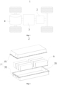
- Fig. 1 is a schematic structural diagram of a vehicle provided by some embodiments of the present application.
- a battery 2 is disposed inside the vehicle 1, and the battery 2 may be disposed in the bottom, head, or tail of the vehicle 1.
- the battery 2 may be used for supplying power to the vehicle 1.
- the battery 2 may be used as an operation power supply of the vehicle 1.
- the vehicle 1 may further include a controller 3 and a motor 4.
- the controller 3 is used for controlling the battery 2 to supply power to the motor 4, for example, for an operating power demand of the vehicle 1 during startup, navigation and running.
- the battery 2 may be used not only as an operation power supply of the vehicle 1, but also as a driving power supply of the vehicle 1 to replace or partially replace fuel or natural gas to provide driving power for the vehicle 1.
- Fig. 2 is an exploded schematic diagram of a battery provided by some embodiments of the present application.
- the battery 2 includes a box 5 and a battery module, a plurality of battery cells 7 form the battery module, and the battery module is accommodated in the box 5.
- the box 5 is used for accommodating the battery cells, and the box 5 may have multiple structures.
- the box 5 may include a first portion 51 and a second portion 52, the first portion 51 and the second portion 52 cover each other, and the first portion 51 and the second portion 52 jointly define an accommodating space 53 for accommodating the battery cells.
- the second portion 52 may be of a hollow structure with an opening at one end, the first portion 51 is of a plate-like structure, and the first portion 51 is fitted on the open side of the second portion 52 to form the box 5 with the accommodating space 53; or each of the first portion 51 and the second portion 52 may be of a hollow structure with an open side, and the open side of the first portion 51 is fitted on the open side of the second portion 52 to form the box 5 with the accommodating space 53.
- the first portion 51 and the second portion 52 may be in various shapes, such as cylindrical or cuboid.
- a sealing member such as a sealant or a sealing ring, may be disposed between the first portion 51 and the second portion 52.
- the first portion 51 may be referred to as an upper box cover, and the second portion 52 may be referred to as a lower box body.
- the plurality of battery cells may be connected in series, in parallel, or in hybrid.
- the hybrid connection refers to a combination of series connection and parallel connection among the plurality of battery cells.
- the plurality of battery cells 7 may be directly connected in series, in parallel, or in hybrid together, and then the whole formed by the plurality of battery cells 7 is accommodated in the box 5.
- the plurality of battery cells 7 may be first connected in series, in parallel, or in hybrid to form a battery module, then a plurality of battery modules are connected in series, in parallel, or in hybrid to form a whole, and the whole is accommodated in the box 5.
- Fig. 3 is an exploded schematic diagram of a battery cell in a battery provided by some embodiments of the present application.
- the battery cell 7 in the embodiments of the present application includes an electrode assembly 11, a shell body 20, and an end cover assembly 30.
- the shell body 20 has an opening 21, the electrode assembly 11 is accommodated in the shell body 20, and the end cover assembly 30 is used for being connected to the shell body 20 and closed to the opening 21.
- At least one electrode assembly 11 is included in a shell 70.
- the electrode assembly 11 includes a positive electrode plate, a negative electrode plate, and a separator.
- the electrode assembly 11 may be a wound electrode assembly, a stacked electrode assembly, or other form of electrode assembly.
- the electrode assembly 11 is a wound electrode assembly.
- the positive electrode plate, the negative electrode plate, and the separator are all strip-shaped structures.
- the positive electrode plate, the separator, and the negative electrode plate may be stacked in sequence and wound for more than two turns to form the electrode assembly 11.
- the electrode assembly 11 is a stacked electrode assembly.
- the electrode assembly 11 includes a plurality of positive electrode plates and a plurality of negative electrode plates, and the positive electrode plates and the negative electrode plates are alternately stacked in a direction parallel to a thickness direction of the positive electrode plates and a thickness direction of the negative electrode plates.
- the battery cell 7 includes at least one electrode assembly 11. That is, in the battery cell 7, one or more electrode assemblies 11 may be accommodated in the shell body 20.
- the battery cell 7 generally includes a shell 70.
- the shell 70 includes a shell body 20 and an end cover assembly 30.
- the shell body 20 is of a hollow structure with an opening on one side.
- the end cover assembly 30 is fitted on the opening of the shell body 20 and forms a sealed connection to form an accommodating cavity for accommodating the electrode assembly 11 and an electrolyte.
- the shell body 20 may be in various shapes, such as cylindrical or cuboid.
- the shape of the shell body 20 may be determined according to a specific shape of the electrode assembly 11. For example, if the electrode assembly 11 is of a cylindrical structure, a cylindrical shell body may be used; or if the electrode assembly 11 is of a cuboid structure, a cuboid shell body may be used.
- the end cover assembly 30 may also be of various structures, such as a plate-like structure or a hollow structure with an opening at one end.
- the shell body 20 is of a cuboid structure
- the end cover assembly 30 is of a plate-like structure
- the end cover assembly 30 is closed to the opening at the top of the shell body 20.
- the end cover assembly 30 further includes an electrode terminal 25.
- two electrode terminals 25 are disposed, and the two electrode terminals 25 are defined as a first electrode terminal and a second electrode terminal respectively.
- the first electrode terminal and the second electrode terminal may be a positive electrode terminal and a negative electrode terminal respectively, or a negative electrode terminal and a positive electrode terminal respectively, which are not limited here.
- the positive electrode terminal and the negative electrode terminal are respectively used for being electrically connected to a positive electrode tab and a negative electrode tab of the electrode assembly 11, so as to output current generated by the electrode assembly 11.
- the end cover assembly 30 further includes a pressure relief mechanism 24, and the pressure relief mechanism 24 is used for releasing internal substances of the battery cell 7 when the internal pressure or temperature of the battery cell 7 reaches a predetermined value, so as to reduce the pressure or temperature of the battery cell 7.
- the pressure relief mechanism 24 is located between the positive electrode terminal and the negative electrode terminal, and the pressure relief mechanism 24 may be a component such as an explosion-proof valve, a rupture disc, a gas valve, a pressure relief valve, or a safety valve.
- the shell body 20 may alternatively be of a hollow structure with openings on two opposite sides.
- the end cover assembly 30 includes two end cover assemblies 30, and the two end cover assemblies 30 are respectively fitted on the two openings of the shell body 20 and form sealed connections to form an accommodating cavity for accommodating the electrode assembly 11 and an electrolyte.
- the positive electrode terminal and the negative electrode terminal may be mounted on the same end cover assembly 30. In other examples, the positive electrode terminal and the negative electrode terminal are mounted on two end cover assemblies 30 respectively.
- a detection module is usually disposed in the battery 2 to detect an operating status of the battery 2.
- Each battery 2 is provided with a chip
- the battery cell 7 is provided with a sensing device
- the chip is connected to the sensing devices of a plurality of battery cells 7 to obtain status information from each battery cell 7, such as voltage and temperature information of the battery cell 7.
- the chip summarizes the information data to obtain operating status information of the entire battery 2.
- the inventors found that the operating statuses of the plurality of battery cells 7 in the battery 2 are greatly different, and if only the status information of the entire battery 2 can be obtained, the conditions of the battery cells 7 cannot be monitored in a timely manner to make corresponding adjustments.
- the inventors designed a battery cell 7, a first detection assembly 801 is disposed in the battery cell 7, the first detection assembly 801 is disposed on a shell 70, and the first detection assembly 801 is configured to detect status information of the battery cell 7.
- the first detection assembly 801 is disposed in the battery cell 7, which can obtain the operating status information of the battery cell 7, monitor the battery cell 7, and find abnormal conditions of the battery cell 7 during operation in a timely manner, thereby improving the operational stability of the battery cell 7 and the safety of the battery 2.
- Fig. 3 is an exploded schematic diagram of a battery cell in a battery provided by some embodiments of the present application
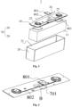
- Fig. 4 is a schematic structural diagram of a first connecting assembly provided by some embodiments of the present application
- Fig. 5 is an enlarged schematic diagram of a circular frame B in Fig. 4
- Fig. 6 is a schematic structural diagram of a first connecting assembly provided by other embodiments of the present application
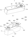
- Fig. 7 is a schematic structural diagram of a battery cell provided by other embodiments of the present application
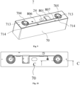
- Fig. 8 is a schematic structural diagram of a battery cell provided by still other embodiments of the present application
- Fig. 9 is a schematic structural diagram of a battery cell provided by some further embodiments of the present application.
- the battery cell 7 in the embodiments of the present application includes a shell 70 and a first detection assembly 801.
- the first detection assembly 801 is disposed on the shell 70, and the first detection assembly 801 is configured to detect status information of the battery cell 7.
- the shell 70 may have various structures, and a shape of the shell 70 is usually square or circular.
- the shell 70 may be made of a metal material having certain strength and corrosion resistance, such as stainless steel or aluminum alloy.
- the first detection assembly 801 is a component for detecting the status information of the battery cell 7 and may include an electronic chip or an electronic computing module, where the electronic chip can analyze and compute some sensor data in the battery cell 7 to obtain the status information of the battery cell 7.
- the voltage information, temperature information, or pressure information in the battery cell 7, obtained by the first detection assembly 801 is greater than or less than a preset value
- monitoring data can be fed back, and an operator can adjust the battery cell 7 alone.
- the corresponding battery cell 7 is repaired, replaced, or the like. Therefore, the above settings can adjust the status of the battery cell 7 in a timely manner, thereby avoiding replacing the entire battery 2, improving the efficiency of maintenance, and prolonging the service life of the entire battery 2.
- the first detection assembly 801 is disposed in the battery cell 7, which can obtain the operating status information of the battery cell 7, monitor the battery cell 7, and find abnormal conditions of the battery cell 7 during operation in a timely manner, thereby improving the operational stability of the battery cell 7 and the safety of the battery 2.
- the status information includes at least one of voltage information, temperature information, deformation information, and pressure information.
- the voltage information refers to an output voltage of the electrode assembly 11 in the battery cell 7.
- a wire may be connected to two output ends of the electrode assembly 11, and a voltage difference between two ends of the wire may be computed to obtain the voltage information of the corresponding battery cell 7.
- a thermally conductive adhesive transmits a change in the temperature of the battery cell 7 to a temperature sensor, and then the temperature sensor sends data to the first detection assembly 801 to obtain the temperature information of the battery cell 7.
- a deformation sensor obtains a deformation quantity of the shell and then transmits the deformation quantity to the first detection assembly 801, and the first detection assembly 801 computes pressure, corresponding to the deformation, of the electrode assembly 10 inside the shell 70, to obtain the pressure information of the battery cell 7.
- the internal operating status of the battery cell 7 can be accurately reflected to ensure the accuracy of detection data.
- the first detection assembly 801 is connected to the shell 70 by any one of bonding, clamping, or welding.
- the above connection method can ensure a firm connection between the first detection assembly 801 and the shell 70 and ensure the safety and reliability of a status monitoring process.
- the battery cell 7 further includes a first connecting assembly 701, and the first detection assembly 801 is connected to the shell 70 through the first connecting assembly 701.
- the first connecting assembly 701 is used for detachably connecting the first detection assembly 801 to the shell 70.
- the above structure can improve the replacement efficiency of the first detection assembly 801.
- the first connecting assembly 701 may be a bolt, a clamping member, or a riveting member.
- the first connecting assembly 701 includes: a first connecting seat 706 and a first connecting block 707.
- the first connecting seat 706 has a first recess, and the first connecting seat 706 is connected to one of the shell 70 or the first detection assembly 801.
- the first connecting block 707 has a first protrusion detachably connected to the first recess, and the first connecting block 707 is connected to the other of the shell 70 or the first detection assembly 801. Due to the detachable connection between the first recess and the first protrusion, the structure is simple and easy to assemble. Therefore, the structure can effectively improve the assembly efficiency and replacement efficiency of the first detection assembly 801.
- the first detection assembly 801 includes a chip.
- the battery cell 7 further includes a second detection assembly disposed at a position for detecting of the battery cell 7.
- the second detection assembly and the first detection assembly 801 are configured to enable wireless communication.
- the second detection assembly may be a sensor for sensing various changing data of the battery cell 7.
- the chip has a data processing and computing function and can compute and convert data from various sensors.
- the chip further has functions of receiving and transmitting signals.
- the chip can transmit data to an external structure or a component such as the sampling assembly of the battery 2 to feed back the status information of the corresponding battery cell 7.
- the wireless communication refers to a data transmission method without physical wiring harnesses.
- the wireless communication can be performed between the first detection assembly 801 and the second detection assembly through infrared signals or Bluetooth signals to transmit data.
- the position for detecting may be a position inside the battery cell 7.
- the position for detecting is used for providing a mounting space to mount the second detection assembly, and meanwhile, the position for detecting can accurately reflect the status of the battery cell 7.
- the second detection assembly is a temperature sensor
- the position for detecting may be on the electrode assembly 11; or when the second detection assembly is a deformation sensor, the position for detecting may be near the pressure relief mechanism 24.
- the above structure can simplify wiring harnesses of the first detection assembly 801 and the second detection assembly, improve the integration of the device, reduce the space occupied by the second detection assembly, and ensure the energy density of the battery cell 7.
- the battery cell 7 includes an electrode assembly 11 and a second connecting assembly 802.
- the electrode assembly 11 is disposed in the shell 70, the chip is disposed on a side, away from the electrode assembly 11, of the shell 70, and the second connecting assembly 802 is configured to electrically connect the electrode assembly 11 to the chip.
- the shell 70 further includes a first electrode terminal 704, the electrode assembly 11 has a positive electrode tab and a negative electrode tab, the shell 70 is electrically connected to one of the positive electrode tab or the negative electrode tab, the first electrode terminal 704 is electrically connected to the other of the positive electrode tab or the negative electrode tab, the chip is disposed in the shell 70 and electrically connected to the shell 70, and the second connecting assembly 802 is connected to the first electrode terminal 704.
- the shell 70 is used as a leading-out end for the positive electrode tab or the negative electrode tab, and the first electrode terminal 704 is used as the other leading-out end, thereby simplifying the structure of the battery cell 7. Meanwhile, the second connecting assembly 802 and the chip are connected to the two leading-out ends respectively, which can achieve data transmission between the first connecting assembly 701 and the chip.
- the above structure is simple, and improves the integration of the device, while ensuring the efficiency of detection data transmission
- the electrode assembly 11 has a positive electrode tab 101 and a negative electrode tab 102
- the second connecting assembly 802 includes a first connecting wire 806 and a second connecting wire 807
- the first connecting wire 806 is electrically connected to the positive electrode tab 101
- the second connecting wire 807 is electrically connected to the negative electrode tab 102.
- first connecting wire 806 and the second connecting wire 807 may be connected to the electrode tabs of the battery cell 7 by welding, hot melt connection, or the like.
- the first connecting wire 806 and the second connecting wire 807 are directly connected to the positive electrode tab 101 and the negative electrode tab 102, which can improve the efficiency of obtaining status information by the second detection assembly and ensure the accuracy of detection data.
- the shell 70 includes a first electrode terminal 704 electrically connected to the positive electrode tab 101, and the first connecting wire 806 is connected to the first electrode terminal 704.
- the shell 70 further includes a second electrode terminal 705 electrically connected to the negative electrode tab 102, and the second connecting wire 807 is connected to the second electrode terminal 705.
- the first connecting wire 806 is connected to the first electrode terminal 704, which facilitates the connection operation of the first connecting wire 806 and improves the convenience of assembling the second detection assembly.
- an avoidance structure 714 is disposed on an end surface, away from the electrode assembly 11, of the first electrode terminal 704 or the second electrode terminal 705.
- an avoidance structure 714 is disposed on an end surface, away from the electrode assembly 11, of each of the first electrode terminal 704 and the second electrode terminal 705. The avoidance structure 714 is used for accommodating an end portion of the second connecting assembly 802.
- the avoidance structure 714 may be formed by inward depression of a part of a surface of an end portion of the first electrode terminal 704 or the second electrode terminal 705.
- the end portion of the second connecting assembly 802 can be exposed by the avoidance structure 714.
- the protruding height of the second connecting assembly 802 on the surface of the electrode terminal is reduced, and the interference between the end portion of the second connecting assembly 802 and another component connected to the end portion of the electrode terminal is reduced.
- the shell 70 is provided with a connecting hole 809, and the end portion of the second connecting assembly 802 passes through the connecting hole 809 and is connected to the electrode assembly 11.
- the connecting hole 809 may be a through hole passing through in a thickness direction of a wall of the shell 70, and the connecting hole 809 should be close to the position for detecting of the battery cell 7, so as to reduce the wiring length of the second connecting assembly 802 as much as possible.
- the connecting hole 809 may be a liquid injection hole 808 on the shell 70.
- the second connecting assembly 802 directly passes through the injection hole 808 and is connected to the electrode assembly 11, which can reduce a quantity of perforations in the shell 70 and improve efficiency.
- the connecting hole 809 facilitates passing of the end portion of the second connecting assembly 802 through the shell 70 and connection to the electrode assembly 11 in the shell 70.
- the battery cell 7 further includes a connecting sheet 712, and one end of the second connecting assembly 802 is connected to the connecting sheet 712.
- the second connecting assembly 802 may be a wire with an insulating layer, and an end portion of the wire is welded to the connecting sheet 712 to achieve connection.
- the connecting sheet 712 may be a sheet-like conductor, one side of the connecting sheet 712 is used for being welded to the positive electrode tab 101 or the negative electrode tab 102 of the electrode assembly 11, and the other side of the connecting sheet 712 is used for being connected to the electrode terminal.
- the connecting sheet 712 can lead out the current of the electrode assembly 11 and fix the tab.
- Accurate monitoring data can be obtained by connecting the second connecting assembly 802 to the connecting sheet 712. Meanwhile, the welding position on the surface of the connecting sheet 712 can be effectively utilized to ensure the fixing of the welding position at the end portion of the first connecting assembly 701 and ensure the stability of connection.
- the second detection assembly includes a deformation sensor
- the shell 70 includes a pressure relief mechanism 24, and the deformation sensor is disposed near or on the pressure relief mechanism 24.
- the deformation sensor is disposed on or near the pressure relief mechanism 24 to accurately obtain deformation data of the pressure relief mechanism 24, and the position can ensure the accuracy and sensitivity of the deformation data, improve detection efficiency, reflect an abnormal status of the battery cell 7 in a timely manner, and further ensure the safety of the battery cell 7.
- the second detection assembly includes a temperature sensor, and the temperature sensor is disposed on a side, facing the electrode assembly 11, of the shell 70, or the temperature sensor is disposed on the electrode assembly 11.
- the temperature sensor is used for obtaining temperature information of the electrode assembly 11, which can reflect the operating status of internal substances in the battery cell 7 in a timely manner.
- the temperature of the battery cell 7 is too high, feedback can be provided in a timely manner and thus the probability of failure or explosion of the battery cell 7 is reduced.
- the shell 70 includes an end cover, and the first electrode terminal 704 and/or the second electrode terminal 705 are disposed on the end cover 30.
- the first electrode terminal 704 or the second electrode terminal 705 is disposed on the end cover 30 to facilitate the connection of the first electrode terminal 704 and the second electrode terminal 705 with external components or devices.
- An embodiment of the present application further provides a battery 2, including the battery cell 7 in the foregoing embodiments.
- the battery 2 further includes a sampling assembly.
- the sampling assembly is connected to the first detection assemblies 801 of at least some battery cells 7 to obtain status information of the battery cells 7.
- the sampling assembly statistics on data from a plurality of battery cells 7 can be made to reflect the operating status of the entire battery 2, facilitate a user to monitor the overall status of the battery 2, and adjust or replace abnormal battery cells 7 in a timely manner, thereby ensuring the safe and stable operation of the entire battery 2 and prolonging the service life of the battery 2.
- Embodiments of the present application further provide an electricity consuming apparatus including the battery 2 in the foregoing embodiments for providing electrical energy.
- the technical solution described in the embodiment of the present application is applicable to the battery 2 and the electricity consuming apparatus using the battery 2.
- the electricity consuming apparatus may be a vehicle 1, a mobile phone, a portable device, a notebook computer, a ship, a spacecraft, an electric toy, an electric tool, or the like.
- the vehicle 1 may be an oil-fueled vehicle, a gas vehicle, or a new energy vehicle.
- the new energy vehicle may be a battery electric vehicle, a hybrid electric vehicle, an extended-range vehicle, or the like.
- the spacecraft includes an airplane, a rocket, a space shuttle, a spaceship, or the like.
- the electric toy includes a fixed or mobile electric toy, such as a game console, an electric car toy, an electric ship toy, or an electric aircraft toy.
- the electric tool includes a metal cutting electric tool, a grinding electric tool, an assembly electric tool, or a railway electric tool, such as an electric drill, an electric grinder, an electric wrench, an electric screwdriver, an electric hammer, an impact electric drill, a concrete vibrator, or an electric planer.
- a metal cutting electric tool such as an electric drill, an electric grinder, an electric wrench, an electric screwdriver, an electric hammer, an impact electric drill, a concrete vibrator, or an electric planer.
- the battery 2 in the embodiments of the present application includes a battery cell 7, and a first detection assembly 801 is disposed in the battery cell 7.
- the first detection assembly 801 is disposed in the battery cell 7, which can obtain operating status information of the battery cell 7, monitor the battery cell 7, and find abnormal conditions of the battery cell 7 during operation in a timely manner, thereby improving the operational stability of the battery cell 7 and the safety of the battery 2 and prolonging the service life of the battery 2. Therefore, the battery cell 7, the battery 2, and the electricity consuming apparatus provided in the embodiments of the present application can also achieve the above technical effects due to the first detection assembly 801, which will not be elaborated here.
Landscapes
- Chemical & Material Sciences (AREA)
- Chemical Kinetics & Catalysis (AREA)
- Electrochemistry (AREA)
- General Chemical & Material Sciences (AREA)
- Engineering & Computer Science (AREA)
- Manufacturing & Machinery (AREA)
- Microelectronics & Electronic Packaging (AREA)
- Aviation & Aerospace Engineering (AREA)
- Computer Networks & Wireless Communication (AREA)
- Battery Mounting, Suspending (AREA)
Abstract
Description
- The present application relates to the field of batteries, and in particular, to a battery cell, a battery, and an electricity consuming apparatus.
- Batteries are widely used in electronic devices, such as mobile phones, laptops, electric scooters, electric cars, electric airplanes, electric ships, electric toy cars, electric toy ships, electric toy planes, and electric tools. The batteries may include cadmium nickel batteries, hydrogen nickel batteries, lithium-ion batteries, secondary alkaline zinc manganese batteries, and the like.
- In the development of battery technologies, the research has always focused on the improvement on the performance of batteries. At present, how to improve the safety performance and operational stability of batteries is also one of the research focuses in the art.
- In view of the above problems, the present application provides a battery cell, a battery, and an electricity consuming apparatus to improve the safety performance and operational stability of the battery.
- In a first aspect, the present application provides a battery cell, including a shell and a first detection assembly, where the first detection assembly is located on the shell, and the first detection assembly is configured to detect status information of the battery cell.
- In the technical solution of embodiments of the present application, the first detection assembly is disposed in the battery cell, which can obtain the operating status information of the battery cell, monitor the battery cell, and find abnormal conditions of the battery cell during operation in a timely manner, thereby improving the operational stability of the battery cell and the safety of the battery.
- In some embodiments, the status information includes at least one of voltage information, temperature information, deformation information, and pressure information. By monitoring the status information, the internal operating status of the battery cell can be accurately reflected to ensure the accuracy of detection data.
- In some embodiments, the first detection assembly is connected to the shell by any one of bonding, clamping, or welding. The above connection method can ensure a firm connection between the first detection assembly and the shell and ensure the safety and reliability of the status monitoring process.
- In some embodiments, the battery cell further includes a first connecting assembly, and the first detection assembly is connected to the shell through the first connecting assembly.
- In some embodiments, the first connecting assembly is configured to detachably connect the first detection assembly to the shell. The above structure can improve the replacement efficiency of the first detection assembly.
- In some embodiments, the first connecting assembly includes: a first connecting seat and a first connecting block. The first connecting seat has a first recess, and the first connecting seat is connected to one of the shell or the first detection assembly. The first connecting block has a first protrusion detachably connected to the first recess, and the first connecting block is connected to the other of the shell or the first detection assembly. Due to the detachable connection between the first recess and the first protrusion, the structure is simple and easy to assemble. Therefore, the structure can effectively improve the assembly efficiency and replacement efficiency of the first detection assembly.
- In some embodiments, the first detection assembly includes a chip. The battery cell further includes a second detection assembly disposed at a position for detecting of the battery cell. The second detection assembly and the first detection assembly are configured to enable wireless communication. The above structure can simplify wiring harnesses of the first detection assembly and the second detection assembly, improve the integration of a device, reduce the space occupied by the second detection assembly, and ensure the energy density of the battery cell.
- In some embodiments, the battery cell comprises an electrode assembly and a second connecting assembly. The electrode assembly is disposed in the shell, the chip is disposed on a side, away from the electrode assembly, of the shell, and the second connecting assembly is configured to electrically connect the electrode assembly to the chip.
- In some embodiments, the shell further includes a first electrode terminal, the electrode assembly has a positive electrode tab and a negative electrode tab, the shell is electrically connected to one of the positive electrode tab or the negative electrode tab, the first electrode terminal is electrically connected to the other of the positive electrode tab or the negative electrode tab, the chip is disposed on the shell and electrically connected to the shell, and the second connecting assembly is connected to the first electrode terminal. The shell is used as a leading-out end for the positive electrode tab or the negative electrode tab, and the first electrode terminal is used as the other leading-out end, thereby simplifying the structure of the battery cell. Meanwhile, the second connecting assembly and the chip are connected to the two leading-out ends respectively, which can achieve data transmission between the first connecting assembly and the chip. The above structure is simple, and improves the integration of the device, while ensuring the efficiency of detection data transmission.
- In some embodiments, the electrode assembly has a positive electrode tab and a negative electrode tab, the second connecting assembly includes a first connecting wire and a second connecting wire, the first connecting wire is electrically connected to the positive electrode tab, and the second connecting wire is electrically connected to the negative electrode tab. The first connecting wire and the second connecting wire are directly connected to the positive electrode tab and the negative electrode tab, which can improve the efficiency of obtaining status information by the second detection assembly and ensure the accuracy of detection data.
- In some embodiments, the shell includes a first electrode terminal electrically connected to the positive electrode tab, the first connecting wire is connected to the first electrode terminal, and/or the shell includes a second electrode terminal electrically connected to the negative electrode tab, and the second connecting wire is connected to the second electrode terminal. The first connecting wire is connected to the first electrode terminal, which facilitates the connection operation of the first connecting wire and improves the convenience of assembling the second detection assembly.
- In some embodiments, an avoidance structure is disposed on an end surface, away from the electrode assembly, of the first electrode terminal and/or the second electrode terminal, and the avoidance structure is configured to accommodate an end portion of the second connecting assembly. By setting the avoidance structure, the protruding height of the second connecting assembly on the surface of the electrode terminal is reduced, and the interference between the end portion of the second connecting assembly and another component connected to the end portion of the electrode terminal is reduced.
- In some embodiments, the shell is provided with a connecting hole, and the end portion of the second connecting assembly passes through the connecting hole and is connected to the electrode assembly. The connecting hole facilitates the end portion of the second connecting assembly to pass through the shell and be connected to the electrode assembly in the shell.
- In some embodiments, the battery cell further includes a connecting sheet, and one end of the second connecting assembly is connected to the connecting sheet.
- In some embodiments, the second detection assembly includes a deformation sensor, the shell includes a pressure relief mechanism, and the deformation sensor is disposed near or on the pressure relief mechanism. The deformation sensor is disposed on or near the pressure relief mechanism to accurately obtain deformation data of the pressure relief mechanism, and the position can ensure the accuracy and sensitivity of the deformation data, improve detection efficiency, reflect an abnormal status of the battery cell in a timely manner, and further ensure the safety of the battery cell.
- In some embodiments, the second detection assembly includes a temperature sensor, and the temperature sensor is disposed on a side, facing the electrode assembly, of the shell, or the temperature sensor is disposed on the electrode assembly. The temperature sensor is used for obtaining temperature information of the electrode assembly, which can reflect the operating status of internal substances in the battery cell in a timely manner. When the temperature of the battery cell is too high, feedback can be provided in a timely manner, and thus the probability of failure or explosion of the
battery cell 7 is reduced. - In some embodiments, the shell includes an end cover, and the first electrode terminal and/or the second electrode terminal are disposed on the end cover. The first electrode terminal or the second electrode terminal is disposed on the end cover to facilitate the connection of the first electrode terminal and the second electrode terminal with external components.
- In a second aspect, the present application further provides a battery, including the battery cell in the foregoing embodiments.
- In some embodiments, the battery further includes a sampling assembly, and the sampling assembly is connected to the first detection assemblies of at least some battery cells to obtain status information of the battery cells. By setting the sampling assembly, statistics on data from a plurality of battery cells can be made to reflect the operating status of the entire battery and facilitate a user to monitor the overall status of the battery.
- In a third aspect, the present application further provides an electricity consuming apparatus, including the battery in the foregoing embodiments for providing electrical energy.
- The above description is only a summary of the technical solutions of the present application. In order to understand the technical means in the present application more clearly, it can be implemented in accordance with the content of the specification; and in order to make the above and other objectives, features and advantages of the present application more obvious and easier to understand, and the specific embodiments of the present application are cited below.
- Features, advantages, and technical effects of exemplary embodiments of the present application will be described below with reference to the accompanying drawings.
-
Fig. 1 is a schematic structural diagram of a vehicle provided by some embodiments of the present application; -
Fig. 2 is an exploded schematic diagram of a battery provided by some embodiments of the present application; -
Fig. 3 is an exploded schematic diagram of a battery cell in a battery provided by some embodiments of the present application; -
Fig. 4 is a schematic structural diagram of a first connecting assembly provided by some embodiments of the present application; -
Fig. 5 is an enlarged schematic diagram of a circular frame B inFig. 4 ; -
Fig. 6 is a schematic structural diagram of a first connecting assembly provided by other embodiments of the present application; -
Fig. 7 is a schematic structural diagram of a battery cell provided by other embodiments of the present application; -
Fig. 8 is a schematic structural diagram of a battery cell provided by still other embodiments of the present application; -
Fig. 9 is a schematic structural diagram of a battery cell provided by some further embodiments of the present application; -
Fig. 10 is a schematic structural diagram of an end cover of a battery cell provided by some embodiments of the present application; -
Fig. 11 is a schematic structural diagram of a C-C section inFig. 10 ; and -
Fig. 12 is an enlarged schematic diagram of a circular frame D inFig. 11 . - The accompanying drawings are not drawn to actual scale.
- Reference numerals are described as follows:
1. Vehicle; 2. Battery; 20. Shell body; 21. Opening; 24. Pressure relief mechanism; 25. Electrode terminal; 3. Controller; 4. Motor; 5. Box; 51. First portion; 52. Second portion; 53. Accommodating space; 7. Battery cell; 70. Shell; 11. Electrode assembly; 701. First connecting assembly; 801. First detection assembly; 802. Second connecting assembly; 706. First connecting seat; 707. First connecting block; 708. Second connecting seat; 709. Second connecting block; 704. First electrode terminal; 806. First connecting wire; 807. Second connecting wire; 704. First electrode terminal; 705. Second electrode terminal; 712. Connecting sheet; 101. Positive electrode tab; 102. Negative electrode tab; 714. Avoidance structure; 808. Liquid injection hole; 809. Connecting hole. - To make the objectives, technical solutions and advantages of the embodiments of the present application clearer, the technical solutions in the embodiments of the present application will be described clearly below with reference to the accompanying drawings in the embodiments of the present application. Apparently, the described embodiments are some but not all of the embodiments of the present application. All other embodiments obtained by those of ordinary skill in the art based on the embodiments of the present application without creative efforts shall fall within the protection scope of the present application.
- Unless otherwise defined, all technical and scientific terms used in the present application have the same meanings as those commonly understood by technical personnel in the technical field of the present application; the terms used in the specification of the present application are only for the purpose of describing specific embodiments and are not intended to limit the present application; and the terms "include" and "have" in the specification and claims of the present application, the accompanying drawings, and any variations thereof, are intended to cover non-exclusive inclusion. The terms "first", "second", and the like in the specification and claims of the present application or the accompanying drawings are used to distinguish different objects, rather than to describe specific sequences or primary and secondary relationships.
- The "embodiment" mentioned in the present application means that specific features, structures or characteristics described in conjunction with the embodiment may be included in at least one embodiment of the present application. The phrase at various locations in the specification does not necessarily refer to the same embodiment, or an independent or alternative embodiment exclusive of another embodiment.
- In the description of the present application, it should be noted that, unless otherwise specified and defined, the terms "mounted", "connected", "connection", and "attached" should be broadly understood, for example, the "connection" may be a fixed connection, a detachable connection, an integral connection, a direct connection, a connection through a medium, or a communication of interiors of two elements. Those of ordinary skill in the art may understand the specific meanings of the above terms in the present application according to specific circumstances.
- The term "and/or" in the present application is merely an association relationship for describing associated objects, and represents that three relationships may exist. For example, A and/or B may represent the following three cases: A exists alone, both A and B exist, and B exists alone. In addition, the character "/" in the present application generally indicates an "or" relationship between the associated objects.
- In the embodiments of the present application, the same reference numerals represent the same components, and for simplicity, detailed descriptions of the same components are omitted in different embodiments. It should be understood that, in the embodiments of the present application shown in the accompanying drawings, dimensions of various components and integrated apparatuses, such as thickness, length, and width, are only illustrative and should not constitute any limitations on the present application.
- In the present application, "a plurality of" means two (inclusive) or more.
- In the present application, the battery cells may include lithium-ion secondary battery cells, lithium-ion primary battery cells, lithium-sulfur battery cells, sodium lithium-ion battery cells, sodium-ion battery cells, magnesium-ion battery cells, or the like, which are not limited by the embodiments of the present application. The battery cells may be cylindrical, flat, cuboid, or in other shapes, which is also not limited by the embodiments of the present application. The battery cells are generally divided into three types according to ways of packaging: cylindrical battery cells, square battery cells and soft package battery cells, which are also not limited in the embodiments of the present application.
- The battery mentioned in the embodiments of the present application refers to a single physical module that includes one or more battery cells to provide higher voltage and capacity. For example, the battery mentioned in the present application may include a battery module or a battery pack. The battery generally includes a shell used for packaging one or more battery cells. The shell may prevent liquid or other foreign matters from affecting charging or discharging of the battery cells.
- The battery cell includes an electrode assembly and an electrolyte, and the electrode assembly includes a positive electrode plate, a negative electrode plate, and a separator. The battery cell mainly relies on migration of metal ions between the positive electrode plate and the negative electrode plate to work. The positive electrode plate includes a positive electrode current collector and a positive electrode active material layer applied on a surface of the positive electrode current collector; and the positive electrode current collector includes a positive electrode current collecting portion and a positive electrode protrusion protruding from the positive electrode current collecting portion, the positive electrode current collecting portion is coated with the positive electrode active material layer, at least a portion of the positive electrode protrusion is not coated with the positive electrode active material layer, and the positive electrode protrusion serves as a positive electrode tab. Taking a lithium-ion battery as an example, a material for the positive electrode current collector may be aluminum, the positive electrode active material layer includes a positive electrode active material, and the positive electrode active material may be lithium cobalt oxide, lithium iron phosphate, ternary lithium, lithium manganate, or the like. The negative electrode plate includes a negative electrode current collector and a negative electrode active material layer applied on a surface of the negative electrode current collector; and the negative electrode current collector includes a negative electrode current collecting portion and a negative electrode protrusion protruding from the negative electrode current collecting portion, the negative electrode current collecting portion is coated with the negative electrode active material layer, at least a portion of the negative electrode protrusion is not coated with the negative electrode active material layer, and the negative electrode protrusion serves as a negative electrode tab. A material for the negative electrode current collector may be copper, the negative electrode active material layer includes a negative electrode active material, and the negative electrode active material may be carbon, silicon, or the like. In order to ensure that no fusing occurs when high current passes through, there is a plurality of positive electrode tabs stacked together, and there is a plurality of negative electrode tabs stacked together. A material for the separator may be polypropylene (PP), polyethylene (PE), or the like. Moreover, the electrode assembly may be of a wound structure or a stacked structure, and the embodiments of the present application are not limited thereto.
- For convenient description, the following embodiments are described by an example of a vehicle as an electricity consuming apparatus.
-
Fig. 1 is a schematic structural diagram of a vehicle provided by some embodiments of the present application. As shown inFig. 1 , abattery 2 is disposed inside thevehicle 1, and thebattery 2 may be disposed in the bottom, head, or tail of thevehicle 1. Thebattery 2 may be used for supplying power to thevehicle 1. For example, thebattery 2 may be used as an operation power supply of thevehicle 1. - The
vehicle 1 may further include acontroller 3 and amotor 4. Thecontroller 3 is used for controlling thebattery 2 to supply power to themotor 4, for example, for an operating power demand of thevehicle 1 during startup, navigation and running. - In some embodiments of the present application, the
battery 2 may be used not only as an operation power supply of thevehicle 1, but also as a driving power supply of thevehicle 1 to replace or partially replace fuel or natural gas to provide driving power for thevehicle 1. -
Fig. 2 is an exploded schematic diagram of a battery provided by some embodiments of the present application. As shown inFig. 2 , thebattery 2 includes abox 5 and a battery module, a plurality ofbattery cells 7 form the battery module, and the battery module is accommodated in thebox 5. - The
box 5 is used for accommodating the battery cells, and thebox 5 may have multiple structures. In some embodiments, thebox 5 may include afirst portion 51 and asecond portion 52, thefirst portion 51 and thesecond portion 52 cover each other, and thefirst portion 51 and thesecond portion 52 jointly define anaccommodating space 53 for accommodating the battery cells. Thesecond portion 52 may be of a hollow structure with an opening at one end, thefirst portion 51 is of a plate-like structure, and thefirst portion 51 is fitted on the open side of thesecond portion 52 to form thebox 5 with theaccommodating space 53; or each of thefirst portion 51 and thesecond portion 52 may be of a hollow structure with an open side, and the open side of thefirst portion 51 is fitted on the open side of thesecond portion 52 to form thebox 5 with theaccommodating space 53. Thefirst portion 51 and thesecond portion 52 may be in various shapes, such as cylindrical or cuboid. - To improve the sealing property after the
first portion 51 is connected to thesecond portion 52, a sealing member, such as a sealant or a sealing ring, may be disposed between thefirst portion 51 and thesecond portion 52. - Assuming that the
first portion 51 is closed to a top of thesecond portion 52, thefirst portion 51 may be referred to as an upper box cover, and thesecond portion 52 may be referred to as a lower box body. - There may be one or more battery cells in the
battery 2. If there is a plurality of battery cells, the plurality of battery cells may be connected in series, in parallel, or in hybrid. The hybrid connection refers to a combination of series connection and parallel connection among the plurality of battery cells. The plurality ofbattery cells 7 may be directly connected in series, in parallel, or in hybrid together, and then the whole formed by the plurality ofbattery cells 7 is accommodated in thebox 5. Alternatively, the plurality ofbattery cells 7 may be first connected in series, in parallel, or in hybrid to form a battery module, then a plurality of battery modules are connected in series, in parallel, or in hybrid to form a whole, and the whole is accommodated in thebox 5. -
Fig. 3 is an exploded schematic diagram of a battery cell in a battery provided by some embodiments of the present application. Thebattery cell 7 in the embodiments of the present application includes anelectrode assembly 11, ashell body 20, and anend cover assembly 30. Theshell body 20 has anopening 21, theelectrode assembly 11 is accommodated in theshell body 20, and theend cover assembly 30 is used for being connected to theshell body 20 and closed to theopening 21. - At least one
electrode assembly 11 is included in ashell 70. For example, theelectrode assembly 11 includes a positive electrode plate, a negative electrode plate, and a separator. Theelectrode assembly 11 may be a wound electrode assembly, a stacked electrode assembly, or other form of electrode assembly. - In some embodiments, the
electrode assembly 11 is a wound electrode assembly. The positive electrode plate, the negative electrode plate, and the separator are all strip-shaped structures. In the embodiments of the present application, the positive electrode plate, the separator, and the negative electrode plate may be stacked in sequence and wound for more than two turns to form theelectrode assembly 11. - In other embodiments, the
electrode assembly 11 is a stacked electrode assembly. Specifically, theelectrode assembly 11 includes a plurality of positive electrode plates and a plurality of negative electrode plates, and the positive electrode plates and the negative electrode plates are alternately stacked in a direction parallel to a thickness direction of the positive electrode plates and a thickness direction of the negative electrode plates. - The
battery cell 7 includes at least oneelectrode assembly 11. That is, in thebattery cell 7, one ormore electrode assemblies 11 may be accommodated in theshell body 20. - The
battery cell 7 generally includes ashell 70. Theshell 70 includes ashell body 20 and anend cover assembly 30. Theshell body 20 is of a hollow structure with an opening on one side. Theend cover assembly 30 is fitted on the opening of theshell body 20 and forms a sealed connection to form an accommodating cavity for accommodating theelectrode assembly 11 and an electrolyte. - The
shell body 20 may be in various shapes, such as cylindrical or cuboid. The shape of theshell body 20 may be determined according to a specific shape of theelectrode assembly 11. For example, if theelectrode assembly 11 is of a cylindrical structure, a cylindrical shell body may be used; or if theelectrode assembly 11 is of a cuboid structure, a cuboid shell body may be used. Theend cover assembly 30 may also be of various structures, such as a plate-like structure or a hollow structure with an opening at one end. For example, theshell body 20 is of a cuboid structure, theend cover assembly 30 is of a plate-like structure, and theend cover assembly 30 is closed to the opening at the top of theshell body 20. - The
end cover assembly 30 further includes anelectrode terminal 25. In some embodiments, twoelectrode terminals 25 are disposed, and the twoelectrode terminals 25 are defined as a first electrode terminal and a second electrode terminal respectively. The first electrode terminal and the second electrode terminal may be a positive electrode terminal and a negative electrode terminal respectively, or a negative electrode terminal and a positive electrode terminal respectively, which are not limited here. The positive electrode terminal and the negative electrode terminal are respectively used for being electrically connected to a positive electrode tab and a negative electrode tab of theelectrode assembly 11, so as to output current generated by theelectrode assembly 11. - The
end cover assembly 30 further includes apressure relief mechanism 24, and thepressure relief mechanism 24 is used for releasing internal substances of thebattery cell 7 when the internal pressure or temperature of thebattery cell 7 reaches a predetermined value, so as to reduce the pressure or temperature of thebattery cell 7. For example, thepressure relief mechanism 24 is located between the positive electrode terminal and the negative electrode terminal, and thepressure relief mechanism 24 may be a component such as an explosion-proof valve, a rupture disc, a gas valve, a pressure relief valve, or a safety valve. - In some embodiments, the
shell body 20 may alternatively be of a hollow structure with openings on two opposite sides. Theend cover assembly 30 includes twoend cover assemblies 30, and the twoend cover assemblies 30 are respectively fitted on the two openings of theshell body 20 and form sealed connections to form an accommodating cavity for accommodating theelectrode assembly 11 and an electrolyte. In some examples, the positive electrode terminal and the negative electrode terminal may be mounted on the sameend cover assembly 30. In other examples, the positive electrode terminal and the negative electrode terminal are mounted on twoend cover assemblies 30 respectively. - A detection module is usually disposed in the
battery 2 to detect an operating status of thebattery 2. Eachbattery 2 is provided with a chip, thebattery cell 7 is provided with a sensing device, and the chip is connected to the sensing devices of a plurality ofbattery cells 7 to obtain status information from eachbattery cell 7, such as voltage and temperature information of thebattery cell 7. Then the chip summarizes the information data to obtain operating status information of theentire battery 2. However, during use, the inventors found that the operating statuses of the plurality ofbattery cells 7 in thebattery 2 are greatly different, and if only the status information of theentire battery 2 can be obtained, the conditions of thebattery cells 7 cannot be monitored in a timely manner to make corresponding adjustments. - In view of the above problems, the inventors designed a
battery cell 7, afirst detection assembly 801 is disposed in thebattery cell 7, thefirst detection assembly 801 is disposed on ashell 70, and thefirst detection assembly 801 is configured to detect status information of thebattery cell 7. - According to the technical solution of the embodiments of the present application, the
first detection assembly 801 is disposed in thebattery cell 7, which can obtain the operating status information of thebattery cell 7, monitor thebattery cell 7, and find abnormal conditions of thebattery cell 7 during operation in a timely manner, thereby improving the operational stability of thebattery cell 7 and the safety of thebattery 2. - Continue to refer to
Fig. 3 to Fig. 9 , whereFig. 3 is an exploded schematic diagram of a battery cell in a battery provided by some embodiments of the present application;Fig. 4 is a schematic structural diagram of a first connecting assembly provided by some embodiments of the present application;Fig. 5 is an enlarged schematic diagram of a circular frame B inFig. 4 ;Fig. 6 is a schematic structural diagram of a first connecting assembly provided by other embodiments of the present application;Fig. 7 is a schematic structural diagram of a battery cell provided by other embodiments of the present application;Fig. 8 is a schematic structural diagram of a battery cell provided by still other embodiments of the present application; andFig. 9 is a schematic structural diagram of a battery cell provided by some further embodiments of the present application. - As shown in
Fig. 3 and Fig. 4 , thebattery cell 7 in the embodiments of the present application includes ashell 70 and afirst detection assembly 801. Thefirst detection assembly 801 is disposed on theshell 70, and thefirst detection assembly 801 is configured to detect status information of thebattery cell 7. - Specifically, the
shell 70 may have various structures, and a shape of theshell 70 is usually square or circular. Theshell 70 may be made of a metal material having certain strength and corrosion resistance, such as stainless steel or aluminum alloy. - The
first detection assembly 801 is a component for detecting the status information of thebattery cell 7 and may include an electronic chip or an electronic computing module, where the electronic chip can analyze and compute some sensor data in thebattery cell 7 to obtain the status information of thebattery cell 7. - When the voltage information, temperature information, or pressure information in the
battery cell 7, obtained by thefirst detection assembly 801 is greater than or less than a preset value, monitoring data can be fed back, and an operator can adjust thebattery cell 7 alone. For example, the correspondingbattery cell 7 is repaired, replaced, or the like. Therefore, the above settings can adjust the status of thebattery cell 7 in a timely manner, thereby avoiding replacing theentire battery 2, improving the efficiency of maintenance, and prolonging the service life of theentire battery 2. - In the technical solution of the embodiment of the present application, the
first detection assembly 801 is disposed in thebattery cell 7, which can obtain the operating status information of thebattery cell 7, monitor thebattery cell 7, and find abnormal conditions of thebattery cell 7 during operation in a timely manner, thereby improving the operational stability of thebattery cell 7 and the safety of thebattery 2. - In some embodiments of the present application, the status information includes at least one of voltage information, temperature information, deformation information, and pressure information.
- Specifically, the voltage information refers to an output voltage of the
electrode assembly 11 in thebattery cell 7. For example, a wire may be connected to two output ends of theelectrode assembly 11, and a voltage difference between two ends of the wire may be computed to obtain the voltage information of thecorresponding battery cell 7. For the temperature information, a thermally conductive adhesive transmits a change in the temperature of thebattery cell 7 to a temperature sensor, and then the temperature sensor sends data to thefirst detection assembly 801 to obtain the temperature information of thebattery cell 7. For the pressure information, a deformation sensor obtains a deformation quantity of the shell and then transmits the deformation quantity to thefirst detection assembly 801, and thefirst detection assembly 801 computes pressure, corresponding to the deformation, of the electrode assembly 10 inside theshell 70, to obtain the pressure information of thebattery cell 7. - By monitoring the status information, the internal operating status of the
battery cell 7 can be accurately reflected to ensure the accuracy of detection data. - In some embodiments of the present application, the
first detection assembly 801 is connected to theshell 70 by any one of bonding, clamping, or welding. The above connection method can ensure a firm connection between thefirst detection assembly 801 and theshell 70 and ensure the safety and reliability of a status monitoring process. - In some embodiments of the present application, as shown in
Figs. 4 to 6 , thebattery cell 7 further includes a first connectingassembly 701, and thefirst detection assembly 801 is connected to theshell 70 through the first connectingassembly 701. - In some embodiments of the present application, the first connecting
assembly 701 is used for detachably connecting thefirst detection assembly 801 to theshell 70. The above structure can improve the replacement efficiency of thefirst detection assembly 801. For example, the first connectingassembly 701 may be a bolt, a clamping member, or a riveting member. - In some embodiments of the present application, the first connecting
assembly 701 includes: a first connectingseat 706 and a first connectingblock 707. The first connectingseat 706 has a first recess, and the first connectingseat 706 is connected to one of theshell 70 or thefirst detection assembly 801. The first connectingblock 707 has a first protrusion detachably connected to the first recess, and the first connectingblock 707 is connected to the other of theshell 70 or thefirst detection assembly 801. Due to the detachable connection between the first recess and the first protrusion, the structure is simple and easy to assemble. Therefore, the structure can effectively improve the assembly efficiency and replacement efficiency of thefirst detection assembly 801. - In some embodiments of the present application, the
first detection assembly 801 includes a chip. Thebattery cell 7 further includes a second detection assembly disposed at a position for detecting of thebattery cell 7. The second detection assembly and thefirst detection assembly 801 are configured to enable wireless communication. - For example, the second detection assembly may be a sensor for sensing various changing data of the
battery cell 7. The chip has a data processing and computing function and can compute and convert data from various sensors. In addition, the chip further has functions of receiving and transmitting signals. The chip can transmit data to an external structure or a component such as the sampling assembly of thebattery 2 to feed back the status information of thecorresponding battery cell 7. The wireless communication refers to a data transmission method without physical wiring harnesses. For example, the wireless communication can be performed between thefirst detection assembly 801 and the second detection assembly through infrared signals or Bluetooth signals to transmit data. - The position for detecting may be a position inside the
battery cell 7. The position for detecting is used for providing a mounting space to mount the second detection assembly, and meanwhile, the position for detecting can accurately reflect the status of thebattery cell 7. For example, when the second detection assembly is a temperature sensor, the position for detecting may be on theelectrode assembly 11; or when the second detection assembly is a deformation sensor, the position for detecting may be near thepressure relief mechanism 24. - The above structure can simplify wiring harnesses of the
first detection assembly 801 and the second detection assembly, improve the integration of the device, reduce the space occupied by the second detection assembly, and ensure the energy density of thebattery cell 7. - In some embodiments of the present application, the
battery cell 7 includes anelectrode assembly 11 and a second connectingassembly 802. Theelectrode assembly 11 is disposed in theshell 70, the chip is disposed on a side, away from theelectrode assembly 11, of theshell 70, and the second connectingassembly 802 is configured to electrically connect theelectrode assembly 11 to the chip. - In some embodiments of the present application, as shown in
Fig. 7 , theshell 70 further includes afirst electrode terminal 704, theelectrode assembly 11 has a positive electrode tab and a negative electrode tab, theshell 70 is electrically connected to one of the positive electrode tab or the negative electrode tab, thefirst electrode terminal 704 is electrically connected to the other of the positive electrode tab or the negative electrode tab, the chip is disposed in theshell 70 and electrically connected to theshell 70, and the second connectingassembly 802 is connected to thefirst electrode terminal 704. - The
shell 70 is used as a leading-out end for the positive electrode tab or the negative electrode tab, and thefirst electrode terminal 704 is used as the other leading-out end, thereby simplifying the structure of thebattery cell 7. Meanwhile, the second connectingassembly 802 and the chip are connected to the two leading-out ends respectively, which can achieve data transmission between the first connectingassembly 701 and the chip. The above structure is simple, and improves the integration of the device, while ensuring the efficiency of detection data transmission - In some embodiments of the present application, as shown in
Fig. 8 , theelectrode assembly 11 has apositive electrode tab 101 and anegative electrode tab 102, the second connectingassembly 802 includes a first connectingwire 806 and a second connectingwire 807, the first connectingwire 806 is electrically connected to thepositive electrode tab 101, and the second connectingwire 807 is electrically connected to thenegative electrode tab 102. - Specifically, the first connecting
wire 806 and the second connectingwire 807 may be connected to the electrode tabs of thebattery cell 7 by welding, hot melt connection, or the like. The first connectingwire 806 and the second connectingwire 807 are directly connected to thepositive electrode tab 101 and thenegative electrode tab 102, which can improve the efficiency of obtaining status information by the second detection assembly and ensure the accuracy of detection data. - In some embodiments of the present application, with reference to
Fig. 9 , theshell 70 includes afirst electrode terminal 704 electrically connected to thepositive electrode tab 101, and the first connectingwire 806 is connected to thefirst electrode terminal 704. Optionally, theshell 70 further includes asecond electrode terminal 705 electrically connected to thenegative electrode tab 102, and the second connectingwire 807 is connected to thesecond electrode terminal 705. The first connectingwire 806 is connected to thefirst electrode terminal 704, which facilitates the connection operation of the first connectingwire 806 and improves the convenience of assembling the second detection assembly. - In some embodiments of the present application, an
avoidance structure 714 is disposed on an end surface, away from theelectrode assembly 11, of thefirst electrode terminal 704 or thesecond electrode terminal 705. Optionally, anavoidance structure 714 is disposed on an end surface, away from theelectrode assembly 11, of each of thefirst electrode terminal 704 and thesecond electrode terminal 705. Theavoidance structure 714 is used for accommodating an end portion of the second connectingassembly 802. - Specifically, the
avoidance structure 714 may be formed by inward depression of a part of a surface of an end portion of thefirst electrode terminal 704 or thesecond electrode terminal 705. The end portion of the second connectingassembly 802 can be exposed by theavoidance structure 714. The protruding height of the second connectingassembly 802 on the surface of the electrode terminal is reduced, and the interference between the end portion of the second connectingassembly 802 and another component connected to the end portion of the electrode terminal is reduced. - In some embodiments of the present application, with reference to
Fig. 8 , theshell 70 is provided with a connectinghole 809, and the end portion of the second connectingassembly 802 passes through the connectinghole 809 and is connected to theelectrode assembly 11. - The connecting
hole 809 may be a through hole passing through in a thickness direction of a wall of theshell 70, and the connectinghole 809 should be close to the position for detecting of thebattery cell 7, so as to reduce the wiring length of the second connectingassembly 802 as much as possible. - In some embodiments, the connecting
hole 809 may be aliquid injection hole 808 on theshell 70. The second connectingassembly 802 directly passes through theinjection hole 808 and is connected to theelectrode assembly 11, which can reduce a quantity of perforations in theshell 70 and improve efficiency. The connectinghole 809 facilitates passing of the end portion of the second connectingassembly 802 through theshell 70 and connection to theelectrode assembly 11 in theshell 70. - In some embodiments of the present application, with reference to
Fig. 10 to Fig. 12 , thebattery cell 7 further includes a connectingsheet 712, and one end of the second connectingassembly 802 is connected to the connectingsheet 712. The second connectingassembly 802 may be a wire with an insulating layer, and an end portion of the wire is welded to the connectingsheet 712 to achieve connection. - The connecting
sheet 712 may be a sheet-like conductor, one side of the connectingsheet 712 is used for being welded to thepositive electrode tab 101 or thenegative electrode tab 102 of theelectrode assembly 11, and the other side of the connectingsheet 712 is used for being connected to the electrode terminal. The connectingsheet 712 can lead out the current of theelectrode assembly 11 and fix the tab. Accurate monitoring data can be obtained by connecting the second connectingassembly 802 to the connectingsheet 712. Meanwhile, the welding position on the surface of the connectingsheet 712 can be effectively utilized to ensure the fixing of the welding position at the end portion of the first connectingassembly 701 and ensure the stability of connection. - In some embodiments of the present application, the second detection assembly includes a deformation sensor, the
shell 70 includes apressure relief mechanism 24, and the deformation sensor is disposed near or on thepressure relief mechanism 24. The deformation sensor is disposed on or near thepressure relief mechanism 24 to accurately obtain deformation data of thepressure relief mechanism 24, and the position can ensure the accuracy and sensitivity of the deformation data, improve detection efficiency, reflect an abnormal status of thebattery cell 7 in a timely manner, and further ensure the safety of thebattery cell 7. - In some embodiments of the present application, the second detection assembly includes a temperature sensor, and the temperature sensor is disposed on a side, facing the
electrode assembly 11, of theshell 70, or the temperature sensor is disposed on theelectrode assembly 11. The temperature sensor is used for obtaining temperature information of theelectrode assembly 11, which can reflect the operating status of internal substances in thebattery cell 7 in a timely manner. When the temperature of thebattery cell 7 is too high, feedback can be provided in a timely manner and thus the probability of failure or explosion of thebattery cell 7 is reduced. - In some embodiments of the present application, the
shell 70 includes an end cover, and thefirst electrode terminal 704 and/or thesecond electrode terminal 705 are disposed on theend cover 30. Thefirst electrode terminal 704 or thesecond electrode terminal 705 is disposed on theend cover 30 to facilitate the connection of thefirst electrode terminal 704 and thesecond electrode terminal 705 with external components or devices. - An embodiment of the present application further provides a
battery 2, including thebattery cell 7 in the foregoing embodiments. - In some embodiments of the present application, the
battery 2 further includes a sampling assembly. The sampling assembly is connected to thefirst detection assemblies 801 of at least somebattery cells 7 to obtain status information of thebattery cells 7. By setting the sampling assembly, statistics on data from a plurality ofbattery cells 7 can be made to reflect the operating status of theentire battery 2, facilitate a user to monitor the overall status of thebattery 2, and adjust or replaceabnormal battery cells 7 in a timely manner, thereby ensuring the safe and stable operation of theentire battery 2 and prolonging the service life of thebattery 2. - Embodiments of the present application further provide an electricity consuming apparatus including the
battery 2 in the foregoing embodiments for providing electrical energy. - The technical solution described in the embodiment of the present application is applicable to the
battery 2 and the electricity consuming apparatus using thebattery 2. The electricity consuming apparatus may be avehicle 1, a mobile phone, a portable device, a notebook computer, a ship, a spacecraft, an electric toy, an electric tool, or the like. Thevehicle 1 may be an oil-fueled vehicle, a gas vehicle, or a new energy vehicle. The new energy vehicle may be a battery electric vehicle, a hybrid electric vehicle, an extended-range vehicle, or the like. The spacecraft includes an airplane, a rocket, a space shuttle, a spaceship, or the like. The electric toy includes a fixed or mobile electric toy, such as a game console, an electric car toy, an electric ship toy, or an electric aircraft toy. The electric tool includes a metal cutting electric tool, a grinding electric tool, an assembly electric tool, or a railway electric tool, such as an electric drill, an electric grinder, an electric wrench, an electric screwdriver, an electric hammer, an impact electric drill, a concrete vibrator, or an electric planer. The embodiments of the present application do not impose special restrictions on the foregoing electricity consuming apparatus. - The
battery 2 in the embodiments of the present application includes abattery cell 7, and afirst detection assembly 801 is disposed in thebattery cell 7. Thefirst detection assembly 801 is disposed in thebattery cell 7, which can obtain operating status information of thebattery cell 7, monitor thebattery cell 7, and find abnormal conditions of thebattery cell 7 during operation in a timely manner, thereby improving the operational stability of thebattery cell 7 and the safety of thebattery 2 and prolonging the service life of thebattery 2. Therefore, thebattery cell 7, thebattery 2, and the electricity consuming apparatus provided in the embodiments of the present application can also achieve the above technical effects due to thefirst detection assembly 801, which will not be elaborated here. - Although the present application is already described with reference to the preferred embodiments, various improvements can be made and components therein can be replaced with equivalents without departing from the scope of the present application. In particular, as long as there is no structural conflict, the various technical features mentioned in the embodiments can be combined in any way. The present application is not limited to the specific embodiments disclosed herein, but includes all technical solutions falling within the scope of the claims.
Claims (20)
- A battery cell, comprising:a shell; anda first detection assembly disposed on the shell, wherein the first detection assembly is configured to detect status information of the battery cell.
- The battery cell according to claim 1, wherein the status information comprises at least one of voltage information, temperature information, deformation information, and pressure information.
- The battery cell according to claim 1 or 2, wherein the first detection assembly is connected to the shell by any one of bonding, clamping, or welding.
- The battery cell according to claim 1 or 2, wherein the battery cell further comprises a first connecting assembly, and the first detection assembly is connected to the shell through the first connecting assembly.
- The battery cell according to claim 4, wherein the first connecting assembly is configured to detachably connect the first detection assembly to the shell.
- The battery cell according to claim 5, wherein the first connecting assembly comprises:a first connecting seat having a first recess, wherein the first connecting seat is connected to one of the shell or the first detection assembly; anda first connecting block having a first protrusion detachably connected to the first recess, wherein the first connecting block is connected to the other of the shell or the first detection assembly.
- The battery cell according to any one of claims 1-6, wherein the first detection assembly comprises a chip, and
the battery cell further comprises a second detection assembly, the second detection assembly is disposed at a position for detecting of the battery cell, and the second detection assembly and the first detection assembly are configured to enable wireless communication. - The battery cell according to claim 7, wherein the battery cell comprises an electrode assembly and a second connecting assembly, the electrode assembly is disposed in the shell, the chip is disposed on a side of the shell away from the electrode assembly, and the second connecting assembly is configured to electrically connect the electrode assembly to the chip.
- The battery cell according to claim 8, wherein the shell further comprises a first electrode terminal, the electrode assembly has a positive electrode tab and a negative electrode tab, the shell is electrically connected to one of the positive electrode tab or the negative electrode tab, the first electrode terminal is electrically connected to the other of the positive electrode tab or the negative electrode tab, the chip is disposed in the shell and electrically connected to the shell, and the second connecting assembly is connected to the first electrode terminal.
- The battery cell according to claim 8, wherein the electrode assembly has a positive electrode tab and a negative electrode tab, the second connecting assembly comprises a first connecting wire and a second connecting wire, the first connecting wire is electrically connected to the positive electrode tab, and the second connecting wire is electrically connected to the negative electrode tab.
- The battery cell according to claim 10, wherein the shell comprises a first electrode terminal electrically connected to the positive electrode tab, the first connecting wire is connected to the first electrode terminal, and/or the shell comprises a second electrode terminal electrically connected to the negative electrode tab, and the second connecting wire is connected to the second electrode terminal.
- The battery cell according to claim 11, wherein an avoidance structure is disposed on an end surface of the first electrode terminal and/or the second electrode terminal away from the electrode assembly, and the avoidance structure is configured to accommodate an end portion of the second connecting assembly.
- The battery cell according to any one of claims 8-12, wherein the shell is provided with a connecting hole, and the end portion of the second connecting assembly passes through the connecting hole and is connected to the electrode assembly.
- The battery cell according to claim 13, wherein the battery cell further comprises a connecting sheet, and one end of the second connecting assembly is connected to the connecting sheet.
- The battery cell according to any one of claims 7-14, wherein the second detection assembly comprises a deformation sensor, the shell comprises a pressure relief mechanism, and the deformation sensor is disposed near or on the pressure relief mechanism.
- The battery cell according to any one of claims 8-14, wherein the second detection assembly comprises a temperature sensor, and the temperature sensor is disposed on a side of the shell facing the electrode assembly, or the temperature sensor is disposed on the electrode assembly.
- The battery cell according to claim 9 or 11, wherein the shell comprises an end cover, and the first electrode terminal and/or the second electrode terminal are disposed on the end cover.
- A battery, comprising the battery cell according to any one of claims 1-17.
- The battery according to claim 18, further comprising a sampling assembly that is connected to the first detection assemblies of at least some battery cells to obtain the status information of the battery cells.
- An electricity consuming apparatus, comprising the battery according to claim 18 or 19 for providing electrical energy.
Applications Claiming Priority (1)
| Application Number | Priority Date | Filing Date | Title |
|---|---|---|---|
| PCT/CN2022/122897 WO2024065517A1 (en) | 2022-09-29 | 2022-09-29 | Battery cell, battery, and electrical device |
Publications (2)
| Publication Number | Publication Date |
|---|---|
| EP4475270A1 true EP4475270A1 (en) | 2024-12-11 |
| EP4475270A4 EP4475270A4 (en) | 2025-04-09 |
Family
ID=90475438
Family Applications (1)
| Application Number | Title | Priority Date | Filing Date |
|---|---|---|---|
| EP22960153.9A Pending EP4475270A4 (en) | 2022-09-29 | 2022-09-29 | BATTERY CELL, BATTERY AND ELECTRICAL DEVICE |
Country Status (4)
| Country | Link |
|---|---|
| US (1) | US20240421371A1 (en) |
| EP (1) | EP4475270A4 (en) |
| CN (1) | CN118451588A (en) |
| WO (1) | WO2024065517A1 (en) |
Family Cites Families (6)
| Publication number | Priority date | Publication date | Assignee | Title |
|---|---|---|---|---|
| CN203503754U (en) * | 2013-09-26 | 2014-03-26 | 中航锂电(洛阳)有限公司 | Cover plate assembly for lithium-ion power batteries and lithium ion power battery using same |
| JP6678989B2 (en) * | 2015-11-12 | 2020-04-15 | 株式会社e−Gle | Non-aqueous electrolyte secondary battery cell and assembled battery using the same |
| JP7074078B2 (en) * | 2019-01-11 | 2022-05-24 | トヨタ自動車株式会社 | Battery system |
| CN210607345U (en) * | 2019-10-18 | 2020-05-22 | 合肥国轩高科动力能源有限公司 | A lithium-ion battery cover |
| CN112201866A (en) * | 2020-09-29 | 2021-01-08 | 欣旺达电动汽车电池有限公司 | Smart cells, battery systems and electric vehicles |
| CN216872123U (en) * | 2022-02-21 | 2022-07-01 | 宁德时代新能源科技股份有限公司 | Cover plate assembly, battery monomer, battery and electric equipment |
-
2022
- 2022-09-29 CN CN202280087129.3A patent/CN118451588A/en active Pending
- 2022-09-29 EP EP22960153.9A patent/EP4475270A4/en active Pending
- 2022-09-29 WO PCT/CN2022/122897 patent/WO2024065517A1/en not_active Ceased
-
2024
- 2024-08-29 US US18/819,846 patent/US20240421371A1/en active Pending
Also Published As
| Publication number | Publication date |
|---|---|
| CN118451588A (en) | 2024-08-06 |
| EP4475270A4 (en) | 2025-04-09 |
| US20240421371A1 (en) | 2024-12-19 |
| WO2024065517A1 (en) | 2024-04-04 |
Similar Documents
| Publication | Publication Date | Title |
|---|---|---|
| US20250105410A1 (en) | End cover assembly, battery cell, battery, and electric apparatus | |
| EP4120465B1 (en) | Battery cell, battery, and electrical consuming device | |
| EP4106087A1 (en) | Battery cell, battery, power-consuming device, and manufacturing method and device for battery | |
| US20250105476A1 (en) | Adapting member, battery cell, battery, and electric apparatus | |
| CN216698634U (en) | Exhaust device, battery cell, battery, and power consumption device | |
| US20240283099A1 (en) | Battery cell, battery, power consumption device, and method and device for producing battery cell | |
| CN218919083U (en) | End cover assembly of battery unit, battery and electricity utilization device | |
| CN218919088U (en) | End cover assembly of battery unit, battery and electricity utilization device | |
| US20250233219A1 (en) | Battery cell, battery, and electric apparatus | |
| US20240421450A1 (en) | Battery cell, battery and electricity-consuming device | |
| EP4726864A1 (en) | Battery cell, battery, and electrical device | |
| US20250210762A1 (en) | Battery cell, battery, and electrical apparatus | |
| US20250192375A1 (en) | Battery and electrical apparatus | |
| US20240243447A1 (en) | Battery, manufacturing method and manufacturing apparatus thereof, and electric apparatus | |
| EP4451423A1 (en) | Power supply apparatus and electric apparatus | |
| US20250337082A1 (en) | Battery cell, battery, power consumption device and manufacturing device and method for battery cell | |
| CN216872125U (en) | Battery cell, battery and consumer | |
| US20250038280A1 (en) | Battery cell, battery and electricity-consuming device | |
| US20250023160A1 (en) | End cover assembly of battery cell, battery cell, battery and electricity-consuming apparatus | |
| US20240421371A1 (en) | Battery cell, battery, and electricity consuming apparatus | |
| EP4071889A1 (en) | Battery, electrical device, and preparation method for battery | |
| US20240241178A1 (en) | Battery cell, battery, electricity-consuming apparatus, detecting method, and detecting module | |
| US20240313337A1 (en) | End Cover, Battery Cell, Battery, and Electrical Device | |
| EP4583277A1 (en) | Battery and electric device | |
| EP4280369A1 (en) | Battery cell, battery, electrical apparatus, and battery preparation method and apparatus |
Legal Events
| Date | Code | Title | Description |
|---|---|---|---|
| STAA | Information on the status of an ep patent application or granted ep patent |
Free format text: STATUS: THE INTERNATIONAL PUBLICATION HAS BEEN MADE |
|
| PUAI | Public reference made under article 153(3) epc to a published international application that has entered the european phase |
Free format text: ORIGINAL CODE: 0009012 |
|
| STAA | Information on the status of an ep patent application or granted ep patent |
Free format text: STATUS: REQUEST FOR EXAMINATION WAS MADE |
|
| 17P | Request for examination filed |
Effective date: 20240905 |
|
| AK | Designated contracting states |
Kind code of ref document: A1 Designated state(s): AL AT BE BG CH CY CZ DE DK EE ES FI FR GB GR HR HU IE IS IT LI LT LU LV MC MK MT NL NO PL PT RO RS SE SI SK SM TR |
|
| A4 | Supplementary search report drawn up and despatched |
Effective date: 20250311 |
|
| RIC1 | Information provided on ipc code assigned before grant |
Ipc: H04Q 9/00 20060101ALI20250305BHEP Ipc: H01M 50/15 20210101ALI20250305BHEP Ipc: H01M 10/42 20060101ALI20250305BHEP Ipc: H01M 50/147 20210101ALI20250305BHEP Ipc: H01M 50/10 20210101ALI20250305BHEP Ipc: H01M 10/48 20060101AFI20250305BHEP |
|
| DAV | Request for validation of the european patent (deleted) | ||
| DAX | Request for extension of the european patent (deleted) |