EP4475262A1 - Tab shape for a battery electrode - Google Patents
Tab shape for a battery electrode Download PDFInfo
- Publication number
- EP4475262A1 EP4475262A1 EP23305905.4A EP23305905A EP4475262A1 EP 4475262 A1 EP4475262 A1 EP 4475262A1 EP 23305905 A EP23305905 A EP 23305905A EP 4475262 A1 EP4475262 A1 EP 4475262A1
- Authority
- EP
- European Patent Office
- Prior art keywords
- tab
- longitudinal
- foil
- longitudinal edge
- electrode
- Prior art date
- Legal status (The legal status is an assumption and is not a legal conclusion. Google has not performed a legal analysis and makes no representation as to the accuracy of the status listed.)
- Withdrawn
Links
Images

Classifications
-
- H—ELECTRICITY
- H01—ELECTRIC ELEMENTS
- H01M—PROCESSES OR MEANS, e.g. BATTERIES, FOR THE DIRECT CONVERSION OF CHEMICAL ENERGY INTO ELECTRICAL ENERGY
- H01M50/00—Constructional details or processes of manufacture of the non-active parts of electrochemical cells other than fuel cells, e.g. hybrid cells
- H01M50/50—Current conducting connections for cells or batteries
- H01M50/531—Electrode connections inside a battery casing
- H01M50/533—Electrode connections inside a battery casing characterised by the shape of the leads or tabs
-
- H—ELECTRICITY
- H01—ELECTRIC ELEMENTS
- H01M—PROCESSES OR MEANS, e.g. BATTERIES, FOR THE DIRECT CONVERSION OF CHEMICAL ENERGY INTO ELECTRICAL ENERGY
- H01M10/00—Secondary cells; Manufacture thereof
- H01M10/05—Accumulators with non-aqueous electrolyte
- H01M10/058—Construction or manufacture
-
- Y—GENERAL TAGGING OF NEW TECHNOLOGICAL DEVELOPMENTS; GENERAL TAGGING OF CROSS-SECTIONAL TECHNOLOGIES SPANNING OVER SEVERAL SECTIONS OF THE IPC; TECHNICAL SUBJECTS COVERED BY FORMER USPC CROSS-REFERENCE ART COLLECTIONS [XRACs] AND DIGESTS
- Y02—TECHNOLOGIES OR APPLICATIONS FOR MITIGATION OR ADAPTATION AGAINST CLIMATE CHANGE
- Y02E—REDUCTION OF GREENHOUSE GAS [GHG] EMISSIONS, RELATED TO ENERGY GENERATION, TRANSMISSION OR DISTRIBUTION
- Y02E60/00—Enabling technologies; Technologies with a potential or indirect contribution to GHG emissions mitigation
- Y02E60/10—Energy storage using batteries
Definitions
- the present invention concerns the technical field of electric batteries, in particular lithium-ion batteries which are used, among others, to power the traction chain of electric or hybrid vehicles.
- the invention relates to innovative electrode shapes which improve the manufacturability and the quality of a battery cell.
- Lithium-ion batteries comprise several battery cells, each battery cell having an electrode stack architecture comprising of a plurality of anodes (negative electrodes) and cathodes (positive electrodes), which are composed of foil and active material coating layers, stacked against each other and separated by a separation sheet (also known as a separator).
- Each cathode foil also known as a current collector and made for instance with aluminium
- each anode foil is covered with an anode active material coating layer.
- the electrodes i.e. cathodes and anodes
- the electrodes are each extended with a connecting tab consisting of a small outgrowth of foil beyond the foil plan.
- These tabs are flexible and are used to electrically connect all the cathodes together (and all the anodes together respectively) to external terminals of the battery to transmit the electrical energy.
- These tabs are usually in a small rectangle geometry with rounded corners and they extend from the longitudinal straight edge of the electrodes. All the cathode tabs are positioned at a same precise position along the longitudinal edge of the cathode. Likewise, all the anode tabs are positioned at a precise position along the longitudinal edge of the anode.
- the electrodes are manufactured from long metallic strips which, after different operations, are cut to obtain each electrode sheet.
- the electrode strip moves through numerous guide rolls which pass along the strip. Due to their flexibility, the tabs are often bent or tilted when passing under these guide rolls. But, when the tabs have a rectangular shape, the tabs' edges/corners have multiple chances of collision with the surface of the guide rolls with a high probability of getting "folded", instead of being merely bent during these collisions. Thus, this causes a "folded tab defect" which is a fatal failure that of course lowers the productivity of the manufacturing process. This "folding" can also occur with rectangle tabs having smaller rounded corners.
- Electrode tabs can have a trapezoidal shape instead of a rectangular shape.
- one purpose of the present invention is to provide an effective, reliable, economical and easy to implement solution that enhances manufacturability and productivity, while maintaining an efficient quality control of battery electrodes.
- the invention provides an electrode sheet for a battery cell, comprising a foil with a plane surface and a flexible tab which projects beyond a longitudinal edge of the foil along a transversal direction perpendicular to a longitudinal direction.
- That said flexible tab comprises two parts, a first part starting from the longitudinal edge of the foil extended by an adjacent second part, said first part having a rectangular shape with two longitudinal sides of the same size and said second part having a trapezoidal shape with two longitudinal sides of different sizes.
- the second part of the tab comprises an inner longitudinal side adjacent to the first part of the tab and an outer longitudinal side, the outer side being smaller than the inner side.
- the first part of the tab comprises two lateral sides which are perpendicular to the longitudinal edge of the electrode foil.
- the second part of the tab comprises two lateral sides, both of them being not perpendicular to the longitudinal edge of the foil.
- the second part of the tab comprises two lateral sides, one side being perpendicular to the longitudinal edge of the foil and the other side being not perpendicular to the longitudinal edge of the foil.
- the second part of the tab comprises two outer rounded corners.
- the lateral sides of the second part of the tab meets smoothly with their corresponding lateral sides of the first part of the tab with a filleting radius which is tangential to the lateral sides of the first part and to the lateral sides of the second part.
- the invention also provides a battery cell comprising a plurality of such electrode sheets.
- a lithium-ion battery cell comprises at least one cathode 10 in the form of a sheet, made of aluminium foil for example, coated on both sides by a cathode active material coating layer.
- the battery cell also comprises at least one anode 15 in the form of a sheet, made of copper foil for example, coated on both sides by an anode active material coating layer.
- the anode 15 and cathode 10 are placed against each other and are separated by a separator 14 which can be, for instance, a thin and porous plastic film.
- the anode 15 and cathode 10 are flat and have a roughly rectangular plane.
- An electrode stack of a battery cell is usually composed of a stack of such electrode sheets and thus comprises a plurality of cathodes 10 and anodes 15 which are alternately arranged and separated by a plurality of separators 14.
- FIG 1 only one cathode 10 one anode 15 and one separator 14 are shown.
- the cathode 10 has a longitudinal edge 11 along a longitudinal direction Y and comprises a flexible tab 20 which projects beyond the longitudinal edge 11 along a transversal direction X, which is parallel to the cathode foil plan and perpendicular to the longitudinal direction Y .
- This cathode tab 20 is only present on one section of the longitudinal edge 11 of the cathode 10 and is, for instance, 30-50 mm wide and around 20-30 mm high.
- the anode 15 has a longitudinal edge 16 along the longitudinal direction Y and comprises a flexible tab 30, which projects beyond the longitudinal edge 16 along the transversal direction X.
- This anode tab 30 is only present on one section of the longitudinal edge 16 of the anode 15 and has approximately the same dimensions as the cathode tab 20.
- the anode tab 30 is offset from the cathode tab 20 along the direction Y to avoid any contact between them in the electrode stack of the battery cell, when tabs are tilted for instance.
- These tabs 20 (and 30 respectively) are used to electrically connect together the electrodes 10 (and 15 respectively) to external terminals of the battery in order to transmit the electrical energy the battery cell. To facilitate these connections, the tabs 20 and 30 must be flexible.
- the electrodes are generally manufactured starting from long electrode strips 13 having flexible tabs arranged at regular intervals. This electrode strip 13 undergoes different manufacturing operations, prior to being cut along the transversal direction X to obtain several electrodes of the correct dimensions. As shown in Figure 2 , during these operations the electrode strip 13 moves along the direction Y through a path comprising many tens of guide rolls 17 which are in a rotating movement 18 according to an axis Z, parallel to the transversal direction X and perpendicular to the longitudinal direction Y .
- tab 20 has a rectangular shape, even with rounded corners, there is a risk that, at a contact point 19 between the tab 20 and the guide roll 17, the tab 20 is not just tilted but can be folded backwards during the movement of strip 13. This causes a major defect and of course reduces the productivity of the manufacturing process.
- a trapezoidal geometry of the tab 20 can significantly lower the probability of the tab being folded backwards during contact between the tab 20 edge/corner and the guide roll 17 surface.
- Such trapezoidal geometry provides higher folding resistance compared with a rectangle geometry, even with a same level of collision impact between the tab 20 and the guide roll 17.
- the inclined side of the trapezoid facilitates the smooth guiding of the tab 20 by enabling gradual contact between the tab edge and the guide roll 17 surface.
- the cathode tabs 20 (and respectively the anode tabs 30 ) must be well aligned with each other, prior to getting assembled and welded for electrical connection of the battery cell.
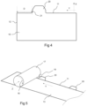
- the battery control quality process needs to precisely measure the position of each cathode tab 20 along the longitudinal edge 11 of the cathode 10. That is to say, measuring the distance D between a lateral side 21 of the cathode tab 20 and a transversal side 12 of the cathode 10.
- Said transversal side 12 of the cathode 10 is parallel to the transversal direction X and perpendicular to the longitudinal edge 11 of the cathode 10. For instance, an optical measurement system is often applied to inspect this distance D. On identifying several points on the edges 11, 20, and 21, some coordinate transformation calculations follow to get the distance D in precision at a very high speed.
- the distance D is, for instance, about 60 mm for the cathode tab 20.
- the lateral side 21 of the cathode tab 20 is not parallel to the transversal side 12 of the cathode 10, meaning that the angle between the longitudinal edge 11 and the lateral side 21 is not a right angle, then an accurate and reliable measure of the distance D will be very difficult to obtain.
- Distance D can vary depending, for instance, on the vertical position of the cathode 10, especially with rounded corners at the intersection between the cathode 10 and the cathode tab 20.
- a trapezoidal shape of the cathode tab 20, instead of a rectangular shape, would surely induce problems in measuring the distance D, and thus make the battery control quality less reliable.
- the present invention proposes a new shape for electrodes tabs which will achieve the two objectives of improving the manufacturability and productivity while maintaining a high-quality control.
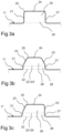
- Figure 3a shows an existing tab 20 having a classical rectangular shape. It comprises two straight parallel lateral sides 21, 21', which are parallel to the transversal direction X and perpendicular to the longitudinal edge 11 of the tab 20, and one longitudinal side 24, parallel to the longitudinal edge 11.
- the rounded corners 25 between lateral sides 21, 21' and the longitudinal side 24 are rounded with a radius for instance equal to 2 mm or even 0 mm for an easier manufacturing process, which may cause higher possibility of the "folded tab defect".
- Figure 3b discloses a first embodiment of the invention.
- the flexible tab 20 comprises two parts, a first part 28 starting from the longitudinal edge 11 of the electrode 10 extended by an adjacent second part 29.
- the first part 28 has a rectangular shape with two lateral sides 21, 21' parallel to the transversal direction X and perpendicular to the longitudinal edge 11, between two longitudinal sides 22, 22' parallel to the longitudinal edge 11. These longitudinal sides 22, 22' have the same size (not taking into account the rounded corners).
- the two lateral sides 21, 21' of the rectangle shape part 28 have for instance a length of 5 mm.
- the second part 29 of the tab 20 has a trapezoidal shape with two lateral sides 23, 23' which are inclined from the transversal direction X and not perpendicular to the longitudinal edge 11, between two longitudinal sides 24, 24', an inner longitudinal side 24' adjacent to the first part 28 of the tab 20 and an outer longitudinal side 24, which are parallel to the longitudinal edge 11.
- the two longitudinal sides 24, 24' have different sizes : the outer longitudinal side 24 of the tab 20 is smaller than the inner longitudinal side 24'.
- the sides 22' and 24' are merged. As the lateral sides 23, 23' are inclined, they come more softly into contact with a guide roll 17 during the movement of the strip 13, avoiding any backwards folding of the tab 20.
- outer round corners 25, between each lateral side 23, 23' and the outer longitudinal side 24, have a radius for instance equal to 10 mm, which is larger than the radius of the round corner 25 of Figure 3a .
- These outer round corners 25 also help the whole tab 20 enter into contact with a guided roll 17 more smoothly at contact point 19.
- the lateral side 23 (respectively 23' ) of the second part 29 of the tab 20 meets smoothly with its corresponding lateral side 21 (respectively 21' ) of the first part 28 of the tab 20, with a round corner between the lateral side 23 (respectively 23' ) of the second part 29 and its corresponding lateral side 21 (respectively 21' ) of the first part 28.
- Figure 3c discloses an alternative embodiment of the invention.
- the flexible tab 20 also comprises two parts, a first part 28 starting from the longitudinal edge 11 of the electrode 10 extended by an adjacent second part 29.
- the first part 28 has a rectangular shape and is similar to the one described above in Figure 3b .
- the second part 29 is different from the one of Figure 3b .
- the second part 29 still has a trapezoidal shape with two lateral sides 23, 23', between two longitudinal sides 24, 24' parallel to the longitudinal edge 11, having different sizes.
- only one lateral side 23 is inclined and not perpendicular to the longitudinal edge 11, while the other lateral side 23' is perpendicular to the longitudinal edge 11, and thus parallel to the lateral side 21'.
- the outer longitudinal side 24 of the tab 20 is smaller than the inner longitudinal side 24'. Similar to Figure 3b , the sides 22' and 24' are merged.
- the outer round corner 25, between the inclined lateral side 23 and the outer longitudinal side 24, has a radius for instance equal to 10 mm.
- a tab shape comprising a second trapezoidal part 29 combined with a first rectangular part 28 also gives additional benefits.
- the first rectangular part 28 of the tab 20 provides a slightly higher stiffness and a better electrical current carrying capacity (electrical conductivity) than a complete trapezoidal tab shape.
Landscapes
- Chemical & Material Sciences (AREA)
- Chemical Kinetics & Catalysis (AREA)
- Electrochemistry (AREA)
- General Chemical & Material Sciences (AREA)
- Engineering & Computer Science (AREA)
- Manufacturing & Machinery (AREA)
- Connection Of Batteries Or Terminals (AREA)
Abstract
The present invention relates to a battery cell comprising several electrodes (10, 15), each electrode (10) comprising a foil with a plane surface and a flexible tab (20) which projects beyond a longitudinal edge (11) of the foil along a vertical direction (X) perpendicular to a longitudinal direction (Y). The flexible tab (20) comprises two parts, a first part (28) starting from the longitudinal edge (11) of the foil extended by an adjacent second part (29), said first part (28) having a rectangular shape with two longitudinal sides (22, 22') of the same size and said second part (29) having a trapezoidal shape with two longitudinal sides (24, 24') of different sizes.
Description
- The present invention concerns the technical field of electric batteries, in particular lithium-ion batteries which are used, among others, to power the traction chain of electric or hybrid vehicles.
- More specifically, the invention relates to innovative electrode shapes which improve the manufacturability and the quality of a battery cell.
- Some Lithium-ion batteries comprise several battery cells, each battery cell having an electrode stack architecture comprising of a plurality of anodes (negative electrodes) and cathodes (positive electrodes), which are composed of foil and active material coating layers, stacked against each other and separated by a separation sheet (also known as a separator). Each cathode foil (also known as a current collector and made for instance with aluminium) is covered with a cathode active material coating layer and each anode foil is covered with an anode active material coating layer.
- The electrodes (i.e. cathodes and anodes) are each extended with a connecting tab consisting of a small outgrowth of foil beyond the foil plan. These tabs are flexible and are used to electrically connect all the cathodes together (and all the anodes together respectively) to external terminals of the battery to transmit the electrical energy. These tabs are usually in a small rectangle geometry with rounded corners and they extend from the longitudinal straight edge of the electrodes. All the cathode tabs are positioned at a same precise position along the longitudinal edge of the cathode. Likewise, all the anode tabs are positioned at a precise position along the longitudinal edge of the anode.
- During the manufacturing process of the battery cells, the electrodes are manufactured from long metallic strips which, after different operations, are cut to obtain each electrode sheet. During these operations, the electrode strip moves through numerous guide rolls which pass along the strip. Due to their flexibility, the tabs are often bent or tilted when passing under these guide rolls. But, when the tabs have a rectangular shape, the tabs' edges/corners have multiple chances of collision with the surface of the guide rolls with a high probability of getting "folded", instead of being merely bent during these collisions. Thus, this causes a "folded tab defect" which is a fatal failure that of course lowers the productivity of the manufacturing process. This "folding" can also occur with rectangle tabs having smaller rounded corners.
- Document
EP4123820A1 already discloses that electrode tabs can have a trapezoidal shape instead of a rectangular shape. However, for quality control issues, it is also necessary to quickly and precisely measure the longitudinal position of the tabs along the longitudinal edge of the electrodes following their assembly in an electrode stack. Such measurements are important for checking the correct positioning of all the electrodes in the stack, but they can be difficult to obtain when the electrode tabs have a trapezoidal shape. - Therefore, one purpose of the present invention is to provide an effective, reliable, economical and easy to implement solution that enhances manufacturability and productivity, while maintaining an efficient quality control of battery electrodes.
- In order to achieve the above purpose, the invention provides an electrode sheet for a battery cell, comprising a foil with a plane surface and a flexible tab which projects beyond a longitudinal edge of the foil along a transversal direction perpendicular to a longitudinal direction. That said flexible tab comprises two parts, a first part starting from the longitudinal edge of the foil extended by an adjacent second part, said first part having a rectangular shape with two longitudinal sides of the same size and said second part having a trapezoidal shape with two longitudinal sides of different sizes.
- According to one embodiment, the second part of the tab comprises an inner longitudinal side adjacent to the first part of the tab and an outer longitudinal side, the outer side being smaller than the inner side.
- According to one embodiment, the first part of the tab comprises two lateral sides which are perpendicular to the longitudinal edge of the electrode foil.
- According to one embodiment, the second part of the tab comprises two lateral sides, both of them being not perpendicular to the longitudinal edge of the foil.
- According to one embodiment, the second part of the tab comprises two lateral sides, one side being perpendicular to the longitudinal edge of the foil and the other side being not perpendicular to the longitudinal edge of the foil.
- According to one embodiment, the second part of the tab comprises two outer rounded corners.
- According to one embodiment, the lateral sides of the second part of the tab meets smoothly with their corresponding lateral sides of the first part of the tab with a filleting radius which is tangential to the lateral sides of the first part and to the lateral sides of the second part.
- The invention also provides a battery cell comprising a plurality of such electrode sheets.
- Further features and advantages of the present invention will become apparent from the following description, with reference to the annexed figures, wherein:
-
Figure 1 shows a simplified existing implementation embodiment of an electrode stack; -
Figure 2 represents a schematic perspective view of an electrode strip during the manufacturing process, with an electrode tab according to the prior art; -
Figure 3a, 3b and 3c give three examples of shapes for an electrode tab,Figure 3a showing an example according to the prior art,Figure 3b and 3c showing two examples according to the present invention; -
Figure 4 details the position of a cathode tab according to the invention; -
Figure 5 repeats the view ofFigure 2 but with an electrode tab according to the invention. - With reference to
Figure 1 , a lithium-ion battery cell comprises at least onecathode 10 in the form of a sheet, made of aluminium foil for example, coated on both sides by a cathode active material coating layer. The battery cell also comprises at least oneanode 15 in the form of a sheet, made of copper foil for example, coated on both sides by an anode active material coating layer. Theanode 15 andcathode 10 are placed against each other and are separated by aseparator 14 which can be, for instance, a thin and porous plastic film. Theanode 15 andcathode 10 are flat and have a roughly rectangular plane. - An electrode stack of a battery cell is usually composed of a stack of such electrode sheets and thus comprises a plurality of
cathodes 10 andanodes 15 which are alternately arranged and separated by a plurality ofseparators 14. InFigure 1 , only onecathode 10 oneanode 15 and oneseparator 14 are shown. - The
cathode 10 has alongitudinal edge 11 along a longitudinal direction Y and comprises aflexible tab 20 which projects beyond thelongitudinal edge 11 along a transversal direction X, which is parallel to the cathode foil plan and perpendicular to the longitudinal direction Y. Thiscathode tab 20 is only present on one section of thelongitudinal edge 11 of thecathode 10 and is, for instance, 30-50 mm wide and around 20-30 mm high. - Similarly, the
anode 15 has alongitudinal edge 16 along the longitudinal direction Y and comprises aflexible tab 30, which projects beyond thelongitudinal edge 16 along the transversal direction X. Thisanode tab 30 is only present on one section of thelongitudinal edge 16 of theanode 15 and has approximately the same dimensions as thecathode tab 20. - The
anode tab 30 is offset from thecathode tab 20 along the direction Y to avoid any contact between them in the electrode stack of the battery cell, when tabs are tilted for instance. These tabs 20 (and 30 respectively) are used to electrically connect together the electrodes 10 (and 15 respectively) to external terminals of the battery in order to transmit the electrical energy the battery cell. To facilitate these connections, thetabs - The electrodes (
anodes 15 and cathodes 10) are generally manufactured starting fromlong electrode strips 13 having flexible tabs arranged at regular intervals. Thiselectrode strip 13 undergoes different manufacturing operations, prior to being cut along the transversal direction X to obtain several electrodes of the correct dimensions. As shown inFigure 2 , during these operations theelectrode strip 13 moves along the direction Y through a path comprising many tens ofguide rolls 17 which are in arotating movement 18 according to an axis Z, parallel to the transversal direction X and perpendicular to the longitudinal direction Y. - When
tab 20 has a rectangular shape, even with rounded corners, there is a risk that, at acontact point 19 between thetab 20 and theguide roll 17, thetab 20 is not just tilted but can be folded backwards during the movement ofstrip 13. This causes a major defect and of course reduces the productivity of the manufacturing process. - According to the present invention, a trapezoidal geometry of the
tab 20 can significantly lower the probability of the tab being folded backwards during contact between thetab 20 edge/corner and the guide roll 17 surface. Such trapezoidal geometry provides higher folding resistance compared with a rectangle geometry, even with a same level of collision impact between thetab 20 and theguide roll 17. The inclined side of the trapezoid facilitates the smooth guiding of thetab 20 by enabling gradual contact between the tab edge and the guide roll 17 surface. - Furthermore, once the cathodes 10 (and respectively the anodes 15) are placed in an electrode stack, the cathode tabs 20 (and respectively the anode tabs 30) must be well aligned with each other, prior to getting assembled and welded for electrical connection of the battery cell. To verify this alignment, as shown in the example of
Figure 4 for acathode 10, the battery control quality process needs to precisely measure the position of eachcathode tab 20 along thelongitudinal edge 11 of thecathode 10. That is to say, measuring the distance D between alateral side 21 of thecathode tab 20 and atransversal side 12 of thecathode 10. Saidtransversal side 12 of thecathode 10 is parallel to the transversal direction X and perpendicular to thelongitudinal edge 11 of thecathode 10. For instance, an optical measurement system is often applied to inspect this distance D. On identifying several points on theedges cathode tab 20. - However, if the
lateral side 21 of thecathode tab 20 is not parallel to thetransversal side 12 of thecathode 10, meaning that the angle between thelongitudinal edge 11 and thelateral side 21 is not a right angle, then an accurate and reliable measure of the distance D will be very difficult to obtain. Distance D can vary depending, for instance, on the vertical position of thecathode 10, especially with rounded corners at the intersection between thecathode 10 and thecathode tab 20. A trapezoidal shape of thecathode tab 20, instead of a rectangular shape, would surely induce problems in measuring the distance D, and thus make the battery control quality less reliable. - Therefore, the present invention proposes a new shape for electrodes tabs which will achieve the two objectives of improving the manufacturability and productivity while maintaining a high-quality control.
- The three
Figures 3a, 3b and 3c show three examples of shapes for electrode tabs.Figure 3a shows an existingtab 20 having a classical rectangular shape. It comprises two straight parallellateral sides 21, 21', which are parallel to the transversal direction X and perpendicular to thelongitudinal edge 11 of thetab 20, and onelongitudinal side 24, parallel to thelongitudinal edge 11. Therounded corners 25 betweenlateral sides 21, 21' and thelongitudinal side 24 are rounded with a radius for instance equal to 2 mm or even 0 mm for an easier manufacturing process, which may cause higher possibility of the "folded tab defect". -
Figure 3b discloses a first embodiment of the invention. Theflexible tab 20 comprises two parts, afirst part 28 starting from thelongitudinal edge 11 of theelectrode 10 extended by an adjacentsecond part 29. Thefirst part 28 has a rectangular shape with twolateral sides 21, 21' parallel to the transversal direction X and perpendicular to thelongitudinal edge 11, between twolongitudinal sides 22, 22' parallel to thelongitudinal edge 11. Theselongitudinal sides 22, 22' have the same size (not taking into account the rounded corners). The twolateral sides 21, 21' of therectangle shape part 28 have for instance a length of 5 mm. - The
second part 29 of thetab 20 has a trapezoidal shape with twolateral sides 23, 23' which are inclined from the transversal direction X and not perpendicular to thelongitudinal edge 11, between twolongitudinal sides 24, 24', an inner longitudinal side 24' adjacent to thefirst part 28 of thetab 20 and an outerlongitudinal side 24, which are parallel to thelongitudinal edge 11. The twolongitudinal sides 24, 24' have different sizes : the outerlongitudinal side 24 of thetab 20 is smaller than the inner longitudinal side 24'. The sides 22' and 24' are merged. As the lateral sides 23, 23' are inclined, they come more softly into contact with aguide roll 17 during the movement of thestrip 13, avoiding any backwards folding of thetab 20. Moreover, theouter round corners 25, between eachlateral side 23, 23' and the outerlongitudinal side 24, have a radius for instance equal to 10 mm, which is larger than the radius of theround corner 25 ofFigure 3a . These outerround corners 25 also help thewhole tab 20 enter into contact with a guidedroll 17 more smoothly atcontact point 19. - Preferably, the lateral side 23 (respectively 23') of the
second part 29 of thetab 20 meets smoothly with its corresponding lateral side 21 (respectively 21') of thefirst part 28 of thetab 20, with a round corner between the lateral side 23 (respectively 23') of thesecond part 29 and its corresponding lateral side 21 (respectively 21') of thefirst part 28. -
Figure 3c discloses an alternative embodiment of the invention. In this embodiment, theflexible tab 20 also comprises two parts, afirst part 28 starting from thelongitudinal edge 11 of theelectrode 10 extended by an adjacentsecond part 29. Thefirst part 28 has a rectangular shape and is similar to the one described above inFigure 3b . Thesecond part 29 is different from the one ofFigure 3b . Thesecond part 29 still has a trapezoidal shape with twolateral sides 23, 23', between twolongitudinal sides 24, 24' parallel to thelongitudinal edge 11, having different sizes. However, only onelateral side 23 is inclined and not perpendicular to thelongitudinal edge 11, while the other lateral side 23' is perpendicular to thelongitudinal edge 11, and thus parallel to the lateral side 21'. The outerlongitudinal side 24 of thetab 20 is smaller than the inner longitudinal side 24'. Similar toFigure 3b , the sides 22' and 24' are merged. Theouter round corner 25, between the inclinedlateral side 23 and the outerlongitudinal side 24, has a radius for instance equal to 10 mm. - The alternative embodiment of
Figure 3c is suitable if, during the electrode manufacturing process, thestrip 13 always moves in the same longitudinal direction Y and always comes in contact with aguide roll 17 on thesame side 23 of all thetabs 20 of thestrip 13. In this case, the other lateral side 23' of thesecond part 29 of anytab 20 does not need to be inclined from the transversal direction X. - In addition, a tab shape comprising a second
trapezoidal part 29 combined with a firstrectangular part 28 also gives additional benefits. For instance, the firstrectangular part 28 of thetab 20 provides a slightly higher stiffness and a better electrical current carrying capacity (electrical conductivity) than a complete trapezoidal tab shape. - The scope of the present disclosure is not limited thereto, and other modifications and embodiments can be devised by those skilled in the art, without deviating from the spirit and scope of the invention described in the appended claims.
Claims (8)
- Electrode sheet for a battery cell, comprising a foil with a plane surface and a flexible tab (20) which projects beyond a longitudinal edge (11) of the foil along a transversal direction (X) perpendicular to a longitudinal direction (Y), characterized in that said flexible tab (20) comprises two parts, a first part (28) starting from the longitudinal edge (11) of the foil extended by an adjacent second part (29), said first part (28) having a rectangular shape with two longitudinal sides (22, 22') of the same size and said second part (29) having a trapezoidal shape with two longitudinal sides (24, 24') of different sizes.
- Electrode sheet according to claim 1, wherein the second part (29) of the tab (20) comprises an inner longitudinal side (24') adjacent to the first part (28) of the tab (20) and an outer longitudinal side (24), the outer side (24) being smaller than the inner side (24').
- Electrode sheet according to claim 1, wherein the first part (28) of the tab (20) comprises two lateral sides (21, 21') which are perpendicular to the longitudinal edge (11) of the electrode foil.
- Electrode sheet according to claim 3, wherein the second part (29) of the tab (20) comprises two lateral sides (23, 23'), both of them being not perpendicular to the longitudinal edge (11) of the foil.
- Electrode sheet according to claim 3, wherein the second part (29) of the tab (20) comprises two lateral sides (23, 23'), one side (23') being perpendicular to the longitudinal edge (11) of the foil and the other side (23) being not perpendicular to the longitudinal edge (11) of the foil.
- Electrode sheet according to claim 1, wherein the second part (29) of the tab (20) comprises two outer rounded corners (25).
- Electrode sheet according to claim 4 or 5, wherein the lateral side (23, 23') of the second part (29) of the tab (20) meets smoothly with the corresponding lateral side (21, 21') of the first part (28) of the tab (20), with a round corner between the lateral side (23, 23') of the second part 29 and the corresponding lateral side (21, 21') of the first part 28.
- Battery cell comprising a plurality of electrode sheets (10, 15), each electrode sheet being in accordance with one of the preceding claims.
Priority Applications (3)
| Application Number | Priority Date | Filing Date | Title |
|---|---|---|---|
| EP23305905.4A EP4475262A1 (en) | 2023-06-07 | 2023-06-07 | Tab shape for a battery electrode |
| PCT/EP2024/065509 WO2024251840A1 (en) | 2023-06-07 | 2024-06-05 | Tab shape for a battery electrode |
| DE212024000348.4U DE212024000348U1 (en) | 2023-06-07 | 2024-06-05 | Tab shape for a battery electrode |
Applications Claiming Priority (1)
| Application Number | Priority Date | Filing Date | Title |
|---|---|---|---|
| EP23305905.4A EP4475262A1 (en) | 2023-06-07 | 2023-06-07 | Tab shape for a battery electrode |
Publications (1)
| Publication Number | Publication Date |
|---|---|
| EP4475262A1 true EP4475262A1 (en) | 2024-12-11 |
Family
ID=87047780
Family Applications (1)
| Application Number | Title | Priority Date | Filing Date |
|---|---|---|---|
| EP23305905.4A Withdrawn EP4475262A1 (en) | 2023-06-07 | 2023-06-07 | Tab shape for a battery electrode |
Country Status (3)
| Country | Link |
|---|---|
| EP (1) | EP4475262A1 (en) |
| DE (1) | DE212024000348U1 (en) |
| WO (1) | WO2024251840A1 (en) |
Citations (6)
| Publication number | Priority date | Publication date | Assignee | Title |
|---|---|---|---|---|
| EP2779280A2 (en) * | 2013-03-14 | 2014-09-17 | Kabushiki Kaisha Toshiba | Battery |
| CN207441852U (en) * | 2017-11-29 | 2018-06-01 | 宁德时代新能源科技股份有限公司 | Pole piece coiled material, electrode assembly and secondary cell |
| EP3633766A1 (en) * | 2018-08-02 | 2020-04-08 | Contemporary Amperex Technology Co., Limited | Electrode member, electrode assembly, and secondary battery |
| WO2022242578A1 (en) * | 2021-05-17 | 2022-11-24 | 微宏动力系统(湖州)有限公司 | Tab plate and wound battery |
| CN115458873A (en) * | 2022-11-11 | 2022-12-09 | 深圳海润新能源科技有限公司 | Energy storage device, electric equipment and winding method |
| EP4123820A1 (en) | 2020-03-17 | 2023-01-25 | SANYO Electric Co., Ltd. | Non-aqueous electrolyte secondary battery |
-
2023
- 2023-06-07 EP EP23305905.4A patent/EP4475262A1/en not_active Withdrawn
-
2024
- 2024-06-05 WO PCT/EP2024/065509 patent/WO2024251840A1/en not_active Ceased
- 2024-06-05 DE DE212024000348.4U patent/DE212024000348U1/en active Active
Patent Citations (6)
| Publication number | Priority date | Publication date | Assignee | Title |
|---|---|---|---|---|
| EP2779280A2 (en) * | 2013-03-14 | 2014-09-17 | Kabushiki Kaisha Toshiba | Battery |
| CN207441852U (en) * | 2017-11-29 | 2018-06-01 | 宁德时代新能源科技股份有限公司 | Pole piece coiled material, electrode assembly and secondary cell |
| EP3633766A1 (en) * | 2018-08-02 | 2020-04-08 | Contemporary Amperex Technology Co., Limited | Electrode member, electrode assembly, and secondary battery |
| EP4123820A1 (en) | 2020-03-17 | 2023-01-25 | SANYO Electric Co., Ltd. | Non-aqueous electrolyte secondary battery |
| WO2022242578A1 (en) * | 2021-05-17 | 2022-11-24 | 微宏动力系统(湖州)有限公司 | Tab plate and wound battery |
| CN115458873A (en) * | 2022-11-11 | 2022-12-09 | 深圳海润新能源科技有限公司 | Energy storage device, electric equipment and winding method |
Also Published As
| Publication number | Publication date |
|---|---|
| DE212024000348U1 (en) | 2026-04-30 |
| WO2024251840A1 (en) | 2024-12-12 |
Similar Documents
| Publication | Publication Date | Title |
|---|---|---|
| US20230402722A1 (en) | Battery cell with a tabless electrode | |
| CN101485033B (en) | Electrode assembly for secondary battery with novel laminated structure | |
| US8163421B2 (en) | High durability lithium-ion cells | |
| KR101405012B1 (en) | A Stepwise Electrode Assembly Having Corner of Various Shape and a Battery Cell, Battery Pack and Device Comprising the Same | |
| US20230121494A1 (en) | Electrode assembly for battery and battery | |
| EP3840098B1 (en) | Electrode assembly and inspection method therefor | |
| EP4106035B1 (en) | Electrode assembly comprising anode and anode sheet having improved electrode stacking properties and manufacturing method therefor | |
| CN101507040A (en) | Power storage device and method for manufacturing power storage device | |
| EP4475262A1 (en) | Tab shape for a battery electrode | |
| KR20220139676A (en) | secondary battery | |
| KR20220021841A (en) | A method of manufacturing an electrode assembly comprising a anode and a anode having improved electrode stacking characteristics | |
| US20250293415A1 (en) | Battery cell and battery module | |
| US20230420809A1 (en) | Battery and battery module | |
| US20230420808A1 (en) | Battery | |
| KR102667758B1 (en) | electrode for secondary battery, electrode assembly, secondary battery and method of manufacturing electrode assembly | |
| KR102721747B1 (en) | Electrode assembly, secondary battery and method of manufacturing the same | |
| EP4560719A1 (en) | Electrode assembly and manufacturing method therefor, battery cell, battery, and electric device | |
| US20250300183A1 (en) | Electrode plate, electrode assembly and rechargeable battery including the same | |
| CN219144224U (en) | Electrode assembly, battery cell, battery and electrical device | |
| EP4654371A1 (en) | Cylindrical secondary battery and method for manufacturing cylindrical secondary battery | |
| EP4589695A2 (en) | Electrode plate, electrode assembly and rechargeable battery including the electrode assembly | |
| US11901541B2 (en) | Electrode shaping apparatus having notching pilot pin and electrode shaping method using the same | |
| US20240072376A1 (en) | Battery and method for manufacturing battery | |
| EP4556419A1 (en) | Taping device for secondary battery and secondary battery manufactured using the same | |
| US20240243251A1 (en) | Process for manufacturing a stack of electrode sheets, and cutting device, spacing element and cross-cutting device therefor |
Legal Events
| Date | Code | Title | Description |
|---|---|---|---|
| PUAI | Public reference made under article 153(3) epc to a published international application that has entered the european phase |
Free format text: ORIGINAL CODE: 0009012 |
|
| STAA | Information on the status of an ep patent application or granted ep patent |
Free format text: STATUS: THE APPLICATION HAS BEEN PUBLISHED |
|
| AK | Designated contracting states |
Kind code of ref document: A1 Designated state(s): AL AT BE BG CH CY CZ DE DK EE ES FI FR GB GR HR HU IE IS IT LI LT LU LV MC ME MK MT NL NO PL PT RO RS SE SI SK SM TR |
|
| STAA | Information on the status of an ep patent application or granted ep patent |
Free format text: STATUS: THE APPLICATION IS DEEMED TO BE WITHDRAWN |
|
| 18D | Application deemed to be withdrawn |
Effective date: 20250612 |