EP4475249A1 - Battery assembly - Google Patents
Battery assembly Download PDFInfo
- Publication number
- EP4475249A1 EP4475249A1 EP24178322.4A EP24178322A EP4475249A1 EP 4475249 A1 EP4475249 A1 EP 4475249A1 EP 24178322 A EP24178322 A EP 24178322A EP 4475249 A1 EP4475249 A1 EP 4475249A1
- Authority
- EP
- European Patent Office
- Prior art keywords
- battery cells
- battery
- accommodation
- heat transfer
- battery assembly
- Prior art date
- Legal status (The legal status is an assumption and is not a legal conclusion. Google has not performed a legal analysis and makes no representation as to the accuracy of the status listed.)
- Pending
Links
Images




Classifications
-
- H—ELECTRICITY
- H01—ELECTRIC ELEMENTS
- H01M—PROCESSES OR MEANS, e.g. BATTERIES, FOR THE DIRECT CONVERSION OF CHEMICAL ENERGY INTO ELECTRICAL ENERGY
- H01M50/00—Constructional details or processes of manufacture of the non-active parts of electrochemical cells other than fuel cells, e.g. hybrid cells
- H01M50/20—Mountings; Secondary casings or frames; Racks, modules or packs; Suspension devices; Shock absorbers; Transport or carrying devices; Holders
- H01M50/289—Mountings; Secondary casings or frames; Racks, modules or packs; Suspension devices; Shock absorbers; Transport or carrying devices; Holders characterised by spacing elements or positioning means within frames, racks or packs
- H01M50/293—Mountings; Secondary casings or frames; Racks, modules or packs; Suspension devices; Shock absorbers; Transport or carrying devices; Holders characterised by spacing elements or positioning means within frames, racks or packs characterised by the material
-
- H—ELECTRICITY
- H01—ELECTRIC ELEMENTS
- H01M—PROCESSES OR MEANS, e.g. BATTERIES, FOR THE DIRECT CONVERSION OF CHEMICAL ENERGY INTO ELECTRICAL ENERGY
- H01M10/00—Secondary cells; Manufacture thereof
- H01M10/60—Heating or cooling; Temperature control
- H01M10/65—Means for temperature control structurally associated with the cells
- H01M10/655—Solid structures for heat exchange or heat conduction
- H01M10/6554—Rods or plates
- H01M10/6555—Rods or plates arranged between the cells
-
- H—ELECTRICITY
- H01—ELECTRIC ELEMENTS
- H01M—PROCESSES OR MEANS, e.g. BATTERIES, FOR THE DIRECT CONVERSION OF CHEMICAL ENERGY INTO ELECTRICAL ENERGY
- H01M10/00—Secondary cells; Manufacture thereof
- H01M10/05—Accumulators with non-aqueous electrolyte
- H01M10/052—Li-accumulators
-
- H—ELECTRICITY
- H01—ELECTRIC ELEMENTS
- H01M—PROCESSES OR MEANS, e.g. BATTERIES, FOR THE DIRECT CONVERSION OF CHEMICAL ENERGY INTO ELECTRICAL ENERGY
- H01M10/00—Secondary cells; Manufacture thereof
- H01M10/04—Construction or manufacture in general
- H01M10/0468—Compression means for stacks of electrodes and separators
-
- H—ELECTRICITY
- H01—ELECTRIC ELEMENTS
- H01M—PROCESSES OR MEANS, e.g. BATTERIES, FOR THE DIRECT CONVERSION OF CHEMICAL ENERGY INTO ELECTRICAL ENERGY
- H01M10/00—Secondary cells; Manufacture thereof
- H01M10/60—Heating or cooling; Temperature control
- H01M10/61—Types of temperature control
- H01M10/613—Cooling or keeping cold
-
- H—ELECTRICITY
- H01—ELECTRIC ELEMENTS
- H01M—PROCESSES OR MEANS, e.g. BATTERIES, FOR THE DIRECT CONVERSION OF CHEMICAL ENERGY INTO ELECTRICAL ENERGY
- H01M10/00—Secondary cells; Manufacture thereof
- H01M10/60—Heating or cooling; Temperature control
- H01M10/65—Means for temperature control structurally associated with the cells
- H01M10/653—Means for temperature control structurally associated with the cells characterised by electrically insulating or thermally conductive materials
-
- H—ELECTRICITY
- H01—ELECTRIC ELEMENTS
- H01M—PROCESSES OR MEANS, e.g. BATTERIES, FOR THE DIRECT CONVERSION OF CHEMICAL ENERGY INTO ELECTRICAL ENERGY
- H01M10/00—Secondary cells; Manufacture thereof
- H01M10/60—Heating or cooling; Temperature control
- H01M10/65—Means for temperature control structurally associated with the cells
- H01M10/655—Solid structures for heat exchange or heat conduction
-
- H—ELECTRICITY
- H01—ELECTRIC ELEMENTS
- H01M—PROCESSES OR MEANS, e.g. BATTERIES, FOR THE DIRECT CONVERSION OF CHEMICAL ENERGY INTO ELECTRICAL ENERGY
- H01M50/00—Constructional details or processes of manufacture of the non-active parts of electrochemical cells other than fuel cells, e.g. hybrid cells
- H01M50/20—Mountings; Secondary casings or frames; Racks, modules or packs; Suspension devices; Shock absorbers; Transport or carrying devices; Holders
- H01M50/204—Racks, modules or packs for multiple batteries or multiple cells
- H01M50/207—Racks, modules or packs for multiple batteries or multiple cells characterised by their shape
- H01M50/209—Racks, modules or packs for multiple batteries or multiple cells characterised by their shape adapted for prismatic or rectangular cells
-
- H—ELECTRICITY
- H01—ELECTRIC ELEMENTS
- H01M—PROCESSES OR MEANS, e.g. BATTERIES, FOR THE DIRECT CONVERSION OF CHEMICAL ENERGY INTO ELECTRICAL ENERGY
- H01M50/00—Constructional details or processes of manufacture of the non-active parts of electrochemical cells other than fuel cells, e.g. hybrid cells
- H01M50/20—Mountings; Secondary casings or frames; Racks, modules or packs; Suspension devices; Shock absorbers; Transport or carrying devices; Holders
- H01M50/204—Racks, modules or packs for multiple batteries or multiple cells
- H01M50/207—Racks, modules or packs for multiple batteries or multiple cells characterised by their shape
- H01M50/211—Racks, modules or packs for multiple batteries or multiple cells characterised by their shape adapted for pouch cells
-
- H—ELECTRICITY
- H01—ELECTRIC ELEMENTS
- H01M—PROCESSES OR MEANS, e.g. BATTERIES, FOR THE DIRECT CONVERSION OF CHEMICAL ENERGY INTO ELECTRICAL ENERGY
- H01M50/00—Constructional details or processes of manufacture of the non-active parts of electrochemical cells other than fuel cells, e.g. hybrid cells
- H01M50/20—Mountings; Secondary casings or frames; Racks, modules or packs; Suspension devices; Shock absorbers; Transport or carrying devices; Holders
- H01M50/244—Secondary casings; Racks; Suspension devices; Carrying devices; Holders characterised by their mounting method
-
- H—ELECTRICITY
- H01—ELECTRIC ELEMENTS
- H01M—PROCESSES OR MEANS, e.g. BATTERIES, FOR THE DIRECT CONVERSION OF CHEMICAL ENERGY INTO ELECTRICAL ENERGY
- H01M50/00—Constructional details or processes of manufacture of the non-active parts of electrochemical cells other than fuel cells, e.g. hybrid cells
- H01M50/20—Mountings; Secondary casings or frames; Racks, modules or packs; Suspension devices; Shock absorbers; Transport or carrying devices; Holders
- H01M50/262—Mountings; Secondary casings or frames; Racks, modules or packs; Suspension devices; Shock absorbers; Transport or carrying devices; Holders with fastening means, e.g. locks
- H01M50/264—Mountings; Secondary casings or frames; Racks, modules or packs; Suspension devices; Shock absorbers; Transport or carrying devices; Holders with fastening means, e.g. locks for cells or batteries, e.g. straps, tie rods or peripheral frames
-
- H—ELECTRICITY
- H01—ELECTRIC ELEMENTS
- H01M—PROCESSES OR MEANS, e.g. BATTERIES, FOR THE DIRECT CONVERSION OF CHEMICAL ENERGY INTO ELECTRICAL ENERGY
- H01M50/00—Constructional details or processes of manufacture of the non-active parts of electrochemical cells other than fuel cells, e.g. hybrid cells
- H01M50/50—Current conducting connections for cells or batteries
- H01M50/502—Interconnectors for connecting terminals of adjacent batteries; Interconnectors for connecting cells outside a battery casing
-
- H—ELECTRICITY
- H01—ELECTRIC ELEMENTS
- H01M—PROCESSES OR MEANS, e.g. BATTERIES, FOR THE DIRECT CONVERSION OF CHEMICAL ENERGY INTO ELECTRICAL ENERGY
- H01M50/00—Constructional details or processes of manufacture of the non-active parts of electrochemical cells other than fuel cells, e.g. hybrid cells
- H01M50/50—Current conducting connections for cells or batteries
- H01M50/502—Interconnectors for connecting terminals of adjacent batteries; Interconnectors for connecting cells outside a battery casing
- H01M50/505—Interconnectors for connecting terminals of adjacent batteries; Interconnectors for connecting cells outside a battery casing comprising a single busbar
-
- H—ELECTRICITY
- H01—ELECTRIC ELEMENTS
- H01M—PROCESSES OR MEANS, e.g. BATTERIES, FOR THE DIRECT CONVERSION OF CHEMICAL ENERGY INTO ELECTRICAL ENERGY
- H01M50/00—Constructional details or processes of manufacture of the non-active parts of electrochemical cells other than fuel cells, e.g. hybrid cells
- H01M50/50—Current conducting connections for cells or batteries
- H01M50/572—Means for preventing undesired use or discharge
- H01M50/584—Means for preventing undesired use or discharge for preventing incorrect connections inside or outside the batteries
- H01M50/59—Means for preventing undesired use or discharge for preventing incorrect connections inside or outside the batteries characterised by the protection means
- H01M50/593—Spacers; Insulating plates
-
- H—ELECTRICITY
- H01—ELECTRIC ELEMENTS
- H01M—PROCESSES OR MEANS, e.g. BATTERIES, FOR THE DIRECT CONVERSION OF CHEMICAL ENERGY INTO ELECTRICAL ENERGY
- H01M2220/00—Batteries for particular applications
- H01M2220/20—Batteries in motive systems, e.g. vehicle, ship, plane
-
- Y—GENERAL TAGGING OF NEW TECHNOLOGICAL DEVELOPMENTS; GENERAL TAGGING OF CROSS-SECTIONAL TECHNOLOGIES SPANNING OVER SEVERAL SECTIONS OF THE IPC; TECHNICAL SUBJECTS COVERED BY FORMER USPC CROSS-REFERENCE ART COLLECTIONS [XRACs] AND DIGESTS
- Y02—TECHNOLOGIES OR APPLICATIONS FOR MITIGATION OR ADAPTATION AGAINST CLIMATE CHANGE
- Y02E—REDUCTION OF GREENHOUSE GAS [GHG] EMISSIONS, RELATED TO ENERGY GENERATION, TRANSMISSION OR DISTRIBUTION
- Y02E60/00—Enabling technologies; Technologies with a potential or indirect contribution to GHG emissions mitigation
- Y02E60/10—Energy storage using batteries
Definitions
- the present disclosure relates to a battery assembly. Specifically, the present disclosure relates to a battery assembly in which an accommodation case is spaced apart from a battery.
- Secondary batteries are batteries which are formed to convert electrical energy to chemical energy and store the chemical energy so they can be reused multiple times through charging and discharging. Secondary batteries are widely used throughout industry due to their economical and eco-friendly characteristics. Specifically, among secondary batteries, lithium secondary batteries are widely used throughout industry including portable devices that require high-density energy.
- the operating principle of the lithium secondary battery is an electrochemical oxidation-reduction reaction. That is, the operating principle is that electricity is generated by the movement of lithium ions and charging is performed through the reverse process.
- a process, in which the lithium ions exit the anode and move to the cathode through an electrolyte and a separator is referred to as discharging.
- a reverse process with respect to this process is referred to as charging.
- a secondary battery may generate a large amount of heat in the charging and discharging process. When the heat generated in the secondary battery is not suppressed quickly, a fire can propagate to adjacent battery cells to cause significant damage.
- the present disclosure is directed to preventing damage to a battery assembly by applying uniform surface pressure to a battery cell.
- the present disclosure is also directed to improving the stability of a battery assembly by uniformly managing a temperature rise and suppressing an excessive temperature rise of a battery cell.
- the present disclosure is also directed to improving the structural stability of a battery assembly and preventing damage due to external pressure by minimizing the deviation of a battery cell from a preset position.
- the present disclosure may be widely applied to green technology fields such as electric vehicles and battery charging stations in addition to solar power generation and wind power generation that use batteries.
- the present disclosure can be used for eco-friendly electric vehicles, hybrid vehicles, and the like to prevent climate change by suppressing air pollution and greenhouse gas emission.
- a battery assembly including a plurality of battery cells stacked in a preset stacking direction, an accommodation case which accommodates the plurality of battery cells therein, and one or more heat transfer parts which are located between the plurality of battery cells and in contact with a first surface and a second surface opposite to the first surface of the accommodation case, wherein the plurality of battery cells are positioned to be spaced apart from the first surface and the second surface.
- the accommodation case may further include an accommodation body which includes the first surface and forms an accommodation space and an accommodation cover which covers the accommodation body and includes the second surface.
- the accommodation case may further include a side body which connects the first surface and the second surface and presses the plurality of battery cells.
- the side body may include a facing surface facing the plurality of battery cells, and the facing surface may be inclined.
- the accommodation case may further include an opening, which is an open surface, and the side body may be inclined toward the plurality of battery cells as a distance from the opening increases.
- the battery assembly may further include a pressing part which is located between the side body and the plurality of battery cells and presses the plurality of battery cells.
- the heat transfer part may be located between cell groups each grouped into a preset number of battery cells among the plurality of battery cells.
- the battery assembly may further include a coupling part which couples a battery cell adjacent to the heat transfer part among the plurality of battery cells and the heat transfer part.
- a length of the heat transfer part in a direction from the first surface toward the second surface may be greater than or equal to a length of the plurality of battery cells.
- the battery assembly may further include a busbar assembly which electrically connects the plurality of battery cells.
- the busbar assembly may include a busbar in contact with the plurality of battery cells and a busbar frame which is electrically insulated from the busbar, couples the busbar to the accommodation case, and is provided with a through hole.
- the battery assembly may further include a filler which is provided in the accommodation case and in contact with at least portions of the plurality of battery cells.
- the filler may be formed of an insulating material.
- the filler may be formed of a coolant for decreasing a temperature of the plurality of battery cells.
- the heat transfer part may include a main body in contact with the plurality of battery cells and a contact portion which extends from each of both ends of the main body, is in contact with the accommodation case, and is formed in a circular or polygonal shape.
- the accommodation case may include a recessed portion which is formed by recessing one region of the accommodation case and in which each of the one or more heat transfer parts is located.
- the recessed portion may extend in a direction from the first surface toward the second surface and in a direction perpendicular to the stacking direction.
- the heat transfer part may move a preset moving distance or less in the stacking direction due to the recessed portion.
- a description representing a relative or absolute arrangement such as “face a direction,” “in a direction,” “side by side,” “vertically,” “centered,” “concentric,” or “coaxial,” not only represents such an exact arrangement but also represents a state in which there is a relative displacement having a tolerance or an angle or distance with which the same function is obtained.
- Each axis direction means both directions in which each axis extends.
- first, second, or third added in front of components mentioned below is only for avoiding confusion about the indicated components and is irrelevant to the order, importance, or main-subordinate relationship between the components.
- a disclosure including only a second component may be implemented without a first component.
- FIG. 1 is a view illustrating a battery cell 10 according to the present disclosure.
- the battery cell 10 described in the present specification is a secondary battery that can be repeatedly reused by charging and discharging electrical energy.
- the battery cell 10 may be a lithium secondary battery but is not limited thereto.
- the battery cell 10 may be classified into a pouch-type secondary battery, a prismatic secondary battery, or a cylindrical secondary battery according to a shape thereof.
- a pouch-type secondary battery a prismatic secondary battery, or a cylindrical secondary battery according to a shape thereof.
- an example of the pouch-type secondary battery will be described for the sake of convenience in the description, but the present disclosure is not limited thereto.
- the battery cell 10 includes an electrode assembly (not shown).
- the electrode assembly may include a cathode, an anode, and a separator.
- the electrode assembly may be classified into a stacking, winding, stack-folding, or Z-stacking type electrode assembly according to a method of stacking the cathode, anode, and separator.
- Each of the cathode and the anode may include a current collector.
- the cathode may include a cathode current collector, and the anode may include an anode current collector.
- the current collector may include a known conductive material to the extent that it does not cause a chemical reaction in the lithium secondary battery.
- the current collector may include any one of stainless steel, nickel (Ni), aluminum (Al), titanium (Ti), copper (Cu), and alloys thereof and may be provided in various forms such as a film, sheet, or foil.
- Each of the cathode and the anode may include an active material.
- the cathode may include a cathode active material
- the anode may include an anode active material.
- the cathode active material may be a material into which lithium ions may be intercalated and from which the lithium ions may be deintercalated
- the anode active material may be a material in which lithium ions may be intercalated and from which the lithium ions may be deintercalated.
- the cathode active material may be a lithium metal oxide
- the anode active material may be any one among a carbon-based material such as crystalline carbon, amorphous carbon, a carbon composite, and carbon fiber, a lithium alloy, silicon (Si), and tin (Sn).
- the cathode and the anode may further include a binder and a conductive material for improving mechanical stability and electrical conductivity, respectively.
- the separator may be formed to prevent an electrical short circuit between the cathode and the anode and allow ions to flow.
- the type of separator is not particularly limited and may include a porous polymer film.
- the separator may include a porous polymer film or a porous polymer non-woven fabric.
- the electrolyte may include an electrolyte solution.
- the electrolyte solution may be a non-aqueous electrolyte solution.
- the electrolyte solution may include a lithium salt and an organic solvent.
- the electrolyte solution may further include an additive.
- the additive may form a film on the cathode or the anode through a chemical reaction in the battery. For example, a cathode interfacial film may be formed on the cathode, and an anode interfacial film may be formed on the anode.
- the battery cell 10 may further include an exterior material 12 which accommodates the electrode assembly therein.
- the exterior material 12 may accommodate the electrode assembly and electrolyte solution therein.
- the exterior material 12 may include an outer insulation layer and an inner adhesive layer each formed of a polymer material and include a metal layer interposed between the outer insulation layer and the inner adhesive layer.
- the exterior material 12 may include a material with high mechanical rigidity for protecting the battery cell 10 from external impacts. For example, a case may include an aluminum layer.
- the battery cell 10 may further include an electrode lead 11 protruding outward from the exterior material 12.
- the electrode lead 11 may be connected to each of the cathode and anode of the battery cell 10.
- the electrode lead 11 may include a cathode lead 11a connected to the cathode and an anode lead 11b connected to the anode.
- FIGS. 2 and 3 are views illustrating a battery assembly 100 according to the present disclosure.
- the battery assembly 100 of the present disclosure includes a plurality of battery cells 10, an accommodation case 110, and heat transfer parts 200.
- the heat transfer parts 200 are located between the plurality of battery cells 10 to come into contact a first surface 110a and a second surface 110b opposite to the first surface 110a of the accommodation case 110.
- the plurality of battery cells 10 are positioned to be spaced apart from the first surface 110a and the second surface 110b.
- the battery assembly 100 of the present disclosure may include a battery module or battery pack.
- the battery module is a module in which one or more battery cells 10 are grouped and accommodated in a case to protect the battery cells 10 from external impacts, heat, vibrations, and the like and have high output and capacity characteristics.
- the battery pack is a pack in which one or more battery cells 10 or battery modules are grouped.
- the battery assembly 100 may be formed in a cell-to-pack structure in which the battery cells 10 are directly accommodated in a pack case.
- the accommodation case 110 may be a module case.
- the accommodation case 110 may be a pack case.
- the plurality of battery cells 10 may be stacked in a preset stacking direction.
- the plurality of battery cells 10 may be stacked in a Y-direction.
- the accommodation case 110 may accommodated the plurality of battery cells 10 therein.
- the accommodation case 110 may include an accommodation space for accommodating the plurality of battery cells 10.
- the accommodation case 110 may be provided as a hexahedron. Accordingly, the battery assembly 100 may be effectively stacked.
- the accommodation case 110 includes the first surface 110a and the second surface 110b. Each of the first surface 110a and the second surface 110b may form one side surface of the accommodation space.
- the first surface 110a and the second surface 110b may be provided to face each other.
- the first surface 110a may be a bottom surface
- the second surface 110b may be an upper surface.
- the accommodation case 110 may include an accommodation body 120 and an accommodation cover 130.
- the accommodation body 120 and the accommodation cover 130 may be combined to form the accommodation case 110.
- the accommodation body 120 may include the first surface 110a and form the accommodation space.
- the plurality of battery cells 10 may be located in the accommodation body 120.
- the first surface 110a may be one surface provided inside the accommodation body 120.
- the accommodation body 120 may include a lower body 121.
- the plurality of battery cells 10 may be located on the lower body 121.
- a plurality of battery cells 10 may be stacked and positioned on the lower body 121 in the stacking direction.
- the lower body 121 may be provided in parallel to the stacking direction.
- a surface facing the plurality of battery cells 10 may be the first surface 110a.
- the accommodation cover 130 may cover the accommodation body 120.
- the accommodation cover 130 may include the second surface 11 0b.
- the second surface 110b may be one surface provided inside the accommodation cover 130.
- the accommodation case 110 may further include an opening 110c which is an open surface.
- One surface of the accommodation body 120 may be open.
- the plurality of battery cells 10 may be inserted through the opening 110c.
- the accommodation body 120 may have a rectangular parallelepiped shape with one open surface. A plurality of battery cells 10 may be inserted through the opening 110c.
- the accommodation cover 130 may cover the opening. In other words, the accommodation cover 130 may close one surface of the accommodation body 120 to seal the internal accommodation space.
- the accommodation case 110 may further include an injection hole 131.
- the injection hole 131 may be formed by passing through one region of the accommodation case 110.
- the injection hole 131 may be provided in the accommodation cover 130.
- a filler 500 may be injected into the accommodation case 110 through the injection hole. After the accommodation body 120 and the accommodation cover 130 are combined, the filler 500 may be injected through the injection hole 131. In another embodiment, after a plurality of battery cells are inserted through the opening 110c of the accommodation body 120, a filler 500 may be injected, and an accommodation cover 130 may be coupled to the accommodation body 120.
- the accommodation case 110 further includes a side body 140.
- the side body 140 may connect the first surface 110a and the second surface 110b to press the plurality of battery cells 10.
- the accommodation body 120 may include the side body 140.
- the side body 140 may be formed to extend from a corner of the lower body 121. As a result, the side body 140 may connect the lower body 121 and the accommodation cover 130.
- the side body 140 may press the plurality of battery cells 10.
- the side body 140 may press a battery cell 10 provided at an outermost side among the plurality of battery cells 10 in the stacking direction.
- the plurality of battery cells 10 may be suppressed from moving by being pressed by the side body 140.
- the plurality of battery cells 10 may be pressed by the side body 140 in the Y-direction. Accordingly, the movement of the battery cell 10a in a Z-direction may be prevented, and a state in which the battery cells 10 are spaced apart from the first surface 110a and the second surface 110b of the accommodation case 110 may be maintained.
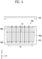
- FIG. 4 is a view illustrating a battery assembly 100 according to another embodiment of the present disclosure.
- a side body 140 may include a facing surface 140a facing a plurality of battery cells 10.
- the side body 140 may include the facing surface 140a facing a battery cell 10 provided at an outermost side among the plurality of battery cells 10 in a stacking direction.
- the facing surface 140a may be provided on the inner side of the side body 140 in a Y-direction.
- the facing surface 140a may be provided to be inclined. This is to easily and effectively fix the battery cells 10 after the plurality of battery cells 10 are accommodated in an accommodation case 110.
- a width of the side body 140 should be approximately equal to a length of the plurality of battery cells 10. However, for the plurality of battery cells 10 to be inserted through an opening 110c, the width of the side body 140 should be greater than the length of the plurality of battery cells 10.
- the side body 140 may be provided in a structure in which the width of the side body 140 in the stacking direction decreases as the distance from the opening 110c increases.
- the side body 140 may be provided to be inclined toward the plurality of battery cell as the distance from the opening 110c increases.
- the plurality of battery cells 10 may be inserted through the opening 110c.
- the plurality of battery cells 10 may come into contact with an inclined surface.
- the plurality of battery cells 10 may not come into contact with a lower surface of an accommodation body 120.
- the width of the side body 140 in the Y-direction may decrease toward the bottom in a Z-direction.
- An upper width L3 of the side body 140 may be greater than a lower width L4 of the side body 140.
- the battery assembly 100 of the present disclosure may further include a pressing part 600.
- the pressing part 600 may be located between the side body 140 and the plurality of battery cells 10.
- the pressing part 600 may press the plurality of battery cells 10.
- the pressing part 600 may be positioned between the inclined surface of the side body 140 and the plurality of battery cells 10.
- the width of the side body 140 is variable, the plurality of battery cells 10 may not be pressed uniformly.
- One surface of the pressing part 600 may be provided to correspond to a shape of the side body 140.
- the other surface of the pressing part 600 may be provided in a flat shape to uniformly press the battery cells 10. Accordingly, the pressing part 600 may uniformly press the plurality of battery cells 10. In addition, the movement of the plurality of battery cells 10 can be prevented.
- the pressing part 600 may include a plastic resin.
- the pressing part 600 may include a polypropylene resin or modified polyphenylene oxide (MPPO) resin. Accordingly, the pressing part 600 may be formed to correspond to a shape of the accommodation case 110 through high moldability. In addition, the pressing part 600 can withstand strong impacts and have superior heat resistance and high electrical insulation properties.
- MPPO modified polyphenylene oxide
- one surface of the pressing part 600 may be provided to be inclined.
- the other surface of the pressing part 600 may be provided to be flat to uniformly press the battery cells 10. Accordingly, damage to the battery cells 10 can be prevented.
- one surface of the accommodation case 110 may include a heat sink and a thermal interface to perform indirect water cooling.
- the thermal interface may be provided as an adhesive of pad. That is, one side surface of the battery cell 10 may be fixedly coupled to the thermal interface.
- the battery cell 10 When cell swelling occurs as the battery cell 10 is repeatedly charged and discharged, the battery cell 10 swells in a state in which one side surface of the battery cell 10 is fixed, and thus a non-uniform surface pressure may be applied to the cell. Accordingly, the performance of the battery assembly 100 may be degraded due to tearing of the battery cell 10 or lithium (Li)-plating.
- the battery assembly 100 of the present disclosure may further include heat transfer parts 200.
- the plurality of battery cells 10 may be present in a state of being spaced apart from the accommodation case 110 due to the heat transfer parts 200.
- the heat transfer parts 200 may be located between the plurality of battery cells 10.
- the heat transfer parts 200 may be located between the plurality of battery cells 10 in the stacking direction. In other words, the heat transfer parts 200 may be stacked with the plurality of battery cells 10 in the stacking direction.
- Each of the heat transfer parts 200 may be provided as a board or plate with a small thickness.
- the thickness of the heat transfer part 200 in the stacking direction may be smaller than a thickness of the battery cell 10. This is to avoid lowering the energy density of the battery assembly and to minimize the volume occupied by the heat transfer parts 200 and to include a large number of battery cells 10.
- the heat transfer parts 200 may be located between cell groups each grouped into a preset number of battery cells 10 among the plurality of battery cells 10.
- the preset number may be changed to correspond to the set specifications of the battery assembly 100.
- one heat transfer part 200 and one battery cell 10 may be alternately disposed.
- the preset number is two, a structure in which two battery cells 10 and one heat transfer part 200 are stacked may be repeated.
- the heat transfer part 200 may cool adjacent cells.
- the heat transfer part 200 may have high thermal conductivity.
- the heat transfer parts 200 may be disposed between the plurality of battery cells and effectively decrease the temperature of the battery cells. Accordingly, the thermal stability of the battery assembly 100 can be improved.
- the heat transfer part may be formed of a material with a thermal conductivity of 15 W/m ⁇ K or more.
- the heat transfer part may include copper with a thermal conductivity of about 400 W/m ⁇ K, aluminum with a thermal conductivity of about 200 W/m ⁇ K, or stainless steel with a thermal conductivity of 15 W/m. K.
- the heat transfer part may include SUS304 stainless steel.
- the stability and cooling efficiency of the battery cells 10 can be increased. Conversely, when a small number of heat transfer parts 200 are included, the stability of the battery cells 10 may be relatively lowered, but the energy density thereof may increase.
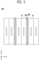
- FIG. 5 is a view illustrating coupling parts 300 according to the present disclosure.
- the battery assembly 100 of the present disclosure may further include coupling parts 300.
- the coupling parts 300 may couple the battery cells 10 and the heat transfer parts 200.
- the coupling parts 300 may couple the battery cells 10 adjacent to the heat transfer parts 200 and the heat transfer parts 200.
- Each of the coupling parts 300 may include an adhesive material.
- the coupling part 300 may be located between the battery cell 10 and the heat transfer part 200 to couple the battery cell 10 and the heat transfer part 200.
- the coupling part 300 may be a double-sided tape or hot melt adhesive.
- the heat transfer parts 200 may be in contact with each of the first surface 110a and the second surface 110b of the accommodation case 110.
- the heat transfer parts 200 may be coupled to the plurality of battery cells 10, and the plurality of battery cells 10 may be positioned to be spaced apart from the first surface 110a and the second surface 110b of the accommodation case 110.
- a length L1 of the heat transfer part 200 may be greater than or equal to a length L2 of the plurality of battery cells in a direction from the first surface 110a toward the second surface 110b.
- the plurality of battery cells 10 may be pressed by the side body 140, positions thereof may be fixed, a state in which the plurality of battery cells 10 are spaced apart from the first surface 110a and the second surface 110b may be maintained.
- a flow path may be formed between the first surface 110a and the plurality of battery cells 10 and between the second surface 110b and the plurality of battery cells 10.
- a gas or liquid may flow through the flow path.
- the battery assembly 100 of the present disclosure may further include a filler 500.
- the filler 500 may be provided in the accommodation case 110 and may come into contact with at least portions of the plurality of battery cells 10.
- the filler 500 may be injected through the opening 110c of the accommodation case 110.
- the filler 500 may be injected through the injection hole 131 of the accommodation case 110.
- the filler 500 may be formed of an insulating material.
- the filler 500 may have characteristics such as a high dielectric breakdown voltage, a low transfer factor, high specific heat, and high thermal conductivity.
- the stability of the filler 500 may be maintained in terms of insulation properties despite external physical and chemical changes. Accordingly, the filler 500 may have superior insulation performance, and the battery cells 10 may be immersed therein, and thus the battery cells 10 can be cooled.
- the filler 500 may include transformer oil.
- Transformer oil is oil which is stable at high temperatures and has high insulation properties.
- the battery cells 10 may be maintained in an insulated state while the battery cells 10 are cooled through the transformer oil.
- the transformer oil may include any one or more among mineral oil, synthetic oil, alkyl benzene, polychlorinated biphenyl (PCB), mixed oil, and a high molecular weight hydrocarbon (R-TEMP).
- PCB polychlorinated biphenyl
- R-TEMP high molecular weight hydrocarbon
- Mineral oil-based transformer oil may include naphthenic hydrocarbons, paraffinic hydrocarbons, aromatic hydrocarbons, etc.
- Synthetic oil may mean that the properties of mineral oil have been adjusted through a chemical synthesis reaction.
- alkyl benzene may have superior electrical properties and oxidation stability, and thus may be mixed with mineral oil-based transformer oil and used.
- PCB may have better electrical and chemical properties than general mineral oil.
- PCB is flame-retardant and has a large heat capacity and superior electrical insulation properties.
- PCB may be chemically stable, have acid and alkali resistance properties, may be extremely soluble in water, and may not be soluble in an organic solvent.
- R-TEMP is a type of flame-retardant transformer oil with higher flash and combustion points than mineral oil, making it highly fire-resistant and having a high dielectric breakdown voltage.
- the filler 500 may be formed of a coolant.
- the filler 500 may include a coolant to decrease the temperature of the plurality of battery cells. As described above, since the heat transfer part 200 includes a material with high thermal conductivity, and the filler is provided as a coolant, the temperature of the battery assembly 100 can be kept low.
- FIG. 6 is a view illustrating a busbar assembly 400 according to the present disclosure.
- the battery assembly 100 of the present disclosure may further include the busbar assembly 400.
- the busbar assembly 400 may electrically connect the plurality of battery cells 10.
- the busbar assembly 400 may include a busbar 410 and a busbar frame 420.
- the busbar 410 may be in contact with the plurality of battery cells 10. Specifically, the busbar 410 may be in contact with the electrode lead 11 of the battery cell 10. Accordingly, the busbar 410 may electrically connect the battery cell 10 and an external device.
- the busbar 410 may be formed of a conductive material and include a slit 411 into which the electrode lead 11 is inserted. After the electrode lead 11 is inserted into the slit 411, the electrode lead 11 may be partially bonded to the busbar 410 so that the battery cell 10 may be electrically connected to the busbar 410.
- the slit 411 may be a through hole passing through one region of the busbar 410. Without being limited thereto, the slit 411 may include an open side surface, and the electrode lead 11 may inserted through the open side surface.
- the busbar frame 420 may be electrically insulated from the busbar 410 and coupled to the accommodation case 110.
- the busbar frame 420 may include a plastic resin.
- the busbar frame 420 may be located between the busbar 410 and the battery cell 10. Accordingly, the busbar frame 420 may prevent the busbar 410 from coming into contact with regions of the battery cell 10 other than the electrode lead 11.
- the busbar frame 420 may be coupled to the accommodation case 110.
- the busbar frame 420 may be coupled to the accommodation case 110 by bolting, riveting, or bonding.
- the busbar frame 420 may include a through hole 421.
- the filler 500 may move through the through hole 421.
- the through hole 421 may be a flow path through which transformer oil moves.
- FIG. 7 is an enlarged view illustrating region A of FIG. 2 .
- the heat transfer part 200 may move according to changes in the battery cell 10.
- the heat transfer part 200 may move while in contact with the accommodation case 110.
- the heat transfer part 200 may slidably move while in contact with the first surface 110a and the second surface 110b of the accommodation case 110. Accordingly, the heat transfer part 200 may maintain the stability of the battery assembly by flexibly responding to changes in the volume of the battery cell.
- the cell group may be provided between two heat transfer parts 200.
- the heat transfer parts 200 may move in directions away from each other.
- the heat transfer parts 200 may come into contact with wide areas of the battery cells 10 to uniformly transmit pressure thereto.
- FIG. 8A and FIG. 8B are a set of views each illustrating heat transfer parts 200 according to another embodiment of the present disclosure.
- Each of the heat transfer parts 200 may include a main body 210 and a contact portion 220.
- the main body 210 may be in contact with a plurality of battery cells 10.
- One surface of the battery cell 10 may be provided to be flat for ease of stacking. Adjacent battery cells 10 may come into contact with each other through one surfaces provided to be flat to maximize spatial efficiency.
- the main body 210 may be in contact with a flat surface of the battery cell 10.
- One surface of the main body 210 may be in contact with any one battery cell 10, and the other surface of the main body 210 may be in contact with another battery cell 10.
- the entire surface of the battery cell 10 may be in contact with the main body 210.
- an area of the main body 210 may be greater than or equal to an area of the battery cell 10.
- the heat transfer part 200 may include contact portions 220 which extend from both ends of the main body 210 and come into contact with an accommodation case 110.
- the contact portions 220 may be provided on both ends of the main body 210. An area of each of the contact portions 220 in contact with the accommodation case needs to be minimized so that the contact portion 220 moves while being in contact with the accommodation case 110.
- the contact portion 220 may be provided in a circular or polygonal shape.
- the heat transfer part 200 may be stably supported between a first surface 110a and a second surface 110b of the accommodation case 110 and also easily move due to a low frictional force.
- the contact portion 220 is not limited to the circular or polygonal shape and may be provided in any shape minimizing a contact area.
- FIG. 9 is a view illustrating an accommodation case according to another embodiment of the present disclosure.
- An accommodation case 110 may further include recessed portions 150.
- the recessed portion 150 may be formed by recessing one region of the accommodation case 110.
- At least one heat transfer part 200 may be located in each of the recessed portions 150.
- the number of recessed portions 150 may correspond to the number of heat transfer parts 200.
- the recessed portions 150 may be provided in regions corresponding to the heat transfer parts 200 and the accommodation case 110.
- Each of the recessed portions 150 may extend in a direction from a first surface 110a toward a second surface 110b and in a direction perpendicular to a stacking direction.
- the recessed portion 150 may extend in an X-direction. This is because the heat transfer part 200 is provided with a flat surface perpendicular to a Y-direction.
- the recessed portion 150 should extend in the X-direction.
- the movement of the heat transfer part 200 may be restricted by the recessed portion 150.
- the recessed portion 150 allows the heat transfer part 200 to move preset moving distance or less in the stacking direction.
- the preset distance may be smaller than or equal to a length of the recessed portion 150.
- the battery cell 10 may swell to move the heat transfer part 200 in the Y-direction.
- the movement of the heat transfer part 200 may be restricted by the recessed portion 150.
- the moving distance of the heat transfer part 200 may be smaller than the length of the recessed portion 150 in the Y-direction. Accordingly, the battery cell 10 may be prevented from deviating from its designated position to stably maintain the center of gravity of the battery cell 10, and thus damage to the battery assembly 100 can be prevented.
- damage to a battery assembly can be prevented by applying uniform surface pressure to a battery cell.
- the stability of a battery assembly can be improved by uniformly managing a temperature rise and suppressing an excessive temperature rise of a battery cell.
- the structural stability of a battery assembly can be improved and the damage due to external pressure can be prevented by minimizing the deviation of a battery cell from a preset position.
Landscapes
- Chemical & Material Sciences (AREA)
- Chemical Kinetics & Catalysis (AREA)
- Electrochemistry (AREA)
- General Chemical & Material Sciences (AREA)
- Engineering & Computer Science (AREA)
- Manufacturing & Machinery (AREA)
- Battery Mounting, Suspending (AREA)
- Secondary Cells (AREA)
Abstract
A battery assembly of the present disclosure may include a plurality of battery cells stacked in a preset stacking direction, an accommodation case which accommodates the plurality of battery cells therein, and one or more heat transfer parts which are located between the plurality of battery cells and in contact with a first surface and a second surface opposite to the first surface of the accommodation case, wherein the plurality of battery cells may be positioned to be spaced apart from the first surface and the second surface.
Description
- The present disclosure relates to a battery assembly. Specifically, the present disclosure relates to a battery assembly in which an accommodation case is spaced apart from a battery.
- Secondary batteries are batteries which are formed to convert electrical energy to chemical energy and store the chemical energy so they can be reused multiple times through charging and discharging. Secondary batteries are widely used throughout industry due to their economical and eco-friendly characteristics. Specifically, among secondary batteries, lithium secondary batteries are widely used throughout industry including portable devices that require high-density energy.
- The operating principle of the lithium secondary battery is an electrochemical oxidation-reduction reaction. That is, the operating principle is that electricity is generated by the movement of lithium ions and charging is performed through the reverse process. In the case of lithium secondary batteries, a process, in which the lithium ions exit the anode and move to the cathode through an electrolyte and a separator, is referred to as discharging. In addition, a reverse process with respect to this process is referred to as charging.
- A secondary battery may generate a large amount of heat in the charging and discharging process. When the heat generated in the secondary battery is not suppressed quickly, a fire can propagate to adjacent battery cells to cause significant damage.
- In addition, when charging and discharging are repeated, swelling can occur, which applies unexpected pressure to adjacent battery cells and thus significant damage may occur.
- Accordingly, suppressing the temperature rise occurring when a secondary battery is used and suppressing damage due to pressure are emerging as major challenges.
- The present disclosure is directed to preventing damage to a battery assembly by applying uniform surface pressure to a battery cell.
- The present disclosure is also directed to improving the stability of a battery assembly by uniformly managing a temperature rise and suppressing an excessive temperature rise of a battery cell.
- The present disclosure is also directed to improving the structural stability of a battery assembly and preventing damage due to external pressure by minimizing the deviation of a battery cell from a preset position.
- The present disclosure may be widely applied to green technology fields such as electric vehicles and battery charging stations in addition to solar power generation and wind power generation that use batteries. In addition, the present disclosure can be used for eco-friendly electric vehicles, hybrid vehicles, and the like to prevent climate change by suppressing air pollution and greenhouse gas emission.
- According to an aspect of the present disclosure, there is provided a battery assembly including a plurality of battery cells stacked in a preset stacking direction, an accommodation case which accommodates the plurality of battery cells therein, and one or more heat transfer parts which are located between the plurality of battery cells and in contact with a first surface and a second surface opposite to the first surface of the accommodation case, wherein the plurality of battery cells are positioned to be spaced apart from the first surface and the second surface.
- The accommodation case may further include an accommodation body which includes the first surface and forms an accommodation space and an accommodation cover which covers the accommodation body and includes the second surface.
- The accommodation case may further include a side body which connects the first surface and the second surface and presses the plurality of battery cells.
- The side body may include a facing surface facing the plurality of battery cells, and the facing surface may be inclined.
- The accommodation case may further include an opening, which is an open surface, and the side body may be inclined toward the plurality of battery cells as a distance from the opening increases.
- The battery assembly may further include a pressing part which is located between the side body and the plurality of battery cells and presses the plurality of battery cells.
- The heat transfer part may be located between cell groups each grouped into a preset number of battery cells among the plurality of battery cells.
- The battery assembly may further include a coupling part which couples a battery cell adjacent to the heat transfer part among the plurality of battery cells and the heat transfer part.
- A length of the heat transfer part in a direction from the first surface toward the second surface may be greater than or equal to a length of the plurality of battery cells.
- The battery assembly may further include a busbar assembly which electrically connects the plurality of battery cells.
- The busbar assembly may include a busbar in contact with the plurality of battery cells and a busbar frame which is electrically insulated from the busbar, couples the busbar to the accommodation case, and is provided with a through hole.
- The battery assembly may further include a filler which is provided in the accommodation case and in contact with at least portions of the plurality of battery cells.
- The filler may be formed of an insulating material.
- The filler may be formed of a coolant for decreasing a temperature of the plurality of battery cells.
- The heat transfer part may include a main body in contact with the plurality of battery cells and a contact portion which extends from each of both ends of the main body, is in contact with the accommodation case, and is formed in a circular or polygonal shape.
- The accommodation case may include a recessed portion which is formed by recessing one region of the accommodation case and in which each of the one or more heat transfer parts is located.
- The recessed portion may extend in a direction from the first surface toward the second surface and in a direction perpendicular to the stacking direction.
- The heat transfer part may move a preset moving distance or less in the stacking direction due to the recessed portion.
- The above and other objects, features and advantages of the present disclosure will become more apparent to those of ordinary skill in the art by describing exemplary embodiments thereof in detail with reference to the accompanying drawings, in which:
-
FIG. 1 is a view illustrating a battery cell according to the present disclosure; -
FIGS. 2 and3 are views illustrating a battery assembly according to the present disclosure; -
FIG. 4 is a view illustrating a battery assembly according to another embodiment of the present disclosure; -
FIG. 5 is a view illustrating coupling parts according to the present disclosure; -
FIG. 6 is a view illustrating a busbar assembly according to the present disclosure; -
FIG. 7 is an enlarged view illustrating region A ofFIG. 2 ; -
FIG. 8A and FIG. 8B are a set of views each illustrating heat transfer parts according to another embodiment of the present disclosure; and -
FIG. 9 is a view illustrating an accommodation case according to another embodiment of the present disclosure. - Hereinafter, exemplary embodiments of the present disclosure will be described in detail with reference to the accompanying drawings. The configurations or control methods of apparatuses which will be described below are only for describing the embodiments of the present disclosure and not for limiting the scope of the present disclosure, and like reference numerals refer to like elements throughout the specification.
- Specific terms used in the present specification are only for the sake of convenience in the description and are not used to limit the embodiments.
- For example, a description such as "same" and "is the same as" not only indicates exactly the same state but also indicates a state in which there is a tolerance or difference with which the same function is obtained.
- For example, a description representing a relative or absolute arrangement such as "face a direction," "in a direction," "side by side," "vertically," "centered," "concentric," or "coaxial," not only represents such an exact arrangement but also represents a state in which there is a relative displacement having a tolerance or an angle or distance with which the same function is obtained.
- In order to describe the present disclosure, a description will be performed below based on a spatial orthogonal coordinate system with an X-axis, a Y-axis, and a Z-axis perpendicular to each other. Each axis direction (X-axis direction, Y-axis direction, and Z-axis direction) means both directions in which each axis extends.
- The X-direction, Y-direction, and Z-direction mentioned below are for describing the present disclosure so that the present disclosure can be clearly understood, and each direction can be defined differently depending on a reference.
- The use of terms such as "first, second, or third" added in front of components mentioned below is only for avoiding confusion about the indicated components and is irrelevant to the order, importance, or main-subordinate relationship between the components. For example, a disclosure including only a second component may be implemented without a first component.
- The singular forms used in the present specification are intended to include the plural forms as well, unless the context clearly indicates otherwise.
-
FIG. 1 is a view illustrating abattery cell 10 according to the present disclosure. - The
battery cell 10 described in the present specification is a secondary battery that can be repeatedly reused by charging and discharging electrical energy. For example, thebattery cell 10 may be a lithium secondary battery but is not limited thereto. - The
battery cell 10 may be classified into a pouch-type secondary battery, a prismatic secondary battery, or a cylindrical secondary battery according to a shape thereof. In the present specification, an example of the pouch-type secondary battery will be described for the sake of convenience in the description, but the present disclosure is not limited thereto. - The
battery cell 10 includes an electrode assembly (not shown). The electrode assembly may include a cathode, an anode, and a separator. The electrode assembly may be classified into a stacking, winding, stack-folding, or Z-stacking type electrode assembly according to a method of stacking the cathode, anode, and separator. - Each of the cathode and the anode may include a current collector. The cathode may include a cathode current collector, and the anode may include an anode current collector. The current collector may include a known conductive material to the extent that it does not cause a chemical reaction in the lithium secondary battery. For example, the current collector may include any one of stainless steel, nickel (Ni), aluminum (Al), titanium (Ti), copper (Cu), and alloys thereof and may be provided in various forms such as a film, sheet, or foil.
- Each of the cathode and the anode may include an active material. The cathode may include a cathode active material, and the anode may include an anode active material. The cathode active material may be a material into which lithium ions may be intercalated and from which the lithium ions may be deintercalated, and the anode active material may be a material in which lithium ions may be intercalated and from which the lithium ions may be deintercalated. For example, the cathode active material may be a lithium metal oxide, and the anode active material may be any one among a carbon-based material such as crystalline carbon, amorphous carbon, a carbon composite, and carbon fiber, a lithium alloy, silicon (Si), and tin (Sn).
- In addition, the cathode and the anode may further include a binder and a conductive material for improving mechanical stability and electrical conductivity, respectively.
- The separator may be formed to prevent an electrical short circuit between the cathode and the anode and allow ions to flow. The type of separator is not particularly limited and may include a porous polymer film. For example, the separator may include a porous polymer film or a porous polymer non-woven fabric.
- The electrolyte may include an electrolyte solution. The electrolyte solution may be a non-aqueous electrolyte solution. The electrolyte solution may include a lithium salt and an organic solvent. The electrolyte solution may further include an additive. The additive may form a film on the cathode or the anode through a chemical reaction in the battery. For example, a cathode interfacial film may be formed on the cathode, and an anode interfacial film may be formed on the anode.
- Referring to
FIG. 1 , thebattery cell 10 may further include anexterior material 12 which accommodates the electrode assembly therein. Theexterior material 12 may accommodate the electrode assembly and electrolyte solution therein. Theexterior material 12 may include an outer insulation layer and an inner adhesive layer each formed of a polymer material and include a metal layer interposed between the outer insulation layer and the inner adhesive layer. Theexterior material 12 may include a material with high mechanical rigidity for protecting thebattery cell 10 from external impacts. For example, a case may include an aluminum layer. - The
battery cell 10 may further include an electrode lead 11 protruding outward from theexterior material 12. The electrode lead 11 may be connected to each of the cathode and anode of thebattery cell 10. The electrode lead 11 may include acathode lead 11a connected to the cathode and ananode lead 11b connected to the anode. -
FIGS. 2 and3 are views illustrating abattery assembly 100 according to the present disclosure. - The
battery assembly 100 of the present disclosure includes a plurality ofbattery cells 10, anaccommodation case 110, andheat transfer parts 200. Theheat transfer parts 200 are located between the plurality ofbattery cells 10 to come into contact afirst surface 110a and asecond surface 110b opposite to thefirst surface 110a of theaccommodation case 110. The plurality ofbattery cells 10 are positioned to be spaced apart from thefirst surface 110a and thesecond surface 110b. - Meanwhile, the
battery assembly 100 of the present disclosure may include a battery module or battery pack. The battery module is a module in which one ormore battery cells 10 are grouped and accommodated in a case to protect thebattery cells 10 from external impacts, heat, vibrations, and the like and have high output and capacity characteristics. The battery pack is a pack in which one ormore battery cells 10 or battery modules are grouped. Thebattery assembly 100 may be formed in a cell-to-pack structure in which thebattery cells 10 are directly accommodated in a pack case. - When the
battery assembly 100 is a battery module, theaccommodation case 110 may be a module case. When thebattery assembly 100 is a battery pack, theaccommodation case 110 may be a pack case. - Referring to
FIG. 2 , the plurality ofbattery cells 10 may be stacked in a preset stacking direction. For example, the plurality ofbattery cells 10 may be stacked in a Y-direction. - The
accommodation case 110 may accommodated the plurality ofbattery cells 10 therein. Theaccommodation case 110 may include an accommodation space for accommodating the plurality ofbattery cells 10. Theaccommodation case 110 may be provided as a hexahedron. Accordingly, thebattery assembly 100 may be effectively stacked. - The
accommodation case 110 includes thefirst surface 110a and thesecond surface 110b. Each of thefirst surface 110a and thesecond surface 110b may form one side surface of the accommodation space. Thefirst surface 110a and thesecond surface 110b may be provided to face each other. For example, thefirst surface 110a may be a bottom surface, and thesecond surface 110b may be an upper surface. - Referring to
FIG. 3 , theaccommodation case 110 may include anaccommodation body 120 and anaccommodation cover 130. Theaccommodation body 120 and theaccommodation cover 130 may be combined to form theaccommodation case 110. - The
accommodation body 120 may include thefirst surface 110a and form the accommodation space. The plurality ofbattery cells 10 may be located in theaccommodation body 120. Thefirst surface 110a may be one surface provided inside theaccommodation body 120. - Referring to
FIG. 2 , theaccommodation body 120 may include alower body 121. The plurality ofbattery cells 10 may be located on thelower body 121. A plurality ofbattery cells 10 may be stacked and positioned on thelower body 121 in the stacking direction. Thelower body 121 may be provided in parallel to the stacking direction. Ultimately, among the surfaces of thelower body 121, a surface facing the plurality ofbattery cells 10 may be thefirst surface 110a. - The
accommodation cover 130 may cover theaccommodation body 120. Theaccommodation cover 130 may include the second surface 11 0b. Thesecond surface 110b may be one surface provided inside theaccommodation cover 130. - Referring to
FIG. 3 , theaccommodation case 110 may further include anopening 110c which is an open surface. One surface of theaccommodation body 120 may be open. The plurality ofbattery cells 10 may be inserted through theopening 110c. - The
accommodation body 120 may have a rectangular parallelepiped shape with one open surface. A plurality ofbattery cells 10 may be inserted through theopening 110c. Theaccommodation cover 130 may cover the opening. In other words, theaccommodation cover 130 may close one surface of theaccommodation body 120 to seal the internal accommodation space. - The
accommodation case 110 may further include aninjection hole 131. Theinjection hole 131 may be formed by passing through one region of theaccommodation case 110. Theinjection hole 131 may be provided in theaccommodation cover 130. - A
filler 500 may be injected into theaccommodation case 110 through the injection hole. After theaccommodation body 120 and theaccommodation cover 130 are combined, thefiller 500 may be injected through theinjection hole 131. In another embodiment, after a plurality of battery cells are inserted through theopening 110c of theaccommodation body 120, afiller 500 may be injected, and anaccommodation cover 130 may be coupled to theaccommodation body 120. - Referring to
FIG. 2 , theaccommodation case 110 further includes aside body 140. Theside body 140 may connect thefirst surface 110a and thesecond surface 110b to press the plurality ofbattery cells 10. - The
accommodation body 120 may include theside body 140. Theside body 140 may be formed to extend from a corner of thelower body 121. As a result, theside body 140 may connect thelower body 121 and theaccommodation cover 130. - The
side body 140 may press the plurality ofbattery cells 10. Theside body 140 may press abattery cell 10 provided at an outermost side among the plurality ofbattery cells 10 in the stacking direction. The plurality ofbattery cells 10 may be suppressed from moving by being pressed by theside body 140. - For example, the plurality of
battery cells 10 may be pressed by theside body 140 in the Y-direction. Accordingly, the movement of the battery cell 10a in a Z-direction may be prevented, and a state in which thebattery cells 10 are spaced apart from thefirst surface 110a and thesecond surface 110b of theaccommodation case 110 may be maintained. -
FIG. 4 is a view illustrating abattery assembly 100 according to another embodiment of the present disclosure. - Referring to
FIG. 4 , aside body 140 may include a facingsurface 140a facing a plurality ofbattery cells 10. Theside body 140 may include the facingsurface 140a facing abattery cell 10 provided at an outermost side among the plurality ofbattery cells 10 in a stacking direction. For example, the facingsurface 140a may be provided on the inner side of theside body 140 in a Y-direction. - The facing
surface 140a may be provided to be inclined. This is to easily and effectively fix thebattery cells 10 after the plurality ofbattery cells 10 are accommodated in anaccommodation case 110. - For the
side body 140 to press thebattery cells 10, a width of theside body 140 should be approximately equal to a length of the plurality ofbattery cells 10. However, for the plurality ofbattery cells 10 to be inserted through anopening 110c, the width of theside body 140 should be greater than the length of the plurality ofbattery cells 10. - Accordingly, the
side body 140 may be provided in a structure in which the width of theside body 140 in the stacking direction decreases as the distance from theopening 110c increases. In other words, theside body 140 may be provided to be inclined toward the plurality of battery cell as the distance from theopening 110c increases. - Accordingly, the plurality of
battery cells 10 may be inserted through theopening 110c. In addition, after the plurality ofbattery cells 10 are inserted to a predetermined depth, the plurality ofbattery cells 10 may come into contact with an inclined surface. However, even in this case, the plurality ofbattery cells 10 may not come into contact with a lower surface of anaccommodation body 120. - For example, referring to
FIG. 4 , the width of theside body 140 in the Y-direction may decrease toward the bottom in a Z-direction. An upper width L3 of theside body 140 may be greater than a lower width L4 of theside body 140. - The
battery assembly 100 of the present disclosure may further include apressing part 600. Thepressing part 600 may be located between theside body 140 and the plurality ofbattery cells 10. Thepressing part 600 may press the plurality ofbattery cells 10. - Referring to
FIG. 4 , thepressing part 600 may be positioned between the inclined surface of theside body 140 and the plurality ofbattery cells 10. When the width of theside body 140 is variable, the plurality ofbattery cells 10 may not be pressed uniformly. - One surface of the
pressing part 600 may be provided to correspond to a shape of theside body 140. The other surface of thepressing part 600 may be provided in a flat shape to uniformly press thebattery cells 10. Accordingly, thepressing part 600 may uniformly press the plurality ofbattery cells 10. In addition, the movement of the plurality ofbattery cells 10 can be prevented. - The
pressing part 600 may include a plastic resin. For example, thepressing part 600 may include a polypropylene resin or modified polyphenylene oxide (MPPO) resin. Accordingly, thepressing part 600 may be formed to correspond to a shape of theaccommodation case 110 through high moldability. In addition, thepressing part 600 can withstand strong impacts and have superior heat resistance and high electrical insulation properties. - For example, referring to
FIG. 4 , one surface of thepressing part 600 may be provided to be inclined. The other surface of thepressing part 600 may be provided to be flat to uniformly press thebattery cells 10. Accordingly, damage to thebattery cells 10 can be prevented. - In order to cool the
battery assembly 100, one surface of theaccommodation case 110 may include a heat sink and a thermal interface to perform indirect water cooling. The thermal interface may be provided as an adhesive of pad. That is, one side surface of thebattery cell 10 may be fixedly coupled to the thermal interface. - When cell swelling occurs as the
battery cell 10 is repeatedly charged and discharged, thebattery cell 10 swells in a state in which one side surface of thebattery cell 10 is fixed, and thus a non-uniform surface pressure may be applied to the cell. Accordingly, the performance of thebattery assembly 100 may be degraded due to tearing of thebattery cell 10 or lithium (Li)-plating. - In order to prevent damage to the
battery cells 10 and effectively cool thebattery cells 10, thebattery assembly 100 of the present disclosure may further includeheat transfer parts 200. The plurality ofbattery cells 10 may be present in a state of being spaced apart from theaccommodation case 110 due to theheat transfer parts 200. - In other words, since one side surfaces of the plurality of
battery cells 10 are not fixed to the thermal interface and are present in a state of being spaced apart from theaccommodation case 110, a uniform surface pressure may be applied when cell swelling occurs. In addition, when cooling water is injected into thebattery assembly 100 for immersion, a flow path may be formed through the space between the battery cells and the accommodation case. - The
heat transfer parts 200 may be located between the plurality ofbattery cells 10. Theheat transfer parts 200 may be located between the plurality ofbattery cells 10 in the stacking direction. In other words, theheat transfer parts 200 may be stacked with the plurality ofbattery cells 10 in the stacking direction. - Each of the
heat transfer parts 200 may be provided as a board or plate with a small thickness. The thickness of theheat transfer part 200 in the stacking direction may be smaller than a thickness of thebattery cell 10. This is to avoid lowering the energy density of the battery assembly and to minimize the volume occupied by theheat transfer parts 200 and to include a large number ofbattery cells 10. - The
heat transfer parts 200 may be located between cell groups each grouped into a preset number ofbattery cells 10 among the plurality ofbattery cells 10. The preset number may be changed to correspond to the set specifications of thebattery assembly 100. - For example, when the preset number is one, one
heat transfer part 200 and onebattery cell 10 may be alternately disposed. Referring toFIG. 2 , when the preset number is two, a structure in which twobattery cells 10 and oneheat transfer part 200 are stacked may be repeated. - The
heat transfer part 200 may cool adjacent cells. Theheat transfer part 200 may have high thermal conductivity. Theheat transfer parts 200 may be disposed between the plurality of battery cells and effectively decrease the temperature of the battery cells. Accordingly, the thermal stability of thebattery assembly 100 can be improved. - For example, the heat transfer part may be formed of a material with a thermal conductivity of 15 W/m·K or more. The heat transfer part may include copper with a thermal conductivity of about 400 W/m·K, aluminum with a thermal conductivity of about 200 W/m·K, or stainless steel with a thermal conductivity of 15 W/m. K. The heat transfer part may include SUS304 stainless steel.
- When a large number of
heat transfer parts 200 are included, the stability and cooling efficiency of thebattery cells 10 can be increased. Conversely, when a small number ofheat transfer parts 200 are included, the stability of thebattery cells 10 may be relatively lowered, but the energy density thereof may increase. -
FIG. 5 is a view illustratingcoupling parts 300 according to the present disclosure. - The
battery assembly 100 of the present disclosure may further includecoupling parts 300. Thecoupling parts 300 may couple thebattery cells 10 and theheat transfer parts 200. Among the plurality ofbattery cells 10, thecoupling parts 300 may couple thebattery cells 10 adjacent to theheat transfer parts 200 and theheat transfer parts 200. Each of thecoupling parts 300 may include an adhesive material. - For example, referring to
FIG. 5 , thecoupling part 300 may be located between thebattery cell 10 and theheat transfer part 200 to couple thebattery cell 10 and theheat transfer part 200. Thecoupling part 300 may be a double-sided tape or hot melt adhesive. - As a result, referring to
FIG. 2 , theheat transfer parts 200 may be in contact with each of thefirst surface 110a and thesecond surface 110b of theaccommodation case 110. Theheat transfer parts 200 may be coupled to the plurality ofbattery cells 10, and the plurality ofbattery cells 10 may be positioned to be spaced apart from thefirst surface 110a and thesecond surface 110b of theaccommodation case 110. A length L1 of theheat transfer part 200 may be greater than or equal to a length L2 of the plurality of battery cells in a direction from thefirst surface 110a toward thesecond surface 110b. - In addition, as the plurality of
battery cells 10 may be pressed by theside body 140, positions thereof may be fixed, a state in which the plurality ofbattery cells 10 are spaced apart from thefirst surface 110a and thesecond surface 110b may be maintained. A flow path may be formed between thefirst surface 110a and the plurality ofbattery cells 10 and between thesecond surface 110b and the plurality ofbattery cells 10. A gas or liquid may flow through the flow path. - The
battery assembly 100 of the present disclosure may further include afiller 500. Thefiller 500 may be provided in theaccommodation case 110 and may come into contact with at least portions of the plurality ofbattery cells 10. Thefiller 500 may be injected through theopening 110c of theaccommodation case 110. Thefiller 500 may be injected through theinjection hole 131 of theaccommodation case 110. - The
filler 500 may be formed of an insulating material. For efficient electrical insulation, thefiller 500 may have characteristics such as a high dielectric breakdown voltage, a low transfer factor, high specific heat, and high thermal conductivity. - In addition, the stability of the
filler 500 may be maintained in terms of insulation properties despite external physical and chemical changes. Accordingly, thefiller 500 may have superior insulation performance, and thebattery cells 10 may be immersed therein, and thus thebattery cells 10 can be cooled. - For example, the
filler 500 may include transformer oil. Transformer oil is oil which is stable at high temperatures and has high insulation properties. Thebattery cells 10 may be maintained in an insulated state while thebattery cells 10 are cooled through the transformer oil. - Oil having a high dielectric strength, high thermal conductivity, and chemical stability can be used as the transformer oil. The transformer oil may include any one or more among mineral oil, synthetic oil, alkyl benzene, polychlorinated biphenyl (PCB), mixed oil, and a high molecular weight hydrocarbon (R-TEMP).
- Mineral oil-based transformer oil may include naphthenic hydrocarbons, paraffinic hydrocarbons, aromatic hydrocarbons, etc. Synthetic oil may mean that the properties of mineral oil have been adjusted through a chemical synthesis reaction. In addition, alkyl benzene may have superior electrical properties and oxidation stability, and thus may be mixed with mineral oil-based transformer oil and used.
- PCB may have better electrical and chemical properties than general mineral oil. PCB is flame-retardant and has a large heat capacity and superior electrical insulation properties. In addition, PCB may be chemically stable, have acid and alkali resistance properties, may be extremely soluble in water, and may not be soluble in an organic solvent. R-TEMP is a type of flame-retardant transformer oil with higher flash and combustion points than mineral oil, making it highly fire-resistant and having a high dielectric breakdown voltage.
- The
filler 500 may be formed of a coolant. Thefiller 500 may include a coolant to decrease the temperature of the plurality of battery cells. As described above, since theheat transfer part 200 includes a material with high thermal conductivity, and the filler is provided as a coolant, the temperature of thebattery assembly 100 can be kept low. -
FIG. 6 is a view illustrating abusbar assembly 400 according to the present disclosure. - The
battery assembly 100 of the present disclosure may further include thebusbar assembly 400. Thebusbar assembly 400 may electrically connect the plurality ofbattery cells 10. - Referring to
FIG. 6 , thebusbar assembly 400 may include abusbar 410 and abusbar frame 420. Thebusbar 410 may be in contact with the plurality ofbattery cells 10. Specifically, thebusbar 410 may be in contact with the electrode lead 11 of thebattery cell 10. Accordingly, thebusbar 410 may electrically connect thebattery cell 10 and an external device. - Referring to
FIG. 6 , thebusbar 410 may be formed of a conductive material and include aslit 411 into which the electrode lead 11 is inserted. After the electrode lead 11 is inserted into theslit 411, the electrode lead 11 may be partially bonded to thebusbar 410 so that thebattery cell 10 may be electrically connected to thebusbar 410. Referring toFIG. 6 , theslit 411 may be a through hole passing through one region of thebusbar 410. Without being limited thereto, theslit 411 may include an open side surface, and the electrode lead 11 may inserted through the open side surface. - The
busbar frame 420 may be electrically insulated from thebusbar 410 and coupled to theaccommodation case 110. Thebusbar frame 420 may include a plastic resin. Thebusbar frame 420 may be located between thebusbar 410 and thebattery cell 10. Accordingly, thebusbar frame 420 may prevent thebusbar 410 from coming into contact with regions of thebattery cell 10 other than the electrode lead 11. - The
busbar frame 420 may be coupled to theaccommodation case 110. For example, thebusbar frame 420 may be coupled to theaccommodation case 110 by bolting, riveting, or bonding. - The
busbar frame 420 may include a throughhole 421. Thefiller 500 may move through the throughhole 421. In other words, the throughhole 421 may be a flow path through which transformer oil moves. -
FIG. 7 is an enlarged view illustrating region A ofFIG. 2 . - Referring to
FIG. 7 , theheat transfer part 200 may move according to changes in thebattery cell 10. Theheat transfer part 200 may move while in contact with theaccommodation case 110. Theheat transfer part 200 may slidably move while in contact with thefirst surface 110a and thesecond surface 110b of theaccommodation case 110. Accordingly, theheat transfer part 200 may maintain the stability of the battery assembly by flexibly responding to changes in the volume of the battery cell. - Referring to
FIG. 7 , the cell group may be provided between twoheat transfer parts 200. When thebattery cells 10 included in the cell group are swollen, theheat transfer parts 200 may move in directions away from each other. Theheat transfer parts 200 may come into contact with wide areas of thebattery cells 10 to uniformly transmit pressure thereto. -
FIG. 8A and FIG. 8B are a set of views each illustratingheat transfer parts 200 according to another embodiment of the present disclosure. - Each of the
heat transfer parts 200 may include amain body 210 and acontact portion 220. Themain body 210 may be in contact with a plurality ofbattery cells 10. One surface of thebattery cell 10 may be provided to be flat for ease of stacking.Adjacent battery cells 10 may come into contact with each other through one surfaces provided to be flat to maximize spatial efficiency. Themain body 210 may be in contact with a flat surface of thebattery cell 10. - One surface of the
main body 210 may be in contact with any onebattery cell 10, and the other surface of themain body 210 may be in contact with anotherbattery cell 10. The entire surface of thebattery cell 10 may be in contact with themain body 210. In other words, an area of themain body 210 may be greater than or equal to an area of thebattery cell 10. - The
heat transfer part 200 may includecontact portions 220 which extend from both ends of themain body 210 and come into contact with anaccommodation case 110. Thecontact portions 220 may be provided on both ends of themain body 210. An area of each of thecontact portions 220 in contact with the accommodation case needs to be minimized so that thecontact portion 220 moves while being in contact with theaccommodation case 110. - To this end, the
contact portion 220 may be provided in a circular or polygonal shape. For example, referring toFIG. 8A and Fig. 8B , since thecontact portion 220 is provided in a circular shape or polygonal shape, theheat transfer part 200 may be stably supported between afirst surface 110a and asecond surface 110b of theaccommodation case 110 and also easily move due to a low frictional force. - The
contact portion 220 is not limited to the circular or polygonal shape and may be provided in any shape minimizing a contact area. -
FIG. 9 is a view illustrating an accommodation case according to another embodiment of the present disclosure. - An
accommodation case 110 may further include recessedportions 150. The recessedportion 150 may be formed by recessing one region of theaccommodation case 110. At least oneheat transfer part 200 may be located in each of the recessedportions 150. In other words, the number of recessedportions 150 may correspond to the number ofheat transfer parts 200. - Referring to
FIG. 9 , the recessedportions 150 may be provided in regions corresponding to theheat transfer parts 200 and theaccommodation case 110. Each of the recessedportions 150 may extend in a direction from afirst surface 110a toward asecond surface 110b and in a direction perpendicular to a stacking direction. For example, the recessedportion 150 may extend in an X-direction. This is because theheat transfer part 200 is provided with a flat surface perpendicular to a Y-direction. For theheat transfer part 200 to be disposed in the recessedportion 150, the recessedportion 150 should extend in the X-direction. - The movement of the
heat transfer part 200 may be restricted by the recessedportion 150. The recessedportion 150 allows theheat transfer part 200 to move preset moving distance or less in the stacking direction. The preset distance may be smaller than or equal to a length of the recessedportion 150. - For example, referring to
FIG. 9 , thebattery cell 10 may swell to move theheat transfer part 200 in the Y-direction. The movement of theheat transfer part 200 may be restricted by the recessedportion 150. The moving distance of theheat transfer part 200 may be smaller than the length of the recessedportion 150 in the Y-direction. Accordingly, thebattery cell 10 may be prevented from deviating from its designated position to stably maintain the center of gravity of thebattery cell 10, and thus damage to thebattery assembly 100 can be prevented. - According to the present disclosure, damage to a battery assembly can be prevented by applying uniform surface pressure to a battery cell.
- In addition, the stability of a battery assembly can be improved by uniformly managing a temperature rise and suppressing an excessive temperature rise of a battery cell.
- In addition, the structural stability of a battery assembly can be improved and the damage due to external pressure can be prevented by minimizing the deviation of a battery cell from a preset position.
- Since the present disclosure may be modified and implemented in various forms, the scope thereof is not limited to the above-described embodiments. Therefore, when a modified embodiment includes components of the scope of claims of the present disclosure, the components are included in the scope of rights of the present disclosure.
Claims (15)
- A battery assembly comprising:a plurality of battery cells stacked in a preset stacking direction;an accommodation case which accommodates the plurality of battery cells therein; andone or more heat transfer parts which are located between the plurality of battery cells and in contact with a first surface and a second surface opposite to the first surface of the accommodation case,wherein the plurality of battery cells are positioned to be spaced apart from the first surface and the second surface.
- The battery assembly of claim 1, wherein the accommodation case further includes:an accommodation body which includes the first surface and forms an accommodation space; andan accommodation cover which covers the accommodation body and includes the second surface.
- The battery assembly of claims 1 or 2, wherein the accommodation case further includes a side body which connects the first surface and the second surface and presses the plurality of battery cells.
- The battery assembly of claim 3, wherein:the side body includes a facing surface facing the plurality of battery cells; andthe facing surface is inclined.
- The battery assembly of claim 4, wherein:the accommodation case further includes an opening, which is an open surface; andthe side body is inclined toward the plurality of battery cells as a distance from the opening increases.
- The battery assembly of claims 1, 2 or 3, further comprising a pressing part which is located between the side body and the plurality of battery cells and presses the plurality of battery cells.
- The battery assembly of any one of the preceding claims, wherein the heat transfer part is located between cell groups each grouped into a preset number of battery cells among the plurality of battery cells.
- The battery assembly of any one of the preceding claims, wherein a length of the heat transfer part in a direction from the first surface toward the second surface is greater than or equal to a length of the plurality of battery cells.
- The battery assembly of any one of the preceding claims, further comprising a busbar assembly which electrically connects the plurality of battery cells.
- The battery assembly of any one of the preceding claims, further comprising a filler which is provided in the accommodation case and in contact with at least portions of the plurality of battery cells.
- The battery assembly of claim 10, wherein the filler is formed of an insulating material or a coolant for decreasing a temperature of the plurality of battery cells.
- The battery assembly of any one of the preceding claims, wherein the heat transfer part includes:a main body in contact with the plurality of battery cells; anda contact portion which extends from each of both ends of the main body, is in contact with the accommodation case, and is formed in a circular or polygonal shape.
- The battery assembly of any one of the preceding claims, wherein the accommodation case includes a recessed portion which is formed by recessing one region of the accommodation case and in which each of the one or more heat transfer parts is located.
- The battery assembly of claim 13, wherein the recessed portion extends in a direction from the first surface toward the second surface and in a direction perpendicular to the stacking direction.
- The battery assembly of claim 13, wherein the heat transfer part moves a preset moving distance or less in the stacking direction due to the recessed portion.
Applications Claiming Priority (1)
| Application Number | Priority Date | Filing Date | Title |
|---|---|---|---|
| KR1020230073969A KR20240174570A (en) | 2023-06-09 | 2023-06-09 | Battery assembly |
Publications (1)
| Publication Number | Publication Date |
|---|---|
| EP4475249A1 true EP4475249A1 (en) | 2024-12-11 |
Family
ID=91375322
Family Applications (1)
| Application Number | Title | Priority Date | Filing Date |
|---|---|---|---|
| EP24178322.4A Pending EP4475249A1 (en) | 2023-06-09 | 2024-05-27 | Battery assembly |
Country Status (3)
| Country | Link |
|---|---|
| US (1) | US20240413471A1 (en) |
| EP (1) | EP4475249A1 (en) |
| KR (1) | KR20240174570A (en) |
Citations (2)
| Publication number | Priority date | Publication date | Assignee | Title |
|---|---|---|---|---|
| US20170373289A1 (en) * | 2015-12-18 | 2017-12-28 | Lg Chem, Ltd. | Battery pack |
| US20210376421A1 (en) * | 2020-06-02 | 2021-12-02 | Toyota Jidosha Kabushiki Kaisha | Power storage device |
-
2023
- 2023-06-09 KR KR1020230073969A patent/KR20240174570A/en active Pending
-
2024
- 2024-05-23 US US18/671,995 patent/US20240413471A1/en active Pending
- 2024-05-27 EP EP24178322.4A patent/EP4475249A1/en active Pending
Patent Citations (2)
| Publication number | Priority date | Publication date | Assignee | Title |
|---|---|---|---|---|
| US20170373289A1 (en) * | 2015-12-18 | 2017-12-28 | Lg Chem, Ltd. | Battery pack |
| US20210376421A1 (en) * | 2020-06-02 | 2021-12-02 | Toyota Jidosha Kabushiki Kaisha | Power storage device |
Also Published As
| Publication number | Publication date |
|---|---|
| US20240413471A1 (en) | 2024-12-12 |
| KR20240174570A (en) | 2024-12-17 |
Similar Documents
| Publication | Publication Date | Title |
|---|---|---|
| US11749850B2 (en) | Battery module, battery pack including battery module, and vehicle including battery pack | |
| EP2654101B1 (en) | Battery pack | |
| US12136694B2 (en) | Battery, electric apparatus, and cell installation method | |
| KR101804707B1 (en) | Battery module, battery pack and vehicle | |
| JP5989405B2 (en) | Power supply | |
| CN103119764A (en) | Battery comprising cuboid cells which contain a bipolar electrode | |
| CN104604018A (en) | Battery module assembly | |
| KR102332343B1 (en) | The Battery Module | |
| KR102263457B1 (en) | Battery Cell of Improved Cooling Efficiency | |
| KR20140057195A (en) | Electrical storage device | |
| WO2019069784A1 (en) | Film-sheathed battery, battery pack and method for producing film-sheathed battery | |
| CN219350311U (en) | Secondary battery | |
| US20240413471A1 (en) | Battery assembly | |
| KR20180081246A (en) | Battery Cell of Improved Cooling Efficiency | |
| EP4379909A1 (en) | Battery module, and battery pack and vehicle comprising same | |
| EP3413393A1 (en) | Electrode assembly for a battery module | |
| CN118369805A (en) | Electrolytes, secondary batteries and semi-solid batteries | |
| US20260018652A1 (en) | Electrode assembly and battery cell including the same | |
| KR20170075275A (en) | Lithium secondary battery | |
| US12633593B2 (en) | Battery module, and battery pack and vehicle including the same | |
| US20260051616A1 (en) | Secondary battery and method for manufacturing the same | |
| US20230420770A1 (en) | Battery Module, and Battery Pack and Vehicle Including the Same | |
| US20250079665A1 (en) | Battery cell and manufacturing method of the same | |
| US20250309397A1 (en) | Battery | |
| KR20250053383A (en) | Battery Pack |
Legal Events
| Date | Code | Title | Description |
|---|---|---|---|
| PUAI | Public reference made under article 153(3) epc to a published international application that has entered the european phase |
Free format text: ORIGINAL CODE: 0009012 |
|
| STAA | Information on the status of an ep patent application or granted ep patent |
Free format text: STATUS: REQUEST FOR EXAMINATION WAS MADE |
|
| 17P | Request for examination filed |
Effective date: 20240527 |
|
| AK | Designated contracting states |
Kind code of ref document: A1 Designated state(s): AL AT BE BG CH CY CZ DE DK EE ES FI FR GB GR HR HU IE IS IT LI LT LU LV MC ME MK MT NL NO PL PT RO RS SE SI SK SM TR |