EP4475031A1 - Design method, device, and program for press forming, and method for manufacturing press formed articles - Google Patents
Design method, device, and program for press forming, and method for manufacturing press formed articles Download PDFInfo
- Publication number
- EP4475031A1 EP4475031A1 EP23770192.5A EP23770192A EP4475031A1 EP 4475031 A1 EP4475031 A1 EP 4475031A1 EP 23770192 A EP23770192 A EP 23770192A EP 4475031 A1 EP4475031 A1 EP 4475031A1
- Authority
- EP
- European Patent Office
- Prior art keywords
- press forming
- die
- load
- press
- forming load
- Prior art date
- Legal status (The legal status is an assumption and is not a legal conclusion. Google has not performed a legal analysis and makes no representation as to the accuracy of the status listed.)
- Granted
Links
Images




Classifications
-
- G—PHYSICS
- G06—COMPUTING OR CALCULATING; COUNTING
- G06F—ELECTRIC DIGITAL DATA PROCESSING
- G06F30/00—Computer-aided design [CAD]
- G06F30/20—Design optimisation, verification or simulation
- G06F30/23—Design optimisation, verification or simulation using finite element methods [FEM] or finite difference methods [FDM]
-
- G—PHYSICS
- G06—COMPUTING OR CALCULATING; COUNTING
- G06F—ELECTRIC DIGITAL DATA PROCESSING
- G06F30/00—Computer-aided design [CAD]
- G06F30/10—Geometric CAD
-
- G—PHYSICS
- G06—COMPUTING OR CALCULATING; COUNTING
- G06F—ELECTRIC DIGITAL DATA PROCESSING
- G06F30/00—Computer-aided design [CAD]
- G06F30/10—Geometric CAD
- G06F30/17—Mechanical parametric or variational design
-
- G—PHYSICS
- G06—COMPUTING OR CALCULATING; COUNTING
- G06F—ELECTRIC DIGITAL DATA PROCESSING
- G06F30/00—Computer-aided design [CAD]
- G06F30/20—Design optimisation, verification or simulation
-
- B—PERFORMING OPERATIONS; TRANSPORTING
- B21—MECHANICAL METAL-WORKING WITHOUT ESSENTIALLY REMOVING MATERIAL; PUNCHING METAL
- B21D—WORKING OR PROCESSING OF SHEET METAL OR METAL TUBES, RODS OR PROFILES WITHOUT ESSENTIALLY REMOVING MATERIAL; PUNCHING METAL
- B21D22/00—Shaping without cutting, by stamping, spinning, or deep-drawing
-
- B—PERFORMING OPERATIONS; TRANSPORTING
- B21—MECHANICAL METAL-WORKING WITHOUT ESSENTIALLY REMOVING MATERIAL; PUNCHING METAL
- B21D—WORKING OR PROCESSING OF SHEET METAL OR METAL TUBES, RODS OR PROFILES WITHOUT ESSENTIALLY REMOVING MATERIAL; PUNCHING METAL
- B21D37/00—Tools as parts of machines covered by this subclass
- B21D37/20—Making tools by operations not covered by a single other subclass
-
- G—PHYSICS
- G06—COMPUTING OR CALCULATING; COUNTING
- G06F—ELECTRIC DIGITAL DATA PROCESSING
- G06F2113/00—Details relating to the application field
- G06F2113/22—Moulding
-
- G—PHYSICS
- G06—COMPUTING OR CALCULATING; COUNTING
- G06F—ELECTRIC DIGITAL DATA PROCESSING
- G06F2113/00—Details relating to the application field
- G06F2113/24—Sheet material
Definitions
- the present invention relates to a method, device, and program of designing a press forming die capable of reducing a press forming load that is associated with press forming of a metal member and that acts on the press forming die, and a method of manufacturing a press formed part.
- the metal member may be a hot rolled steel sheet, a cold rolled steel sheet, a galvanized steel sheet obtained by subjecting a steel sheet to surface treatment (such as electro-galvanizing, hot-dip galvanizing, or organic coating treatment), or a sheet made of various metals such as a stainless steel, aluminum, and magnesium.
- Patent Literature 1 discloses a method of reducing a press forming load by divisionally moving a press forming die and sequentially performing forming.
- Non-Patent Literature 1 discloses a method of predicting a press forming load with a press forming die being an elastic body.
- Patent Literature 1 Japanese Patent Application Laid-open No. 2010-207907
- Non Patent Literature 1 Shoichiro Ohmachi, "Load examination of press forming computer aided engineering (CAE) using 3DSimSTAMP, and application of the same", Press Working, Nikkan Kogyo Shimbun, Ltd., March 2015, Vol. 53, No. 3, p. 62-65
- Patent Literature 1 proposes a structure in which a press forming load is reduced by division of a press forming die, a method of examining a press-forming die structure is not described.
- Non-Patent Literature 1 discloses a case of a press forming analysis by a die model using a solid model (three-dimensional element) of an elastic body.
- stiffness of a press forming die is designed as a structure of the press forming die
- FEM analysis finite element analysis
- change the structure of the die model in such a manner as to reduce a press forming load and design the press-forming die structure.
- an FEM analysis calculation in which the press forming die is modeled by utilization of the solid model (three-dimensional element) requires calculation time, and modeling of the die model is required every time the structure of the die model is changed, whereby it takes time to design the die.
- the present invention has been made in view of the above problems, and an object thereof is to provide a method, device, and program of designing a press forming die which can be designed in a short period and in which a press forming load is reduced. Furthermore, another object of the present invention is to provide a manufacturing method of a press formed part in which method the press formed part is manufactured with a real press-forming die manufactured based on a designed press forming die.
- the inventors In examining a method of designing a structure of a press forming die capable of reducing a press forming load by using a press forming analysis using a finite element method, the inventors first examined a phenomenon in which the press forming load increases.
- the press forming load rapidly increases near the bottom dead center of press-forming.
- a load near the bottom dead center of pressing includes not only reaction force due to deformation of the press formed part (blank) but also reaction force of controlling elastic deformation of the press forming die by stiffness due to the press-forming die structure.
- the elastic deformation of the press forming die is caused by contact between facing press forming dies via a press formed part that almost reaches a deformation limit.
- the inventors have obtained an idea that, in a portion where a press forming load (surface pressure) acts, the press forming load (surface pressure) of the portion can be reduced by reduction of the stiffness of the press forming die and reduction of the reaction force of controlling the elastic deformation of the press forming die.
- the inventors have considered that, in order to reduce the stiffness of the press forming die, analysis is to be performed with a focus on stiffness distributions of the press forming die when the press forming analysis using the finite element method is performed.
- the inventors have found the following. That is, in order to provide the stiffness distributions of the press forming die, it is not necessary to form the press forming die into a solid model (three-dimensional element) while keeping the press-forming die structure as is conventionally performed.
- the press forming die is formed into a model with a surface of the press forming die being provided with a virtual thickness as a shell model (two-dimensional element) having nonrigidity (elasticity or elasto-plasticity), and stiffness is provided by a boundary condition, it is possible to obtain press load estimation accuracy substantially the same as that in a case of solid modeling and to shorten the calculation time.
- the present invention is based on such findings, and specifically includes the following configurations.
- a designing method of a press forming die reduces a press forming load, and includes: a die model making step of making a die model in which a surface of the press forming die is provided with a virtual thickness by a nonrigid two-dimensional element; a die model stiffness distribution setting step of setting stiffness distributions of the die model by making a boundary condition of the two-dimensional element vary depending on a portion of the die model; a press forming load acquiring step of acquiring a press forming load by performing a press forming analysis by using the die model in which the stiffness distributions are set; a press forming load determining step of determining whether the press forming load is within a predetermined range of the press forming load; and a press forming die design stiffness determining step of determining the set stiffness distributions of the die model as design stiffness distributions of the press forming die in a case where it is determined in the press forming load determining step that the press forming load is within the predetermined range of the press
- the boundary condition in the die model stiffness distribution setting step may be any one or combination of: displacement restraint; Young's modulus; a sheet thickness; density; mass; and yield strength.
- the nonrigid two-dimensional element may be an elastic or elasto-plastic two-dimensional element.
- a designing device of a press forming die reduces a press forming load, and includes: a die model making unit configured to make a die model in which a surface of the press forming die is provided with a virtual thickness by a nonrigid two-dimensional element; a die model stiffness distribution setting unit configured to set stiffness distributions of the die model by making a boundary condition of the two-dimensional element vary depending on a portion of the die model; a press forming load acquisition unit configured to acquire a press forming load by performing a press forming analysis by using the die model in which the stiffness distributions are set; a press forming load determination unit configured to determine whether the press forming load is within a predetermined range of press forming load; and a press forming die design stiffness determination unit configured to determine the set stiffness distributions of the die model as design stiffness distributions of the press forming die in a case where it is determined by the press forming load determination unit that the press forming load is within the predetermined range of press forming load, and
- a designing program of a press forming die according to the present invention causes a computer to function as the designing device of the press forming die according to the present invention.
- a manufacturing method of a press formed part according to the present invention includes: a press forming die design stiffness distributions acquiring step of acquiring design stiffness distributions of a press forming die by the designing method of a press forming die according to the present invention; a press forming die manufacturing step of manufacturing a real press-forming die based on the acquired design stiffness distributions of the press forming die; and a press forming step of performing press forming by using the real press-forming die.
- a structure of a press forming die capable of reducing a press forming load can be designed in a short time.
- the present embodiment is a designing method of a press forming die capable of reducing a press forming load.
- the designing method of the press forming die includes a die model making step (S1), a die model stiffness distribution setting step (S3), a press forming load acquiring step (S5), a press forming load determining step (S7), and a press forming die design stiffness determining step (S9).
- S1 die model making step
- S3 die model stiffness distribution setting step
- S5 press forming load acquiring step
- S7 press forming load determining step
- S9 press forming die design stiffness determining step
- the die model making step S1 is a step of making a die model in which a surface of a press forming die is provided with a virtual thickness by a nonrigid two-dimensional element (shell element).
- the nonrigid body means an elastic body or an elasto-plastic body, and an elastic or elasto-plastic two-dimensional element may be used as the nonrigid two-dimensional element (shell element).
- Providing the shell element with the virtual thickness is one of procedures of when the shell element is used in a normal press forming analysis.
- the die model stiffness distribution setting step S3 is a step of setting the stiffness distributions of the die model by making a boundary condition of the two-dimensional element vary depending on a portion of the die model.
- the boundary condition may be a displacement restraint, Young's modulus, a sheet thickness, a density, mass, or yield strength.
- the boundary condition may be set in such a manner that displacement of the two-dimensional element in the portion having the high rigidity is restrained and deformation is prevented.
- the boundary condition is the Young's modulus, the sheet thickness, the density, the mass, or the yield strength
- the boundary condition may be set in such a manner that the Young's modulus, the sheet thickness, the density, the mass, or the yield strength of the two-dimensional element in the portion having the high rigidity is increased and that deformation becomes less likely.
- the press forming load acquiring step S5 is a step of performing a press forming analysis by using the die model in which the stiffness distributions are set, and acquiring the press forming load.
- the press forming load to be acquired may be a load applied to the entire press forming die or a contact pressure distribution of the press forming die.
- the press forming load determining step S7 is a step of determining whether the press forming load is within a predetermined range of the press forming load.
- the predetermined range of the press forming load is a maximum load of a press forming machine, load restriction for reducing wear of the press forming die, load restriction for reducing a vibration of the press forming die, or the like.
- the press forming die design stiffness determining step S9 in a case where it is determined in the press forming load determining step S7 that the press forming load is within the predetermined range of the press forming load, the set stiffness distributions of the die model are determined as design stiffness distributions of the press forming die.
- the stiffness distributions of the die model in the die model stiffness distribution setting step S3 are changed, and the press forming load acquiring step S5 and the press forming load determining step S7 are repeated until the predetermined range of the press forming load is satisfied. Then, when the predetermined range of the press forming load is reached, the changed stiffness distributions of the die model are determined as the design stiffness distributions of the press forming die.
- a thickness is changed or members having different Young's modulus are used according to a degree of the stiffness.
- the press forming die is formed into a model with a surface of the press forming die being provided with a virtual thickness as a nonrigid (elastic or elasto-plastic) shell model (two-dimensional element), and stiffness is provided by the boundary condition.
- a nonrigid (elastic or elasto-plastic) shell model two-dimensional element
- a designing device 1 of a press forming die according to the present embodiment is configured by a computer such as a personal computer (PC), and includes a display device 3, an input device 5, a memory storage 7, a working data memory 9, and an arithmetic processing unit 11. Then, the display device 3, the input device 5, the memory storage 7, and the working data memory 9 are connected to the arithmetic processing unit 11, and functions thereof are executed by commands from the arithmetic processing unit 11.
- a press formed part 31 illustrated in FIG. 3 as an analysis target, each configuration of the designing device 1 of the press forming die according to the present embodiment will be described.
- the display device 3 is used for displaying of an analysis result or the like, and includes an LCD monitor or the like.
- the input device 5 is used, for example, for display instructions of a blank, the press formed part 31, and the like and a condition input by an operator, and includes a keyboard, a mouse, and the like.
- the memory storage 7 is used, for example, to store CAD data of a die, various files such as shape files of the blank and the press formed part 31, and includes a hard disk or the like.
- the working data memory 9 is used for temporary storage and calculation of data used by the arithmetic processing unit 11, and includes a random access memory (RAM) or the like.
- RAM random access memory
- the arithmetic processing unit 11 includes a die model making unit 13, a die model stiffness distribution setting unit 15, a press forming load acquisition unit 17, a press forming load determination unit 19, and a press forming die design stiffness determination unit 21, and is configured by a central processing unit (CPU). Each of these units functions when the CPU executes a predetermined program. The functions of the above units in the arithmetic processing unit 11 will be described below.
- the die model making unit 13 is to make a die model in which a surface of a press forming die is provided with a virtual thickness by a nonrigid two-dimensional element, and executes the die model making step S1 described in the first embodiment.
- the die model stiffness distribution setting unit 15 is to set stiffness distributions of the die model by making a boundary condition of the two-dimensional element vary depending on a portion of the die model, and executes the die model stiffness distribution setting step S3 described in the first embodiment.
- the press forming load acquisition unit 17 is to perform a press forming analysis by using the die model in which the stiffness distributions are set and to acquire a press forming load, and executes the press forming load acquiring step S5 described in the first embodiment.
- the press forming load determination unit 19 is to determine whether the press forming load is within a predetermined range of the press forming load, and executes the press forming load determining step S7 described in the first embodiment.
- the press forming die design stiffness determination unit 21 determines the set stiffness distributions of the die model as design stiffness distributions of the press forming die.
- the press forming die design stiffness determination unit 21 changes the stiffness distributions of the die model in the die model stiffness distribution setting unit 15 and repeats the processing of the press forming load acquisition unit 17 and the press forming load determination unit 19 until the predetermined range of the press forming load is satisfied.
- the press forming die design stiffness determination unit 21 determines the changed stiffness distributions of the die model as the design stiffness distributions of the press forming die when the predetermined range of the press forming load is reached.
- the press forming die design stiffness determination unit 21 executes the press forming die design stiffness determining step S9 described in the first embodiment.
- a structure of the press forming die capable of reducing the press forming load can be designed in a short time similarly to the first embodiment.
- the die model making unit 13, the die model stiffness distribution setting unit 15, the press forming load acquisition unit 17, the press forming load determination unit 19, and the press forming die design stiffness determination unit 21 in the designing device 1 of the press forming die of the present embodiment are realized by the CPU executing a predetermined program.
- a designing program of a press forming die according to the present invention can be specified as what causes the computer to function as the die model making unit 13, the die model stiffness distribution setting unit 15, the press forming load acquisition unit 17, the press forming load determination unit 19, and the press forming die design stiffness determination unit 21.
- a manufacturing method of a press formed part according to the third embodiment of the present invention is to manufacture a real press-forming die based on design stiffness distributions of a press forming die acquired by the designing method of the press forming die described in the first embodiment, and to manufacture a press formed part by using the real press-forming die.
- the manufacturing method of the press formed part includes a press forming die design stiffness distributions acquiring step S11, a press forming die manufacturing step S13, and a press forming step S15.
- the press forming die design stiffness distributions acquiring step S11 is a step of acquiring design stiffness distributions of a press forming die by the designing method of the press forming die of the first embodiment described above.
- the design stiffness distributions of the press forming die which distributions are acquired in the press forming die design stiffness distributions acquiring step S11 are acquired by determination of changed stiffness distributions of the die model as the design stiffness distributions of the press forming die when a predetermined range of a press forming load is reached in the press forming die design stiffness determining step S9 described above.
- the press forming die manufacturing step S13 is a step of manufacturing a real press-forming die based on the design stiffness distributions of the press forming die which distributions are acquired in the press forming die design stiffness distributions acquiring step S11.
- a rib siniffened member
- a thickness of the real press-forming die in the other portion is determined in such a manner that a deflection amount becomes the same as that of the die model.
- FIG. 9 elastic deformation of a surface of a die is considered and illustrated as deformation of a simple beam.
- FIG. 9(a) is a view illustrating a case where the thickness of the real press-forming die is t (mm) and Young's modulus is E (MPa)
- FIG. 9(b) is a view illustrating a case where a virtual thickness of the die model is tc (mm) and the Young's modulus is Ec (MPa).
- the thickness t of the real press-forming die in which a deflection amount ⁇ of the real press-forming die in FIG. 9(a) and a deflection amount ⁇ c of the die model in FIG. 9(b) are the same can be determined by an expression (1).
- t Ec / E 1 / 3 ⁇ tc
- the press forming step S15 is a step of actually performing press forming by using the real press-forming die manufactured in the press forming die manufacturing step S13 and of manufacturing the press formed part.
- the manufacturing method of the press formed part according to the third embodiment it is possible to manufacture the press formed part by using the real press-forming die having an appropriate press forming load corresponding to pressurizing capacity of a press forming machine. As a result, it is possible to control a decrease in a life of the press forming die due to excessive pressurization to the press forming die, and it is possible to control generation of a burr or the like of the press formed part and to improve manufacturing efficiency.
- a specific press forming die was designed to confirm an effect of the present invention, and will be described below.
- a part shape that is a target of the example is illustrated in FIG. 3 .
- a material of the part is a 1180 MPa-class high-tensile steel sheet having a sheet thickness of 1.6 mm.
- a predetermined press forming load in a forming load determining step in the designing method of the press forming die of the present invention is set to the maximum load of the press forming machine, which is 245 ton.
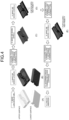
- Shapes of a press forming die acquired in steps in an invention example in which the above embodiment was carried out are illustrated in FIG. 4 along a flow of the steps. Each of the steps of the invention example will be described with reference to FIG. 4 .
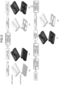
- FIG. 5 a flow of steps of a method of repeating making of CAD data of a die and making of a die model by a solid model is illustrated in FIG. 5 .
- steps 1 to 4 in the comparative example are the same as those in the invention example.
- FIG. 7 A comparison of required time (modeling time and calculation time) in the invention example and the comparative example is illustrated in FIG. 7 .
- the modeling time in the comparative example was 60 min
- the calculation time was 200 min
- a total was 260 min.
- the modeling time in the example was 5 min
- the calculation time was 130 min
- the total was 135 min
- 48% of the calculation time in the comparative example could be shortened.
- steps of making CAD data of a die, making the die model a (solid) based thereon, and acquiring a press forming load of the die model a (solid) are performed.
- the present invention may be applied by utilization of these pieces of data. That is, in the present invention, it is not essential to make the CAD data of a die and the die model a (solid).
- a real press-forming die was manufactured based on design stiffness distributions of the press forming die with which the press formed part 31 in FIG. 3 was formed, the design stiffness distributions being acquired in the first example (die design stiffness distributions acquiring step), and the press formed part 31 was press-formed by utilization of the real press-forming die.
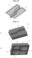
- FIG. 10 is a view illustrating design stiffness distributions 43 in the die model c (shell) of the first example.
- FIG. 10 corresponds to a die in a real press-forming die (punch, die, and the like) with which a part illustrated in FIG. 3 is formed.
- a punch or the like that is another real press-forming die has a shape corresponding to the die.
- the real press-forming die (die) will be described below as an example.
- a color of a portion 45 having high rigidity is dark gray.
- FIG. 11 A real press-forming die 47 manufactured based on the design stiffness distributions 43 of the press forming die of FIG. 10 is illustrated in FIG. 11 .
- a groove shape portion 49 corresponding to the part is formed on a forming surface side of the real press-forming die 47, and first R portions 51 corresponding to shoulder parts of a punch 39 of the press formed part 31 are respectively included on both sides of a groove bottom.
- a second R portion 53 corresponding to a shoulder part of a die 41 of the press formed part 31 is provided at an inlet of the groove.
- the real press-forming die 47 is a rib portion 55 in which a peripheral edge is not deformed in a manner corresponding to a portion 45 that has high rigidity and that is dark gray in the design stiffness distributions 43 of the press forming die in FIG. 10 .
- a portion corresponding to the groove bottom is also a portion corresponding to a rib 57 which portion is not deformed.
- a portion other than the rib portion 55 and the portion corresponding to the rib 57 is a deformed portion, and a thickness thereof is 10 mm calculated by the expression (1).
- An actual press forming load of when the press formed part 31 was press-formed by utilization of the real press-forming die 47 was 240 ton and was 2.1% lower than the maximum load (245 ton) due to mechanical restriction of the press machine. From this, it was shown that the press formed part 31 can be manufactured by the real press-forming die 47 having an appropriate press forming load corresponding to the pressurizing capacity of the press machine according to the present invention.
- the present invention it is possible to provide a method, device, and program of designing a press forming die which can be designed in a short time and with which a press forming load is reduced. Furthermore, according to the present invention, it is possible to provide a manufacturing method of a press formed part in which method a press formed part is manufactured by a real press-forming die manufactured based on a designed press forming die.
Landscapes
- Engineering & Computer Science (AREA)
- Physics & Mathematics (AREA)
- Theoretical Computer Science (AREA)
- Geometry (AREA)
- General Physics & Mathematics (AREA)
- Evolutionary Computation (AREA)
- General Engineering & Computer Science (AREA)
- Computer Hardware Design (AREA)
- Computational Mathematics (AREA)
- Mathematical Analysis (AREA)
- Mathematical Optimization (AREA)
- Pure & Applied Mathematics (AREA)
- Mechanical Engineering (AREA)
- Shaping Metal By Deep-Drawing, Or The Like (AREA)
- Mounting, Exchange, And Manufacturing Of Dies (AREA)
Abstract
Description
- The present invention relates to a method, device, and program of designing a press forming die capable of reducing a press forming load that is associated with press forming of a metal member and that acts on the press forming die, and a method of manufacturing a press formed part. The metal member may be a hot rolled steel sheet, a cold rolled steel sheet, a galvanized steel sheet obtained by subjecting a steel sheet to surface treatment (such as electro-galvanizing, hot-dip galvanizing, or organic coating treatment), or a sheet made of various metals such as a stainless steel, aluminum, and magnesium. Background
- Application of a high-tensile steel sheet in an automotive body is expanding due to an increasing need for improving fuel efficiency by weight reduction of the automotive body and for improving collision safety. With respect to the high-tensile steel sheet, deterioration in formability due to low ductility and deterioration in dimensional accuracy due to high material strength are problems to be solved for application of the high-tensile steel sheet.
- In addition, since a press forming load increases when the high-tensile steel sheet is press-formed, it is necessary to change a press forming process line or to divide parts. Such an increase in the press forming load is also a hindrance to the application of the high-tensile steel sheet. Thus, there is a demand for a press forming die capable of reducing the press forming load without changing the press forming process line or dividing parts.
- In this regard,
Patent Literature 1 discloses a method of reducing a press forming load by divisionally moving a press forming die and sequentially performing forming. - In addition, three-dimensional computer aided design (CAD) has been conventionally used for structural design of a press forming die that is a three-dimensional structure, and a solid model (three-dimensional element) has been used for three-dimensional modeling of the press forming die. When the die model is made by the solid model, a contact between parts included in the press forming die is possible, and designing of the press forming die in consideration of interlocking between die parts becomes possible. Non-Patent
Literature 1 discloses a method of predicting a press forming load with a press forming die being an elastic body. - Patent Literature 1:
Japanese Patent Application Laid-open No. 2010-207907 - Non Patent Literature 1: Shoichiro Ohmachi, "Load examination of press forming computer aided engineering (CAE) using 3DSimSTAMP, and application of the same", Press Working, Nikkan Kogyo Shimbun, Ltd., March 2015, Vol. 53, No. 3, p. 62-65
- Although
Patent Literature 1 proposes a structure in which a press forming load is reduced by division of a press forming die, a method of examining a press-forming die structure is not described. - Non-Patent
Literature 1 discloses a case of a press forming analysis by a die model using a solid model (three-dimensional element) of an elastic body. In a case where stiffness of a press forming die is designed as a structure of the press forming die, it is necessary to make a die model by using a solid model (three-dimensional element) of an elastic body, perform finite element analysis (FEM analysis) by using the made die model of the three-dimensional element, change the structure of the die model in such a manner as to reduce a press forming load, and design the press-forming die structure. However, an FEM analysis calculation in which the press forming die is modeled by utilization of the solid model (three-dimensional element) requires calculation time, and modeling of the die model is required every time the structure of the die model is changed, whereby it takes time to design the die. - The present invention has been made in view of the above problems, and an object thereof is to provide a method, device, and program of designing a press forming die which can be designed in a short period and in which a press forming load is reduced. Furthermore, another object of the present invention is to provide a manufacturing method of a press formed part in which method the press formed part is manufactured with a real press-forming die manufactured based on a designed press forming die. Solution to Problem
- In examining a method of designing a structure of a press forming die capable of reducing a press forming load by using a press forming analysis using a finite element method, the inventors first examined a phenomenon in which the press forming load increases.
- From the examination by press forming tests and the press forming analysis, the inventors have found that the press forming load rapidly increases near the bottom dead center of press-forming. In addition, the inventors have found that a load near the bottom dead center of pressing includes not only reaction force due to deformation of the press formed part (blank) but also reaction force of controlling elastic deformation of the press forming die by stiffness due to the press-forming die structure. The elastic deformation of the press forming die is caused by contact between facing press forming dies via a press formed part that almost reaches a deformation limit.
- Then, the inventors have obtained an idea that, in a portion where a press forming load (surface pressure) acts, the press forming load (surface pressure) of the portion can be reduced by reduction of the stiffness of the press forming die and reduction of the reaction force of controlling the elastic deformation of the press forming die. In addition, the inventors have considered that, in order to reduce the stiffness of the press forming die, analysis is to be performed with a focus on stiffness distributions of the press forming die when the press forming analysis using the finite element method is performed.
- Furthermore, the inventors have found the following. That is, in order to provide the stiffness distributions of the press forming die, it is not necessary to form the press forming die into a solid model (three-dimensional element) while keeping the press-forming die structure as is conventionally performed. When the press forming die is formed into a model with a surface of the press forming die being provided with a virtual thickness as a shell model (two-dimensional element) having nonrigidity (elasticity or elasto-plasticity), and stiffness is provided by a boundary condition, it is possible to obtain press load estimation accuracy substantially the same as that in a case of solid modeling and to shorten the calculation time. The present invention is based on such findings, and specifically includes the following configurations.
- A designing method of a press forming die according to the present invention reduces a press forming load, and includes: a die model making step of making a die model in which a surface of the press forming die is provided with a virtual thickness by a nonrigid two-dimensional element; a die model stiffness distribution setting step of setting stiffness distributions of the die model by making a boundary condition of the two-dimensional element vary depending on a portion of the die model; a press forming load acquiring step of acquiring a press forming load by performing a press forming analysis by using the die model in which the stiffness distributions are set; a press forming load determining step of determining whether the press forming load is within a predetermined range of the press forming load; and a press forming die design stiffness determining step of determining the set stiffness distributions of the die model as design stiffness distributions of the press forming die in a case where it is determined in the press forming load determining step that the press forming load is within the predetermined range of the press forming load, and changing the stiffness distributions of the die model in the die model stiffness distribution setting step and repeating the press forming load acquiring step and the press forming load determining step until the press forming load falls within the predetermined range of the press forming load in a case where it is determined in the press forming load determining step that the predetermined range of the press forming load is not within the predetermined range of the press forming load , and determining the changed stiffness distributions of the die model as the design stiffness distributions of the press forming die when the press forming load falls within the predetermined range of the press forming load.
- The boundary condition in the die model stiffness distribution setting step may be any one or combination of: displacement restraint; Young's modulus; a sheet thickness; density; mass; and yield strength.
- The nonrigid two-dimensional element may be an elastic or elasto-plastic two-dimensional element.
- A designing device of a press forming die according to the present invention reduces a press forming load, and includes: a die model making unit configured to make a die model in which a surface of the press forming die is provided with a virtual thickness by a nonrigid two-dimensional element; a die model stiffness distribution setting unit configured to set stiffness distributions of the die model by making a boundary condition of the two-dimensional element vary depending on a portion of the die model; a press forming load acquisition unit configured to acquire a press forming load by performing a press forming analysis by using the die model in which the stiffness distributions are set; a press forming load determination unit configured to determine whether the press forming load is within a predetermined range of press forming load; and a press forming die design stiffness determination unit configured to determine the set stiffness distributions of the die model as design stiffness distributions of the press forming die in a case where it is determined by the press forming load determination unit that the press forming load is within the predetermined range of press forming load, and change the stiffness distributions of the die model in the die model stiffness distribution setting unit and repeat the processing of the press forming load acquisition unit and the press forming load determination unit until the press forming load falls within the predetermined range of the press forming load in a case where it is determined by the press forming load determination unit that the predetermined range of the press forming load is not within the predetermined range of press forming load , and determine the changed stiffness distributions of the die model as the design stiffness distributions of the press forming die when the press forming load falls within the predetermined range of the press forming load.
- A designing program of a press forming die according to the present invention causes a computer to function as the designing device of the press forming die according to the present invention.
- A manufacturing method of a press formed part according to the present invention includes: a press forming die design stiffness distributions acquiring step of acquiring design stiffness distributions of a press forming die by the designing method of a press forming die according to the present invention; a press forming die manufacturing step of manufacturing a real press-forming die based on the acquired design stiffness distributions of the press forming die; and a press forming step of performing press forming by using the real press-forming die.
- According to the present invention, a structure of a press forming die capable of reducing a press forming load can be designed in a short time. As a result, it is possible to manufacture a press formed part by using a real press-forming die having an appropriate press forming load corresponding to pressurizing capacity of a press machine. As a result, it is possible to control a decrease in a life of the press forming die due to excessive pressurization to the press forming die, and it is possible to control generation of a burr and the like of the press formed part and to improve manufacturing efficiency.
-
-
FIG. 1 is a flowchart of a designing method of a press forming die according to a first embodiment. -
FIG. 2 is a block diagram illustrating a configuration of a designing device of a press forming die according to a second embodiment. -
FIG. 3 is a view for describing a shape of a part to be formed in an example. -
FIG. 4 is a view for describing a shape of a press forming die corresponding to each step of an invention example in the example. -
FIG. 5 is a view for describing a shape of a press forming die corresponding to each step of a comparative example in the example. -
FIG. 6 is a graph illustrating press forming loads in press forming dies of the invention example and the comparative example. -
FIG. 7 is a graph illustrating required time of the invention example and the comparative example. -
FIG. 8 is a flowchart of a manufacturing method of a press formed part according to a third embodiment. -
FIG. 9 is a view for describing a determination method of a thickness of a real press-forming die. -
FIG. 10 is a view illustrating design stiffness distributions in a die model of a first example. -
FIG 11 . is a view for describing a real press-forming die 47 manufactured based on the design stiffness distributions of the press forming die inFIG. 10, FIG. 11(a) being a view of a forming surface, andFIG. 11(b) being a view of a lower surface of the die. - The present embodiment is a designing method of a press forming die capable of reducing a press forming load. As illustrated in
FIG. 1 , the designing method of the press forming die includes a die model making step (S1), a die model stiffness distribution setting step (S3), a press forming load acquiring step (S5), a press forming load determining step (S7), and a press forming die design stiffness determining step (S9). Each configuration will be described below. - The die model making step S1 is a step of making a die model in which a surface of a press forming die is provided with a virtual thickness by a nonrigid two-dimensional element (shell element). The nonrigid body means an elastic body or an elasto-plastic body, and an elastic or elasto-plastic two-dimensional element may be used as the nonrigid two-dimensional element (shell element). Providing the shell element with the virtual thickness is one of procedures of when the shell element is used in a normal press forming analysis.
- The die model stiffness distribution setting step S3 is a step of setting the stiffness distributions of the die model by making a boundary condition of the two-dimensional element vary depending on a portion of the die model. The boundary condition may be a displacement restraint, Young's modulus, a sheet thickness, a density, mass, or yield strength. For example, in a case where the boundary condition is the displacement restraint, in a case where a specific range of the press forming die is set to have high rigidity, the boundary condition may be set in such a manner that displacement of the two-dimensional element in the portion having the high rigidity is restrained and deformation is prevented. Similarly, in a case where the boundary condition is the Young's modulus, the sheet thickness, the density, the mass, or the yield strength, in a case where a specific range of the press forming die is set to have high rigidity, the boundary condition may be set in such a manner that the Young's modulus, the sheet thickness, the density, the mass, or the yield strength of the two-dimensional element in the portion having the high rigidity is increased and that deformation becomes less likely.
- The press forming load acquiring step S5 is a step of performing a press forming analysis by using the die model in which the stiffness distributions are set, and acquiring the press forming load. The press forming load to be acquired may be a load applied to the entire press forming die or a contact pressure distribution of the press forming die.
- The press forming load determining step S7 is a step of determining whether the press forming load is within a predetermined range of the press forming load. The predetermined range of the press forming load is a maximum load of a press forming machine, load restriction for reducing wear of the press forming die, load restriction for reducing a vibration of the press forming die, or the like.
- In the press forming die design stiffness determining step S9, in a case where it is determined in the press forming load determining step S7 that the press forming load is within the predetermined range of the press forming load, the set stiffness distributions of the die model are determined as design stiffness distributions of the press forming die. In addition, in a case where it is determined in the press forming load determining step S7 that the predetermined range of the press forming load is not satisfied, the stiffness distributions of the die model in the die model stiffness distribution setting step S3 are changed, and the press forming load acquiring step S5 and the press forming load determining step S7 are repeated until the predetermined range of the press forming load is satisfied. Then, when the predetermined range of the press forming load is reached, the changed stiffness distributions of the die model are determined as the design stiffness distributions of the press forming die.
- In order to reflect the determined design stiffness distributions in the press forming die, for example, a thickness is changed or members having different Young's modulus are used according to a degree of the stiffness.
- In the present embodiment, the press forming die is formed into a model with a surface of the press forming die being provided with a virtual thickness as a nonrigid (elastic or elasto-plastic) shell model (two-dimensional element), and stiffness is provided by the boundary condition. Thus, the FEM analysis calculation for acquiring the press forming load does not take time, and it is not necessary to perform modeling of the die model each time the stiffness distribution setting is changed. As a result, it becomes possible to design the structure of the press forming die capable of reducing a press forming load in a short time.
- It is possible to realize the designing method of a press forming die described in the first embodiment by causing a computer to execute a preset program. A press forming die designing device as an example of such a device will be described in the present embodiment. As illustrated in
FIG. 2 , a designingdevice 1 of a press forming die according to the present embodiment is configured by a computer such as a personal computer (PC), and includes adisplay device 3, aninput device 5, amemory storage 7, a workingdata memory 9, and anarithmetic processing unit 11. Then, thedisplay device 3, theinput device 5, thememory storage 7, and the workingdata memory 9 are connected to thearithmetic processing unit 11, and functions thereof are executed by commands from thearithmetic processing unit 11. Hereinafter, with a press formedpart 31 illustrated inFIG. 3 as an analysis target, each configuration of the designingdevice 1 of the press forming die according to the present embodiment will be described. - The
display device 3 is used for displaying of an analysis result or the like, and includes an LCD monitor or the like. - The
input device 5 is used, for example, for display instructions of a blank, the press formedpart 31, and the like and a condition input by an operator, and includes a keyboard, a mouse, and the like. - The
memory storage 7 is used, for example, to store CAD data of a die, various files such as shape files of the blank and the press formedpart 31, and includes a hard disk or the like. - The working
data memory 9 is used for temporary storage and calculation of data used by thearithmetic processing unit 11, and includes a random access memory (RAM) or the like. - As illustrated in
FIG. 2 , thearithmetic processing unit 11 includes a diemodel making unit 13, a die model stiffnessdistribution setting unit 15, a press formingload acquisition unit 17, a press formingload determination unit 19, and a press forming die designstiffness determination unit 21, and is configured by a central processing unit (CPU). Each of these units functions when the CPU executes a predetermined program. The functions of the above units in thearithmetic processing unit 11 will be described below. - The die
model making unit 13 is to make a die model in which a surface of a press forming die is provided with a virtual thickness by a nonrigid two-dimensional element, and executes the die model making step S1 described in the first embodiment. - The die model stiffness
distribution setting unit 15 is to set stiffness distributions of the die model by making a boundary condition of the two-dimensional element vary depending on a portion of the die model, and executes the die model stiffness distribution setting step S3 described in the first embodiment. - The press forming
load acquisition unit 17 is to perform a press forming analysis by using the die model in which the stiffness distributions are set and to acquire a press forming load, and executes the press forming load acquiring step S5 described in the first embodiment. - The press forming
load determination unit 19 is to determine whether the press forming load is within a predetermined range of the press forming load, and executes the press forming load determining step S7 described in the first embodiment. - In a case where it is determined by the press forming
load determination unit 19 that the press forming load is within the predetermined range of the press forming load, the press forming die designstiffness determination unit 21 determines the set stiffness distributions of the die model as design stiffness distributions of the press forming die. On the other hand, in a case where the press formingload determination unit 19 determines that the predetermined range of the press forming load is not satisfied, the press forming die designstiffness determination unit 21 changes the stiffness distributions of the die model in the die model stiffnessdistribution setting unit 15 and repeats the processing of the press formingload acquisition unit 17 and the press formingload determination unit 19 until the predetermined range of the press forming load is satisfied. Then, the press forming die designstiffness determination unit 21 determines the changed stiffness distributions of the die model as the design stiffness distributions of the press forming die when the predetermined range of the press forming load is reached. The press forming die designstiffness determination unit 21 executes the press forming die design stiffness determining step S9 described in the first embodiment. - According to the designing
device 1 of the press forming die according to the present embodiment, a structure of the press forming die capable of reducing the press forming load can be designed in a short time similarly to the first embodiment. - As described above, the die
model making unit 13, the die model stiffnessdistribution setting unit 15, the press formingload acquisition unit 17, the press formingload determination unit 19, and the press forming die designstiffness determination unit 21 in the designingdevice 1 of the press forming die of the present embodiment are realized by the CPU executing a predetermined program. Thus, a designing program of a press forming die according to the present invention can be specified as what causes the computer to function as the diemodel making unit 13, the die model stiffnessdistribution setting unit 15, the press formingload acquisition unit 17, the press formingload determination unit 19, and the press forming die designstiffness determination unit 21. - A manufacturing method of a press formed part according to the third embodiment of the present invention is to manufacture a real press-forming die based on design stiffness distributions of a press forming die acquired by the designing method of the press forming die described in the first embodiment, and to manufacture a press formed part by using the real press-forming die. As illustrated in
FIG. 8 , the manufacturing method of the press formed part includes a press forming die design stiffness distributions acquiring step S11, a press forming die manufacturing step S13, and a press forming step S15. - The press forming die design stiffness distributions acquiring step S11 is a step of acquiring design stiffness distributions of a press forming die by the designing method of the press forming die of the first embodiment described above. The design stiffness distributions of the press forming die which distributions are acquired in the press forming die design stiffness distributions acquiring step S11 are acquired by determination of changed stiffness distributions of the die model as the design stiffness distributions of the press forming die when a predetermined range of a press forming load is reached in the press forming die design stiffness determining step S9 described above.
- The press forming die manufacturing step S13 is a step of manufacturing a real press-forming die based on the design stiffness distributions of the press forming die which distributions are acquired in the press forming die design stiffness distributions acquiring step S11. In the press forming die manufacturing step S13, based on the design stiffness distributions of the press forming die, for example, a rib (stiffened member) is arranged at a portion at which a boundary condition is set in such a manner that deformation of the two-dimensional element is restrained and deformation is prevented and which has high rigidity, and a thickness of the real press-forming die in the other portion is determined in such a manner that a deflection amount becomes the same as that of the die model.
- Hereinafter, a concept of a method of determining the thickness of the real press-forming die will be described with reference to
FIG. 9 . InFIG. 9 , elastic deformation of a surface of a die is considered and illustrated as deformation of a simple beam.FIG. 9(a) is a view illustrating a case where the thickness of the real press-forming die is t (mm) and Young's modulus is E (MPa), andFIG. 9(b) is a view illustrating a case where a virtual thickness of the die model is tc (mm) and the Young's modulus is Ec (MPa). In such a manner, the thickness t of the real press-forming die in which a deflection amount δ of the real press-forming die inFIG. 9(a) and a deflection amount δc of the die model inFIG. 9(b) are the same can be determined by an expression (1).
- The press forming step S15 is a step of actually performing press forming by using the real press-forming die manufactured in the press forming die manufacturing step S13 and of manufacturing the press formed part.
- As described above, in the manufacturing method of the press formed part according to the third embodiment, it is possible to manufacture the press formed part by using the real press-forming die having an appropriate press forming load corresponding to pressurizing capacity of a press forming machine. As a result, it is possible to control a decrease in a life of the press forming die due to excessive pressurization to the press forming die, and it is possible to control generation of a burr or the like of the press formed part and to improve manufacturing efficiency.
- A specific press forming die was designed to confirm an effect of the present invention, and will be described below. A part shape that is a target of the example is illustrated in
FIG. 3 . A material of the part is a 1180 MPa-class high-tensile steel sheet having a sheet thickness of 1.6 mm. In press forming of the part, it is necessary to control a cold press load to a maximum load of 245 ton or less due to mechanical restriction of a press machine. Thus, a predetermined press forming load in a forming load determining step in the designing method of the press forming die of the present invention is set to the maximum load of the press forming machine, which is 245 ton. - Shapes of a press forming die acquired in steps in an invention example in which the above embodiment was carried out are illustrated in
FIG. 4 along a flow of the steps. Each of the steps of the invention example will be described with reference toFIG. 4 . - 1. First, CAD data of a die of a press forming die was made (
FIG. 4(A) ). - 2. Then, a mesh model of the press forming die was made, and a die model a (solid) by a solid model (three-dimensional element) of a rigid body was made (
FIG. 4(B) ). - 3. A press forming analysis of the press formed
part 31 having the part shape illustrated inFIG. 3 was performed by an FEM analysis using the die model a (solid), and a press forming load was acquired. - 4. Then, press forming load determination was performed to determine whether the press forming load of the die model a (solid) was equal to or lower than the maximum load of 245 ton. As a result, since the press forming load was 338 ton and exceeded the maximum load of 245 ton by 38.0%, it was determined that further reduction of the press forming load was necessary. Thus, in 5 to 13 in the following, a press forming die capable of reducing the press forming load was designed by utilization of the method and device of designing a press forming die according to the present embodiment.
- 5. A die model (shell) in which a surface of the press forming die was provided with a virtual thickness by an elastic (nonrigid) shell element (two-dimensional element) was made (
FIG. 4(C) , die model making step). - 6. Then, a highly rigid portion of the press forming die was set in such a manner as not to be displaced by restraint of displacement of the die model (shell) in the range, the displacement of the die model (shell) in the other range was not restrained, and the stiffness distributions of the die model (shell) were set by the boundary condition varied depending on the portion of the die model (shell), whereby a die model b (shell) was made (
FIG. 4(D) , die model stiffness distribution setting step). - 7. A press forming analysis by the FEM analysis using the die model b (shell) in which the stiffness distributions were set was performed, and a press forming load was acquired (press forming load acquiring step).
- 8. It was determined whether the press forming load of the die model b (shell) was equal to or lower than the maximum load of the press forming machine which maximum load was 245 ton. It was determined that the acquired press forming load of the die model b (shell) was 250 ton and exceeded the maximum load of 245 ton, that further reduction of the press forming load was necessary, and that a predetermined range of the press forming load was not satisfied (press forming load determining step).
- 9. A die model c (shell) in which the stiffness distributions of the die model were changed by a change in the portion, in which the displacement of the die model (shell) was set to be restrained in the die model b (shell), to be narrower than that of the die model b (shell) was made (
FIG. 4(E) , die model stiffness distribution setting step repeatedly performed in the press forming die design stiffness determining step). - 10. A press forming analysis using the die model c (shell) in which the stiffness distributions were changed was performed, and a press forming load was acquired (press forming load acquiring step repeatedly performed in the press forming die design stiffness determining step).
- 11. It was determined whether the acquired press forming load of the die model c (shell) was equal to or lower than the maximum load of 245 ton (press forming load determining step repeatedly performed in the press forming die design stiffness determining step). As a result, the press forming load of the die model c (shell) was 234 ton and was reduced to 4.5% below the maximum load of 245 ton. Thus it was determined that the press forming load was within the predetermined range of the press forming load (press forming load determining step repeatedly performed in the press forming die design stiffness determining step) .
- 12. Since the press forming load of the die model c (shell) falls within the predetermined range of the press forming load, the stiffness distributions of the die model c (shell) were determined as the design stiffness distributions of the press forming die of the press formed
part 31 having the part shape illustrated inFIG. 3 . - 13. Thus, the examination was ended. The steps indicated by 9 to 12 in the above correspond to the press forming die design stiffness determining step of the present invention, the step being a step of determining the stiffness distributions of the die model by the shell model as the design stiffness distributions of the press forming die by changing the stiffness distributions of the die model (shell) and repeating the press forming load acquiring step and the press forming load determining step until the press forming load falls within the predetermined range of the press forming load in order to reduce the press forming load.
- As a comparative example, a flow of steps of a method of repeating making of CAD data of a die and making of a die model by a solid model is illustrated in
FIG. 5 . Each of the steps of the comparative example will be described with reference toFIG. 5 . Note that steps 1 to 4 in the comparative example are the same as those in the invention example. - 1. First, CAD data of a die of a press forming die was made (
FIG. 5(a) ). - 2. Then, a mesh model of the press forming die was made, and a die model a (solid) (same as the die model a in the invention example) by a solid model (three-dimensional element) of a rigid body was made (
FIG. 5(b) ). - 3. A press forming analysis of the press formed
part 31 having the part shape illustrated inFIG. 3 was performed by an FEM analysis using the die model a (solid), and a press forming load was acquired. - 4. Then, press forming load determination was performed to determine whether the press forming load of the die model a (solid) was equal to or lower than the maximum load of 245 ton. Here, since the press forming load was 338 ton as described in the invention example and exceeded the maximum load of 245 ton by 38.0%, it was determined that further reduction of the press forming load was necessary.
- 5. A press-forming die structure was reviewed, and the CAD data of a die of the press forming die in which the press-forming die structure was changed was made (
FIG. 5(c) ). - 6. From the CAD data of a die of the press forming die in which the press-forming die structure was changed, a mesh model of the press forming die was made, and a die model b (solid) by a solid model of a rigid body was made (
FIG. 5(d) ). - 7. A press forming load was acquired by performance of a press forming analysis by an FEM analysis using the made die model b (solid).
- 8. The press forming load of the die model b (solid) was 248 ton and was slightly more than the maximum load of 245 ton by 1.2%, and it was determined that further reduction of the press forming load was necessary.
- 9. In order to further reduce the press forming load, the press-forming die structure was reviewed, and the CAD data of a die of the press forming die in which the press-forming die structure was changed again was made (
FIG. 5(e) ). - 10. From the CAD data of a die of the press forming die in which the press-forming die structure was changed again, a mesh model of the press forming die was made, and a die model c (solid) by a solid model of a rigid body was made (
FIG. 5(f) ). - 11. A press forming load was acquired by performance of a press forming analysis by an FEM analysis using the made die model c (solid).
- 12. Since the press forming load of the die model c (solid) was 228 ton and was reduced to 6.9% lower than the maximum load of 245 ton, the press forming load determination was OK.
- 13. Since the press forming load of the die model c (solid) falls within the predetermined range of the press forming load, the stiffness distributions of the die model c (solid) were determined as the design stiffness distributions of the press forming die of the press formed
part 31 having the part shape illustrated inFIG. 3 . - 14. Thus, the examination was completed.
- Press forming loads obtained by the press forming analysis using the die model a (solid), the die model b (shell) of the shell element according to the present invention, and the die model c (shell) and press forming loads of the die model b (solid) and the die model c (solid) of the solid element obtained by the comparative example are compared and illustrated in
FIG. 6 This shows that the die model b (shell) and the die model c (shell) of the shell element and the die model b (solid) and the die model c (solid) of the solid element have substantially the same press load estimation accuracy. - A comparison of required time (modeling time and calculation time) in the invention example and the comparative example is illustrated in
FIG. 7 . As illustrated inFIG. 7 , the modeling time in the comparative example was 60 min, the calculation time was 200 min, and a total was 260 min. On the other hand, the modeling time in the example was 5 min, the calculation time was 130 min, and the total was 135 min, and 48% of the calculation time in the comparative example could be shortened. - As described above, it is demonstrated that it is possible to shorten the design time without impairing the accuracy by application of the present invention.
- In the invention example in the above example, steps of making CAD data of a die, making the die model a (solid) based thereon, and acquiring a press forming load of the die model a (solid) are performed. However, since there is a case where the CAD data of a die and the die model a (solid) already exist. In that case, the present invention may be applied by utilization of these pieces of data. That is, in the present invention, it is not essential to make the CAD data of a die and the die model a (solid).
- In the second example, a real press-forming die was manufactured based on design stiffness distributions of the press forming die with which the press formed
part 31 inFIG. 3 was formed, the design stiffness distributions being acquired in the first example (die design stiffness distributions acquiring step), and the press formedpart 31 was press-formed by utilization of the real press-forming die. -
FIG. 10 is a view illustratingdesign stiffness distributions 43 in the die model c (shell) of the first example.FIG. 10 corresponds to a die in a real press-forming die (punch, die, and the like) with which a part illustrated inFIG. 3 is formed. A punch or the like that is another real press-forming die has a shape corresponding to the die. The real press-forming die (die) will be described below as an example. InFIG. 10 , a color of aportion 45 having high rigidity is dark gray. - A real press-forming
die 47 manufactured based on thedesign stiffness distributions 43 of the press forming die ofFIG. 10 is illustrated inFIG. 11 . Agroove shape portion 49 corresponding to the part is formed on a forming surface side of the real press-formingdie 47, andfirst R portions 51 corresponding to shoulder parts of apunch 39 of the press formedpart 31 are respectively included on both sides of a groove bottom. Asecond R portion 53 corresponding to a shoulder part of adie 41 of the press formedpart 31 is provided at an inlet of the groove. - As illustrated in
FIG. 11 , the real press-formingdie 47 is arib portion 55 in which a peripheral edge is not deformed in a manner corresponding to aportion 45 that has high rigidity and that is dark gray in thedesign stiffness distributions 43 of the press forming die inFIG. 10 . In addition, a portion corresponding to the groove bottom is also a portion corresponding to arib 57 which portion is not deformed. A portion other than therib portion 55 and the portion corresponding to therib 57 is a deformed portion, and a thickness thereof is 10 mm calculated by the expression (1). - An actual press forming load of when the press formed
part 31 was press-formed by utilization of the real press-formingdie 47 was 240 ton and was 2.1% lower than the maximum load (245 ton) due to mechanical restriction of the press machine. From this, it was shown that the press formedpart 31 can be manufactured by the real press-formingdie 47 having an appropriate press forming load corresponding to the pressurizing capacity of the press machine according to the present invention. - According to the present invention, it is possible to provide a method, device, and program of designing a press forming die which can be designed in a short time and with which a press forming load is reduced. Furthermore, according to the present invention, it is possible to provide a manufacturing method of a press formed part in which method a press formed part is manufactured by a real press-forming die manufactured based on a designed press forming die.
-
- 1 DESIGNING DEVICE OF PRESS FORMING DIE
- 3 DISPLAY DEVICE
- 5 INPUT DEVICE
- 7 MEMORY STORAGE
- 9 WORKING DATA MEMORY
- 11 ARITHMETIC PROCESSING UNIT
- 13 DIE MODEL MAKING UNIT
- 15 DIE MODEL STIFFNESS DISTRIBUTION SETTING UNIT
- 17 PRESS FORMING LOAD ACQUISITION UNIT
- 19 PRESS FORMING LOAD DETERMINATION UNIT
- 21 PRESS FORMING DIE DESIGN STIFFNESS DETERMINATION UNIT
- 31 PRESS FORMED PART
- 33 TOP PORTION
- 35 SIDE WALL PORTION
- 37 FLANGE PORTION
- 39 SHOULDER PART OF PUNCH
- 41 SHOULDER PART OF DIE
- 43 DESIGN STIFFNESS DISTRIBUTION OF PRESS FORMING DIE
- 45 PORTION WITH HIGH RIGIDITY
- 47 REAL PRESS-FORMING DIE
- 49 GROOVE SHAPE PORTION
- 51 FIRST R PORTION
- 53 SECOND R PORTION
- 55 RIB PORTION
- 57 PORTION CORRESPONDING TO RIB
Claims (6)
- A designing method of a press forming die for reducing a press forming load, comprising:a die model making step of making a die model in which a surface of the press forming die is provided with a virtual thickness by a nonrigid two-dimensional element;a die model stiffness distribution setting step of setting stiffness distributions of the die model by making a boundary condition of the two-dimensional element vary depending on a portion of the die model;a press forming load acquiring step of acquiring a press forming load by performing a press forming analysis by using the die model in which the stiffness distributions are set;a press forming load determining step of determining whether the press forming load is within a predetermined range of the press forming load; anda press forming die design stiffness determining step ofdetermining the set stiffness distributions of the die model as design stiffness distributions of the press forming die in a case where it is determined in the press forming load determining step that the press forming load is within the predetermined range of the press forming load, andchanging the stiffness distributions of the die model in the die model stiffness distribution setting step and repeating the press forming load acquiring step and the press forming load determining step until the press forming load falls within the predetermined range of the press forming load in a case where it is determined in the press forming load determining step that the predetermined range of the press forming load is not within the predetermined range of the press forming load , and determining the changed stiffness distributions of the die model as the design stiffness distributions of the press forming die when the press forming load falls within the predetermined range of the press forming load.
- The designing method of a press forming die according to claim 1, wherein the boundary condition in the die model stiffness distribution setting step is any one or combination of: displacement restraint; Young's modulus; a sheet thickness; density; mass; and yield strength.
- The designing method of a press forming die according to claim 1 or 2, wherein the nonrigid two-dimensional element is an elastic or elasto-plastic two-dimensional element.
- A designing device of a press forming die for reducing a press forming load, comprising:a die model making unit configured to make a die model in which a surface of the press forming die is provided with a virtual thickness by a nonrigid two-dimensional element;a die model stiffness distribution setting unit configured to set stiffness distributions of the die model by making a boundary condition of the two-dimensional element vary depending on a portion of the die model;a press forming load acquisition unit configured to acquire a press forming load by performing a press forming analysis by using the die model in which the stiffness distributions are set;a press forming load determination unit configured to determine whether the press forming load is within a predetermined range of press forming load; anda press forming die design stiffness determination unit configured todetermine the set stiffness distributions of the die model as design stiffness distributions of the press forming die in a case where it is determined by the press forming load determination unit that the press forming load is within the predetermined range of press forming load, andchange the stiffness distributions of the die model in the die model stiffness distribution setting unit and repeat the processing of the press forming load acquisition unit and the press forming load determination unit until the press forming load falls within the predetermined range of the press forming load in a case where it is determined by the press forming load determination unit that the predetermined range of the press forming load is not within the predetermined range of press forming load , and determine the changed stiffness distributions of the die model as the design stiffness distributions of the press forming die when the press forming load falls within the predetermined range of the press forming load.
- A designing program of a press forming die, the program causing a computer to function as the designing device of the press forming die according to claim 4.
- A manufacturing method of a press formed part, comprising:a press forming die design stiffness distributions acquiring step of acquiring design stiffness distributions of a press forming die by the designing method of a press forming die according to claim 1 or 2;a press forming die manufacturing step of manufacturing a real press-forming die based on the acquired design stiffness distributions of the press forming die; anda press forming step of performing press forming by using the real press-forming die.
Applications Claiming Priority (3)
| Application Number | Priority Date | Filing Date | Title |
|---|---|---|---|
| JP2022042034 | 2022-03-17 | ||
| JP2022189757A JP7338774B1 (en) | 2022-03-17 | 2022-11-29 | Press mold design method, apparatus and program, and method for manufacturing press molded products |
| PCT/JP2023/004617 WO2023176231A1 (en) | 2022-03-17 | 2023-02-10 | Design method, device, and program for press forming, and method for manufacturing press formed articles |
Publications (3)
| Publication Number | Publication Date |
|---|---|
| EP4475031A1 true EP4475031A1 (en) | 2024-12-11 |
| EP4475031A4 EP4475031A4 (en) | 2025-04-23 |
| EP4475031B1 EP4475031B1 (en) | 2026-01-21 |
Family
ID=87882199
Family Applications (1)
| Application Number | Title | Priority Date | Filing Date |
|---|---|---|---|
| EP23770192.5A Active EP4475031B1 (en) | 2022-03-17 | 2023-02-10 | Design method, device, and program for press forming, and method for manufacturing press formed articles |
Country Status (7)
| Country | Link |
|---|---|
| US (1) | US12691487B2 (en) |
| EP (1) | EP4475031B1 (en) |
| JP (1) | JP7338774B1 (en) |
| KR (1) | KR20240141331A (en) |
| CN (1) | CN118805172A (en) |
| MX (1) | MX2024010840A (en) |
| WO (1) | WO2023176231A1 (en) |
Families Citing this family (2)
| Publication number | Priority date | Publication date | Assignee | Title |
|---|---|---|---|---|
| JP7452713B1 (en) * | 2023-01-18 | 2024-03-19 | Jfeスチール株式会社 | Press mold design method and press mold manufacturing method |
| JP7740469B1 (en) * | 2024-09-04 | 2025-09-17 | Jfeスチール株式会社 | Press forming analysis method, press forming analysis device, and press forming analysis program |
Family Cites Families (7)
| Publication number | Priority date | Publication date | Assignee | Title |
|---|---|---|---|---|
| JP4305645B2 (en) * | 2003-11-04 | 2009-07-29 | トヨタ自動車株式会社 | Simulation method for sheet forming |
| JP4221589B2 (en) * | 2003-11-04 | 2009-02-12 | トヨタ自動車株式会社 | Simulation method of mold deflection distribution during press molding |
| JP2010207907A (en) | 2009-03-12 | 2010-09-24 | Nissan Motor Co Ltd | Pressing method and device |
| JP5795151B2 (en) * | 2010-06-03 | 2015-10-14 | Jfeスチール株式会社 | Molding analysis method for press parts |
| US20170140081A1 (en) * | 2014-07-30 | 2017-05-18 | Nippon Steel & Sumitomo Metal Corporation | Model setting method, forming simulation method, production method of forming tool, program, computer-readable recording medium having program recorded thereon, and finite element model |
| JP5832682B1 (en) * | 2015-03-31 | 2015-12-16 | 株式会社Jsol | Press mold shape automatic creation system and program, and press molding simulation system |
| DE102016125406A1 (en) * | 2016-12-22 | 2018-06-28 | Gkn Sinter Metals Engineering Gmbh | Die for a press |
-
2022
- 2022-11-29 JP JP2022189757A patent/JP7338774B1/en active Active
-
2023
- 2023-02-10 EP EP23770192.5A patent/EP4475031B1/en active Active
- 2023-02-10 US US18/835,807 patent/US12691487B2/en active Active
- 2023-02-10 MX MX2024010840A patent/MX2024010840A/en unknown
- 2023-02-10 CN CN202380027824.5A patent/CN118805172A/en active Pending
- 2023-02-10 KR KR1020247030198A patent/KR20240141331A/en active Pending
- 2023-02-10 WO PCT/JP2023/004617 patent/WO2023176231A1/en not_active Ceased
Also Published As
| Publication number | Publication date |
|---|---|
| EP4475031B1 (en) | 2026-01-21 |
| MX2024010840A (en) | 2024-09-17 |
| US20250128307A1 (en) | 2025-04-24 |
| WO2023176231A1 (en) | 2023-09-21 |
| EP4475031A4 (en) | 2025-04-23 |
| KR20240141331A (en) | 2024-09-26 |
| JP7338774B1 (en) | 2023-09-05 |
| CN118805172A (en) | 2024-10-18 |
| US12691487B2 (en) | 2026-07-28 |
| JP2023138296A (en) | 2023-10-02 |
Similar Documents
| Publication | Publication Date | Title |
|---|---|---|
| Esat et al. | Finite element analysis of springback in bending of aluminium sheets | |
| EP4475031B1 (en) | Design method, device, and program for press forming, and method for manufacturing press formed articles | |
| JP5910803B2 (en) | Method for evaluating plastic material and method for evaluating plastic working of plastic material | |
| Cai et al. | Multi-point forming of sandwich panels with egg-box-like cores and failure behaviors in forming process: Analytical models, numerical and experimental investigations | |
| EP3299793A1 (en) | Breakage prediction method, program, recording medium, and arithmetic processing device | |
| EP3151138A1 (en) | Model configuration method, forming simulation method, manufacturing method for forming tool, program, computer readable recording medium with program stored therein, and finite element model | |
| KR20110097899A (en) | A computer-readable recording medium recording a method for analyzing the cause of springback, a device for analyzing the cause of springback, and a program for analyzing the cause of springback. | |
| Kim et al. | Tool design in a multi-stage drawing and ironing process of a rectangular cup with a large aspect ratio using finite element analysis | |
| JP6070066B2 (en) | Springback amount evaluation method | |
| EP4575878A1 (en) | Press forming analysis method and device, press forming analysis program, and press-formed product manufacturing method | |
| EP4631639A1 (en) | Press die design method and press die production method | |
| JP4418452B2 (en) | Springback occurrence cause identifying method, apparatus thereof, and program thereof | |
| Jeong et al. | Influence of process variables on the stamping formability of aluminum wing nose rib | |
| JP7647800B2 (en) | PRESS FORMING ANALYSIS METHOD, PRESS FORMING CRACK DETECTION METHOD FOR PRESS FORMED PRODUCT, MANUFACTURING METHOD FOR PRESS FORMED PRODUCT, PRESS FORMING ANALYSIS DEVICE, PRESS FORMING ANALYSIS PROGRAM | |
| EP4563259A1 (en) | Method for identifying portion causing increase in forming load, method for manufacturing press formed part, device for identifying portion causing increase in forming load, and program for identifying portion causing increase in forming load | |
| JP7740469B1 (en) | Press forming analysis method, press forming analysis device, and press forming analysis program | |
| JP4308239B2 (en) | Springback influence display method, apparatus thereof, and program thereof | |
| JP2012214212A (en) | Structural member design method | |
| Araveeti | INTRODUCTION TO DEEP DRAWING | |
| JP4418449B2 (en) | Springback occurrence cause identifying method, apparatus thereof, and program thereof | |
| Uçan | Effect of constitutive modeling in sheet metal forming | |
| Nhaichaniya et al. | Advanced Sheet Metal Forming Using Finite Element Analysis | |
| Mondal et al. | Miniature Hemispherical Bowl-Shaped Forming Using SLA Punch and Die: Modeling and Experimental Analysis | |
| Pape | Engineering die structures for stamping advanced high strength steel parts |
Legal Events
| Date | Code | Title | Description |
|---|---|---|---|
| STAA | Information on the status of an ep patent application or granted ep patent |
Free format text: STATUS: THE INTERNATIONAL PUBLICATION HAS BEEN MADE |
|
| PUAI | Public reference made under article 153(3) epc to a published international application that has entered the european phase |
Free format text: ORIGINAL CODE: 0009012 |
|
| STAA | Information on the status of an ep patent application or granted ep patent |
Free format text: STATUS: REQUEST FOR EXAMINATION WAS MADE |
|
| 17P | Request for examination filed |
Effective date: 20240903 |
|
| AK | Designated contracting states |
Kind code of ref document: A1 Designated state(s): AL AT BE BG CH CY CZ DE DK EE ES FI FR GB GR HR HU IE IS IT LI LT LU LV MC ME MK MT NL NO PL PT RO RS SE SI SK SM TR |
|
| A4 | Supplementary search report drawn up and despatched |
Effective date: 20250326 |
|
| RIC1 | Information provided on ipc code assigned before grant |
Ipc: B21D 37/20 20060101ALN20250320BHEP Ipc: B21D 37/00 20060101ALN20250320BHEP Ipc: G06F 113/22 20200101ALN20250320BHEP Ipc: G06F 113/24 20200101ALN20250320BHEP Ipc: G06F 30/20 20200101ALI20250320BHEP Ipc: G06F 30/17 20200101ALI20250320BHEP Ipc: G06F 30/10 20200101ALI20250320BHEP Ipc: B21D 22/00 20060101ALI20250320BHEP Ipc: G06F 30/23 20200101AFI20250320BHEP |
|
| DAV | Request for validation of the european patent (deleted) | ||
| DAX | Request for extension of the european patent (deleted) | ||
| GRAP | Despatch of communication of intention to grant a patent |
Free format text: ORIGINAL CODE: EPIDOSNIGR1 |
|
| STAA | Information on the status of an ep patent application or granted ep patent |
Free format text: STATUS: GRANT OF PATENT IS INTENDED |
|
| RIC1 | Information provided on ipc code assigned before grant |
Ipc: G06F 30/23 20200101AFI20250929BHEP Ipc: B21D 22/00 20060101ALI20250929BHEP Ipc: G06F 30/10 20200101ALI20250929BHEP Ipc: G06F 30/17 20200101ALI20250929BHEP Ipc: G06F 30/20 20200101ALI20250929BHEP Ipc: G06F 113/24 20200101ALN20250929BHEP Ipc: G06F 113/22 20200101ALN20250929BHEP Ipc: B21D 37/00 20060101ALN20250929BHEP Ipc: B21D 37/20 20060101ALN20250929BHEP |
|
| INTG | Intention to grant announced |
Effective date: 20251017 |
|
| GRAS | Grant fee paid |
Free format text: ORIGINAL CODE: EPIDOSNIGR3 |
|
| GRAA | (expected) grant |
Free format text: ORIGINAL CODE: 0009210 |
|
| STAA | Information on the status of an ep patent application or granted ep patent |
Free format text: STATUS: THE PATENT HAS BEEN GRANTED |
|
| AK | Designated contracting states |
Kind code of ref document: B1 Designated state(s): AL AT BE BG CH CY CZ DE DK EE ES FI FR GB GR HR HU IE IS IT LI LT LU LV MC ME MK MT NL NO PL PT RO RS SE SI SK SM TR |
|
| REG | Reference to a national code |
Ref country code: CH Ref legal event code: F10 Free format text: ST27 STATUS EVENT CODE: U-0-0-F10-F00 (AS PROVIDED BY THE NATIONAL OFFICE) Effective date: 20260121 |
|
| REG | Reference to a national code |
Ref country code: DE Ref legal event code: R096 Ref document number: 602023011092 Country of ref document: DE |
|
| REG | Reference to a national code |
Ref country code: IE Ref legal event code: FG4D |
|
| PGFP | Annual fee paid to national office [announced via postgrant information from national office to epo] |
Ref country code: DE Payment date: 20260225 Year of fee payment: 4 |
|
| PGFP | Annual fee paid to national office [announced via postgrant information from national office to epo] |
Ref country code: AT Payment date: 20260301 Year of fee payment: 4 |
|
| PGFP | Annual fee paid to national office [announced via postgrant information from national office to epo] |
Ref country code: FR Payment date: 20260225 Year of fee payment: 4 |
|
| REG | Reference to a national code |
Ref country code: NL Ref legal event code: MP Effective date: 20260121 |
|
| PG25 | Lapsed in a contracting state [announced via postgrant information from national office to epo] |
Ref country code: NL Free format text: LAPSE BECAUSE OF FAILURE TO SUBMIT A TRANSLATION OF THE DESCRIPTION OR TO PAY THE FEE WITHIN THE PRESCRIBED TIME-LIMIT Effective date: 20260121 |
|
| REG | Reference to a national code |
Ref country code: AT Ref legal event code: MK05 Ref document number: 1879310 Country of ref document: AT Kind code of ref document: T Effective date: 20260121 |
|
| PG25 | Lapsed in a contracting state [announced via postgrant information from national office to epo] |
Ref country code: RS Free format text: LAPSE BECAUSE OF FAILURE TO SUBMIT A TRANSLATION OF THE DESCRIPTION OR TO PAY THE FEE WITHIN THE PRESCRIBED TIME-LIMIT Effective date: 20260421 |
|
| PG25 | Lapsed in a contracting state [announced via postgrant information from national office to epo] |
Ref country code: ES Free format text: LAPSE BECAUSE OF FAILURE TO SUBMIT A TRANSLATION OF THE DESCRIPTION OR TO PAY THE FEE WITHIN THE PRESCRIBED TIME-LIMIT Effective date: 20260121 |
|
| PG25 | Lapsed in a contracting state [announced via postgrant information from national office to epo] |
Ref country code: PL Free format text: LAPSE BECAUSE OF FAILURE TO SUBMIT A TRANSLATION OF THE DESCRIPTION OR TO PAY THE FEE WITHIN THE PRESCRIBED TIME-LIMIT Effective date: 20260121 |
|
| PG25 | Lapsed in a contracting state [announced via postgrant information from national office to epo] |
Ref country code: GR Free format text: LAPSE BECAUSE OF FAILURE TO SUBMIT A TRANSLATION OF THE DESCRIPTION OR TO PAY THE FEE WITHIN THE PRESCRIBED TIME-LIMIT Effective date: 20260422 |
|
| REG | Reference to a national code |
Ref country code: LT Ref legal event code: MG9D |
|
| PG25 | Lapsed in a contracting state [announced via postgrant information from national office to epo] |
Ref country code: LT Free format text: LAPSE BECAUSE OF FAILURE TO SUBMIT A TRANSLATION OF THE DESCRIPTION OR TO PAY THE FEE WITHIN THE PRESCRIBED TIME-LIMIT Effective date: 20260121 |
|
| PG25 | Lapsed in a contracting state [announced via postgrant information from national office to epo] |
Ref country code: NO Free format text: LAPSE BECAUSE OF FAILURE TO SUBMIT A TRANSLATION OF THE DESCRIPTION OR TO PAY THE FEE WITHIN THE PRESCRIBED TIME-LIMIT Effective date: 20260421 |
|
| PG25 | Lapsed in a contracting state [announced via postgrant information from national office to epo] |
Ref country code: FI Free format text: LAPSE BECAUSE OF FAILURE TO SUBMIT A TRANSLATION OF THE DESCRIPTION OR TO PAY THE FEE WITHIN THE PRESCRIBED TIME-LIMIT Effective date: 20260121 Ref country code: SE Free format text: LAPSE BECAUSE OF FAILURE TO SUBMIT A TRANSLATION OF THE DESCRIPTION OR TO PAY THE FEE WITHIN THE PRESCRIBED TIME-LIMIT Effective date: 20260121 Ref country code: AT Free format text: LAPSE BECAUSE OF FAILURE TO SUBMIT A TRANSLATION OF THE DESCRIPTION OR TO PAY THE FEE WITHIN THE PRESCRIBED TIME-LIMIT Effective date: 20260121 |
|
| PG25 | Lapsed in a contracting state [announced via postgrant information from national office to epo] |
Ref country code: HR Free format text: LAPSE BECAUSE OF FAILURE TO SUBMIT A TRANSLATION OF THE DESCRIPTION OR TO PAY THE FEE WITHIN THE PRESCRIBED TIME-LIMIT Effective date: 20260121 |
|
| PG25 | Lapsed in a contracting state [announced via postgrant information from national office to epo] |
Ref country code: PT Free format text: LAPSE BECAUSE OF FAILURE TO SUBMIT A TRANSLATION OF THE DESCRIPTION OR TO PAY THE FEE WITHIN THE PRESCRIBED TIME-LIMIT Effective date: 20260521 Ref country code: IS Free format text: LAPSE BECAUSE OF FAILURE TO SUBMIT A TRANSLATION OF THE DESCRIPTION OR TO PAY THE FEE WITHIN THE PRESCRIBED TIME-LIMIT Effective date: 20260521 |
|
| PG25 | Lapsed in a contracting state [announced via postgrant information from national office to epo] |
Ref country code: LV Free format text: LAPSE BECAUSE OF FAILURE TO SUBMIT A TRANSLATION OF THE DESCRIPTION OR TO PAY THE FEE WITHIN THE PRESCRIBED TIME-LIMIT Effective date: 20260121 |
|
| PG25 | Lapsed in a contracting state [announced via postgrant information from national office to epo] |
Ref country code: BG Free format text: LAPSE BECAUSE OF FAILURE TO SUBMIT A TRANSLATION OF THE DESCRIPTION OR TO PAY THE FEE WITHIN THE PRESCRIBED TIME-LIMIT Effective date: 20260121 |