EP4474943A1 - Wearable electronic device including battery - Google Patents
Wearable electronic device including battery Download PDFInfo
- Publication number
- EP4474943A1 EP4474943A1 EP24700665.3A EP24700665A EP4474943A1 EP 4474943 A1 EP4474943 A1 EP 4474943A1 EP 24700665 A EP24700665 A EP 24700665A EP 4474943 A1 EP4474943 A1 EP 4474943A1
- Authority
- EP
- European Patent Office
- Prior art keywords
- battery
- electronic device
- wearable electronic
- frame
- compression member
- Prior art date
- Legal status (The legal status is an assumption and is not a legal conclusion. Google has not performed a legal analysis and makes no representation as to the accuracy of the status listed.)
- Pending
Links
Images






Classifications
-
- G—PHYSICS
- G06—COMPUTING OR CALCULATING; COUNTING
- G06F—ELECTRIC DIGITAL DATA PROCESSING
- G06F1/00—Details not covered by groups G06F3/00 - G06F13/00 and G06F21/00
- G06F1/16—Constructional details or arrangements
- G06F1/1613—Constructional details or arrangements for portable computers
- G06F1/1633—Constructional details or arrangements of portable computers not specific to the type of enclosures covered by groups G06F1/1615 - G06F1/1626
- G06F1/1635—Details related to the integration of battery packs and other power supplies such as fuel cells or integrated AC adapter
-
- G—PHYSICS
- G06—COMPUTING OR CALCULATING; COUNTING
- G06F—ELECTRIC DIGITAL DATA PROCESSING
- G06F3/00—Input arrangements for transferring data to be processed into a form capable of being handled by the computer; Output arrangements for transferring data from processing unit to output unit, e.g. interface arrangements
- G06F3/01—Input arrangements or combined input and output arrangements for interaction between user and computer
- G06F3/016—Input arrangements with force or tactile feedback as computer generated output to the user
-
- A—HUMAN NECESSITIES
- A61—MEDICAL OR VETERINARY SCIENCE; HYGIENE
- A61B—DIAGNOSIS; SURGERY; IDENTIFICATION
- A61B5/00—Measuring for diagnostic purposes; Identification of persons
- A61B5/02—Detecting, measuring or recording for evaluating the cardiovascular system, e.g. pulse, heart rate, blood pressure or blood flow
- A61B5/024—Measuring pulse rate or heart rate
- A61B5/02416—Measuring pulse rate or heart rate using photoplethysmograph signals, e.g. generated by infrared radiation
-
- A—HUMAN NECESSITIES
- A61—MEDICAL OR VETERINARY SCIENCE; HYGIENE
- A61B—DIAGNOSIS; SURGERY; IDENTIFICATION
- A61B5/00—Measuring for diagnostic purposes; Identification of persons
- A61B5/145—Measuring characteristics of blood in vivo, e.g. gas concentration or pH-value ; Measuring characteristics of body fluids or tissues, e.g. interstitial fluid or cerebral tissue
- A61B5/1455—Measuring characteristics of blood in vivo, e.g. gas concentration or pH-value ; Measuring characteristics of body fluids or tissues, e.g. interstitial fluid or cerebral tissue using optical sensors, e.g. spectral photometrical oximeters
- A61B5/14551—Measuring characteristics of blood in vivo, e.g. gas concentration or pH-value ; Measuring characteristics of body fluids or tissues, e.g. interstitial fluid or cerebral tissue using optical sensors, e.g. spectral photometrical oximeters for measuring blood gases
- A61B5/14552—Details of sensors specially adapted therefor
-
- A—HUMAN NECESSITIES
- A61—MEDICAL OR VETERINARY SCIENCE; HYGIENE
- A61B—DIAGNOSIS; SURGERY; IDENTIFICATION
- A61B5/00—Measuring for diagnostic purposes; Identification of persons
- A61B5/24—Detecting, measuring or recording bioelectric or biomagnetic signals of the body or parts thereof
- A61B5/25—Bioelectric electrodes therefor
- A61B5/279—Bioelectric electrodes therefor specially adapted for particular uses
- A61B5/28—Bioelectric electrodes therefor specially adapted for particular uses for electrocardiography [ECG]
- A61B5/282—Holders for multiple electrodes
-
- A—HUMAN NECESSITIES
- A61—MEDICAL OR VETERINARY SCIENCE; HYGIENE
- A61B—DIAGNOSIS; SURGERY; IDENTIFICATION
- A61B5/00—Measuring for diagnostic purposes; Identification of persons
- A61B5/68—Arrangements of detecting, measuring or recording means, e.g. sensors, in relation to patient
- A61B5/6801—Arrangements of detecting, measuring or recording means, e.g. sensors, in relation to patient specially adapted to be attached to or worn on the body surface
- A61B5/6802—Sensor mounted on worn items
-
- A—HUMAN NECESSITIES
- A61—MEDICAL OR VETERINARY SCIENCE; HYGIENE
- A61B—DIAGNOSIS; SURGERY; IDENTIFICATION
- A61B5/00—Measuring for diagnostic purposes; Identification of persons
- A61B5/68—Arrangements of detecting, measuring or recording means, e.g. sensors, in relation to patient
- A61B5/6801—Arrangements of detecting, measuring or recording means, e.g. sensors, in relation to patient specially adapted to be attached to or worn on the body surface
- A61B5/6813—Specially adapted to be attached to a specific body part
- A61B5/6825—Hand
- A61B5/6826—Finger
-
- G—PHYSICS
- G06—COMPUTING OR CALCULATING; COUNTING
- G06F—ELECTRIC DIGITAL DATA PROCESSING
- G06F1/00—Details not covered by groups G06F3/00 - G06F13/00 and G06F21/00
- G06F1/16—Constructional details or arrangements
- G06F1/1613—Constructional details or arrangements for portable computers
- G06F1/163—Wearable computers, e.g. on a belt
-
- G—PHYSICS
- G06—COMPUTING OR CALCULATING; COUNTING
- G06F—ELECTRIC DIGITAL DATA PROCESSING
- G06F3/00—Input arrangements for transferring data to be processed into a form capable of being handled by the computer; Output arrangements for transferring data from processing unit to output unit, e.g. interface arrangements
- G06F3/01—Input arrangements or combined input and output arrangements for interaction between user and computer
- G06F3/011—Arrangements for interaction with the human body, e.g. for user immersion in virtual reality
- G06F3/014—Hand-worn input/output arrangements, e.g. data gloves
-
- G—PHYSICS
- G06—COMPUTING OR CALCULATING; COUNTING
- G06F—ELECTRIC DIGITAL DATA PROCESSING
- G06F3/00—Input arrangements for transferring data to be processed into a form capable of being handled by the computer; Output arrangements for transferring data from processing unit to output unit, e.g. interface arrangements
- G06F3/01—Input arrangements or combined input and output arrangements for interaction between user and computer
- G06F3/011—Arrangements for interaction with the human body, e.g. for user immersion in virtual reality
- G06F3/015—Input arrangements based on nervous system activity detection, e.g. brain waves [EEG] detection, electromyograms [EMG] detection, electrodermal response detection
-
- H—ELECTRICITY
- H01—ELECTRIC ELEMENTS
- H01M—PROCESSES OR MEANS, e.g. BATTERIES, FOR THE DIRECT CONVERSION OF CHEMICAL ENERGY INTO ELECTRICAL ENERGY
- H01M10/00—Secondary cells; Manufacture thereof
- H01M10/04—Construction or manufacture in general
- H01M10/0481—Compression means other than compression means for stacks of electrodes and separators
-
- H—ELECTRICITY
- H01—ELECTRIC ELEMENTS
- H01M—PROCESSES OR MEANS, e.g. BATTERIES, FOR THE DIRECT CONVERSION OF CHEMICAL ENERGY INTO ELECTRICAL ENERGY
- H01M50/00—Constructional details or processes of manufacture of the non-active parts of electrochemical cells other than fuel cells, e.g. hybrid cells
- H01M50/20—Mountings; Secondary casings or frames; Racks, modules or packs; Suspension devices; Shock absorbers; Transport or carrying devices; Holders
- H01M50/247—Mountings; Secondary casings or frames; Racks, modules or packs; Suspension devices; Shock absorbers; Transport or carrying devices; Holders specially adapted for portable devices, e.g. mobile phones, computers, hand tools or pacemakers
-
- H—ELECTRICITY
- H04—ELECTRIC COMMUNICATION TECHNIQUE
- H04B—TRANSMISSION
- H04B1/00—Details of transmission systems, not covered by a single one of groups H04B3/00 - H04B13/00; Details of transmission systems not characterised by the medium used for transmission
- H04B1/38—Transceivers, i.e. devices in which transmitter and receiver form a structural unit and in which at least one part is used for functions of transmitting and receiving
- H04B1/3827—Portable transceivers
- H04B1/385—Transceivers carried on the body, e.g. in helmets
-
- A—HUMAN NECESSITIES
- A61—MEDICAL OR VETERINARY SCIENCE; HYGIENE
- A61B—DIAGNOSIS; SURGERY; IDENTIFICATION
- A61B5/00—Measuring for diagnostic purposes; Identification of persons
- A61B5/48—Other medical applications
- A61B5/4806—Sleep evaluation
- A61B5/4812—Detecting sleep stages or cycles
-
- H—ELECTRICITY
- H01—ELECTRIC ELEMENTS
- H01M—PROCESSES OR MEANS, e.g. BATTERIES, FOR THE DIRECT CONVERSION OF CHEMICAL ENERGY INTO ELECTRICAL ENERGY
- H01M2220/00—Batteries for particular applications
- H01M2220/30—Batteries in portable systems, e.g. mobile phone, laptop
-
- H—ELECTRICITY
- H04—ELECTRIC COMMUNICATION TECHNIQUE
- H04B—TRANSMISSION
- H04B1/00—Details of transmission systems, not covered by a single one of groups H04B3/00 - H04B13/00; Details of transmission systems not characterised by the medium used for transmission
- H04B1/38—Transceivers, i.e. devices in which transmitter and receiver form a structural unit and in which at least one part is used for functions of transmitting and receiving
- H04B1/3827—Portable transceivers
- H04B1/385—Transceivers carried on the body, e.g. in helmets
- H04B2001/3861—Transceivers carried on the body, e.g. in helmets carried in a hand or on fingers
-
- Y—GENERAL TAGGING OF NEW TECHNOLOGICAL DEVELOPMENTS; GENERAL TAGGING OF CROSS-SECTIONAL TECHNOLOGIES SPANNING OVER SEVERAL SECTIONS OF THE IPC; TECHNICAL SUBJECTS COVERED BY FORMER USPC CROSS-REFERENCE ART COLLECTIONS [XRACs] AND DIGESTS
- Y02—TECHNOLOGIES OR APPLICATIONS FOR MITIGATION OR ADAPTATION AGAINST CLIMATE CHANGE
- Y02E—REDUCTION OF GREENHOUSE GAS [GHG] EMISSIONS, RELATED TO ENERGY GENERATION, TRANSMISSION OR DISTRIBUTION
- Y02E60/00—Enabling technologies; Technologies with a potential or indirect contribution to GHG emissions mitigation
- Y02E60/10—Energy storage using batteries
Definitions
- Various embodiments of the disclosure relate to a wearable electronic device having a battery and a molding member surrounding a space around the battery.
- Wearable electronic devices are devices, such as clothes, watches, or glasses, which may be freely worn on the user's body. Wearable electronic devices may be classified into various types, such as smart glasses, smart watches, and ring-type wearable electronic devices (or smart rings), depending on their shape.
- the ring-shaped wearable electronic device is worn on the user's body part (eg., a finger) through a ring formed therein.
- a smart ring may be able to detect the user's biometric signals through various sensors included therein when worn by the user, analyze the user's biometric signals detected, and provide the user with health information using analysis data, such as the user's pulse, sleep level, blood pressure, etc.
- a ring-shaped wearable electronic device may include a frame configuring the skeleton (or framework) of the wearable electronic device, a battery configured to supply power to electronic components provided in the wearable electronic device, and a molding member coupled to the frame to configure an outer portion or inner portion of the wearable electronic device.
- the battery may swell due to a change in external environment, e.g., temperature and repeated use of the device. Such battery swelling may deform the structure of the electronic device.
- battery swelling may damage the molding member due to volume expansion of the battery or reduce the inner diameter of the ring-shaped wearable electronic device, causing it difficult to pull out the user's finger.
- Various embodiments of the disclosure may provide a ring-shaped wearable electronic device including a compression member disposed near the battery to receive the volume expansion of the battery that occurs when the battery swells.
- a wearable electronic device may comprise a ring-shaped frame.
- the wearable electronic device may comprise a battery seated on the frame.
- the wearable electronic device may comprise an electronic component electrically connected to the battery.
- the wearable electronic device may comprise a molding member integrally coupled to the frame to surround the battery and the electronic component.
- the wearable electronic device may comprise a compression member disposed to contact the battery and configured so that a part thereof, in contact with an expanding portion of the battery, is compressible when the battery swells.
- the compression member may be positioned between the frame and the molding member.
- the compression member disposed near the battery may be compressed to receive the expanded volume of the battery, preventing damage to the product and human accidents.
- each of such phrases as “A or B,” “at least one of A and B,” “at least one of A or B,” “A, B, or C,” “at least one of A, B, and C,” and “at least one of A, B, or C,” may include all possible combinations of the items enumerated together in a corresponding one of the phrases.
- an element e.g., a first element
- the element may be coupled with the other element directly (e.g., wiredly), wirelessly, or via a third element.
- the first component when one component is positioned "on" another component, the first component may be positioned directly on the second component, or other component(s) may be positioned between the first and second component.
- FIG. 1 is a block diagram illustrating an electronic device 101 in a network environment 100 according to various embodiments.
- the electronic device 101 in the network environment 100 may communicate with at least one of an electronic device 102 via a first network 198 (e.g., a short-range wireless communication network), or an electronic device 104 or a server 108 via a second network 199 (e.g., a long-range wireless communication network).
- a first network 198 e.g., a short-range wireless communication network
- an electronic device 104 or a server 108 via a second network 199 (e.g., a long-range wireless communication network).
- the electronic device 101 may communicate with the electronic device 104 via the server 108.
- the electronic device 101 may include a processor 120, memory 130, an input module 150, a sound output module 155, a display module 160, an audio module 170, a sensor module 176, an interface 177, a connecting terminal 178, a haptic module 179, a camera module 180, a power management module 188, a battery 189, a communication module 190, a subscriber identification module (SIM) 196, or an antenna module 197.
- at least one (e.g., the connecting terminal 178) of the components may be omitted from the electronic device 101, or one or more other components may be added in the electronic device 101.
- some (e.g., the sensor module 176, the camera module 180, or the antenna module 197) of the components may be integrated into a single component (e.g., the display module 160).
- the processor 120 may execute, for example, software (e.g., a program 140) to control at least one other component (e.g., a hardware or software component) of the electronic device 101 coupled with the processor 120, and may perform various data processing or computation.
- the processor 120 may store a command or data received from another component (e.g., the sensor module 176 or the communication module 190) in volatile memory 132, process the command or the data stored in the volatile memory 132, and store resulting data in non-volatile memory 134.
- the processor 120 may include a main processor 121 (e.g., a central processing unit (CPU) or an application processor (AP)), or an auxiliary processor 123 (e.g., a graphics processing unit (GPU), a neural processing unit (NPU), an image signal processor (ISP), a sensor hub processor, or a communication processor (CP)) that is operable independently from, or in conjunction with, the main processor 121.
- a main processor 121 e.g., a central processing unit (CPU) or an application processor (AP)
- auxiliary processor 123 e.g., a graphics processing unit (GPU), a neural processing unit (NPU), an image signal processor (ISP), a sensor hub processor, or a communication processor (CP)
- the main processor 121 may be configured to use lower power than the main processor 121 or to be specified for a designated function.
- the auxiliary processor 123 may be implemented as separate from, or as part of the main processor 121.
- the auxiliary processor 123 may control at least some of functions or states related to at least one component (e.g., the display module 160, the sensor module 176, or the communication module 190) among the components of the electronic device 101, instead of the main processor 121 while the main processor 121 is in an inactive (e.g., sleep) state, or together with the main processor 121 while the main processor 121 is in an active state (e.g., executing an application).
- the auxiliary processor 123 e.g., an image signal processor or a communication processor
- the auxiliary processor 123 may include a hardware structure specified for artificial intelligence model processing.
- the artificial intelligence model may be generated via machine learning. Such learning may be performed, e.g., by the electronic device 101 where the artificial intelligence is performed or via a separate server (e.g., the server 108). Learning algorithms may include, but are not limited to, e.g., supervised learning, unsupervised learning, semi-supervised learning, or reinforcement learning.
- the artificial intelligence model may include a plurality of artificial neural network layers.
- the artificial neural network may be a deep neural network (DNN), a convolutional neural network (CNN), a recurrent neural network (RNN), a restricted Boltzmann machine (RBM), a deep belief network (DBN), a bidirectional recurrent deep neural network (BRDNN), deep Q-network or a combination of two or more thereof but is not limited thereto.
- the artificial intelligence model may, additionally or alternatively, include a software structure other than the hardware structure.
- the memory 130 may store various data used by at least one component (e.g., the processor 120 or the sensor module 176) of the electronic device 101.
- the various data may include, for example, software (e.g., the program 140) and input data or output data for a command related thereto.
- the memory 130 may include the volatile memory 132 or the non-volatile memory 134.
- the program 140 may be stored in the memory 130 as software, and may include, for example, an operating system (OS) 142, middleware 144, or an application 146.
- OS operating system
- middleware middleware
- application application
- the input module 150 may receive a command or data to be used by other component (e.g., the processor 120) of the electronic device 101, from the outside (e.g., a user) of the electronic device 101.
- the input module 150 may include, for example, a microphone, a mouse, a keyboard, keys (e.g., buttons), or a digital pen (e.g., a stylus pen).
- the sound output module 155 may output sound signals to the outside of the electronic device 101.
- the sound output module 155 may include, for example, a speaker or a receiver.
- the speaker may be used for general purposes, such as playing multimedia or playing record.
- the receiver may be used for receiving incoming calls. According to an embodiment, the receiver may be implemented as separate from, or as part of the speaker.
- the display module 160 may visually provide information to the outside (e.g., a user) of the electronic device 101.
- the display 160 may include, for example, a display, a hologram device, or a projector and control circuitry to control a corresponding one of the display, hologram device, and projector.
- the display 160 may include a touch sensor configured to detect a touch, or a pressure sensor configured to measure the intensity of a force generated by the touch.
- the audio module 170 may convert a sound into an electrical signal and vice versa. According to an embodiment, the audio module 170 may obtain the sound via the input module 150, or output the sound via the sound output module 155 or a headphone of an external electronic device (e.g., an electronic device 102) directly (e.g., wiredly) or wirelessly coupled with the electronic device 101.
- an external electronic device e.g., an electronic device 102
- directly e.g., wiredly
- wirelessly e.g., wirelessly
- the sensor module 176 may detect an operational state (e.g., power or temperature) of the electronic device 101 or an environmental state (e.g., a state of a user) external to the electronic device 101, and then generate an electrical signal or data value corresponding to the detected state.
- the sensor module 176 may include, for example, a gesture sensor, a gyro sensor, an atmospheric pressure sensor, a magnetic sensor, an accelerometer, a grip sensor, a proximity sensor, a color sensor, an infrared (IR) sensor, a biometric sensor, a temperature sensor, a humidity sensor, or an illuminance sensor.
- the interface 177 may support one or more specified protocols to be used for the electronic device 101 to be coupled with the external electronic device (e.g., the electronic device 102) directly (e.g., wiredly) or wirelessly.
- the interface 177 may include, for example, a high definition multimedia interface (HDMI), a universal serial bus (USB) interface, a secure digital (SD) card interface, or an audio interface.
- HDMI high definition multimedia interface
- USB universal serial bus
- SD secure digital
- a connecting terminal 178 may include a connector via which the electronic device 101 may be physically connected with the external electronic device (e.g., the electronic device 102).
- the connecting terminal 178 may include, for example, a HDMI connector, a USB connector, a SD card connector, or an audio connector (e.g., a headphone connector).
- the haptic module 179 may convert an electrical signal into a mechanical stimulus (e.g., a vibration or motion) or electrical stimulus which may be recognized by a user via his tactile sensation or kinesthetic sensation.
- the haptic module 179 may include, for example, a motor, a piezoelectric element, or an electric stimulator.
- the camera module 180 may capture a still image or moving images.
- the camera module 180 may include one or more lenses, image sensors, image signal processors, or flashes.
- the power management module 188 may manage power supplied to the electronic device 101.
- the power management module 188 may be implemented as at least part of, for example, a power management integrated circuit (PMIC).
- PMIC power management integrated circuit
- the battery 189 may supply power to at least one component of the electronic device 101.
- the battery 189 may include, for example, a primary cell which is not rechargeable, a secondary cell which is rechargeable, or a fuel cell.
- the communication module 190 may support establishing a direct (e.g., wired) communication channel or a wireless communication channel between the electronic device 101 and the external electronic device (e.g., the electronic device 102, the electronic device 104, or the server 108) and performing communication via the established communication channel.
- the communication module 190 may include one or more communication processors that are operable independently from the processor 120 (e.g., the application processor (AP)) and supports a direct (e.g., wired) communication or a wireless communication.
- AP application processor
- the communication module 190 may include a wireless communication module 192 (e.g., a cellular communication module, a short-range wireless communication module, or a global navigation satellite system (GNSS) communication module) or a wired communication module 194 (e.g., a local area network (LAN) communication module or a power line communication (PLC) module).
- a wireless communication module 192 e.g., a cellular communication module, a short-range wireless communication module, or a global navigation satellite system (GNSS) communication module
- GNSS global navigation satellite system
- wired communication module 194 e.g., a local area network (LAN) communication module or a power line communication (PLC) module.
- LAN local area network
- PLC power line communication
- a corresponding one of these communication modules may communicate with the external electronic device 104 via a first network 198 (e.g., a short-range communication network, such as Bluetooth TM , wireless-fidelity (Wi-Fi) direct, or infrared data association (IrDA)) or a second network 199 (e.g., a long-range communication network, such as a legacy cellular network, a 5G network, a next-generation communication network, the Internet, or a computer network (e.g., local area network (LAN) or wide area network (WAN)).
- a first network 198 e.g., a short-range communication network, such as Bluetooth TM , wireless-fidelity (Wi-Fi) direct, or infrared data association (IrDA)
- a second network 199 e.g., a long-range communication network, such as a legacy cellular network, a 5G network, a next-generation communication network, the Internet, or a computer network (e.g., local area
- the wireless communication module 192 may identify or authenticate the electronic device 101 in a communication network, such as the first network 198 or the second network 199, using subscriber information (e.g., international mobile subscriber identity (IMSI)) stored in the subscriber identification module 196.
- subscriber information e.g., international mobile subscriber identity (IMSI)
- the wireless communication module 192 may support a 5G network, after a 4G network, and next-generation communication technology, e.g., new radio (NR) access technology.
- the NR access technology may support enhanced mobile broadband (eMBB), massive machine type communications (mMTC), or ultra-reliable and low-latency communications (URLLC).
- eMBB enhanced mobile broadband
- mMTC massive machine type communications
- URLLC ultra-reliable and low-latency communications
- the wireless communication module 192 may support a high-frequency band (e.g., the mmWave band) to achieve, e.g., a high data transmission rate.
- the wireless communication module 192 may support various technologies for securing performance on a high-frequency band, such as, e.g., beamforming, massive multiple-input and multiple-output (massive MIMO), full dimensional MIMO (FD-MIMO), array antenna, analog beam-forming, or large scale antenna.
- the wireless communication module 192 may support various requirements specified in the electronic device 101, an external electronic device (e.g., the electronic device 104), or a network system (e.g., the second network 199).
- the wireless communication module 192 may support a peak data rate (e.g., 20Gbps or more) for implementing eMBB, loss coverage (e.g., 164dB or less) for implementing mMTC, or U-plane latency (e.g., 0.5ms or less for each of downlink (DL) and uplink (UL), or a round trip of 1ms or less) for implementing URLLC.
- a peak data rate e.g., 20Gbps or more
- loss coverage e.g., 164dB or less
- U-plane latency e.g., 0.5ms or less for each of downlink (DL) and uplink (UL), or a round trip of 1ms or less
- the antenna module 197 may transmit or receive a signal or power to or from the outside (e.g., the external electronic device).
- the antenna module 197 may include one antenna including a radiator formed of a conductive body or conductive pattern formed on a substrate (e.g., a printed circuit board (PCB)).
- the antenna module 197 may include a plurality of antennas (e.g., an antenna array). In this case, at least one antenna appropriate for a communication scheme used in a communication network, such as the first network 198 or the second network 199, may be selected from the plurality of antennas by, e.g., the communication module 190.
- the signal or the power may then be transmitted or received between the communication module 190 and the external electronic device via the selected at least one antenna.
- other parts e.g., radio frequency integrated circuit (RFIC)
- RFIC radio frequency integrated circuit
- the antenna module 197 may form a mmWave antenna module.
- the mmWave antenna module may include a printed circuit board, a RFIC disposed on a first surface (e.g., the bottom surface) of the printed circuit board, or adjacent to the first surface and capable of supporting a designated high-frequency band (e.g., the mmWave band), and a plurality of antennas (e.g., array antennas) disposed on a second surface (e.g., the top or a side surface) of the printed circuit board, or adjacent to the second surface and capable of transmitting or receiving signals of the designated high-frequency band.
- a RFIC disposed on a first surface (e.g., the bottom surface) of the printed circuit board, or adjacent to the first surface and capable of supporting a designated high-frequency band (e.g., the mmWave band)
- a plurality of antennas e.g., array antennas
- At least some of the above-described components may be coupled mutually and communicate signals (e.g., commands or data) therebetween via an inter-peripheral communication scheme (e.g., a bus, general purpose input and output (GPIO), serial peripheral interface (SPI), or mobile industry processor interface (MIPI)).
- an inter-peripheral communication scheme e.g., a bus, general purpose input and output (GPIO), serial peripheral interface (SPI), or mobile industry processor interface (MIPI)
- commands or data may be transmitted or received between the electronic device 101 and the external electronic device 104 via the server 108 coupled with the second network 199.
- the external electronic devices 102 or 104 each may be a device of the same or a different type from the electronic device 101.
- all or some of operations to be executed at the electronic device 101 may be executed at one or more of the external electronic devices 102, 104, or 108. For example, if the electronic device 101 should perform a function or a service automatically, or in response to a request from a user or another device, the electronic device 101, instead of, or in addition to, executing the function or the service, may request the one or more external electronic devices to perform at least part of the function or the service.
- the one or more external electronic devices receiving the request may perform the at least part of the function or the service requested, or an additional function or an additional service related to the request, and transfer an outcome of the performing to the electronic device 101.
- the electronic device 101 may provide the outcome, with or without further processing of the outcome, as at least part of a reply to the request.
- a cloud computing, distributed computing, mobile edge computing (MEC), or client-server computing technology may be used, for example.
- the electronic device 101 may provide ultra-low-latency services using, e.g., distributed computing or mobile edge computing.
- the external electronic device 104 may include an Internet-of-things (IoT) device.
- the server 108 may be an intelligent server using machine learning and/or a neural network.
- the external electronic device 104 or the server 108 may be included in the second network 199.
- the electronic device 101 may be applied to intelligent services (e.g., smart home, smart city, smart car, or health-care) based on 5G communication technology or IoT-related technology.
- the electronic device may be one of various types of electronic devices.
- the electronic devices may include, for example, a portable communication device (e.g., a smartphone), a computer device, a portable multimedia device, a portable medical device, a camera, a wearable device, or a home appliance.
- a portable communication device e.g., a smartphone
- a computer device e.g., a laptop, a desktop, a tablet, or a portable multimedia device
- a portable medical device e.g., a portable medical device
- camera e.g., a camera
- a wearable device e.g., a portable medical device
- the ring-shaped wearable electronic device of the disclosure may detect the user's biometric signals through various sensors.
- the ring-shaped wearable electronic device may analyze the detected biometric signal and may wirelessly transmit analysis data such as pulse, sleep level, blood pressure, or the like to a preset external device (e.g., user equipment having a display, a monitor, a TV, or the like) to provide the analysis data in the form of a text, a number, or an image to the user.
- a preset external device e.g., user equipment having a display, a monitor, a TV, or the like
- the ring-shaped wearable electronic device according to the disclosure may separately include a display, and in this case, the analysis data in the form of a text, a number, or an image may be provided to the user through the display.
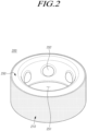
- FIG. 2 is a perspective view illustrating a ring-shaped (or, in other words, annular) wearable electronic device according to an embodiment of the disclosure.
- FIG. 3 is a perspective view illustrating an inside of a ring-shaped wearable electronic device according to an embodiment of the disclosure.
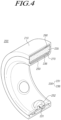
- FIG. 4 is a cross-sectional view illustrating a half part of a ring-shaped wearable electronic device according to an embodiment of the disclosure.
- a wearable electronic device 200 (e.g., the electronic device 101 of FIG. 1 ) according to an embodiment may overall have a ring shape to be detachable from the user's finger.
- the wearable electronic device 200 may be provided in a circular shape, but the disclosure is not limited thereto.
- the wearable electronic device 200 may include a frame 210 (which may also be described as: a support; a support portion, member, body, or component; an outer portion, member, body, or component; a perimeter or peripheral portion, member, body, or component; an outer housing; or an outer housing portion, member, body, or component), an electrical circuit part 230 (which may also be described as an electrical circuit portion, component, or module), a member 250 (which may also be described as: a molding member; a molded member; an inner member; an inner housing; or an inner housing portion, member, body, or component) , a compression member 270 (which may also be described as a compressible, or resilient, member, body, component, or element), and an adhesive member 290 (or adhesive body, component, or element).
- a frame 210 which may also be described as: a support; a support portion, member, body, or component; an outer portion, member, body, or component; a perimeter or peripheral portion, member, body, or component; an outer housing; or
- the wearable electronic device 200 may include a frame 210.
- the frame 210 may constitute the skeleton (or supporting framework, or support structure) of the wearable electronic device 200.
- the frame 210 may form an outer portion of the wearable electronic device 200.
- the frame 210 may be formed of a metal material.
- the frame 210 may be formed of a highly rigid titanium material, but the disclosure is not limited thereto.
- the frame may be annular.
- the wearable electronic device 200 may include a molding (or molded) member 250.
- the molding member 250 may be coupled to the frame 210 inside the frame 210 (specifically, the inner circumferential surface of the frame 210) to form the inner portion of the wearable electronic device 200.
- the frame 210 may be referred to as an outer ring member (or outer annular member)
- the molding member 250 may be referred to as an inner ring member (or inner annular member).
- the frame 210 and the molding member 250 form the outer portion and the inner portion, respectively, of the wearable electronic device 200, but the disclosure is not limited thereto.
- the frame 210 may form an inner portion of the wearable electronic device 200.
- the frame 210 may be referred to as an inner ring member, and the molding member 250 may be referred to as an outer ring member.
- a hole 251 into which the user's finger is inserted may be provided inside the molding member 250.
- the diameter of the hole 251 of the molding member 250 may be appropriately set according to the thickness of the user's finger.
- the wearable electronic device 200 may include an electrical circuit part 230.
- the electrical circuit part 230 may be positioned between the frame 210 and the molding member 250 (in other words, the electrical circuit portion 230 may be housed in a volume defined by the frame 210 and the member 250).
- each component of the electrical circuit part 230 may be disposed on the inner circumferential surface side of the frame 210.
- the electrical circuit part 230 may include one or more electronic elements configured to support various functions of the wearable electronic device 100.
- the electrical circuit part 230 may include at least one electronic component (e.g., the printed circuit board 236) electrically connected to the battery 235 to be described below.
- the electrical circuit part 230 may include a battery 235 for supplying power required for each electronic element of the wearable electronic device 200, and one or more printed circuit boards (PCBs) 236 on which various electronic elements configured to support various functions are disposed.
- PCBs printed circuit boards
- the battery 235 may be configured to supply power to each electronic element (or electronic component) provided in the wearable electronic device 200.
- the battery may power operation of the device 200.
- a connector 235a for electrical connection (or access) to the electronic component may be provided on one side of the battery 235.
- an escape space e.g., the escape space 235b of FIG. 7
- an electrode of the connector 235a may be formed in a portion of the battery 235 in which the connector 235a is provided.
- the battery 235 may include a supporting member 235c coupled to the battery 235 to cover the escape space 235b from the outside of the battery 235.
- the supporting member 235c may have a block shape as a whole. In this case, the supporting member 235c may be received in the escape space 235b.
- one surface (e.g., a surface facing the hole 251) of the supporting member 235c may contact one side portion 236a of the one or more printed circuit boards 236.
- the supporting member 235c may be formed of substantially the same material as the compression member 270. In an embodiment, the supporting member 235c may be formed of a flexible polyurethane foam, but the disclosure is not limited thereto.
- the supporting member 235c may be formed of, e.g., at least one of rubber (natural rubber or synthetic rubber), elastomer, chloroprene, silicone, or neoprene.
- the escape space 235b adjacent to the connector 235a of the battery 235 may be a substantially narrow space, and the battery 235 may not include a separate supporting member 235c as illustrated in FIG. 7 .
- the battery 235 may be implemented as a secondary battery capable of charging and discharging, but the disclosure is not limited thereto.
- the battery 235 may correspond to, e.g., a lithium ion battery.
- various electronic elements and electrical circuits including one or more sensors may be disposed on the one or more printed circuit boards 236.
- the one or more printed circuit boards 236 of the electrical circuit part 230 may include one or more flexible printed circuit boards (FPCBs) configured to be electrically connectable to the battery 235 inside the wearable electronic device 200 having a curved structure.
- the FPCB 236 may be electrically connected to the connector 235a of the battery 235, and power from the battery 235 may be supplied to various electronic components provided in the electrical circuit part 230 through the FPCB 236.
- the FPCB 236 may be provided with a charging circuit for wireless charging of the battery 235.
- the electrical circuit part 230 may include at least one sensor unit 231 for detecting the user's biometric signal. According to an embodiment, the electrical circuit part 230 may include various electronic components for various functions of the wearable electronic device 200 in addition to the one or more sensor units 231 for biometric signal detection.
- the electrical circuit part 230 may include various electronic components, such as a control module (e.g., the controller 232), a communication module (e.g., the communication unit 233), an audio module (not shown), a power module (e.g., the battery 235), and an input module (not shown).
- a control module e.g., the controller 232
- a communication module e.g., the communication unit 233
- an audio module not shown
- a power module e.g., the battery 235
- an input module not shown
- the battery 235 may be disposed on the side of one surface (e.g., the inner circumferential surface) of the frame 210.
- the battery 235 may be fixed to the inner circumferential surface of the frame 210 by a bonding method.
- the battery 235 may be attached to the inner circumferential surface of the frame 210 by the adhesive member 290 interposed between the battery 235 and the frame 210, but the disclosure is not limited thereto.
- the adhesive member 290 may include a tape having two opposite surfaces coated with an adhesive material (e.g., acrylic).
- the battery 235 may have a bent (or curved) shape.
- the battery 235 may be bent to have a curvature substantially corresponding to the curvature of the inner circumferential surface of the frame 210 to which the battery 235 is attached.
- the disclosure is not limited thereto.
- the molding member 250 may be coupled to the frame 210 to overall cover one surface (e.g., the inner circumferential surface of the frame 210) of the frame 210 and the electrical circuit part 230 and the battery 235 in the state in which the electrical circuit part 230 (e.g., the battery 235 and the PCB 236) is disposed on the side of the inner circumferential surface of the frame 210.
- the molding member 250 may be coupled with the frame 210 by at least one of an injection process or a molding process.
- the molding member 250 may be formed of a synthetic resin having a transparent material, but the disclosure is not limited thereto.
- the molding member 250 may be formed of, e.g., an epoxy resin.
- At least one biometric signal detector 252 protruding toward the inside of the hole 251, e.g., the center of the hole 251, may be provided on the inner circumferential surface of the molding member 250.
- the device 200 comprises at least one detector or sensor protruding, or extending, radially inwards from a surface of the inner portion of the device (which may, for example, be the molded member 250 or the frame 210, depending on the configuration of the device).
- the number of biometric signal detectors 252 may correspond to the number of sensor units 231 of the electric circuit part 230 described above, but the disclosure is not limited thereto.
- a corresponding sensor unit 231 may be positioned inside a plurality of biometric signal detectors 252.
- the plurality of biometric signal detectors 252 may contact the user's fingers, and may detect each of the user's body signals through the corresponding sensor unit 231.
- the wearable electronic device 200 may include a compression (or compressible) member 270 disposed adjacent to the battery 235.
- the compression member 270 may be disposed to contact at least one surface of the battery 235.
- the compression member 270 may be attached to at least one surface of the battery 235.
- the compression member 270 may be attached to an inner surface (e.g., a surface facing the inside of the hole 251, or, in other words, a surface facing radially inwards) of the battery 235.
- swelling i.e., volume expansion of the battery 235
- the compression member 270 disposed to contact at least one surface of the battery 235 may be configured to be compressible through contact with an expanding portion of the swollen battery 235 when the battery 235 swells.
- the compression member 270 may be gradually compressed more and more by the swollen portion.
- the compression member 270 may be formed of a flexible polyurethane foam, but the disclosure is not limited thereto.
- the compression member 270 may be formed of, e.g., at least one of rubber (natural rubber or synthetic rubber), elastomer, chloroprene, silicone, or neoprene.
- the compression member 270 may have a compression rate that is substantially the same as or higher than the volume expansion rate of the battery 235 that expands during battery swelling.
- the thickness of the compression member 270 may be set so that a value obtained by multiplying the thickness of the compression member 270 by the compression rate of the compression member 270 is equal to or greater than a value obtained by multiplying the thickness of the battery 235 by the volume expansion rate of the battery 235. In this case, the expanding portion due to swelling of the battery 235 may be received by the corresponding compression of the compression member 270. Due to the compression member 270, the pressure applied to the molding member 250 due to the volume expansion of the battery 235 may be reduced, and interference between the battery 235 and the molding member 250 may be reduced.
- the compressible member may be able to deform (compress) to accommodate an increase in battery volume (e.g. battery swelling), without deforming the molded member 250 and so without reducing the size (e.g. cross-sectional area) of the hole 251.
- battery volume e.g. battery swelling
- the size e.g. cross-sectional area
- two opposite surfaces of the compression member 270 may be coated with an adhesive material.
- the compression member 270 may be attached and fixed to each counterpart (e.g., the frame 210, the battery 235, or the PCB 236) contacting the compression member 270.
- two opposite surfaces of the compression member 270 may refer to a surface facing the center of the wearable electronic device 200 (e.g., the center of the hole 251 of the molding member 250) (in other words, a surface facing radially inwards) and a surface facing away from the center of the wearable electronic device 200 (in other words, a surface facing radially outwards).
- one surface of the compression member 270 may be fixedly disposed in contact with the battery 235 as described above, while the other surface may be fixedly disposed in contact with the PCB 236 (e.g., FPCB) of the electrical circuit part 230 as illustrated in FIGS. 3 and 4 .
- PCB 236 e.g., FPCB
- FIG. 5 is a functional block diagram illustrating a ring-shaped wearable electronic device according to an embodiment.
- FIG. 5 is a block diagram illustrating a state in which a sensor unit 231, a battery 235, and a communication unit 233 are electrically connected to a controller 232 according to an embodiment.
- the electrical circuit part 230 may include a sensor unit (or module) 231, a communication unit (or module) 233, a battery 235 (or battery unit, pack, or module), and a controller 232 (or control unit or module).
- the sensor unit 231 may be configured to perform various functions.
- the sensor unit 231 may perform a function of detecting whether the user has apnea during sleep, a function of detecting whether the user is asleep and a sleep stage, a function of measuring blood pressure, a function of measuring calorie consumption, a function of measuring skin hydration, a function of authenticating the user, and/or a function of measuring temperature, and a touch input function for controlling the device.
- the sensor unit 231 may include at least one of various sensors to perform the above-described various functions.
- the sensor unit 231 may include a photoplethysmography (PPG) sensor 2311 for detecting whether the user has apnea during sleep.
- PPG photoplethysmography
- the PPG sensor 2311 may measure the user's blood oxygen saturation to detect whether the user has apnea during sleep.
- the PPG sensor 2311 may include a light emitter (not shown) configured to emit light toward the user's finger when the user wears the wearable electronic device 200, and a light receiver (not shown) configured to receive light reflected from the blood vessel inside the user's finger among the light emitted from the light emitter.
- the light emitter may include at least one light source.
- the at least one light source may include at least one of a red light emitting diode (LED) or an infrared LED.
- the light receiver may include at least one photodiode.
- the sensor unit 231 may include a galvanic skin response sensor (GSR) 2312 for detecting a change in current due to moisture discharged from the user's finger skin.
- GSR galvanic skin response sensor
- the GSR sensor 2312 may be configured to detect a change in skin humidity due to the sympathetic nervous system of the body as a change in electrical resistance.
- the controller 232 may determine whether the current state of the user is an awakened state or a drowsy state based on the change in the resistance of the GSR sensor 2312 corresponding to the change in the skin humidity, and determine whether the user sleeps.
- the controller 232 may determine whether the user is drowsy by simultaneously measuring the skin impedance response (SIR) corresponding to the alternating current (AC) component and the overall skin impedance level (SIL) corresponding to the direct current (DC) component, using the signal of the GSR sensor 2312. Specifically, when the user is dozing off, the expression interval of the SIR becomes longer, the expression frequency decreases, and the SIL increases.
- SIR skin impedance response
- SIL overall skin impedance level
- the sensor unit 231 may include an electrocardiogram (ECG) sensor 2313.
- ECG electrocardiogram
- the ECG sensor 2313 may be configured to measure the user's heartrate and constantness.
- the ECG sensor 2313 may be used to check the size and position of the user's heart or whether the user's heart is damaged.
- the ECG sensor 2313 may be used to measure and diagnose an abnormal rhythm of the heart.
- the ECG sensor 2313 is effective in measuring an abnormal rhythm due to damage to conductive tissue that transmits an electrical signal.
- the sensor unit 231 may include an acceleration sensor 2314 for detecting the user's movement.
- the acceleration sensor 2314 may correspond to, e.g., a three-axis acceleration sensor that measures acceleration in the X-axis, Y-axis, and Z-axis directions.
- the acceleration sensor 2314 may be replaced by a gyro sensor (not shown) or may detect the user's movement in combination with the gyro sensor.
- the sensor unit 231 may include a temperature sensor 2315 for detecting the user's body temperature or an object's temperature.
- the temperature sensor 2315 may correspond to a contactless temperature sensor, but the disclosure is not limited thereto.
- the sensor unit 231 may include a fingerprint sensor 2316 for detecting the user's fingerprint.
- the fingerprint sensor 2316 may be implemented by, e.g., an optical fingerprint recognition method, a capacitive fingerprint recognition method, or an ultrasonic fingerprint recognition method, but the disclosure is not limited thereto.
- the controller 232 may be configured to perform the overall operation of the wearable electronic device 200.
- the controller 232 may measure the blood pressure of the user by using a known blood pressure estimation method based on the ECG signal detected by the ECG sensor 2313 and the blood oxygen saturation detected by the PPG sensor 2311.
- the controller 232 may measure the calorie consumption of the user based on the signal detected by the acceleration sensor 2314.
- the controller 232 may detect the sleep stage of the user by using the signal detected by the PPG sensor 2311 or the ECG sensor 2313 and the signal detected by the acceleration sensor 2314.
- the controller 232 may perform the user authentication function by using signals detected through the fingerprint sensor 2316 and the ECG sensor 2313. For example, the controller 232 may perform user authentication by comparing the detected fingerprint data and ECG data with the user's fingerprint data and ECG data previously stored in memory (not shown).
- the controller 232 may receive power from the battery 235 and may supply the received power to the sensor unit 231 or the communication unit 233.
- the communication unit 233 may be configured to transmit various signals detected by the sensor unit 231 to an external device (e.g., the electronic device 102 of FIG. 1 ) or to receive signals transmitted from the external device 102.
- an external device e.g., the electronic device 102 of FIG. 1
- the communication unit 233 may include an element that performs a wireless communication function of any one of Bluetooth, Wi-Fi, and Zigbee technologies.
- the communication unit 233 may include a near-field communication (NFC) chip for implementing a mobile payment function.
- NFC near-field communication
- the battery 235 may wirelessly receive power from an external wireless charging device (not shown) through the wireless charging circuit and be charged with the power.
- an external wireless charging device not shown
- the disclosure is not limited to this, and the battery 235 may be electrically connected to a separate external charger to be charged in a wired charging manner.
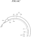
- FIGS. 6A to 6C are views schematically illustrating an arrangement structure of some components provided inside a ring-shaped wearable electronic device according to an embodiment of the disclosure.
- FIGS. 6A to 6C are views omitting the components corresponding to the molding member 250 and the frame 210 illustrated and described in connection with FIGS. 2 to 5 , for convenience of description, in describing the arrangement structure of the compression member 270.
- FIG. 6A is a view illustrating a state in which the compression member 270a is disposed to contact the inner surface (or radially inner surface) of the battery 235.
- FIG. 6B is a view illustrating a state in which the compression member 270b is disposed to contact the outer surface (or radially outer surface) of the battery 235.
- FIG. 6C is a view illustrating a state in which the compression members 270a and 270b are disposed to contact the inner surface and the outer surface, respectively, of the battery 235.
- the compression member 270a may be disposed on a radial inner surface (e.g., a surface close to the hole 251) of the battery 235.
- the inner surface of the battery 235 may refer to one surface of the battery 235 facing one or more FPCBs 236.
- the compression member 270a may be positioned between the one or more FPCBs 236 and the battery 235.
- the compression member 270a may extend along the inner surface of the battery 235. In an embodiment, the compression member 270a may be attached to a remaining area of the inner surface of the battery 235 except for an area to which the supporting member 235c is coupled. In an embodiment, the compression member 270a may include a partition 272 for dividing an area 270a1 where one side 236a of the one or more FPCBs 236 is attached and an area 270a2 where the other side 236b of the one or more FPCBs 236 is attached. In other words, the partition (or partition portion) 272 may separate area 270a1 from area 270a2.
- the partition 272 may be designed to be thicker than the areas 270a1 and 270a2 where one or more FPCBs 236 are attached.
- the partition 272 may protrude, or extend, from the radial inner surface (e.g., the surface close to the hole 251) of the compression member 270a (i.e. it may protrude or extend radially inwards).
- two opposite surfaces of the compression member 270a may contact at least a portion 236a and 236b of the one or more FPCBs 236 and the battery 235, respectively.
- two opposite radial side surfaces of the compression member 270a disposed in contact with the battery 235 and the one or more FPCBs 236, respectively, are surrounded by the battery 235 and the one or more FPCBs 236, respectively, not to be exposed to the outside. Accordingly, in the molding process for coupling the molding member 250 to the frame (e.g., the frame 210 of FIG. 3 ), the molding liquid does not penetrate two opposite radial side surfaces of the compression member 270a, and thus the compression performance of the compression member 270a may be maintained.
- the adhesive member 290a may be attached to the outer surface of the battery 235.
- the outer surface of the battery 235 is a surface opposite to the inner surface of the battery 235 described above and, although not specifically illustrated in the drawings, may refer to one surface of the battery 235 facing the frame (e.g., the frame 210 of FIG. 3 ).
- the battery 235 may be fixed to the inner circumferential surface of the frame 210 through the adhesive member 290a.
- the compression member 270b may be disposed on the radial outer surface of the battery 235, unlike that illustrated in FIG. 6A .
- the compression member 270b may be positioned between the battery 235 and the frame 210.
- the compression member 270b may extend along the outer surface of the battery 235.
- the compression member 270b may be entirely attached to the outer surface of the battery 235.
- two opposite surfaces of the compression member 270b may contact the battery 235 and the frame 210, respectively.
- two opposite radial side surfaces of the compression member 270b are surrounded by the battery 235 and the frame 210, respectively, not to be exposed to the outside. Accordingly, in the molding process for coupling the molding member 250 to the frame 210, the molding liquid does not penetrate two opposite radial side surfaces of the compression member 270b, and thus the compression performance of the compression member 270b may be maintained.
- the adhesive member 290b may be attached to the inner surface of the battery 235.
- at least portions 236a and 236b of the one or more FPCBs 236 disposed on the side of the inner surface of the battery 235 may be fixed to the battery 235 through the adhesive member 290b.
- the compression members 270a and 270b may be disposed on two opposite surfaces (e.g. on two opposite radial side surfaces), respectively, of the battery 235, unlike those illustrated in FIGS. 6A and 6B .
- the compression member 270 may include a first compression member 270a disposed on the radial inner surface of the battery 235 and a second compression member 270b disposed on the radial outer surface of the battery 235.
- the first compression member 270a may be positioned between the one or more FPCBs 236 and the battery 235.
- two opposite surfaces of the first compression member 270a may contact at least a portion of the one or more FPCBs 236 and the battery 235, respectively.
- two opposite radial side surfaces of the first compression member 270a are surrounded by the battery 235 and the one or more FPCBs 236, respectively, not to be exposed to the outside.
- the second compression member 270b may be positioned between the battery 235 and the frame 210, although not specifically illustrated. In an embodiment, two opposite surfaces of the second compression member 270b may contact the battery 235 and the frame 210, respectively. In this case, two opposite radial side surfaces of the second compression member 270b are surrounded by the battery 235 and the frame 210, respectively, not to be exposed to the outside in the radial direction.
- adhesive member 290a or 290b for coupling the battery 235 and the frame 210 or the battery 235 and one or more FPCBs 236, illustrated in FIGS. 6A and 6B may be replaced by the compression members 270a and 270b and, as the respective compression members 270a and 270b contact the two opposite radial sides of the battery 235, the compression member 270 may maximally absorb the expanding portion of the battery 235 during battery swelling.
- FIG. 7 is a perspective view illustrating an arrangement structure between some components provided inside a ring-shaped wearable electronic device according to an embodiment of the disclosure.
- a supporting member e.g., the supporting member 235c of FIG. 3
- one or more swelling holes 271 may be provided inside the compression member 270c according to an embodiment.
- the one or more swelling holes 271 may be provided in each of an area 270c1 where one side portion 236a of the one or more FPCBs 236 is attached and an area 270c2 where one side portion 236a of the one or more FPCBs 236 is attached.
- the compression member 270c may have a rectangular band shape as a whole (e.g. it may extend around a rectangular perimeter, with a void in the middle), but the disclosure is not limited thereto. In this case, when the swelling of the battery 235 occurs, the expanding portion of the battery 235, which is inflated according to the battery swelling, may be received in a space (or volume, or void) formed by the swelling hole 271 of the compression member 270c.
- the compression member 270c may also have a predetermined compression rate, like each of the compression members 270, 270a, and 270b described above with reference to FIGS. 2 to 4 or FIGS. 6A to 6C . Accordingly, in the compression member 270c, a portion of the remaining portion (e.g., the edge portion of the compression member 270c) other than the swelling hole 271, in which the molding liquid does not penetrate, has compression performance and may absorb the expanded battery volume during battery swelling.
- FIG. 8 is a view schematically illustrating a change in shape of a battery and a compression member when a battery swells in a ring-shaped wearable electronic device according to an embodiment of the disclosure.
- FIG. 8 is a view illustrating a state in which the compression member 270 is compressed by the battery 235 during swelling of the battery 235 when the compression member 270 is positioned between the battery 235 and the FPCB 236.
- FIG. 8(a) is a view illustrating a state of the battery 235 and the compression member 270 before the battery swells
- FIG. 8B is a view illustrating a state of the battery 235 and the compression member 270 after the battery swells.
- the electrolyte inside the battery 235 may vaporize and the battery 235 may swell due to the pressure. Specifically, when the battery 235 swells, as illustrated in FIG. 8(b) , the electrolyte inside the battery 235 is vaporized, so that the battery 235 may swell in the inner radial direction and/or the outer radial direction of the battery 235, thereby expanding the volume of the battery 235.
- the inside of the battery 235 swells due to the pressure of the vaporized electrolyte solution, expanding the overall volume of the battery 235.
- the compression member 270 attached to the battery 235 may be simultaneously compressed by the expanding portion of the battery 235.
- the compression member 270 is compressed by the amount corresponding to the expanded volume of the battery 235 during swelling, absorbing the expanded volume of the battery 235. Accordingly, the pressure applied by the expanded battery 235 to the molding member 250 adjacent to the battery 235 due to battery swelling may be reduced, thereby preventing cracks in the molding member 250 or reduction in the inner diameter of the wearable electronic device 200.
- FIG. 9 is a plan view illustrating a structure of a battery of a ring-shaped wearable electronic device according to an embodiment of the disclosure.
- a compression member 270' may be disposed inside a battery 235'.
- the battery 235' may include a battery housing 2351 forming an outer appearance of the battery 235', and a battery stack 2352 disposed inside the battery housing 2351 and in which a cathode, a separator, and an anode are sequentially and repeatedly stacked.
- the compression member 270' may be disposed inside the battery housing 2351 of the battery 235'. In an embodiment, the compression member 270' may be positioned between the battery housing 2351 and the battery stack 2352, inside the battery 235'. In an embodiment, the compression member 270' may be disposed adjacent to any one of outermost edges on two opposite sides of the battery stack 2352 in the stacking direction. In this case, when the battery 235' swells, the compression member 270' is compressed by the pressure of the electrolytic solution vaporized inside the battery, absorbing the volume expansion of the battery 235'.
- a wearable electronic device 200 may include a ring-shaped frame 210.
- the wearable electronic device 200 may include a battery 235 seated on (or over, or under, or supported by) the frame 210.
- the wearable electronic device 200 may include an electronic component 236 electrically connected to the battery 235.
- the wearable electronic device 200 may include a member 250 (e.g. a molding, or molded, member 250) coupled (or connected or attached) to the frame 210 to surround the battery 235 and the electronic component 236.
- the frame 210 and member 250 may, together, form a housing, and the battery 235 and electronic component 236 may be contained or encapsulated inside the housing (i.e.
- the frame 210 may be described as a first housing portion, part, or component, and the member 250 may be described as a second housing portion, part, or component.
- the wearable electronic device may include a compression member 270a, 270b, or 270c (or at least one compression member, or a plurality of compression members) disposed to contact the battery 235 (or, in other words, to be in contact with the battery).
- the compression member may be configured so that a part thereof, in contact with an expanding portion of the battery 235, is compressible when the battery 235 swells.
- the at least one compression member may be configured to be compressed by an expanding portion of the battery when the battery (235) swells.
- the compression member 270a, 270b, or 270c may be positioned between the frame 210 and the molding member 250.
- At least one compression member 270a, 270b, or 270c may be provided.
- the at least one compression member 270a, 270b, or 270c may be positioned in at least one of a space between the frame 210 and the battery 235 or a space between the battery 235 and the electronic component 236.
- the (or each) compression member 270a, 270b, or 270c may include a hole 271 configured to receive at least one expanding portion of the battery 235 when the battery 235 swells.
- a compression rate of the (or each) compression member 270a, 270b, or 270c may be substantially identical to or larger than an expansion rate of the battery 235 when the battery 235 swells.
- an adhesive material may be coated on two opposite surfaces of the (or each) compression member 270a, 270b, or 270c facing the electronic component 236 and the battery 235, respectively, or facing the frame 210 and the battery 235, respectively.
- the wearable electronic device 200 may further include an adhesive member 290a or 290b configured to attach the frame 210 and the battery 235 to each other or attach the battery 235 and the electronic component 236 to each other.
- the adhesive member 290a or 290b may be positioned in a space where the (or each) compression member 270a, 270b, or 270c is not positioned, of the space between the frame 210 and the battery 235 or the space between the battery 235 and the electronic component 236.
- the (or each) compression member 270a, 270b, or 270c may be (or may comprise, or may consist of) at least one of polyurethane foam, rubber, elastomer, chloroprene, silicone, or neoprene.
- the molding member 250 may be coupled to an inner circumferential surface of the frame 210 to configure an inner portion of the wearable electronic device 200.
- the molding member 250 may be coupled to an outer circumferential surface of the frame 210 to configure an outer portion of the wearable electronic device 200.
- the battery 235 may have a curvature substantially the same as a curvature of one surface of the frame 210 on which the battery 235 is mounted.
- a wearable electronic device 200 may include a ring-shaped frame 210.
- the wearable electronic device 200 may include a battery 235' seated on the frame 210.
- the wearable electronic device 200 may include an electronic component 236 electrically connected to the battery 235'.
- the wearable electronic device 200 may include a molding member 250 coupled to the frame 210 to surround the battery 235' and the electronic component 236.
- the wearable electronic device 200 may include a compression member 270' (or at least one compression member) disposed inside the battery 235' and configured to be compressible, for example to offset a pressure generated inside the battery 235' when the battery 235' swells (and/or prevent distortion of a battery housing when pressure increases inside the battery housing).
- the battery 235' may include a battery housing 2351 and a battery stack 2352 received inside the battery housing 2351.
- the compression member 270' may be positioned between the battery housing 2351 and the battery stack 2352 inside the battery 235'.
- an adhesive material may be coated on two opposite surfaces of the compression member 270' facing the battery housing 2351 and the battery stack 2352, respectively.
- a compression rate of the compression member 270' may be substantially identical to or larger than an expansion rate of the battery 235' when the battery 235' swells.
- the compression member 270' may be formed of at least one of polyurethane foam, rubber, elastomer, chloroprene, silicone, or neoprene.
- a wearable electronic device comprising electronic circuitry, a battery arranged to power the electronic circuitry (when in use), a housing defining an internal volume, and at least one compressible member, wherein the electronic circuitry, battery, and at least one compressible member are arranged in said internal volume, and the at least one compressible member is arranged between the battery and an internal surface of the housing so as to compress in response to an increase in volume or change of shape the battery and prevent said increase or change of shape from distorting the housing.
- a wearable electronic device comprising electronic circuitry, a battery arranged to power the electronic circuitry (when in use), and a housing defining an internal volume, wherein the electronic circuitry and battery are arranged in said internal volume, and the battery comprises a battery housing and at least one compressible member inside the battery housing.
- the compressible member may be arranged to compress and prevent distortion of the battery housing, for example in response to a change in at least one internal property, state, or condition of the battery (or of a component of the battery) and/or in response to a change in a shape, size, or volume of at least one internal component of the battery.
- the compressible member(s) inside the battery housing may thus prevent the change or changes from distorting the battery housing and so from distorting the housing of the wearable electronic device.
Landscapes
- Engineering & Computer Science (AREA)
- Health & Medical Sciences (AREA)
- Life Sciences & Earth Sciences (AREA)
- Physics & Mathematics (AREA)
- Theoretical Computer Science (AREA)
- General Engineering & Computer Science (AREA)
- Biophysics (AREA)
- General Health & Medical Sciences (AREA)
- Biomedical Technology (AREA)
- Computer Hardware Design (AREA)
- Human Computer Interaction (AREA)
- General Physics & Mathematics (AREA)
- Medical Informatics (AREA)
- Molecular Biology (AREA)
- Pathology (AREA)
- Public Health (AREA)
- Heart & Thoracic Surgery (AREA)
- Animal Behavior & Ethology (AREA)
- Veterinary Medicine (AREA)
- Surgery (AREA)
- Cardiology (AREA)
- General Chemical & Material Sciences (AREA)
- Chemical & Material Sciences (AREA)
- Electrochemistry (AREA)
- Chemical Kinetics & Catalysis (AREA)
- Power Engineering (AREA)
- Manufacturing & Machinery (AREA)
- Spectroscopy & Molecular Physics (AREA)
- Physiology (AREA)
- Optics & Photonics (AREA)
- Computer Networks & Wireless Communication (AREA)
- Dermatology (AREA)
- Neurology (AREA)
- Neurosurgery (AREA)
- Signal Processing (AREA)
- Battery Mounting, Suspending (AREA)
Abstract
Description
- Various embodiments of the disclosure relate to a wearable electronic device having a battery and a molding member surrounding a space around the battery.
- Wearable electronic devices are devices, such as clothes, watches, or glasses, which may be freely worn on the user's body. Wearable electronic devices may be classified into various types, such as smart glasses, smart watches, and ring-type wearable electronic devices (or smart rings), depending on their shape.
- Among wearable electronic devices, the ring-shaped wearable electronic device is worn on the user's body part (eg., a finger) through a ring formed therein. A smart ring may be able to detect the user's biometric signals through various sensors included therein when worn by the user, analyze the user's biometric signals detected, and provide the user with health information using analysis data, such as the user's pulse, sleep level, blood pressure, etc.
- A ring-shaped wearable electronic device may include a frame configuring the skeleton (or framework) of the wearable electronic device, a battery configured to supply power to electronic components provided in the wearable electronic device, and a molding member coupled to the frame to configure an outer portion or inner portion of the wearable electronic device.
- In an electronic device including a battery, the battery may swell due to a change in external environment, e.g., temperature and repeated use of the device. Such battery swelling may deform the structure of the electronic device. In particular, in an electronic device having at least a portion of the space around the battery, formed of a molding member, e.g., a ring-shaped wearable electronic device, battery swelling may damage the molding member due to volume expansion of the battery or reduce the inner diameter of the ring-shaped wearable electronic device, causing it difficult to pull out the user's finger.
- Various embodiments of the disclosure may provide a ring-shaped wearable electronic device including a compression member disposed near the battery to receive the volume expansion of the battery that occurs when the battery swells.
- According to an embodiment of the disclosure, a wearable electronic device may comprise a ring-shaped frame. The wearable electronic device may comprise a battery seated on the frame. The wearable electronic device may comprise an electronic component electrically connected to the battery. The wearable electronic device may comprise a molding member integrally coupled to the frame to surround the battery and the electronic component. The wearable electronic device may comprise a compression member disposed to contact the battery and configured so that a part thereof, in contact with an expanding portion of the battery, is compressible when the battery swells. The compression member may be positioned between the frame and the molding member.
- According to various embodiments of the disclosure, even when volume expansion occurs due to swelling of the battery, the compression member disposed near the battery may be compressed to receive the expanded volume of the battery, preventing damage to the product and human accidents.
- According to various embodiments of the disclosure, particularly for ring-shaped wearable electronic devices in which the space around the battery is filled with a molding member, product deformation and resultant accidents may be prevented by a compression member disposed near the battery to receive the expanded volume of the battery due to swelling.
- Effects of the disclosure are not limited to the foregoing, and other unmentioned effects would be apparent to one of ordinary skill in the art from the following description. In other words, unintended effects in practicing embodiments of the disclosure may also be derived by one of ordinary skill in the art from the embodiments of the disclosure.
- The above and other aspects, features, and advantages of certain embodiments of the disclosure will be more apparent from the following description taken in conjunction with the accompanying drawings, in which:
-
FIG. 1 is a view illustrating an electronic device in a network environment according to various embodiments; -
FIG. 2 is a perspective view illustrating a ring-shaped wearable electronic device according to an embodiment of the disclosure; -
FIG. 3 is a perspective view illustrating an inside of a ring-shaped wearable electronic device according to an embodiment of the disclosure; -
FIG. 4 is a cross-sectional view illustrating a half part of a ring-shaped wearable electronic device according to an embodiment of the disclosure; -
FIG. 5 is a functional block diagram illustrating a ring-shaped wearable electronic device according to an embodiment of the disclosure; -
FIG. 6A is a view schematically illustrating an arrangement structure of some components provided inside a ring-shaped wearable electronic device according to an embodiment of the disclosure; -
FIG. 6B is a view schematically illustrating an arrangement structure of some components provided inside a ring-shaped wearable electronic device according to an embodiment of the disclosure; -
FIG. 6C is a view schematically illustrating an arrangement structure of some components provided inside a ring-shaped wearable electronic device according to an embodiment of the disclosure; -
FIG. 7 is a perspective view illustrating an arrangement structure between some components provided inside a ring-shaped wearable electronic device according to an embodiment of the disclosure; -
FIG. 8 is a view schematically illustrating a change in volume of a battery and a compression member when a battery swells in a ring-shaped wearable electronic device according to an embodiment of the disclosure; and -
FIG. 9 is a plan view illustrating a structure of a battery of a ring-shaped wearable electronic device according to an embodiment of the disclosure. - It should be appreciated that various embodiments of the disclosure and the terms used therein are not intended to limit the technological features set forth herein to particular embodiments and include various changes, equivalents, or replacements for a corresponding embodiment.
- With regard to the description of the drawings, similar reference numerals may be used to refer to similar or related elements.
- It is to be understood that a singular form of a noun corresponding to an item may include one or more of the things, unless the relevant context clearly indicates otherwise.
- As used herein, each of such phrases as "A or B," "at least one of A and B," "at least one of A or B," "A, B, or C," "at least one of A, B, and C," and "at least one of A, B, or C," may include all possible combinations of the items enumerated together in a corresponding one of the phrases.
- As used herein, such terms as "1st" and "2nd," or "first" and "second" may be used to simply distinguish a corresponding component from another, and does not limit the components in other aspect (e.g., importance or order).
- It is to be understood that if an element (e.g., a first element) is referred to, with or without the term "operatively" or "communicatively", as "coupled with," "coupled to," "connected with," or "connected to" another element (e.g., a second element), it means that the element may be coupled with the other element directly (e.g., wiredly), wirelessly, or via a third element.
- It will be further understood that the terms "comprise" and/or "have," as used herein, specify the presence of stated features, integers, steps, operations, elements, and/or components, but do not preclude the presence or addition of one or more other features, integers, steps, operations, elements, components, and/or groups thereof.
- It will be understood that when a component is referred to as "connected to," "coupled to", "supported on," or "contacting" another component, the components may be connected to, coupled to, supported on, or contact each other directly or via a third component.
- Throughout the specification, when one component is positioned "on" another component, the first component may be positioned directly on the second component, or other component(s) may be positioned between the first and second component.
- The term "and/or" may denote a combination(s) of a plurality of related components as listed or any of the components.
- Hereinafter, the working principle and embodiments of the disclosure are described with reference to the accompanying drawings.
-
FIG. 1 is a block diagram illustrating anelectronic device 101 in anetwork environment 100 according to various embodiments. - Referring to
FIG. 1 , theelectronic device 101 in thenetwork environment 100 may communicate with at least one of anelectronic device 102 via a first network 198 (e.g., a short-range wireless communication network), or anelectronic device 104 or aserver 108 via a second network 199 (e.g., a long-range wireless communication network). According to an embodiment, theelectronic device 101 may communicate with theelectronic device 104 via theserver 108. According to an embodiment, theelectronic device 101 may include aprocessor 120,memory 130, aninput module 150, asound output module 155, adisplay module 160, anaudio module 170, asensor module 176, aninterface 177, aconnecting terminal 178, ahaptic module 179, acamera module 180, apower management module 188, abattery 189, acommunication module 190, a subscriber identification module (SIM) 196, or anantenna module 197. In an embodiment, at least one (e.g., the connecting terminal 178) of the components may be omitted from theelectronic device 101, or one or more other components may be added in theelectronic device 101. According to an embodiment, some (e.g., thesensor module 176, thecamera module 180, or the antenna module 197) of the components may be integrated into a single component (e.g., the display module 160). - The
processor 120 may execute, for example, software (e.g., a program 140) to control at least one other component (e.g., a hardware or software component) of theelectronic device 101 coupled with theprocessor 120, and may perform various data processing or computation. According to an embodiment, as at least part of the data processing or computation, theprocessor 120 may store a command or data received from another component (e.g., thesensor module 176 or the communication module 190) involatile memory 132, process the command or the data stored in thevolatile memory 132, and store resulting data innon-volatile memory 134. According to an embodiment, theprocessor 120 may include a main processor 121 (e.g., a central processing unit (CPU) or an application processor (AP)), or an auxiliary processor 123 (e.g., a graphics processing unit (GPU), a neural processing unit (NPU), an image signal processor (ISP), a sensor hub processor, or a communication processor (CP)) that is operable independently from, or in conjunction with, themain processor 121. For example, when theelectronic device 101 includes themain processor 121 and theauxiliary processor 123, theauxiliary processor 123 may be configured to use lower power than themain processor 121 or to be specified for a designated function. Theauxiliary processor 123 may be implemented as separate from, or as part of themain processor 121. - The
auxiliary processor 123 may control at least some of functions or states related to at least one component (e.g., thedisplay module 160, thesensor module 176, or the communication module 190) among the components of theelectronic device 101, instead of themain processor 121 while themain processor 121 is in an inactive (e.g., sleep) state, or together with themain processor 121 while themain processor 121 is in an active state (e.g., executing an application). According to an embodiment, the auxiliary processor 123 (e.g., an image signal processor or a communication processor) may be implemented as part of another component (e.g., thecamera module 180 or the communication module 190) functionally related to theauxiliary processor 123. According to an embodiment, the auxiliary processor 123 (e.g., the neural processing unit) may include a hardware structure specified for artificial intelligence model processing. The artificial intelligence model may be generated via machine learning. Such learning may be performed, e.g., by theelectronic device 101 where the artificial intelligence is performed or via a separate server (e.g., the server 108). Learning algorithms may include, but are not limited to, e.g., supervised learning, unsupervised learning, semi-supervised learning, or reinforcement learning. The artificial intelligence model may include a plurality of artificial neural network layers. The artificial neural network may be a deep neural network (DNN), a convolutional neural network (CNN), a recurrent neural network (RNN), a restricted Boltzmann machine (RBM), a deep belief network (DBN), a bidirectional recurrent deep neural network (BRDNN), deep Q-network or a combination of two or more thereof but is not limited thereto. The artificial intelligence model may, additionally or alternatively, include a software structure other than the hardware structure. - The
memory 130 may store various data used by at least one component (e.g., theprocessor 120 or the sensor module 176) of theelectronic device 101. The various data may include, for example, software (e.g., the program 140) and input data or output data for a command related thereto. Thememory 130 may include thevolatile memory 132 or thenon-volatile memory 134. - The
program 140 may be stored in thememory 130 as software, and may include, for example, an operating system (OS) 142,middleware 144, or anapplication 146. - The
input module 150 may receive a command or data to be used by other component (e.g., the processor 120) of theelectronic device 101, from the outside (e.g., a user) of theelectronic device 101. Theinput module 150 may include, for example, a microphone, a mouse, a keyboard, keys (e.g., buttons), or a digital pen (e.g., a stylus pen). - The
sound output module 155 may output sound signals to the outside of theelectronic device 101. Thesound output module 155 may include, for example, a speaker or a receiver. The speaker may be used for general purposes, such as playing multimedia or playing record. The receiver may be used for receiving incoming calls. According to an embodiment, the receiver may be implemented as separate from, or as part of the speaker. - The
display module 160 may visually provide information to the outside (e.g., a user) of theelectronic device 101. Thedisplay 160 may include, for example, a display, a hologram device, or a projector and control circuitry to control a corresponding one of the display, hologram device, and projector. According to an embodiment, thedisplay 160 may include a touch sensor configured to detect a touch, or a pressure sensor configured to measure the intensity of a force generated by the touch. - The
audio module 170 may convert a sound into an electrical signal and vice versa. According to an embodiment, theaudio module 170 may obtain the sound via theinput module 150, or output the sound via thesound output module 155 or a headphone of an external electronic device (e.g., an electronic device 102) directly (e.g., wiredly) or wirelessly coupled with theelectronic device 101. - The
sensor module 176 may detect an operational state (e.g., power or temperature) of theelectronic device 101 or an environmental state (e.g., a state of a user) external to theelectronic device 101, and then generate an electrical signal or data value corresponding to the detected state. According to an embodiment, thesensor module 176 may include, for example, a gesture sensor, a gyro sensor, an atmospheric pressure sensor, a magnetic sensor, an accelerometer, a grip sensor, a proximity sensor, a color sensor, an infrared (IR) sensor, a biometric sensor, a temperature sensor, a humidity sensor, or an illuminance sensor. - The
interface 177 may support one or more specified protocols to be used for theelectronic device 101 to be coupled with the external electronic device (e.g., the electronic device 102) directly (e.g., wiredly) or wirelessly. According to an embodiment, theinterface 177 may include, for example, a high definition multimedia interface (HDMI), a universal serial bus (USB) interface, a secure digital (SD) card interface, or an audio interface. - A connecting
terminal 178 may include a connector via which theelectronic device 101 may be physically connected with the external electronic device (e.g., the electronic device 102). According to an embodiment, the connectingterminal 178 may include, for example, a HDMI connector, a USB connector, a SD card connector, or an audio connector (e.g., a headphone connector). - The
haptic module 179 may convert an electrical signal into a mechanical stimulus (e.g., a vibration or motion) or electrical stimulus which may be recognized by a user via his tactile sensation or kinesthetic sensation. According to an embodiment, thehaptic module 179 may include, for example, a motor, a piezoelectric element, or an electric stimulator. - The
camera module 180 may capture a still image or moving images. According to an embodiment, thecamera module 180 may include one or more lenses, image sensors, image signal processors, or flashes. - The
power management module 188 may manage power supplied to theelectronic device 101. According to an embodiment, thepower management module 188 may be implemented as at least part of, for example, a power management integrated circuit (PMIC). - The
battery 189 may supply power to at least one component of theelectronic device 101. According to an embodiment, thebattery 189 may include, for example, a primary cell which is not rechargeable, a secondary cell which is rechargeable, or a fuel cell. - The
communication module 190 may support establishing a direct (e.g., wired) communication channel or a wireless communication channel between theelectronic device 101 and the external electronic device (e.g., theelectronic device 102, theelectronic device 104, or the server 108) and performing communication via the established communication channel. Thecommunication module 190 may include one or more communication processors that are operable independently from the processor 120 (e.g., the application processor (AP)) and supports a direct (e.g., wired) communication or a wireless communication. According to an embodiment, thecommunication module 190 may include a wireless communication module 192 (e.g., a cellular communication module, a short-range wireless communication module, or a global navigation satellite system (GNSS) communication module) or a wired communication module 194 (e.g., a local area network (LAN) communication module or a power line communication (PLC) module). A corresponding one of these communication modules may communicate with the externalelectronic device 104 via a first network 198 (e.g., a short-range communication network, such as Bluetooth™, wireless-fidelity (Wi-Fi) direct, or infrared data association (IrDA)) or a second network 199 (e.g., a long-range communication network, such as a legacy cellular network, a 5G network, a next-generation communication network, the Internet, or a computer network (e.g., local area network (LAN) or wide area network (WAN)). These various types of communication modules may be implemented as a single component (e.g., a single chip), or may be implemented as multi components (e.g., multi chips) separate from each other. The wireless communication module 192 may identify or authenticate theelectronic device 101 in a communication network, such as thefirst network 198 or thesecond network 199, using subscriber information (e.g., international mobile subscriber identity (IMSI)) stored in thesubscriber identification module 196. - The wireless communication module 192 may support a 5G network, after a 4G network, and next-generation communication technology, e.g., new radio (NR) access technology. The NR access technology may support enhanced mobile broadband (eMBB), massive machine type communications (mMTC), or ultra-reliable and low-latency communications (URLLC). The wireless communication module 192 may support a high-frequency band (e.g., the mmWave band) to achieve, e.g., a high data transmission rate. The wireless communication module 192 may support various technologies for securing performance on a high-frequency band, such as, e.g., beamforming, massive multiple-input and multiple-output (massive MIMO), full dimensional MIMO (FD-MIMO), array antenna, analog beam-forming, or large scale antenna. The wireless communication module 192 may support various requirements specified in the
electronic device 101, an external electronic device (e.g., the electronic device 104), or a network system (e.g., the second network 199). According to an embodiment, the wireless communication module 192 may support a peak data rate (e.g., 20Gbps or more) for implementing eMBB, loss coverage (e.g., 164dB or less) for implementing mMTC, or U-plane latency (e.g., 0.5ms or less for each of downlink (DL) and uplink (UL), or a round trip of 1ms or less) for implementing URLLC. - The
antenna module 197 may transmit or receive a signal or power to or from the outside (e.g., the external electronic device). According to an embodiment, theantenna module 197 may include one antenna including a radiator formed of a conductive body or conductive pattern formed on a substrate (e.g., a printed circuit board (PCB)). According to an embodiment, theantenna module 197 may include a plurality of antennas (e.g., an antenna array). In this case, at least one antenna appropriate for a communication scheme used in a communication network, such as thefirst network 198 or thesecond network 199, may be selected from the plurality of antennas by, e.g., thecommunication module 190. The signal or the power may then be transmitted or received between thecommunication module 190 and the external electronic device via the selected at least one antenna. According to an embodiment, other parts (e.g., radio frequency integrated circuit (RFIC)) than the radiator may be further formed as part of theantenna module 197. - According to various embodiments, the
antenna module 197 may form a mmWave antenna module. According to an embodiment, the mmWave antenna module may include a printed circuit board, a RFIC disposed on a first surface (e.g., the bottom surface) of the printed circuit board, or adjacent to the first surface and capable of supporting a designated high-frequency band (e.g., the mmWave band), and a plurality of antennas (e.g., array antennas) disposed on a second surface (e.g., the top or a side surface) of the printed circuit board, or adjacent to the second surface and capable of transmitting or receiving signals of the designated high-frequency band. - At least some of the above-described components may be coupled mutually and communicate signals (e.g., commands or data) therebetween via an inter-peripheral communication scheme (e.g., a bus, general purpose input and output (GPIO), serial peripheral interface (SPI), or mobile industry processor interface (MIPI)).
- According to an embodiment, commands or data may be transmitted or received between the
electronic device 101 and the externalelectronic device 104 via theserver 108 coupled with thesecond network 199. The externalelectronic devices electronic device 101. According to an embodiment, all or some of operations to be executed at theelectronic device 101 may be executed at one or more of the externalelectronic devices electronic device 101 should perform a function or a service automatically, or in response to a request from a user or another device, theelectronic device 101, instead of, or in addition to, executing the function or the service, may request the one or more external electronic devices to perform at least part of the function or the service. The one or more external electronic devices receiving the request may perform the at least part of the function or the service requested, or an additional function or an additional service related to the request, and transfer an outcome of the performing to theelectronic device 101. Theelectronic device 101 may provide the outcome, with or without further processing of the outcome, as at least part of a reply to the request. To that end, a cloud computing, distributed computing, mobile edge computing (MEC), or client-server computing technology may be used, for example. Theelectronic device 101 may provide ultra-low-latency services using, e.g., distributed computing or mobile edge computing. In another embodiment, the externalelectronic device 104 may include an Internet-of-things (IoT) device. Theserver 108 may be an intelligent server using machine learning and/or a neural network. According to an embodiment, the externalelectronic device 104 or theserver 108 may be included in thesecond network 199. Theelectronic device 101 may be applied to intelligent services (e.g., smart home, smart city, smart car, or health-care) based on 5G communication technology or IoT-related technology. - The electronic device according to various embodiments of the disclosure may be one of various types of electronic devices. The electronic devices may include, for example, a portable communication device (e.g., a smartphone), a computer device, a portable multimedia device, a portable medical device, a camera, a wearable device, or a home appliance. According to an embodiment of the disclosure, the electronic devices are not limited to those described above.
- The following description focuses primarily on a ring-shaped wearable electronic device according to embodiments of the disclosure, but the disclosure is not limited thereto. Various embodiments of the disclosure may be applied to electronic devices of various configurations and types, including ring-shaped wearable devices.
- In an embodiment, the ring-shaped wearable electronic device of the disclosure may detect the user's biometric signals through various sensors. In some embodiments, the ring-shaped wearable electronic device may analyze the detected biometric signal and may wirelessly transmit analysis data such as pulse, sleep level, blood pressure, or the like to a preset external device (e.g., user equipment having a display, a monitor, a TV, or the like) to provide the analysis data in the form of a text, a number, or an image to the user. Further, in some embodiments, the ring-shaped wearable electronic device according to the disclosure may separately include a display, and in this case, the analysis data in the form of a text, a number, or an image may be provided to the user through the display.
- Hereinafter, a configuration of a ring-shaped wearable electronic device according to an embodiment of the disclosure is described in detail with reference to the accompanying drawings.
-
FIG. 2 is a perspective view illustrating a ring-shaped (or, in other words, annular) wearable electronic device according to an embodiment of the disclosure.FIG. 3 is a perspective view illustrating an inside of a ring-shaped wearable electronic device according to an embodiment of the disclosure.FIG. 4 is a cross-sectional view illustrating a half part of a ring-shaped wearable electronic device according to an embodiment of the disclosure. - Referring to
FIGS. 2 to 4 , a wearable electronic device 200 (e.g., theelectronic device 101 ofFIG. 1 ) according to an embodiment may overall have a ring shape to be detachable from the user's finger. For example, the wearableelectronic device 200 may be provided in a circular shape, but the disclosure is not limited thereto. - According to an embodiment, the wearable
electronic device 200 may include a frame 210 (which may also be described as: a support; a support portion, member, body, or component; an outer portion, member, body, or component; a perimeter or peripheral portion, member, body, or component; an outer housing; or an outer housing portion, member, body, or component), an electrical circuit part 230 (which may also be described as an electrical circuit portion, component, or module), a member 250 (which may also be described as: a molding member; a molded member; an inner member; an inner housing; or an inner housing portion, member, body, or component) , a compression member 270 (which may also be described as a compressible, or resilient, member, body, component, or element), and an adhesive member 290 (or adhesive body, component, or element). - According to an embodiment, the wearable
electronic device 200 may include aframe 210. According to an embodiment, theframe 210 may constitute the skeleton (or supporting framework, or support structure) of the wearableelectronic device 200. According to an embodiment, theframe 210 may form an outer portion of the wearableelectronic device 200. In an embodiment, theframe 210 may be formed of a metal material. For example, theframe 210 may be formed of a highly rigid titanium material, but the disclosure is not limited thereto. The frame may be annular. - According to an embodiment, the wearable
electronic device 200 may include a molding (or molded)member 250. According to an embodiment, e.g., as illustrated inFIG. 2 , themolding member 250 may be coupled to theframe 210 inside the frame 210 (specifically, the inner circumferential surface of the frame 210) to form the inner portion of the wearableelectronic device 200. In this case, theframe 210 may be referred to as an outer ring member (or outer annular member), and themolding member 250 may be referred to as an inner ring member (or inner annular member). - With reference to
FIGS. 2 to 4 , it is illustrated and described that theframe 210 and themolding member 250 form the outer portion and the inner portion, respectively, of the wearableelectronic device 200, but the disclosure is not limited thereto. According to another embodiment of the disclosure, theframe 210 may form an inner portion of the wearableelectronic device 200. For example, unlike that illustrated inFIG. 2 , when themolding member 250 is coupled to theframe 210 outside the frame 210 (specifically, the outer circumferential surface of the frame 210), theframe 210 may form an inner portion of the wearable electronic device. In this case, theframe 210 may be referred to as an inner ring member, and themolding member 250 may be referred to as an outer ring member. - In an embodiment, as illustrated in
FIG. 2 , ahole 251 into which the user's finger is inserted may be provided inside themolding member 250. In an embodiment, the diameter of thehole 251 of themolding member 250 may be appropriately set according to the thickness of the user's finger. - According to an embodiment, the wearable
electronic device 200 may include anelectrical circuit part 230. In an embodiment, theelectrical circuit part 230 may be positioned between theframe 210 and the molding member 250 (in other words, theelectrical circuit portion 230 may be housed in a volume defined by theframe 210 and the member 250). According to an embodiment, each component of theelectrical circuit part 230 may be disposed on the inner circumferential surface side of theframe 210. According to an embodiment, theelectrical circuit part 230 may include one or more electronic elements configured to support various functions of the wearableelectronic device 100. According to an embodiment, theelectrical circuit part 230 may include at least one electronic component (e.g., the printed circuit board 236) electrically connected to thebattery 235 to be described below. - According to an embodiment, the
electrical circuit part 230 may include abattery 235 for supplying power required for each electronic element of the wearableelectronic device 200, and one or more printed circuit boards (PCBs) 236 on which various electronic elements configured to support various functions are disposed. - According to an embodiment, the
battery 235 may be configured to supply power to each electronic element (or electronic component) provided in the wearableelectronic device 200. In other words, the battery may power operation of thedevice 200. - In an embodiment, a
connector 235a for electrical connection (or access) to the electronic component (e.g., the printed circuit board 236) may be provided on one side of thebattery 235. In an embodiment, an escape space (e.g., theescape space 235b ofFIG. 7 ) for extending an electrode of theconnector 235a may be formed in a portion of thebattery 235 in which theconnector 235a is provided. - In an embodiment, the
battery 235 may include a supportingmember 235c coupled to thebattery 235 to cover theescape space 235b from the outside of thebattery 235. In an embodiment, the supportingmember 235c may have a block shape as a whole. In this case, the supportingmember 235c may be received in theescape space 235b. - In an embodiment, one surface (e.g., a surface facing the hole 251) of the supporting
member 235c may contact oneside portion 236a of the one or more printedcircuit boards 236. - In an embodiment, the supporting
member 235c may be formed of substantially the same material as thecompression member 270. In an embodiment, the supportingmember 235c may be formed of a flexible polyurethane foam, but the disclosure is not limited thereto. The supportingmember 235c may be formed of, e.g., at least one of rubber (natural rubber or synthetic rubber), elastomer, chloroprene, silicone, or neoprene. - In an embodiment, the
escape space 235b adjacent to theconnector 235a of thebattery 235 may be a substantially narrow space, and thebattery 235 may not include a separate supportingmember 235c as illustrated inFIG. 7 . - In an embodiment, the
battery 235 may be implemented as a secondary battery capable of charging and discharging, but the disclosure is not limited thereto. Thebattery 235 may correspond to, e.g., a lithium ion battery. - In an embodiment, various electronic elements and electrical circuits including one or more sensors may be disposed on the one or more printed
circuit boards 236. According to an embodiment, the one or more printedcircuit boards 236 of theelectrical circuit part 230 may include one or more flexible printed circuit boards (FPCBs) configured to be electrically connectable to thebattery 235 inside the wearableelectronic device 200 having a curved structure. For example, theFPCB 236 may be electrically connected to theconnector 235a of thebattery 235, and power from thebattery 235 may be supplied to various electronic components provided in theelectrical circuit part 230 through theFPCB 236. In an embodiment, theFPCB 236 may be provided with a charging circuit for wireless charging of thebattery 235. - According to an embodiment, the
electrical circuit part 230 may include at least onesensor unit 231 for detecting the user's biometric signal. According to an embodiment, theelectrical circuit part 230 may include various electronic components for various functions of the wearableelectronic device 200 in addition to the one ormore sensor units 231 for biometric signal detection. Theelectrical circuit part 230 may include various electronic components, such as a control module (e.g., the controller 232), a communication module (e.g., the communication unit 233), an audio module (not shown), a power module (e.g., the battery 235), and an input module (not shown). The configuration of theelectrical circuit part 230 is described below in more detail with reference toFIG. 5 . - According to an embodiment, the
battery 235 may be disposed on the side of one surface (e.g., the inner circumferential surface) of theframe 210. In an embodiment, thebattery 235 may be fixed to the inner circumferential surface of theframe 210 by a bonding method. In an embodiment, thebattery 235 may be attached to the inner circumferential surface of theframe 210 by theadhesive member 290 interposed between thebattery 235 and theframe 210, but the disclosure is not limited thereto. In an embodiment, theadhesive member 290 may include a tape having two opposite surfaces coated with an adhesive material (e.g., acrylic). - According to an embodiment, the
battery 235 may have a bent (or curved) shape. In an embodiment, thebattery 235 may be bent to have a curvature substantially corresponding to the curvature of the inner circumferential surface of theframe 210 to which thebattery 235 is attached. However, the disclosure is not limited thereto. - According to an embodiment, the
molding member 250 may be coupled to theframe 210 to overall cover one surface (e.g., the inner circumferential surface of the frame 210) of theframe 210 and theelectrical circuit part 230 and thebattery 235 in the state in which the electrical circuit part 230 (e.g., thebattery 235 and the PCB 236) is disposed on the side of the inner circumferential surface of theframe 210. In an embodiment, themolding member 250 may be coupled with theframe 210 by at least one of an injection process or a molding process. In an embodiment, themolding member 250 may be formed of a synthetic resin having a transparent material, but the disclosure is not limited thereto. Themolding member 250 may be formed of, e.g., an epoxy resin. - According to an embodiment, at least one
biometric signal detector 252 protruding toward the inside of thehole 251, e.g., the center of thehole 251, may be provided on the inner circumferential surface of themolding member 250. In other words, in certain embodiments, thedevice 200 comprises at least one detector or sensor protruding, or extending, radially inwards from a surface of the inner portion of the device (which may, for example, be the moldedmember 250 or theframe 210, depending on the configuration of the device). In an embodiment, the number ofbiometric signal detectors 252 may correspond to the number ofsensor units 231 of theelectric circuit part 230 described above, but the disclosure is not limited thereto. In an embodiment, a correspondingsensor unit 231 may be positioned inside a plurality ofbiometric signal detectors 252. In this case, when the user wears the wearableelectronic device 200, the plurality ofbiometric signal detectors 252, respectively, may contact the user's fingers, and may detect each of the user's body signals through the correspondingsensor unit 231. - According to an embodiment, the wearable
electronic device 200 may include a compression (or compressible)member 270 disposed adjacent to thebattery 235. In an embodiment, thecompression member 270 may be disposed to contact at least one surface of thebattery 235. In an embodiment, thecompression member 270 may be attached to at least one surface of thebattery 235. For example, as illustrated inFIGS. 3 and4 , thecompression member 270 may be attached to an inner surface (e.g., a surface facing the inside of thehole 251, or, in other words, a surface facing radially inwards) of thebattery 235. - According to an embodiment, swelling, i.e., volume expansion of the
battery 235, may occur in thebattery 235 of the wearableelectronic device 200 as the internal electrolyte vaporizes due to changes in the external environment such as temperature, and repeated use. According to an embodiment, thecompression member 270 disposed to contact at least one surface of thebattery 235 may be configured to be compressible through contact with an expanding portion of theswollen battery 235 when thebattery 235 swells. In an embodiment, when thebattery 235 gradually swells more and more, thecompression member 270 may be gradually compressed more and more by the swollen portion. - In an embodiment, the
compression member 270 may be formed of a flexible polyurethane foam, but the disclosure is not limited thereto. Thecompression member 270 may be formed of, e.g., at least one of rubber (natural rubber or synthetic rubber), elastomer, chloroprene, silicone, or neoprene. - In an embodiment, the
compression member 270 may have a compression rate that is substantially the same as or higher than the volume expansion rate of thebattery 235 that expands during battery swelling. In an embodiment, the thickness of thecompression member 270 may be set so that a value obtained by multiplying the thickness of thecompression member 270 by the compression rate of thecompression member 270 is equal to or greater than a value obtained by multiplying the thickness of thebattery 235 by the volume expansion rate of thebattery 235. In this case, the expanding portion due to swelling of thebattery 235 may be received by the corresponding compression of thecompression member 270. Due to thecompression member 270, the pressure applied to themolding member 250 due to the volume expansion of thebattery 235 may be reduced, and interference between thebattery 235 and themolding member 250 may be reduced. In other words, the compressible member may be able to deform (compress) to accommodate an increase in battery volume (e.g. battery swelling), without deforming the moldedmember 250 and so without reducing the size (e.g. cross-sectional area) of thehole 251. - In an embodiment, two opposite surfaces of the
compression member 270 may be coated with an adhesive material. In this case, thecompression member 270 may be attached and fixed to each counterpart (e.g., theframe 210, thebattery 235, or the PCB 236) contacting thecompression member 270. Here, two opposite surfaces of thecompression member 270 may refer to a surface facing the center of the wearable electronic device 200 (e.g., the center of thehole 251 of the molding member 250) (in other words, a surface facing radially inwards) and a surface facing away from the center of the wearable electronic device 200 (in other words, a surface facing radially outwards). According to an embodiment, one surface of thecompression member 270 may be fixedly disposed in contact with thebattery 235 as described above, while the other surface may be fixedly disposed in contact with the PCB 236 (e.g., FPCB) of theelectrical circuit part 230 as illustrated inFIGS. 3 and4 . -
FIG. 5 is a functional block diagram illustrating a ring-shaped wearable electronic device according to an embodiment. -
FIG. 5 is a block diagram illustrating a state in which asensor unit 231, abattery 235, and acommunication unit 233 are electrically connected to acontroller 232 according to an embodiment. - Referring to
FIG. 5 , theelectrical circuit part 230 according to an embodiment may include a sensor unit (or module) 231, a communication unit (or module) 233, a battery 235 (or battery unit, pack, or module), and a controller 232 (or control unit or module). - According to an embodiment, the
sensor unit 231 may be configured to perform various functions. In an embodiment, thesensor unit 231 may perform a function of detecting whether the user has apnea during sleep, a function of detecting whether the user is asleep and a sleep stage, a function of measuring blood pressure, a function of measuring calorie consumption, a function of measuring skin hydration, a function of authenticating the user, and/or a function of measuring temperature, and a touch input function for controlling the device. In an embodiment, thesensor unit 231 may include at least one of various sensors to perform the above-described various functions. - According to an embodiment, the
sensor unit 231 may include a photoplethysmography (PPG)sensor 2311 for detecting whether the user has apnea during sleep. In an embodiment, thePPG sensor 2311 may measure the user's blood oxygen saturation to detect whether the user has apnea during sleep. - According to an embodiment, the
PPG sensor 2311 may include a light emitter (not shown) configured to emit light toward the user's finger when the user wears the wearableelectronic device 200, and a light receiver (not shown) configured to receive light reflected from the blood vessel inside the user's finger among the light emitted from the light emitter. In an embodiment, the light emitter may include at least one light source. For example, the at least one light source may include at least one of a red light emitting diode (LED) or an infrared LED. In an embodiment, the light receiver may include at least one photodiode. - According to an embodiment, the
sensor unit 231 may include a galvanic skin response sensor (GSR) 2312 for detecting a change in current due to moisture discharged from the user's finger skin. In an embodiment, theGSR sensor 2312 may be configured to detect a change in skin humidity due to the sympathetic nervous system of the body as a change in electrical resistance. In this case, thecontroller 232 may determine whether the current state of the user is an awakened state or a drowsy state based on the change in the resistance of theGSR sensor 2312 corresponding to the change in the skin humidity, and determine whether the user sleeps. For example, thecontroller 232 may determine whether the user is drowsy by simultaneously measuring the skin impedance response (SIR) corresponding to the alternating current (AC) component and the overall skin impedance level (SIL) corresponding to the direct current (DC) component, using the signal of theGSR sensor 2312. Specifically, when the user is dozing off, the expression interval of the SIR becomes longer, the expression frequency decreases, and the SIL increases. - According to an embodiment, the
sensor unit 231 may include an electrocardiogram (ECG)sensor 2313. In an embodiment, theECG sensor 2313 may be configured to measure the user's heartrate and constantness. In an embodiment, theECG sensor 2313 may be used to check the size and position of the user's heart or whether the user's heart is damaged. For example, theECG sensor 2313 may be used to measure and diagnose an abnormal rhythm of the heart. In particular, theECG sensor 2313 is effective in measuring an abnormal rhythm due to damage to conductive tissue that transmits an electrical signal. - According to an embodiment, the
sensor unit 231 may include anacceleration sensor 2314 for detecting the user's movement. Theacceleration sensor 2314 may correspond to, e.g., a three-axis acceleration sensor that measures acceleration in the X-axis, Y-axis, and Z-axis directions. In an embodiment, theacceleration sensor 2314 may be replaced by a gyro sensor (not shown) or may detect the user's movement in combination with the gyro sensor. - According to an embodiment, the
sensor unit 231 may include atemperature sensor 2315 for detecting the user's body temperature or an object's temperature. In an embodiment, thetemperature sensor 2315 may correspond to a contactless temperature sensor, but the disclosure is not limited thereto. - According to an embodiment, the
sensor unit 231 may include afingerprint sensor 2316 for detecting the user's fingerprint. Thefingerprint sensor 2316 may be implemented by, e.g., an optical fingerprint recognition method, a capacitive fingerprint recognition method, or an ultrasonic fingerprint recognition method, but the disclosure is not limited thereto. - According to an embodiment, the
controller 232 may be configured to perform the overall operation of the wearableelectronic device 200. - In an embodiment, the
controller 232 may measure the blood pressure of the user by using a known blood pressure estimation method based on the ECG signal detected by theECG sensor 2313 and the blood oxygen saturation detected by thePPG sensor 2311. - In an embodiment, the
controller 232 may measure the calorie consumption of the user based on the signal detected by theacceleration sensor 2314. - In an embodiment, the
controller 232 may detect the sleep stage of the user by using the signal detected by thePPG sensor 2311 or theECG sensor 2313 and the signal detected by theacceleration sensor 2314. - In an embodiment, the
controller 232 may perform the user authentication function by using signals detected through thefingerprint sensor 2316 and theECG sensor 2313. For example, thecontroller 232 may perform user authentication by comparing the detected fingerprint data and ECG data with the user's fingerprint data and ECG data previously stored in memory (not shown). - In an embodiment, the
controller 232 may receive power from thebattery 235 and may supply the received power to thesensor unit 231 or thecommunication unit 233. - According to an embodiment, the
communication unit 233 may be configured to transmit various signals detected by thesensor unit 231 to an external device (e.g., theelectronic device 102 ofFIG. 1 ) or to receive signals transmitted from theexternal device 102. - According to an embodiment, the
communication unit 233 may include an element that performs a wireless communication function of any one of Bluetooth, Wi-Fi, and Zigbee technologies. In an embodiment, thecommunication unit 233 may include a near-field communication (NFC) chip for implementing a mobile payment function. - According to an embodiment, the
battery 235 may wirelessly receive power from an external wireless charging device (not shown) through the wireless charging circuit and be charged with the power. However, the disclosure is not limited to this, and thebattery 235 may be electrically connected to a separate external charger to be charged in a wired charging manner. -
FIGS. 6A to 6C are views schematically illustrating an arrangement structure of some components provided inside a ring-shaped wearable electronic device according to an embodiment of the disclosure. -
FIGS. 6A to 6C are views omitting the components corresponding to themolding member 250 and theframe 210 illustrated and described in connection withFIGS. 2 to 5 , for convenience of description, in describing the arrangement structure of thecompression member 270. - Specifically, referring to
FIGS. 6A to 6C ,FIG. 6A is a view illustrating a state in which thecompression member 270a is disposed to contact the inner surface (or radially inner surface) of thebattery 235.FIG. 6B is a view illustrating a state in which thecompression member 270b is disposed to contact the outer surface (or radially outer surface) of thebattery 235.FIG. 6C is a view illustrating a state in which thecompression members battery 235. - Referring to
FIG. 6A , thecompression member 270a according to an embodiment may be disposed on a radial inner surface (e.g., a surface close to the hole 251) of thebattery 235. Here, the inner surface of thebattery 235 may refer to one surface of thebattery 235 facing one ormore FPCBs 236. In an embodiment, thecompression member 270a may be positioned between the one or more FPCBs 236 and thebattery 235. - According to an embodiment, the
compression member 270a may extend along the inner surface of thebattery 235. In an embodiment, thecompression member 270a may be attached to a remaining area of the inner surface of thebattery 235 except for an area to which the supportingmember 235c is coupled. In an embodiment, thecompression member 270a may include apartition 272 for dividing an area 270a1 where oneside 236a of the one ormore FPCBs 236 is attached and an area 270a2 where theother side 236b of the one ormore FPCBs 236 is attached. In other words, the partition (or partition portion) 272 may separate area 270a1 from area 270a2. In an embodiment, thepartition 272 may be designed to be thicker than the areas 270a1 and 270a2 where one or more FPCBs 236 are attached. In an embodiment, thepartition 272 may protrude, or extend, from the radial inner surface (e.g., the surface close to the hole 251) of thecompression member 270a (i.e. it may protrude or extend radially inwards). - In an embodiment, two opposite surfaces of the
compression member 270a may contact at least aportion battery 235, respectively. In this case, two opposite radial side surfaces of thecompression member 270a disposed in contact with thebattery 235 and the one or more FPCBs 236, respectively, are surrounded by thebattery 235 and the one or more FPCBs 236, respectively, not to be exposed to the outside. Accordingly, in the molding process for coupling themolding member 250 to the frame (e.g., theframe 210 ofFIG. 3 ), the molding liquid does not penetrate two opposite radial side surfaces of thecompression member 270a, and thus the compression performance of thecompression member 270a may be maintained. - Further, in an embodiment, the
adhesive member 290a may be attached to the outer surface of thebattery 235. Here, the outer surface of thebattery 235 is a surface opposite to the inner surface of thebattery 235 described above and, although not specifically illustrated in the drawings, may refer to one surface of thebattery 235 facing the frame (e.g., theframe 210 ofFIG. 3 ). In this case, thebattery 235 may be fixed to the inner circumferential surface of theframe 210 through theadhesive member 290a. - Referring to
FIG. 6B , thecompression member 270b according to an embodiment may be disposed on the radial outer surface of thebattery 235, unlike that illustrated inFIG. 6A . In an embodiment, although not specifically illustrated, thecompression member 270b may be positioned between thebattery 235 and theframe 210. In an embodiment, thecompression member 270b may extend along the outer surface of thebattery 235. In an embodiment, thecompression member 270b may be entirely attached to the outer surface of thebattery 235. In an embodiment, two opposite surfaces of thecompression member 270b may contact thebattery 235 and theframe 210, respectively. In this case, two opposite radial side surfaces of thecompression member 270b are surrounded by thebattery 235 and theframe 210, respectively, not to be exposed to the outside. Accordingly, in the molding process for coupling themolding member 250 to theframe 210, the molding liquid does not penetrate two opposite radial side surfaces of thecompression member 270b, and thus the compression performance of thecompression member 270b may be maintained. - Further, in an embodiment, the
adhesive member 290b may be attached to the inner surface of thebattery 235. In this case, atleast portions battery 235 may be fixed to thebattery 235 through theadhesive member 290b. - Referring to
FIG. 6C , thecompression members battery 235, unlike those illustrated inFIGS. 6A and6B . In an embodiment, thecompression member 270 may include afirst compression member 270a disposed on the radial inner surface of thebattery 235 and asecond compression member 270b disposed on the radial outer surface of thebattery 235. - According to an embodiment, the
first compression member 270a may be positioned between the one or more FPCBs 236 and thebattery 235. In an embodiment, two opposite surfaces of thefirst compression member 270a may contact at least a portion of the one or more FPCBs 236 and thebattery 235, respectively. In this case, two opposite radial side surfaces of thefirst compression member 270a are surrounded by thebattery 235 and the one or more FPCBs 236, respectively, not to be exposed to the outside. - According to an embodiment, the
second compression member 270b may be positioned between thebattery 235 and theframe 210, although not specifically illustrated. In an embodiment, two opposite surfaces of thesecond compression member 270b may contact thebattery 235 and theframe 210, respectively. In this case, two opposite radial side surfaces of thesecond compression member 270b are surrounded by thebattery 235 and theframe 210, respectively, not to be exposed to the outside in the radial direction. - Further, comparing
FIGS. 6A ,6B , and6C , when thecompression members 270 are provided on two opposite radial side surfaces of thebattery 235 as illustrated inFIG. 6C ,adhesive member battery 235 and theframe 210 or thebattery 235 and one or more FPCBs 236, illustrated inFIGS. 6A and6B , may be replaced by thecompression members respective compression members battery 235, thecompression member 270 may maximally absorb the expanding portion of thebattery 235 during battery swelling. -
FIG. 7 is a perspective view illustrating an arrangement structure between some components provided inside a ring-shaped wearable electronic device according to an embodiment of the disclosure. For convenience of description, onlypart 236a of the one ormore FPBC 236 structures disposed at the inner lower end of thebattery 235 and thecompression member 270c is illustrated with dashed lines, and a supporting member (e.g., the supportingmember 235c ofFIG. 3 ) of thebattery 235 is omitted. - Referring to
FIG. 7 , one or more swelling holes 271 (which may also be described as windows, holes, apertures, voids, empty spaces, or empty volumes) may be provided inside thecompression member 270c according to an embodiment. In an embodiment, the one or more swelling holes 271 may be provided in each of an area 270c1 where oneside portion 236a of the one ormore FPCBs 236 is attached and an area 270c2 where oneside portion 236a of the one ormore FPCBs 236 is attached. In an embodiment, thecompression member 270c may have a rectangular band shape as a whole (e.g. it may extend around a rectangular perimeter, with a void in the middle), but the disclosure is not limited thereto. In this case, when the swelling of thebattery 235 occurs, the expanding portion of thebattery 235, which is inflated according to the battery swelling, may be received in a space (or volume, or void) formed by the swellinghole 271 of thecompression member 270c. - According to an embodiment, the
compression member 270c may also have a predetermined compression rate, like each of thecompression members FIGS. 2 to 4 orFIGS. 6A to 6C . Accordingly, in thecompression member 270c, a portion of the remaining portion (e.g., the edge portion of thecompression member 270c) other than the swellinghole 271, in which the molding liquid does not penetrate, has compression performance and may absorb the expanded battery volume during battery swelling. -
FIG. 8 is a view schematically illustrating a change in shape of a battery and a compression member when a battery swells in a ring-shaped wearable electronic device according to an embodiment of the disclosure. -
FIG. 8 is a view illustrating a state in which thecompression member 270 is compressed by thebattery 235 during swelling of thebattery 235 when thecompression member 270 is positioned between thebattery 235 and theFPCB 236. Specifically,FIG. 8(a) is a view illustrating a state of thebattery 235 and thecompression member 270 before the battery swells, andFIG. 8B is a view illustrating a state of thebattery 235 and thecompression member 270 after the battery swells. - Due to various causes such as overcharge/overdischarge of the
battery 235, heat generation, exposure to a high-temperature environment, or aging of thebattery 235, the electrolyte inside thebattery 235 may vaporize and thebattery 235 may swell due to the pressure. Specifically, when thebattery 235 swells, as illustrated inFIG. 8(b) , the electrolyte inside thebattery 235 is vaporized, so that thebattery 235 may swell in the inner radial direction and/or the outer radial direction of thebattery 235, thereby expanding the volume of thebattery 235. - As illustrated in
FIG. 8(b) , when thebattery 235 swells while thecompression member 270 is disposed between thebattery 235 and theFPCB 236, the inside of thebattery 235 swells due to the pressure of the vaporized electrolyte solution, expanding the overall volume of thebattery 235. Thecompression member 270 attached to thebattery 235 may be simultaneously compressed by the expanding portion of thebattery 235. In other words, thecompression member 270 is compressed by the amount corresponding to the expanded volume of thebattery 235 during swelling, absorbing the expanded volume of thebattery 235. Accordingly, the pressure applied by the expandedbattery 235 to themolding member 250 adjacent to thebattery 235 due to battery swelling may be reduced, thereby preventing cracks in themolding member 250 or reduction in the inner diameter of the wearableelectronic device 200. -
FIG. 9 is a plan view illustrating a structure of a battery of a ring-shaped wearable electronic device according to an embodiment of the disclosure. - According to an embodiment of the disclosure, as illustrated in
FIG. 9 , a compression member 270' may be disposed inside a battery 235'. - Referring to
FIG. 9 , in an embodiment, the battery 235' may include abattery housing 2351 forming an outer appearance of the battery 235', and abattery stack 2352 disposed inside thebattery housing 2351 and in which a cathode, a separator, and an anode are sequentially and repeatedly stacked. - According to an embodiment, unlike the above-described
compression members battery 235, the compression member 270' may be disposed inside thebattery housing 2351 of the battery 235'. In an embodiment, the compression member 270' may be positioned between thebattery housing 2351 and thebattery stack 2352, inside the battery 235'. In an embodiment, the compression member 270' may be disposed adjacent to any one of outermost edges on two opposite sides of thebattery stack 2352 in the stacking direction. In this case, when the battery 235' swells, the compression member 270' is compressed by the pressure of the electrolytic solution vaporized inside the battery, absorbing the volume expansion of the battery 235'. - According to an embodiment of the disclosure, a wearable
electronic device 200 may include a ring-shapedframe 210. The wearableelectronic device 200 may include abattery 235 seated on (or over, or under, or supported by) theframe 210. The wearableelectronic device 200 may include anelectronic component 236 electrically connected to thebattery 235. The wearableelectronic device 200 may include a member 250 (e.g. a molding, or molded, member 250) coupled (or connected or attached) to theframe 210 to surround thebattery 235 and theelectronic component 236. In other words, theframe 210 andmember 250 may, together, form a housing, and thebattery 235 andelectronic component 236 may be contained or encapsulated inside the housing (i.e. they may be accommodated in a volume inside the housing). Theframe 210 may be described as a first housing portion, part, or component, and themember 250 may be described as a second housing portion, part, or component. The wearable electronic device may include acompression member battery 235, is compressible when thebattery 235 swells. In other words, the at least one compression member may be configured to be compressed by an expanding portion of the battery when the battery (235) swells. Thecompression member frame 210 and themolding member 250. - According to an embodiment of the disclosure, at least one
compression member compression member frame 210 and thebattery 235 or a space between thebattery 235 and theelectronic component 236. - According to an embodiment of the disclosure, the (or each)
compression member hole 271 configured to receive at least one expanding portion of thebattery 235 when thebattery 235 swells. - According to an embodiment of the disclosure, a compression rate of the (or each)
compression member battery 235 when thebattery 235 swells. - According to an embodiment of the disclosure, an adhesive material may be coated on two opposite surfaces of the (or each)
compression member electronic component 236 and thebattery 235, respectively, or facing theframe 210 and thebattery 235, respectively. - According to an embodiment of the disclosure, the wearable
electronic device 200 may further include anadhesive member frame 210 and thebattery 235 to each other or attach thebattery 235 and theelectronic component 236 to each other. Theadhesive member compression member frame 210 and thebattery 235 or the space between thebattery 235 and theelectronic component 236. - According to an embodiment of the disclosure, the (or each)
compression member - According to an embodiment of the disclosure, the
molding member 250 may be coupled to an inner circumferential surface of theframe 210 to configure an inner portion of the wearableelectronic device 200. - According to an embodiment of the disclosure, the
molding member 250 may be coupled to an outer circumferential surface of theframe 210 to configure an outer portion of the wearableelectronic device 200. - According to an embodiment of the disclosure, the
battery 235 may have a curvature substantially the same as a curvature of one surface of theframe 210 on which thebattery 235 is mounted. - According to an embodiment of the disclosure, a wearable
electronic device 200 may include a ring-shapedframe 210. The wearableelectronic device 200 may include a battery 235' seated on theframe 210. The wearableelectronic device 200 may include anelectronic component 236 electrically connected to the battery 235'. The wearableelectronic device 200 may include amolding member 250 coupled to theframe 210 to surround the battery 235' and theelectronic component 236. The wearableelectronic device 200 may include a compression member 270' (or at least one compression member) disposed inside the battery 235' and configured to be compressible, for example to offset a pressure generated inside the battery 235' when the battery 235' swells (and/or prevent distortion of a battery housing when pressure increases inside the battery housing). - According to an embodiment of the disclosure, the battery 235' may include a
battery housing 2351 and abattery stack 2352 received inside thebattery housing 2351. The compression member 270' may be positioned between thebattery housing 2351 and thebattery stack 2352 inside the battery 235'. - According to an embodiment of the disclosure, an adhesive material may be coated on two opposite surfaces of the compression member 270' facing the
battery housing 2351 and thebattery stack 2352, respectively. - According to an embodiment of the disclosure, a compression rate of the compression member 270' may be substantially identical to or larger than an expansion rate of the battery 235' when the battery 235' swells.
- According to an embodiment of the disclosure, the compression member 270' may be formed of at least one of polyurethane foam, rubber, elastomer, chloroprene, silicone, or neoprene.
- Another embodiment provides a wearable electronic device comprising electronic circuitry, a battery arranged to power the electronic circuitry (when in use), a housing defining an internal volume, and at least one compressible member, wherein the electronic circuitry, battery, and at least one compressible member are arranged in said internal volume, and the at least one compressible member is arranged between the battery and an internal surface of the housing so as to compress in response to an increase in volume or change of shape the battery and prevent said increase or change of shape from distorting the housing.
- Another embodiment provides a wearable electronic device comprising electronic circuitry, a battery arranged to power the electronic circuitry (when in use), and a housing defining an internal volume, wherein the electronic circuitry and battery are arranged in said internal volume, and the battery comprises a battery housing and at least one compressible member inside the battery housing. The compressible member may be arranged to compress and prevent distortion of the battery housing, for example in response to a change in at least one internal property, state, or condition of the battery (or of a component of the battery) and/or in response to a change in a shape, size, or volume of at least one internal component of the battery. The compressible member(s) inside the battery housing may thus prevent the change or changes from distorting the battery housing and so from distorting the housing of the wearable electronic device.
Claims (15)
- A wearable electronic device (200) comprising:a ring-shaped frame (210);a battery (235) seated on the frame (210);an electronic component (236) electrically connected to the battery (235);a molding member (250) coupled to the frame (210) to surround the battery (235) and the electronic component (236); anda compression member (270a, 270b, 270c) disposed to contact the battery (235) and configured so that a part thereof, in contact with an expanding portion of the battery (235), is compressible when the battery (235) swells,wherein the compression member (270a, 270b, 270c) is positioned between the frame (210) and the molding member (250).
- The wearable electronic device of claim 1, wherein at least one compression member (270a, 270b, 270c) is provided, and
wherein the at least one compression member (270a, 270b, 270c) is positioned in at least one of a space between the frame (210) and the battery (235) or a space between the battery (235) and the electronic component (236). - The wearable electronic device of claim 1 or 2, wherein the compression member (270a, 270b, 270c) includes a hole (271) configured to receive the expanding portion of the battery (235) when the battery (235) swells.
- The wearable electronic device of any one of claim 1 to 3, wherein a compression rate of the compression member (270a, 270b, 270c) is substantially identical to or larger than an expansion rate of the battery (235) when the battery (235) swells.
- The wearable electronic device of any one of claim 2 to 4, wherein an adhesive material is coated on two opposite surfaces of the compression member (270a, 270b, 270c) facing the electronic component (236) and the battery (235), respectively, or facing the frame (210) and the battery (235), respectively.
- The wearable electronic device of any one of claim 2 to 5, further comprising an adhesive member (290a, 290b) configured to attach the frame (210) and the battery (235) to each other or attach the battery (235) and the electronic component (236) to each other,
wherein the adhesive member (290a, 290b) is positioned in a space where the compression member (270a, 270b, 270c) is not positioned, of the space between the frame (210) and the battery (235) or the space between the battery (235) and the electronic component (236). - The wearable electronic device of any one of claim 1 to 6, wherein the compression member (270a, 270b, 270c) is at least one of polyurethane foam, rubber, elastomer, chloroprene, silicone, or neoprene.
- The wearable electronic device of any one of claim 1 to 7, wherein the molding member (250) is coupled to an inner circumferential surface of the frame (210) to configure an inner portion of the wearable electronic device (200).
- The wearable electronic device of any one of claim 1 to 7, wherein the molding member (250) is coupled to an outer circumferential surface of the frame (210) to configure an outer portion of the wearable electronic device (200).
- The wearable electronic device of any one of claim 1 to 9, wherein the battery (235) has a curvature substantially the same as a curvature of one surface of the frame (210) on which the battery (235) is mounted.
- A wearable electronic device (200) comprising:a ring-shaped frame (210);a battery (235') seated on the frame (210);an electronic component (236) electrically connected to the battery (235');a molding member (250) coupled to the frame (210) to surround the battery (235') and the electronic component (236); anda compression member (270') disposed inside the battery (235') and configured to be compressible to offset a pressure generated inside the battery (235') when the battery (235') swells.
- The wearable electronic device of claim 11, wherein the battery (235') includes a battery housing (2351) and a battery stack (2352) received inside the battery housing (2351), and
wherein the compression member (270') is positioned between the battery housing (2351) and the battery stack (2352) inside the battery (235'). - The wearable electronic device of claim 12, wherein an adhesive material is coated on two opposite surfaces of the compression member (270') facing the battery housing (2351) and the battery stack (2352), respectively.
- The wearable electronic device of any one of claim 11 to 13, wherein a compression rate of the compression member (270') is substantially identical to or larger than an expansion rate of the battery (235') when the battery (235') swells.
- The wearable electronic device of any one of claim 11 to 14, wherein the compression member (270') is formed of at least one of polyurethane foam, rubber, elastomer, chloroprene, silicone, or neoprene.
Applications Claiming Priority (3)
| Application Number | Priority Date | Filing Date | Title |
|---|---|---|---|
| KR20230055484 | 2023-04-27 | ||
| KR1020230067008A KR20240158728A (en) | 2023-04-27 | 2023-05-24 | Wearable electronic device including battery |
| PCT/KR2024/000982 WO2024225576A1 (en) | 2023-04-27 | 2024-01-19 | Wearable electronic device including battery |
Publications (2)
| Publication Number | Publication Date |
|---|---|
| EP4474943A1 true EP4474943A1 (en) | 2024-12-11 |
| EP4474943A4 EP4474943A4 (en) | 2026-02-18 |
Family
ID=93256699
Family Applications (1)
| Application Number | Title | Priority Date | Filing Date |
|---|---|---|---|
| EP24700665.3A Pending EP4474943A4 (en) | 2023-04-27 | 2024-01-19 | PORTABLE ELECTRONIC DEVICE WITH BATTERY |
Country Status (3)
| Country | Link |
|---|---|
| US (1) | US20250377691A1 (en) |
| EP (1) | EP4474943A4 (en) |
| WO (1) | WO2024225576A1 (en) |
Family Cites Families (9)
| Publication number | Priority date | Publication date | Assignee | Title |
|---|---|---|---|---|
| JP5070980B2 (en) * | 2007-08-06 | 2012-11-14 | 株式会社ニコン | Output device and head mounted display |
| EP2635938B1 (en) * | 2010-11-01 | 2022-09-07 | NIKE Innovate C.V. | Wearable device assembly having athletic functionality |
| KR20140120550A (en) * | 2013-04-03 | 2014-10-14 | 엘지전자 주식회사 | A battery module |
| KR102568895B1 (en) * | 2014-03-13 | 2023-08-21 | 가부시키가이샤 한도오따이 에네루기 켄큐쇼 | Electronic device |
| JP2015185787A (en) * | 2014-03-26 | 2015-10-22 | 京セラ株式会社 | Electronics |
| WO2016010299A1 (en) * | 2014-07-15 | 2016-01-21 | 삼성전자 주식회사 | Electronic device including loop-shaped antenna |
| KR102556743B1 (en) * | 2020-11-05 | 2023-07-17 | 김명숙 | Ring Shaped Wearable Device Controller |
| KR102807493B1 (en) * | 2021-01-11 | 2025-05-13 | 주식회사 엘지에너지솔루션 | Battery module and battery pack including the same |
| JPWO2023054411A1 (en) * | 2021-09-30 | 2023-04-06 |
-
2024
- 2024-01-19 WO PCT/KR2024/000982 patent/WO2024225576A1/en not_active Ceased
- 2024-01-19 EP EP24700665.3A patent/EP4474943A4/en active Pending
-
2025
- 2025-08-26 US US19/310,496 patent/US20250377691A1/en active Pending
Also Published As
| Publication number | Publication date |
|---|---|
| EP4474943A4 (en) | 2026-02-18 |
| WO2024225576A1 (en) | 2024-10-31 |
| US20250377691A1 (en) | 2025-12-11 |
Similar Documents
| Publication | Publication Date | Title |
|---|---|---|
| US20230079489A1 (en) | Wearable device and method for measuring biometric information | |
| KR20230013385A (en) | Electronic apparatus and operating method thereof | |
| EP4422207A1 (en) | Electronic device comprising wireless earpiece and cradle, and operation method therefor | |
| EP4342325A1 (en) | Strap and wearable electronic device including same | |
| EP4474943A1 (en) | Wearable electronic device including battery | |
| US20240329685A1 (en) | Ring-type wearable electronic device | |
| US20250117042A1 (en) | Electronic device and method for controlling audio output and haptic motor in electronic device | |
| US20240419125A1 (en) | Electronic device and method for connecting passive element to antenna using the same | |
| US12274540B2 (en) | Electronic apparatus capable of measuring biosignals | |
| US12388169B2 (en) | Electronic device including antenna and method therefor | |
| US12399537B2 (en) | Electronic device for detecting moisture | |
| EP4199306B1 (en) | Electronic apparatus having improved wireless charging efficiency | |
| KR20240158728A (en) | Wearable electronic device including battery | |
| EP4322711A1 (en) | Electronic device comprising printed circuit board | |
| CN117940063A (en) | Sensor structure and electronic device comprising a sensor structure | |
| US20250291320A1 (en) | Wearable electronic device comprising substrate assembly | |
| US20250244837A1 (en) | Electronic device including solenoid type sensing substrate | |
| US11923709B2 (en) | Electronic device including antenna member for wireless charging | |
| US20240397639A1 (en) | Wearable electronic device including battery | |
| US20250147546A1 (en) | Wearable device comprising printed circuit board including conductive pattern, and electronic device | |
| KR102929329B1 (en) | Electronic device comprising wireless charging circuit | |
| US12422786B2 (en) | Wearable electronic device | |
| US20250260222A1 (en) | Wearable electronic device and function control method using same | |
| KR20240176399A (en) | Electronic device and method for connecting passive element to antenna using the same | |
| EP4693730A1 (en) | Ring device including antenna |
Legal Events
| Date | Code | Title | Description |
|---|---|---|---|
| STAA | Information on the status of an ep patent application or granted ep patent |
Free format text: STATUS: UNKNOWN |
|
| STAA | Information on the status of an ep patent application or granted ep patent |
Free format text: STATUS: THE INTERNATIONAL PUBLICATION HAS BEEN MADE |
|
| PUAI | Public reference made under article 153(3) epc to a published international application that has entered the european phase |
Free format text: ORIGINAL CODE: 0009012 |
|
| STAA | Information on the status of an ep patent application or granted ep patent |
Free format text: STATUS: REQUEST FOR EXAMINATION WAS MADE |
|
| 17P | Request for examination filed |
Effective date: 20240126 |
|
| AK | Designated contracting states |
Kind code of ref document: A1 Designated state(s): AL AT BE BG CH CY CZ DE DK EE ES FI FR GB GR HR HU IE IS IT LI LT LU LV MC ME MK MT NL NO PL PT RO RS SE SI SK SM TR |
|
| REG | Reference to a national code |
Ref country code: DE Ref legal event code: R079 Free format text: PREVIOUS MAIN CLASS: G06F0001160000 Ipc: H04B0001382700 |
|
| A4 | Supplementary search report drawn up and despatched |
Effective date: 20260116 |
|
| RIC1 | Information provided on ipc code assigned before grant |
Ipc: H04B 1/3827 20150101AFI20260112BHEP Ipc: A61B 5/024 20060101ALI20260112BHEP Ipc: A61B 5/1455 20060101ALI20260112BHEP Ipc: A61B 5/282 20210101ALI20260112BHEP Ipc: A61B 5/00 20060101ALI20260112BHEP Ipc: G06F 1/16 20060101ALI20260112BHEP Ipc: G06F 3/01 20060101ALI20260112BHEP |