EP4474937A1 - Improved navigation for a robotic lawnmower system - Google Patents
Improved navigation for a robotic lawnmower system Download PDFInfo
- Publication number
- EP4474937A1 EP4474937A1 EP24174913.4A EP24174913A EP4474937A1 EP 4474937 A1 EP4474937 A1 EP 4474937A1 EP 24174913 A EP24174913 A EP 24174913A EP 4474937 A1 EP4474937 A1 EP 4474937A1
- Authority
- EP
- European Patent Office
- Prior art keywords
- robotic lawnmower
- reference object
- sensor
- robotic
- controller
- Prior art date
- Legal status (The legal status is an assumption and is not a legal conclusion. Google has not performed a legal analysis and makes no representation as to the accuracy of the status listed.)
- Pending
Links
Images




Classifications
-
- G—PHYSICS
- G05—CONTROLLING; REGULATING
- G05D—SYSTEMS FOR CONTROLLING OR REGULATING NON-ELECTRIC VARIABLES
- G05D1/00—Control of position, course, altitude or attitude of land, water, air or space vehicles, e.g. using automatic pilots
- G05D1/20—Control system inputs
- G05D1/24—Arrangements for determining position or orientation
- G05D1/245—Arrangements for determining position or orientation using dead reckoning
-
- G—PHYSICS
- G05—CONTROLLING; REGULATING
- G05D—SYSTEMS FOR CONTROLLING OR REGULATING NON-ELECTRIC VARIABLES
- G05D1/00—Control of position, course, altitude or attitude of land, water, air or space vehicles, e.g. using automatic pilots
- G05D1/40—Control within particular dimensions
- G05D1/43—Control of position or course in two dimensions [2D]
-
- A—HUMAN NECESSITIES
- A01—AGRICULTURE; FORESTRY; ANIMAL HUSBANDRY; HUNTING; TRAPPING; FISHING
- A01D—HARVESTING; MOWING
- A01D34/00—Mowers; Mowing apparatus of harvesters
- A01D34/006—Control or measuring arrangements
- A01D34/008—Control or measuring arrangements for automated or remotely controlled operation
-
- G—PHYSICS
- G01—MEASURING; TESTING
- G01S—RADIO DIRECTION-FINDING; RADIO NAVIGATION; DETERMINING DISTANCE OR VELOCITY BY USE OF RADIO WAVES; LOCATING OR PRESENCE-DETECTING BY USE OF THE REFLECTION OR RERADIATION OF RADIO WAVES; ANALOGOUS ARRANGEMENTS USING OTHER WAVES
- G01S19/00—Satellite radio beacon positioning systems; Determining position, velocity or attitude using signals transmitted by such systems
- G01S19/38—Determining a navigation solution using signals transmitted by a satellite radio beacon positioning system
- G01S19/39—Determining a navigation solution using signals transmitted by a satellite radio beacon positioning system the satellite radio beacon positioning system transmitting time-stamped messages, e.g. GPS [Global Positioning System], GLONASS [Global Orbiting Navigation Satellite System] or GALILEO
- G01S19/42—Determining position
-
- G—PHYSICS
- G05—CONTROLLING; REGULATING
- G05D—SYSTEMS FOR CONTROLLING OR REGULATING NON-ELECTRIC VARIABLES
- G05D1/00—Control of position, course, altitude or attitude of land, water, air or space vehicles, e.g. using automatic pilots
- G05D1/20—Control system inputs
- G05D1/24—Arrangements for determining position or orientation
- G05D1/246—Arrangements for determining position or orientation using environment maps, e.g. simultaneous localisation and mapping [SLAM]
-
- G—PHYSICS
- G05—CONTROLLING; REGULATING
- G05D—SYSTEMS FOR CONTROLLING OR REGULATING NON-ELECTRIC VARIABLES
- G05D1/00—Control of position, course, altitude or attitude of land, water, air or space vehicles, e.g. using automatic pilots
- G05D1/20—Control system inputs
- G05D1/24—Arrangements for determining position or orientation
- G05D1/247—Arrangements for determining position or orientation using signals provided by artificial sources external to the vehicle, e.g. navigation beacons
- G05D1/248—Arrangements for determining position or orientation using signals provided by artificial sources external to the vehicle, e.g. navigation beacons generated by satellites, e.g. GPS
-
- A—HUMAN NECESSITIES
- A01—AGRICULTURE; FORESTRY; ANIMAL HUSBANDRY; HUNTING; TRAPPING; FISHING
- A01D—HARVESTING; MOWING
- A01D2101/00—Lawn-mowers
-
- G—PHYSICS
- G05—CONTROLLING; REGULATING
- G05D—SYSTEMS FOR CONTROLLING OR REGULATING NON-ELECTRIC VARIABLES
- G05D2105/00—Specific applications of the controlled vehicles
- G05D2105/15—Specific applications of the controlled vehicles for harvesting, sowing or mowing in agriculture or forestry
-
- G—PHYSICS
- G05—CONTROLLING; REGULATING
- G05D—SYSTEMS FOR CONTROLLING OR REGULATING NON-ELECTRIC VARIABLES
- G05D2107/00—Specific environments of the controlled vehicles
- G05D2107/20—Land use
- G05D2107/23—Gardens or lawns
-
- G—PHYSICS
- G05—CONTROLLING; REGULATING
- G05D—SYSTEMS FOR CONTROLLING OR REGULATING NON-ELECTRIC VARIABLES
- G05D2109/00—Types of controlled vehicles
- G05D2109/10—Land vehicles
Definitions
- This application relates to a robotic lawnmower and in particular to a system and a method for providing an improved navigation for robotic lawnmowers in such a system.
- Automated or robotic lawnmowers are becoming increasingly more popular and so is the use of the robotic lawnmower in various types of operational areas. Furthermore, there is also a trend for satellite navigation and virtual borders for such robotic lawnmowers and specifically for performing (sophisticated) patterns in the grass or other work that requires high accuracy. However, sometimes the robotic lawnmowers are not able to properly navigate the pattern, especially in areas where there are many structures or foliage.
- the inventors are proposing to achieve this by maneuvering the robotic lawnmower to reference objects having known positions and there (re)confirm the robotic lawnmower's position and allow to it continue operating based on the confirmed position.
- a robotic lawnmower system comprising a robotic lawnmower arranged to operate in an operational area, the robotic lawnmower comprising a satellite navigation sensor, a deduced reckoning sensor, an object sensor, a memory storing a memory application, and a controller configured for causing the robotic lawnmower to operate in the operational area based on the satellite navigation sensor, determining that the robotic lawnmower is in a satellite shadowed area and in response thereto querying the map application for a reference object, causing the robotic lawnmower to navigate to the reference object based on the deduced reckoning sensor, determining that the reference object has been reached based on the object sensor and, if so, confirming a new position of the robotic lawnmower, determining that the robotic lawnmower is not in the satellite shadowed area and in response thereto causing the robotic lawnmower to again operate in the operational area based on the satellite navigation sensor.
- FIG 1 shows a schematic overview of a robotic lawnmower 100.
- the robotic lawnmower 100 may be a multi-chassis type or a mono-chassis type (as in figure 1 ).
- a multi-chassis type comprises more than one main body parts that are movable with respect to one another.
- a mono-chassis type comprises only one main body part.
- robotic lawnmower may be of different sizes, where the size ranges from merely a few decimetres for small garden robots, to even more than 1 meter for large robots arranged to service for example airfields.
- the robotic lawnmower is a self-propelled robotic lawnmower, capable of autonomous navigation within a work area, where the robotic lawnmower propels itself across or around the work area in a pattern (random or predetermined).
- the robotic lawnmower 100 has a main body part 140, possibly comprising a chassis 140 and an outer shell 140A, and a plurality of wheels 130 (in this example four wheels 130, but other number of wheels are also possible, such as three or six).
- the main body part 140 substantially houses all components of the robotic lawnmower 100. At least some of the wheels 130 are drivably connected to at least one electric motor 155 powered by a battery 150. It should be noted that even if the description herein is focused on electric motors, combustion engines may alternatively be used, possibly in combination with an electric motor. In the example of figure 1 , each of the wheels 130 is connected to a common or to a respective electric motor 155 for driving the wheels 130 to navigate the robotic lawnmower 100 in different manners. The wheels, the motor 155 and possibly the battery 150 are thus examples of components making up a propulsion device. By controlling the motors 155, the propulsion device may be controlled to propel the robotic lawnmower 100 in a desired manner, and the propulsion device will therefore be seen as synonymous with the motor(s) 150.
- wheels 130 driven by electric motors is only one example of a propulsion system and other variants are possible such as caterpillar tracks.
- the robotic lawnmower 100 also comprises a controller 110 and a computer readable storage medium or memory 120.
- the controller 110 may be implemented using instructions that enable hardware functionality, for example, by using executable computer program instructions in a general-purpose or special-purpose processor that may be stored on the memory 120 to be executed by such a processor.
- the controller 110 is configured to read instructions from the memory 120 and execute these instructions to control the operation of the robotic lawnmower 100 including, but not being limited to, the propulsion and navigation of the robotic lawnmower.
- the controller 110 in combination with the electric motor 155 and the wheels 130 forms the base of a navigation system (possibly comprising further components) for the robotic lawnmower, enabling it to be self-propelled as discussed.
- the controller 110 may be implemented using any suitable, available processor or Programmable Logic Circuit (PLC).
- PLC Programmable Logic Circuit
- the memory 120 may be implemented using any commonly known technology for computer-readable memories such as ROM, FLASH, DDR, or some other memory technology.
- the robotic lawnmower 100 is further arranged with a wireless communication interface 115 for communicating with other devices, such as a server, a personal computer, a smartphone, the charging station, and/or other robotic lawnmowers.
- wireless communication devices such as Bluetooth ® , WiFi ® (IEEE802.11b), Global System Mobile (GSM) and LTE (Long Term Evolution), to name a few.
- the robotic lawnmower 100 also comprises a grass cutting device 160, such as a rotating blade 160/2 driven by a cutter motor 160/1.
- the robotic lawnmower 100 further comprises at least one satellite signal navigation sensor 175 configured to provide navigational information (such as position) based on receiving one or more signals from a satellite - possibly in combination with receiving a signal from a beacon.
- the satellite navigation sensor is a GPS (Global Positioning System) device or other Global Navigation Satellite System (GNSS) device.
- GNSS Global Navigation Satellite System
- the satellite navigation sensor is a RTK sensor.
- the robotic lawnmower 100 may also or alternatively comprise deduced reckoning sensors 180.
- the deduced reckoning sensors may be odometers, accelerometer or other deduced reckoning sensors.
- the deduced reckoning sensors are comprised in the propulsion device, wherein a deduced reckoning navigation may be provided by knowing the current supplied to a motor and the time the current is supplied, which will give an indication of the speed and thereby distance for the corresponding wheel.
- the robotic lawnmower 100 is in some embodiments arranged to operate according to a map application representing one or more work areas (and possibly the surroundings of the work area(s)) stored in the memory 120 of the robotic lawnmower 100.
- the map application may be generated or supplemented as the robotic lawnmower 100 operates or otherwise moves around in the work area 205.
- the map application includes one or more start regions and one or more goal regions for each work area.
- the map application also includes one or more transport areas.
- the robotic lawnmower 100 is in some embodiments arranged to navigate according to the map based on the satellite navigation sensor 175 and/or the deduced reckoning sensors 180.
- the robotic lawnmower 100 For enabling the robotic lawnmower 100 to navigate with reference to a boundary wire (referenced 220 in figure 2 ) emitting a magnetic field caused by a control signal transmitted through the wire, the robotic lawnmower 100 is in some embodiments configured to have at least one magnetic field sensor 170 arranged to detect the magnetic field and for detecting the wire and/or for receiving (and possibly also sending) information to/from a signal generator.
- the robotic lawnmower 100 also comprises one or more than one object sensors 185.
- the object sensor 185 is a collision sensor which is configured to detect a collision (possibly through a change in geometry of the housing of the robotic lawnmower 100 or by detecting a deceleration pattern specific to collisions through the use of a gyro or other inertial measurement unit (IMU)) with an object.
- Collision sensors are generally known and no further details will be given.
- the object sensor 185 is a visual sensor, such as an image sensor which is configured to detect an object by capturing one or more images and performing image analysis on these images. Such image sensors are generally known and no further details will be given.
- the object sensor 185 is a distance sensor, such as laser or radar, which is configured to detect an object by detecting that the distance to something in front of the robotic lawnmower is below a threshold distance.
- a distance sensor such as laser or radar
- Such distance sensors are generally known and no further details will be given.
- Figure 2 shows a robotic lawnmower system 200 in some embodiments.
- the schematic view is not to scale.
- the robotic lawnmower system 200 comprises one or more robotic lawnmowers 100 according to the teachings herein.
- the operational area 205 shown in figure 2 is simplified for illustrative purposes.
- the schematic view of figure 2 also illustrates a graphic representation of a map application 120A stored in the memory of the robotic lawnmower 100 as discussed in the above.
- the robotic lawnmower 100 is also or alternatively arranged to operate according to a virtual boundary referenced 220 specified in the map application 120A based on the satellite navigation sensor(s) 175, and/or the deduced reckoning sensors 180.
- the example of figure 2 also shows a satellite to represent the various satellites referenced S necessary for establishing or determining a position using satellite navigation. Also, the satellite of figure 2 is taken to also represent various types of beacons that may be utilized in order to increase the accuracy and/or coverage of a satellite navigation system, such as in Real Time Kinetic (RTK) systems.
- RTK Real Time Kinetic
- the robotic lawnmower system comprises, in some embodiments, a boundary wire also referenced 220 through which a control signal is transmitted thereby generating a magnetic field, and which magnetic field is sensed by sensor(s) (170) in the robotic lawnmower 100.
- the control signal is generated by a signal generator comprised in a station.
- the boundary may thus in some embodiments act as a supplement to the virtual boundary.
- the robotic lawnmower(s) is exemplified by a robotic lawnmower, whereby the robotic lawnmower system may be a robotic lawnmower system or a system comprising a combination of robotic lawnmowers, one being a robotic lawnmower, but the teachings herein may also be applied to other robotic lawnmowers adapted to operate within a work area.
- the robotic lawnmower system may be a robotic lawnmower system or a system comprising a combination of robotic lawnmowers, one being a robotic lawnmower, but the teachings herein may also be applied to other robotic lawnmowers adapted to operate within a work area.
- the robotic lawnmower is arranged or configured to traverse and operate in work areas that are not essentially flat, but contain terrain that is of varying altitude, such as undulating, comprising hills or slopes or such.
- the ground of such terrain is not flat and it is not straightforward how to determine an angle between a sensor mounted on the robotic lawnmower and the ground.
- the robotic lawnmower is also or alternatively arranged or configured to traverse and operate in a work area that contains obstacles that are not easily discerned from the ground. Examples of such are grass or moss-covered rocks, roots or other obstacles that are close to ground and of a similar colour or texture as the ground.
- the robotic lawnmower is also or alternatively arranged or configured to traverse and operate in a work area that contains obstacles that are overhanging, i.e. obstacles that may not be detectable from the ground up, such as low hanging branches of trees or bushes. Such a garden is thus not simply a flat lawn to be mowed or similar, but a work area of unpredictable structure and characteristics.
- the work area 205 exemplified with referenced to figure 2 may thus be such a non-uniform work area as disclosed in this paragraph that the robotic lawnmower is arranged to traverse and/or operate in.
- FIG 2 there may be obstacles such as houses (referenced H), structures, trees (referenced T), rocks (referenced R) to mention a few examples that block signal reception in certain areas, hereafter referred to as shadowed areas.
- obstacles such as houses (referenced H), structures, trees (referenced T), rocks (referenced R) to mention a few examples that block signal reception in certain areas, hereafter referred to as shadowed areas.
- the boundary may comprise one or more than one such obstacles, for example a wall referenced W or fence.
- the map application is in some embodiments configured to store the location of one, some or all of these obstacles.
- the map application 120 thus contain one or more than one stored or known obstacles and the robotic lawnmower 100 thus has knowledge of the position of one or more than one of the obstacles in the operational area, be it trees, stones, structures or walls.
- the boundary wire is also a known obstacle.
- Figure 3 is a schematic view of a robotic lawnmower system 200 as in figure 2 , the robotic lawnmower system 200 comprising one or more robotic lawnmower(s) 100 as discussed in relation to figures 1 and 2 .
- determining a position utilizing satellite navigation requires the reception of several reference signals transmitted from the satellites and/or beacons. For example, to establish a position in three dimensions requires 4 signals. However, in order to accurately determine such a position requires many more signals, and most contemporary satellite navigation systems utilize many more satellites, for example 12 or 16 signals. As a skilled person would also understand there may be areas where one or more of the satellites (and/or beacons) are blocked by for example structures or foliage.
- the received signals are not of a sufficiently high quality - as regards the number of signals received and/or the signal level that the signals are received at.
- Such an area will hereafter be defined as an area where the received satellite signals (including any beacon signals) are received at a signal quality level falling under a threshold acceptance level and be referred to as a satellite shadowed area.
- the robotic lawnmower 100 is in some embodiments configured to determine that the robotic lawnmower 100 is in such an area by determining that the number of reference (satellite or beacon) signals received fall under an acceptance number and/or by determining that the quality of received reference (satellite or beacon) signals fall under an acceptance level.
- the robotic lawnmower 100 may be unable to determine its position adequately.
- the robotic lawnmower 100 is then configured to supplement the navigation based on for example deduced reckoning.
- deduced reckoning suffers from a number of drawbacks and can thus not be relied upon and the prior art systems therefore propose to leave the satellite shadowed area as soon as possible and then to reconfirm the position of the robotic lawnmower 100 and continue operation, possibly after calibrating the deduced reckoning sensors.
- the inventors have proposed an alternative to such systems which enables for a better servicing of the satellite shadowed areas that does not require the robotic lawnmower 100 to (hurriedly) leave the satellite shadowed area.
- FIG 3 there is such a satellite shadowed area exemplified behind the house H and indicated by the dotted area and referenced SSA, where it is illustrated how a signal from the satellite S is blocked by the house.
- Any robotic lawnmower 100 operating in the satellite shadowed area will thus suffer from a reduced accuracy when operating according to a prior art system.
- Figure 4A is a schematic view of a robotic lawnmower system 200 as in figure 2 , the robotic lawnmower system 200 comprising one or more robotic lawnmower(s) 100 as discussed in relation to figures 1 and 2 , wherein the robotic lawnmower 100 is configured to operate as per the teachings herein.
- the robotic lawnmower 100 determines that the accuracy for determining a location is reduced, such as by determining that robotic lawnmower is in a satellite shadowed area, the robotic lawnmower 100 notes its position. In some embodiments the position is the last accurately determined position. In some embodiments the position is the current position. In some embodiments the robotic lawnmower 100 also notes a budget distance. In some embodiments the budget distance is determined based on the length of the robotic lawnmower 100, for example 1 or 2 times the length of the robotic lawnmower. In some embodiments the budget distance is determined based on the accuracy of the satellite navigation, for example 1, 5 or 10 meters or any range there inbetween.
- the robotic lawnmower 100 then queries the map application for a known obstacle.
- the robotic lawnmower 100 queries the map application 120A for a known obstacle within the budget distance.
- the robotic lawnmower 100 queries the map application 120A for a known obstacle within for example 1 or 2 times the length of the robotic lawnmower.
- the robotic lawnmower 100 queries the map application 120A for a known obstacle within for example 1, 5 or 10 meters or any range there inbetween.
- the robotic lawnmower 100 queries the map application 120A for the known obstacle being closest to the robotic lawnmower 100.
- the robotic lawnmower 100 queries the map application 120A for the known obstacle being closest to the robotic lawnmower 100 in the direction of travel (+/- 90 degrees) for the robotic lawnmower 100. the known obstacle being closest to the robotic lawnmower 100 in the direction or path of an intended operating pattern.
- the queried obstacle is then used or selected as a reference object for the robotic lawnmower 100, and the robotic lawnmower 100 continues to operate for a distance or time.
- the operating distance is equal to or less than the budget distance. In some embodiments the operating distance is equal to or less than for example 1 or 2 times the length of the robotic lawnmower. In some embodiments the operating distance is equal to or less than for example 1, 5 or 10 meters or any range there inbetween. No matter what the operating distance is, the operating distance includes the distance required to travel to the reference object.
- the robotic lawnmower 100 is thus enabled to continue operating (for a distance) even in the satellite shadowed area. Unless the satellite reception becomes reliable again (i.e. that the robotic lawnmower 100 determines that it is no longer operating in a satellite shadowed area), the robotic lawnmower 100 moves to the reference object.
- the obstacle closest to the robotic lawnmower 100 is the house H, and is assumed to be the reference object selected.
- the robotic lawnmower 100 of figure 4A is thus enabled to continue operating in its intended direction for a distance and is then controlled to navigate to the reference object as is indicated by the arrow in figure 4A .
- the robotic lawnmower 100 is in some embodiments configured to operate according to the deduced reckoning sensors 180.
- the robotic lawnmower 100 determines that the reference object has been reached through the use of the object sensor 185. How the robotic lawnmower 100 determines that the reference object has been reached depends on the type of obstacle sensor used. As an example, if the obstacle sensor 185 is a collision sensor, the robotic lawnmower 100 determines that the reference object has been reached by detecting a collision. As another example, if the obstacle sensor 185 is an image sensor, the robotic lawnmower 100 determines that the reference object has been reached by identifying the reference object through image processing.
- the robotic lawnmower 100 determines that the reference object has been reached by detecting that the distance to any object in front of the robotic lawnmower 100 has fallen under a detection distance, for example 10, 20 or 50 cm.
- the robotic lawnmower 100 is further configured to determine that the reference object was reached by determining that the reference object is at an expected position. In some such embodiments the robotic lawnmower 100 is configured to determine that the reference object is at the expected position by determining the current position of the robotic lawnmower 100 (based on the deduced reckoning sensors 180) and comparing to the stored position for the reference object as per the map application 120A. In some alternative or additional such embodiments, the robotic lawnmower 100 is configured to determine that the reference object is at the expected position by determining a travelled distance and comparing this to a determined expected distance to be travelled to reach the reference object, i.e. the distance from the previous position of the robotic lawnmower 100 to the reference object (along an intended path to the reference object).
- the robotic lawnmower 100 determines its (new) position and queries the map application for a further reference object based on its new position.
- the new position can be confirmed or determined more accurately as the robotic lawnmower 100 knows that the new position is adjacent the reference object.
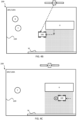
- Figure 4B shows an example where the robotic lawnmower 100 has reached the reference object (the house) and confirmed its position.
- the operating distance in some embodiments the budget distance
- the robotic lawnmower 100 continues operating seeking out the further reference object as for navigating to the (first) reference object discussed above.
- the robotic lawnmower 100 reaches the end of the satellite shadowed area and continues operation along the intended operating pattern (without the reference object).
- the robotic lawnmower 100 halts operating and possibly issues an error message in some embodiments.
- the robotic lawnmower 100 determines that the robotic lawnmower 100 still is allowed to navigate a remainder of the operating distance
- the robotic lawnmower 100 is configured to query the map application for a further reference object and attempt to navigate to the further reference object.
- Figure 4C shows an example where the robotic lawnmower 100 encounters or reaches an object (in this example a rock R) at an unexpected position.
- the robotic lawnmower 100 is configured to determine that the path to the reference object is unsuccessful and query the map application for a further reference object.
- Figure 4D shows the example where the robotic lawnmower 100 is attempting to reach the other known obstacle, the wall W, being a further reference object.
- the robotic lawnmower 100 is configured to determine a new path to the reference object and attempt the new path.
- Figure 4E shows the example where the robotic lawnmower 100 is attempting to reach the reference object through an alternative path.
- Figure 5 shows a flowchart for a general method according to herein.
- the method is for use in a robotic lawnmower as in figure 1 in a manner as discussed above in relation to figures 4A , 4B , 4C , 4D and 4E .
- the method comprises the robotic lawnmower 100 operating 510 in the operational area 205 possibly according to an intended pattern.
- the robotic lawnmower 100 determines 520 that the robotic lawnmower 100 is in a satellite shadowed area, the robotic lawnmower 100 queries 530 the map application for a reference object as discussed above.
- the robotic lawnmower then navigates 540 to the reference object for an (allowed) operating distance.
- the robotic lawnmower 100 determines 550 that the reference object has been reached and if so, confirms 560 the position of the robotic lawnmower 100.
- the deduced reckoning sensors are also calibrated based on the confirmed new position as part of the confirmation of the position.
- the allowed distance is renewed (as in increased) 565 as the position is confirmed. In some embodiments the allowed distance is increased by being set as discussed above. In some embodiments the allowed distance is increased by being increased by the distance travelled since the last confirmed position (i.e. the distance travelled to reach the reference object).
- the robotic lawnmower 100 queries 540 for a further reference object and continues as per above and as indicated by the arrow in figure 5 .
- the robotic lawnmower determines that the reference object has not been reached at the expected position (arrow referenced NO in figure 5 )
- the robotic lawnmower queries for a (further) reference object. In some embodiments this is continued until the allowed distance is consumed.
- the navigating and reconfirming of positions is continued while the robotic lawnmower 100 determines that the robotic lawnmower 100 is in the satellite shadowed area, and as the robotic lawnmower 100 again receives reliable satellite reception, the robotic lawnmower 100 continues operation 570.
Landscapes
- Engineering & Computer Science (AREA)
- Radar, Positioning & Navigation (AREA)
- Remote Sensing (AREA)
- Physics & Mathematics (AREA)
- General Physics & Mathematics (AREA)
- Aviation & Aerospace Engineering (AREA)
- Automation & Control Theory (AREA)
- Life Sciences & Earth Sciences (AREA)
- Environmental Sciences (AREA)
- Computer Networks & Wireless Communication (AREA)
- Control Of Position, Course, Altitude, Or Attitude Of Moving Bodies (AREA)
- Navigation (AREA)
Abstract
A method for use in a robotic lawnmower system (200) comprising a robotic lawnmower (100) arranged to operate in an operational area (205) based on the satellite navigation sensor (175),
determining (520) that the robotic lawnmower (100) is in a satellite shadowed area and in response thereto
querying (530) the map application (120A) for a reference object,
and navigate (540) to the reference object based on the deduced reckoning sensor (180),
determining (550) that the reference object has been reached based on the object sensor (185) and, if so,
confirming (560) a new position of the robotic lawnmower (100),
determining that the robotic lawnmower (100) is not in the satellite shadowed area and in response thereto
again operate (570) based on the satellite navigation sensor (175).
determining (520) that the robotic lawnmower (100) is in a satellite shadowed area and in response thereto
querying (530) the map application (120A) for a reference object,
and navigate (540) to the reference object based on the deduced reckoning sensor (180),
determining (550) that the reference object has been reached based on the object sensor (185) and, if so,
confirming (560) a new position of the robotic lawnmower (100),
determining that the robotic lawnmower (100) is not in the satellite shadowed area and in response thereto
again operate (570) based on the satellite navigation sensor (175).
Description
- This application relates to a robotic lawnmower and in particular to a system and a method for providing an improved navigation for robotic lawnmowers in such a system.
- Automated or robotic lawnmowers are becoming increasingly more popular and so is the use of the robotic lawnmower in various types of operational areas. Furthermore, there is also a trend for satellite navigation and virtual borders for such robotic lawnmowers and specifically for performing (sophisticated) patterns in the grass or other work that requires high accuracy. However, sometimes the robotic lawnmowers are not able to properly navigate the pattern, especially in areas where there are many structures or foliage.
- Thus, there is a need for an improved manner of navigating with high accuracy, especially in areas where there are many structures or foliage.
- The inventors are proposing to achieve this by maneuvering the robotic lawnmower to reference objects having known positions and there (re)confirm the robotic lawnmower's position and allow to it continue operating based on the confirmed position.
- It is therefore an object of the teachings of this application to overcome or at least reduce those problems by providing a robotic lawnmower system comprising a robotic lawnmower arranged to operate in an operational area, the robotic lawnmower comprising a satellite navigation sensor, a deduced reckoning sensor, an object sensor, a memory storing a memory application, and a controller configured for causing the robotic lawnmower to operate in the operational area based on the satellite navigation sensor, determining that the robotic lawnmower is in a satellite shadowed area and in response thereto querying the map application for a reference object, causing the robotic lawnmower to navigate to the reference object based on the deduced reckoning sensor, determining that the reference object has been reached based on the object sensor and, if so, confirming a new position of the robotic lawnmower, determining that the robotic lawnmower is not in the satellite shadowed area and in response thereto causing the robotic lawnmower to again operate in the operational area based on the satellite navigation sensor.
- This has the benefit that the robotic lawnmower is enabled to navigate also in satellite shadowed areas with a high accuracy, as the position is again and again confirmed.
- Further embodiments are as in the following detailed description and as per the appended patent claims.
- It is also an object of the teachings of this application to overcome the problems by providing a method for use in robotic lawnmower system comprising a robotic lawnmower arranged to operate in an operational area, the robotic lawnmower comprising a satellite navigation sensor, a deduced reckoning sensor, an object sensor, and a memory storing a memory application, wherein the method comprises causing the robotic lawnmower to operate in the operational area based on the satellite navigation sensor, determining that the robotic lawnmower is in a satellite shadowed area and in response thereto querying the map application for a reference object, causing the robotic lawnmower to navigate to the reference object based on the deduced reckoning sensor, determining that the reference object has been reached based on the object sensor and, if so, confirming a new position of the robotic lawnmower, determining that the robotic lawnmower is not in the satellite shadowed area and in response thereto causing the robotic lawnmower to again operate in the operational area based on the satellite navigation sensor.
- Further embodiments and aspects are as in the attached patent claims and as discussed in the detailed description.
- Other features and advantages of the disclosed embodiments will appear from the following detailed disclosure, from the attached dependent claims as well as from the drawings. Generally, all terms used in the claims are to be interpreted according to their ordinary meaning in the technical field, unless explicitly defined otherwise herein. All references to "a/an/the [element, device, component, means, step, etc.]" are to be interpreted openly as referring to at least one instance of the element, device, component, means, step, etc., unless explicitly stated otherwise. The steps of any method disclosed herein do not have to be performed in the exact order disclosed, unless explicitly stated.
- The invention will be described in further detail under reference to the accompanying drawings in which:
-
Figure 1 shows a schematic view of the components of an example of a robotic lawnmower according to some example embodiments of the teachings herein; -
Figure 2 shows a schematic view of a robotic lawnmower system according to some example embodiments of the teachings herein; -
Figure 3 shows a schematic view of an intended pattern being serviced in a traditional manner; -
Figures 4A ,4B and 4C show a schematic view of an intended pattern being serviced according to some example embodiments of the teachings herein; - Figures 5A, 5B and 5C show a schematic view of an intended pattern being serviced according to some example embodiments of the teachings herein; and
- Figure 6 shows a corresponding flowchart for a method according to some example embodiments of the teachings herein.
- The disclosed embodiments will now be described more fully hereinafter with reference to the accompanying drawings, in which certain embodiments of the invention are shown. This invention may, however, be embodied in many different forms and should not be construed as limited to the embodiments set forth herein. Like reference numbers refer to like elements throughout.
-
Figure 1 shows a schematic overview of arobotic lawnmower 100. Therobotic lawnmower 100 may be a multi-chassis type or a mono-chassis type (as infigure 1 ). A multi-chassis type comprises more than one main body parts that are movable with respect to one another. A mono-chassis type comprises only one main body part. - It should be noted that robotic lawnmower may be of different sizes, where the size ranges from merely a few decimetres for small garden robots, to even more than 1 meter for large robots arranged to service for example airfields.
- It should also be noted that the robotic lawnmower is a self-propelled robotic lawnmower, capable of autonomous navigation within a work area, where the robotic lawnmower propels itself across or around the work area in a pattern (random or predetermined).
- The
robotic lawnmower 100 has amain body part 140, possibly comprising achassis 140 and anouter shell 140A, and a plurality of wheels 130 (in this example four wheels 130, but other number of wheels are also possible, such as three or six). - The
main body part 140 substantially houses all components of therobotic lawnmower 100. At least some of the wheels 130 are drivably connected to at least oneelectric motor 155 powered by abattery 150. It should be noted that even if the description herein is focused on electric motors, combustion engines may alternatively be used, possibly in combination with an electric motor. In the example offigure 1 , each of the wheels 130 is connected to a common or to a respectiveelectric motor 155 for driving the wheels 130 to navigate therobotic lawnmower 100 in different manners. The wheels, themotor 155 and possibly thebattery 150 are thus examples of components making up a propulsion device. By controlling themotors 155, the propulsion device may be controlled to propel therobotic lawnmower 100 in a desired manner, and the propulsion device will therefore be seen as synonymous with the motor(s) 150. - It should be noted that wheels 130 driven by electric motors is only one example of a propulsion system and other variants are possible such as caterpillar tracks.
- The
robotic lawnmower 100 also comprises acontroller 110 and a computer readable storage medium ormemory 120. Thecontroller 110 may be implemented using instructions that enable hardware functionality, for example, by using executable computer program instructions in a general-purpose or special-purpose processor that may be stored on thememory 120 to be executed by such a processor. Thecontroller 110 is configured to read instructions from thememory 120 and execute these instructions to control the operation of therobotic lawnmower 100 including, but not being limited to, the propulsion and navigation of the robotic lawnmower. - The
controller 110 in combination with theelectric motor 155 and the wheels 130 forms the base of a navigation system (possibly comprising further components) for the robotic lawnmower, enabling it to be self-propelled as discussed. - The
controller 110 may be implemented using any suitable, available processor or Programmable Logic Circuit (PLC). Thememory 120 may be implemented using any commonly known technology for computer-readable memories such as ROM, FLASH, DDR, or some other memory technology. - The
robotic lawnmower 100 is further arranged with awireless communication interface 115 for communicating with other devices, such as a server, a personal computer, a smartphone, the charging station, and/or other robotic lawnmowers. Examples of such wireless communication devices are Bluetooth®, WiFi® (IEEE802.11b), Global System Mobile (GSM) and LTE (Long Term Evolution), to name a few. - The
robotic lawnmower 100 also comprises a grass cutting device 160, such as a rotating blade 160/2 driven by a cutter motor 160/1. - The
robotic lawnmower 100 further comprises at least one satellitesignal navigation sensor 175 configured to provide navigational information (such as position) based on receiving one or more signals from a satellite - possibly in combination with receiving a signal from a beacon. In some embodiments the satellite navigation sensor is a GPS (Global Positioning System) device or other Global Navigation Satellite System (GNSS) device. In some embodiments the satellite navigation sensor is a RTK sensor. - The
robotic lawnmower 100 may also or alternatively comprise deducedreckoning sensors 180. The deduced reckoning sensors may be odometers, accelerometer or other deduced reckoning sensors. In some embodiments, the deduced reckoning sensors are comprised in the propulsion device, wherein a deduced reckoning navigation may be provided by knowing the current supplied to a motor and the time the current is supplied, which will give an indication of the speed and thereby distance for the corresponding wheel. - The
robotic lawnmower 100 is in some embodiments arranged to operate according to a map application representing one or more work areas (and possibly the surroundings of the work area(s)) stored in thememory 120 of therobotic lawnmower 100. The map application may be generated or supplemented as therobotic lawnmower 100 operates or otherwise moves around in thework area 205. In some embodiments, the map application includes one or more start regions and one or more goal regions for each work area. In some embodiments, the map application also includes one or more transport areas. Therobotic lawnmower 100 is in some embodiments arranged to navigate according to the map based on thesatellite navigation sensor 175 and/or the deducedreckoning sensors 180. - For enabling the
robotic lawnmower 100 to navigate with reference to a boundary wire (referenced 220 infigure 2 ) emitting a magnetic field caused by a control signal transmitted through the wire, therobotic lawnmower 100 is in some embodiments configured to have at least onemagnetic field sensor 170 arranged to detect the magnetic field and for detecting the wire and/or for receiving (and possibly also sending) information to/from a signal generator. - The
robotic lawnmower 100 also comprises one or more than oneobject sensors 185. In some embodiments theobject sensor 185 is a collision sensor which is configured to detect a collision (possibly through a change in geometry of the housing of therobotic lawnmower 100 or by detecting a deceleration pattern specific to collisions through the use of a gyro or other inertial measurement unit (IMU))) with an object. Collision sensors are generally known and no further details will be given. In some alternative or additional embodiments theobject sensor 185 is a visual sensor, such as an image sensor which is configured to detect an object by capturing one or more images and performing image analysis on these images. Such image sensors are generally known and no further details will be given. In some alternative or additional embodiments theobject sensor 185 is a distance sensor, such as laser or radar, which is configured to detect an object by detecting that the distance to something in front of the robotic lawnmower is below a threshold distance. Such distance sensors are generally known and no further details will be given. -
Figure 2 shows arobotic lawnmower system 200 in some embodiments. The schematic view is not to scale. Therobotic lawnmower system 200 comprises one or morerobotic lawnmowers 100 according to the teachings herein. It should be noted that theoperational area 205 shown infigure 2 is simplified for illustrative purposes. The schematic view offigure 2 also illustrates a graphic representation of amap application 120A stored in the memory of therobotic lawnmower 100 as discussed in the above. - The
robotic lawnmower 100 is also or alternatively arranged to operate according to a virtual boundary referenced 220 specified in themap application 120A based on the satellite navigation sensor(s) 175, and/or the deducedreckoning sensors 180. - The example of
figure 2 also shows a satellite to represent the various satellites referenced S necessary for establishing or determining a position using satellite navigation. Also, the satellite offigure 2 is taken to also represent various types of beacons that may be utilized in order to increase the accuracy and/or coverage of a satellite navigation system, such as in Real Time Kinetic (RTK) systems. - The robotic lawnmower system comprises, in some embodiments, a boundary wire also referenced 220 through which a control signal is transmitted thereby generating a magnetic field, and which magnetic field is sensed by sensor(s) (170) in the
robotic lawnmower 100. In some embodiments the control signal is generated by a signal generator comprised in a station. The boundary may thus in some embodiments act as a supplement to the virtual boundary. - As with
figure 1 , the robotic lawnmower(s) is exemplified by a robotic lawnmower, whereby the robotic lawnmower system may be a robotic lawnmower system or a system comprising a combination of robotic lawnmowers, one being a robotic lawnmower, but the teachings herein may also be applied to other robotic lawnmowers adapted to operate within a work area. - In some embodiments the robotic lawnmower is arranged or configured to traverse and operate in work areas that are not essentially flat, but contain terrain that is of varying altitude, such as undulating, comprising hills or slopes or such. The ground of such terrain is not flat and it is not straightforward how to determine an angle between a sensor mounted on the robotic lawnmower and the ground. The robotic lawnmower is also or alternatively arranged or configured to traverse and operate in a work area that contains obstacles that are not easily discerned from the ground. Examples of such are grass or moss-covered rocks, roots or other obstacles that are close to ground and of a similar colour or texture as the ground. The robotic lawnmower is also or alternatively arranged or configured to traverse and operate in a work area that contains obstacles that are overhanging, i.e. obstacles that may not be detectable from the ground up, such as low hanging branches of trees or bushes. Such a garden is thus not simply a flat lawn to be mowed or similar, but a work area of unpredictable structure and characteristics. The
work area 205 exemplified with referenced tofigure 2 , may thus be such a non-uniform work area as disclosed in this paragraph that the robotic lawnmower is arranged to traverse and/or operate in. - As is shown in
figure 2 there may be obstacles such as houses (referenced H), structures, trees (referenced T), rocks (referenced R) to mention a few examples that block signal reception in certain areas, hereafter referred to as shadowed areas. Infigure 2 such obstacles are indicated and referenced H (as in house). Additionally the boundary may comprise one or more than one such obstacles, for example a wall referenced W or fence. - Returning to the map application, the map application is in some embodiments configured to store the location of one, some or all of these obstacles. The
map application 120 thus contain one or more than one stored or known obstacles and therobotic lawnmower 100 thus has knowledge of the position of one or more than one of the obstacles in the operational area, be it trees, stones, structures or walls. In some embodiments the boundary wire is also a known obstacle. -
Figure 3 is a schematic view of arobotic lawnmower system 200 as infigure 2 , therobotic lawnmower system 200 comprising one or more robotic lawnmower(s) 100 as discussed in relation tofigures 1 and 2 . - As is illustrated in
figure 3 , there may be areas where the satellite reception is insufficient to determine a position of therobotic lawnmower 100 accurately. As a skilled person would understand determining a position utilizing satellite navigation (including possibly beacon-based systems) requires the reception of several reference signals transmitted from the satellites and/or beacons. For example, to establish a position in three dimensions requires 4 signals. However, in order to accurately determine such a position requires many more signals, and most contemporary satellite navigation systems utilize many more satellites, for example 12 or 16 signals. As a skilled person would also understand there may be areas where one or more of the satellites (and/or beacons) are blocked by for example structures or foliage. In such areas, the received signals are not of a sufficiently high quality - as regards the number of signals received and/or the signal level that the signals are received at. Such an area will hereafter be defined as an area where the received satellite signals (including any beacon signals) are received at a signal quality level falling under a threshold acceptance level and be referred to as a satellite shadowed area. Therobotic lawnmower 100 is in some embodiments configured to determine that therobotic lawnmower 100 is in such an area by determining that the number of reference (satellite or beacon) signals received fall under an acceptance number and/or by determining that the quality of received reference (satellite or beacon) signals fall under an acceptance level. - Returning to
figure 3 , in such satellite shadowed areas, therobotic lawnmower 100 may be unable to determine its position adequately. In some prior art systems, therobotic lawnmower 100 is then configured to supplement the navigation based on for example deduced reckoning. However, deduced reckoning suffers from a number of drawbacks and can thus not be relied upon and the prior art systems therefore propose to leave the satellite shadowed area as soon as possible and then to reconfirm the position of therobotic lawnmower 100 and continue operation, possibly after calibrating the deduced reckoning sensors. However, the inventors have proposed an alternative to such systems which enables for a better servicing of the satellite shadowed areas that does not require therobotic lawnmower 100 to (hurriedly) leave the satellite shadowed area. - In
figure 3 there is such a satellite shadowed area exemplified behind the house H and indicated by the dotted area and referenced SSA, where it is illustrated how a signal from the satellite S is blocked by the house. Anyrobotic lawnmower 100 operating in the satellite shadowed area will thus suffer from a reduced accuracy when operating according to a prior art system. -
Figure 4A is a schematic view of arobotic lawnmower system 200 as infigure 2 , therobotic lawnmower system 200 comprising one or more robotic lawnmower(s) 100 as discussed in relation tofigures 1 and 2 , wherein therobotic lawnmower 100 is configured to operate as per the teachings herein. - As the
robotic lawnmower 100 determines that the accuracy for determining a location is reduced, such as by determining that robotic lawnmower is in a satellite shadowed area, therobotic lawnmower 100 notes its position. In some embodiments the position is the last accurately determined position. In some embodiments the position is the current position. In some embodiments therobotic lawnmower 100 also notes a budget distance. In some embodiments the budget distance is determined based on the length of therobotic lawnmower 100, for example 1 or 2 times the length of the robotic lawnmower. In some embodiments the budget distance is determined based on the accuracy of the satellite navigation, for example 1, 5 or 10 meters or any range there inbetween. - The
robotic lawnmower 100 then queries the map application for a known obstacle. In some embodiments therobotic lawnmower 100 queries themap application 120A for a known obstacle within the budget distance. In some embodiments therobotic lawnmower 100 queries themap application 120A for a known obstacle within for example 1 or 2 times the length of the robotic lawnmower. In some embodiments therobotic lawnmower 100 queries themap application 120A for a known obstacle within for example 1, 5 or 10 meters or any range there inbetween. In some embodiments therobotic lawnmower 100 queries themap application 120A for the known obstacle being closest to therobotic lawnmower 100. In some embodiments therobotic lawnmower 100 queries themap application 120A for the known obstacle being closest to therobotic lawnmower 100 in the direction of travel (+/- 90 degrees) for therobotic lawnmower 100. the known obstacle being closest to therobotic lawnmower 100 in the direction or path of an intended operating pattern. - The queried obstacle is then used or selected as a reference object for the
robotic lawnmower 100, and therobotic lawnmower 100 continues to operate for a distance or time. In some embodiments the operating distance is equal to or less than the budget distance. In some embodiments the operating distance is equal to or less than for example 1 or 2 times the length of the robotic lawnmower. In some embodiments the operating distance is equal to or less than for example 1, 5 or 10 meters or any range there inbetween. No matter what the operating distance is, the operating distance includes the distance required to travel to the reference object. Therobotic lawnmower 100 is thus enabled to continue operating (for a distance) even in the satellite shadowed area. Unless the satellite reception becomes reliable again (i.e. that therobotic lawnmower 100 determines that it is no longer operating in a satellite shadowed area), therobotic lawnmower 100 moves to the reference object. - In the example of
figure 4A the obstacle closest to therobotic lawnmower 100 is the house H, and is assumed to be the reference object selected. Therobotic lawnmower 100 offigure 4A is thus enabled to continue operating in its intended direction for a distance and is then controlled to navigate to the reference object as is indicated by the arrow infigure 4A . - During this continued navigation the
robotic lawnmower 100 is in some embodiments configured to operate according to the deducedreckoning sensors 180. - As the
robotic lawnmower 100 approaches or reaches the reference object therobotic lawnmower 100 determines that the reference object has been reached through the use of theobject sensor 185. How therobotic lawnmower 100 determines that the reference object has been reached depends on the type of obstacle sensor used. As an example, if theobstacle sensor 185 is a collision sensor, therobotic lawnmower 100 determines that the reference object has been reached by detecting a collision. As another example, if theobstacle sensor 185 is an image sensor, therobotic lawnmower 100 determines that the reference object has been reached by identifying the reference object through image processing. As another example, if theobstacle sensor 185 is a distance sensor, therobotic lawnmower 100 determines that the reference object has been reached by detecting that the distance to any object in front of therobotic lawnmower 100 has fallen under a detection distance, for example 10, 20 or 50 cm. - In some embodiments the
robotic lawnmower 100 is further configured to determine that the reference object was reached by determining that the reference object is at an expected position. In some such embodiments therobotic lawnmower 100 is configured to determine that the reference object is at the expected position by determining the current position of the robotic lawnmower 100 (based on the deduced reckoning sensors 180) and comparing to the stored position for the reference object as per themap application 120A. In some alternative or additional such embodiments, therobotic lawnmower 100 is configured to determine that the reference object is at the expected position by determining a travelled distance and comparing this to a determined expected distance to be travelled to reach the reference object, i.e. the distance from the previous position of therobotic lawnmower 100 to the reference object (along an intended path to the reference object). - As the robotic lawnmower determines that the reference object has been reached, the
robotic lawnmower 100 determines its (new) position and queries the map application for a further reference object based on its new position. The new position can be confirmed or determined more accurately as therobotic lawnmower 100 knows that the new position is adjacent the reference object.Figure 4B shows an example where therobotic lawnmower 100 has reached the reference object (the house) and confirmed its position. As the position has been confirmed the operating distance (in some embodiments the budget distance) is renewed and therobotic lawnmower 100 continues operating seeking out the further reference object as for navigating to the (first) reference object discussed above. - In the example of
figure 4B therobotic lawnmower 100 reaches the end of the satellite shadowed area and continues operation along the intended operating pattern (without the reference object). - If the reference object is determined to not be at the expected position, the
robotic lawnmower 100 halts operating and possibly issues an error message in some embodiments. In some alternative embodiments, where therobotic lawnmower 100 determines that therobotic lawnmower 100 still is allowed to navigate a remainder of the operating distance, therobotic lawnmower 100 is configured to query the map application for a further reference object and attempt to navigate to the further reference object.Figure 4C shows an example where therobotic lawnmower 100 encounters or reaches an object (in this example a rock R) at an unexpected position. In this example, and in some embodiments therobotic lawnmower 100 is configured to determine that the path to the reference object is unsuccessful and query the map application for a further reference object.Figure 4D shows the example where therobotic lawnmower 100 is attempting to reach the other known obstacle, the wall W, being a further reference object. - In some alternative embodiments the
robotic lawnmower 100 is configured to determine a new path to the reference object and attempt the new path.Figure 4E shows the example where therobotic lawnmower 100 is attempting to reach the reference object through an alternative path. -
Figure 5 shows a flowchart for a general method according to herein. The method is for use in a robotic lawnmower as infigure 1 in a manner as discussed above in relation tofigures 4A ,4B ,4C ,4D and 4E . The method comprises therobotic lawnmower 100 operating 510 in theoperational area 205 possibly according to an intended pattern. As therobotic lawnmower 100 determines 520 that therobotic lawnmower 100 is in a satellite shadowed area, therobotic lawnmower 100queries 530 the map application for a reference object as discussed above. The robotic lawnmower then navigates 540 to the reference object for an (allowed) operating distance. Therobotic lawnmower 100 then determines 550 that the reference object has been reached and if so, confirms 560 the position of therobotic lawnmower 100. In some embodiments the deduced reckoning sensors are also calibrated based on the confirmed new position as part of the confirmation of the position. - In some embodiments the allowed distance is renewed (as in increased) 565 as the position is confirmed. In some embodiments the allowed distance is increased by being set as discussed above. In some embodiments the allowed distance is increased by being increased by the distance travelled since the last confirmed position (i.e. the distance travelled to reach the reference object).
- As the reference object has been reached, the
robotic lawnmower 100queries 540 for a further reference object and continues as per above and as indicated by the arrow infigure 5 . - In some embodiments, and if the robotic lawnmower determines that the reference object has not been reached at the expected position (arrow referenced NO in
figure 5 ), the robotic lawnmower queries for a (further) reference object. In some embodiments this is continued until the allowed distance is consumed. - The navigating and reconfirming of positions is continued while the
robotic lawnmower 100 determines that therobotic lawnmower 100 is in the satellite shadowed area, and as therobotic lawnmower 100 again receives reliable satellite reception, therobotic lawnmower 100 continuesoperation 570.
Claims (16)
- A robotic lawnmower system (200) comprising a robotic lawnmower (100) arranged to operate in an operational area (205), the robotic lawnmower (100) comprising a satellite navigation sensor (175), a deduced reckoning sensor (180), an object sensor (185), a memory storing a memory application (120A), and a controller (110), wherein the controller (110) is configured tocause the robotic lawnmower (100) to operate (510) in the operational area (205) based on the satellite navigation sensor (175),determine (520) that the robotic lawnmower (100) is in a satellite shadowed area and in response theretoquery (530) the map application (120A) for a reference object,cause the robotic lawnmower (100) to navigate (540) to the reference object based on the deduced reckoning sensor (180),determine (550) that the reference object has been reached based on the object sensor (185) and, if so,confirm (560) a new position of the robotic lawnmower (100),determine that the robotic lawnmower (100) is not in the satellite shadowed area and in response theretocause the robotic lawnmower (100) to again operate (570) in the operational area (205) based on the satellite navigation sensor (175).
- The robotic lawnmower system (200) according to claim 1, wherein the controller (110) is further configured to
query (540) the map application (120A) for a further reference object based on the new position and cause the robotic lawnmower (100) to navigate (540) to the further reference object based on the deduced reckoning sensor (180). - The robotic lawnmower system (200) according to claim 1 or 2, wherein the controller (110) is further configured to cause the robotic lawnmower (100) to navigate (540) to the further reference object based on the deduced reckoning sensor (180) for an allowed distance.
- The robotic lawnmower system (200) according to claim 1 or 2, wherein the controller (110) is further configured to increase (565) the allowed distance as the new position is confirmed.
- The robotic lawnmower system (200) according to any preceding claim, wherein the controller (110) is further configured to cause the robotic lawnmower (100) to navigate in the operational area (205) according to an intended pattern.
- The robotic lawnmower system (200) according to any preceding claim, wherein the controller (110) is further configured to
determines that the reference object has been reached by determining that the reference object is at an expected position. - The robotic lawnmower system (200) according to claim 6, wherein the controller (110) is further configured to determine that the reference object has not been reached by determining that the reference object is not at an expected position and in response thereto query the map application for a further reference object.
- The robotic lawnmower system (200) according to claim 6, wherein the controller (110) is further configured to determine that the reference object has not been reached by determining that the reference object is not at an expected position and in response thereto cause the robotic lawnmower (100) to navigate to the reference object along an alternative path.
- The robotic lawnmower system (200) according to any preceding claim, wherein the controller (110) is further configured to query the map application (120A) for the reference obstacle within the allowed distance.
- The robotic lawnmower system (200) according to claim 9, wherein the allowed distance is 1 or 2 times the length of the robotic lawnmower.
- The robotic lawnmower system (200) according to claim 9, wherein the allowed distance is 1, 5 or 10 meters or any range there inbetween.
- The robotic lawnmower system (200) according to claim 9, 10 or 11, wherein the controller (110) is further configured to query the map application 120A for the reference object being a known obstacle being closest to the robotic lawnmower (100).
- The robotic lawnmower system (200) according to claim 12, wherein the controller (110) is further configured to query the map application (120A) for the known obstacle being closest to the robotic lawnmower (100) in a direction of travel for the robotic lawnmower (100), +/- 90 degrees.
- The robotic lawnmower system (200) according to claim 13, wherein the controller (110) is further configured to query the map application (120A) for the known obstacle being closest to the robotic lawnmower (100) in a path of an intended operating pattern.
- The robotic lawnmower system (200) according to any preceding claim, wherein the controller (110) is further configured to calibrate the deduced reckoning sensor (180) based on the confirmed new position.
- A method for use in a robotic lawnmower system (200) comprising a robotic lawnmower (100) arranged to operate in an operational area (205), the robotic lawnmower (100) comprising a satellite navigation sensor (175), a deduced reckoning sensor (180), an object sensor (185), and a memory storing a memory application (120A), wherein the method comprisescausing the robotic lawnmower (100) to operate (510) in the operational area (205) based on the satellite navigation sensor (175),determining (520) that the robotic lawnmower (100) is in a satellite shadowed area and in response theretoquerying (530) the map application (120A) for a reference object,causing the robotic lawnmower (100) to navigate (540) to the reference object based on the deduced reckoning sensor (180),determining (550) that the reference object has been reached based on the object sensor (185) and, if so,confirming (560) a new position of the robotic lawnmower (100),determining that the robotic lawnmower (100) is not in the satellite shadowed area and in response theretocausing the robotic lawnmower (100) to again operate (570) in the operational area (205) based on the satellite navigation sensor (175).
Applications Claiming Priority (1)
| Application Number | Priority Date | Filing Date | Title |
|---|---|---|---|
| SE2350697A SE546890C2 (en) | 2023-06-08 | 2023-06-08 | Improved navigation for a robotic work tool system |
Publications (1)
| Publication Number | Publication Date |
|---|---|
| EP4474937A1 true EP4474937A1 (en) | 2024-12-11 |
Family
ID=91067109
Family Applications (1)
| Application Number | Title | Priority Date | Filing Date |
|---|---|---|---|
| EP24174913.4A Pending EP4474937A1 (en) | 2023-06-08 | 2024-05-08 | Improved navigation for a robotic lawnmower system |
Country Status (3)
| Country | Link |
|---|---|
| US (1) | US20240407290A1 (en) |
| EP (1) | EP4474937A1 (en) |
| SE (1) | SE546890C2 (en) |
Citations (4)
| Publication number | Priority date | Publication date | Assignee | Title |
|---|---|---|---|---|
| WO2017177929A1 (en) * | 2016-04-12 | 2017-10-19 | 苏州宝时得电动工具有限公司 | Automatic movement device for automatic working system, and control method therefor |
| US20210165109A1 (en) * | 2017-05-26 | 2021-06-03 | Positec Power Tools (Suzhou) Co., Ltd | Positioning apparatus and method and self-moving device |
| US20220124973A1 (en) * | 2019-01-08 | 2022-04-28 | Husqvarna Ab | A Robotic Tool, and Methods of Navigating and Defining a Work Area for the Same |
| US20230115421A1 (en) * | 2019-12-13 | 2023-04-13 | Postiec Power Tools (Suzhou) Co.,Ltd. | Self-moving device and working method therefor |
Family Cites Families (12)
| Publication number | Priority date | Publication date | Assignee | Title |
|---|---|---|---|---|
| US7427950B2 (en) * | 2004-01-13 | 2008-09-23 | Navcom Technology, Inc. | Method for increasing the reliability of position information when transitioning from a regional, wide-area, or global carrier-phase differential navigation (WADGPS) to a local real-time kinematic (RTK) navigation system |
| JP4764070B2 (en) * | 2005-05-24 | 2011-08-31 | 本田技研工業株式会社 | Work station safety system |
| WO2015072896A1 (en) * | 2013-11-12 | 2015-05-21 | Husqvarna Ab | Improved navigation for a robotic working tool |
| WO2015094054A1 (en) * | 2013-12-19 | 2015-06-25 | Husqvarna Ab | Navigation for a robotic working tool |
| SE1451645A1 (en) * | 2014-12-23 | 2016-05-31 | Husqvarna Ab | Improved navigation for a robotic lawnmower |
| SE540131C2 (en) * | 2014-12-24 | 2018-04-10 | Husqvarna Ab | Robotic work tool with trajectory correction |
| EP3384318B1 (en) * | 2015-12-02 | 2022-05-18 | Husqvarna AB | Improved navigation for a vehicle by implementing two operating modes |
| US10698413B2 (en) * | 2017-12-28 | 2020-06-30 | Savioke Inc. | Apparatus, system, and method for mobile robot relocalization |
| EP3761064B1 (en) * | 2018-02-28 | 2022-04-27 | Honda Motor Co., Ltd. | Position estimation device, moving body, position estimation method and program |
| SE547250C2 (en) * | 2021-10-19 | 2025-06-17 | Husqvarna Ab | Robotic work tool arranged to navigate in a shadowed area and a method therefor |
| EP4455821B1 (en) * | 2022-01-28 | 2026-03-25 | Yamabiko Corporation | Working robot system |
| EP4564115A1 (en) * | 2022-07-27 | 2025-06-04 | Greenworks (Jiangsu) Co., Ltd. | Gardening tool, control method therefor, and system |
-
2023
- 2023-06-08 SE SE2350697A patent/SE546890C2/en unknown
-
2024
- 2024-05-08 EP EP24174913.4A patent/EP4474937A1/en active Pending
- 2024-06-04 US US18/733,066 patent/US20240407290A1/en active Pending
Patent Citations (4)
| Publication number | Priority date | Publication date | Assignee | Title |
|---|---|---|---|---|
| WO2017177929A1 (en) * | 2016-04-12 | 2017-10-19 | 苏州宝时得电动工具有限公司 | Automatic movement device for automatic working system, and control method therefor |
| US20210165109A1 (en) * | 2017-05-26 | 2021-06-03 | Positec Power Tools (Suzhou) Co., Ltd | Positioning apparatus and method and self-moving device |
| US20220124973A1 (en) * | 2019-01-08 | 2022-04-28 | Husqvarna Ab | A Robotic Tool, and Methods of Navigating and Defining a Work Area for the Same |
| US20230115421A1 (en) * | 2019-12-13 | 2023-04-13 | Postiec Power Tools (Suzhou) Co.,Ltd. | Self-moving device and working method therefor |
Also Published As
| Publication number | Publication date |
|---|---|
| US20240407290A1 (en) | 2024-12-12 |
| SE2350697A1 (en) | 2024-12-09 |
| SE546890C2 (en) | 2025-03-04 |
Similar Documents
| Publication | Publication Date | Title |
|---|---|---|
| EP4118509B1 (en) | System and method for improved navigation of a robotic work tool | |
| EP4068040A1 (en) | Improved operation for a robotic work tool | |
| EP4419976B1 (en) | Improved navigation for a robotic lawnmower | |
| EP4314974A1 (en) | Improved navigation for a robotic work tool | |
| US20240407290A1 (en) | Navigation for a robotic lawnmower system | |
| EP4474938B1 (en) | Improved navigation for a robotic lawnmower system | |
| EP4085745B1 (en) | Improved navigation for a robotic work tool | |
| EP4546074A1 (en) | Improved navigation for a robotic work tool system | |
| EP4268565A1 (en) | Improved navigation for a robotic work tool system | |
| EP4421532A1 (en) | Improved satellite selection for a robotic work tool system | |
| EP4473821A1 (en) | Improved navigation for a robotic lawnmower system | |
| EP4586042A1 (en) | Improved determination of position for a robotic work tool | |
| EP4589399A1 (en) | Improved planning for a robotic work tool | |
| EP4659559A1 (en) | Improved navigation for a robotic lawnmower with regards to woody plants | |
| EP4381926A1 (en) | Improved operation for a robotic work tool | |
| US12487604B2 (en) | Navigation for a robotic work tool system | |
| EP4591695A1 (en) | Improved determination of position for a robotic work tool | |
| EP4483249B1 (en) | Improved mapping for a robotic work tool system | |
| EP4381925A1 (en) | Improved detection of a solar panel for a robotic work tool | |
| WO2023244150A1 (en) | Improved navigation for a robotic work tool system | |
| WO2023121528A1 (en) | Improved navigation for a robotic work tool system | |
| SE2250557A1 (en) | Navigation for a robotic work tool system | |
| SE545376C2 (en) | Navigation for a robotic work tool system |
Legal Events
| Date | Code | Title | Description |
|---|---|---|---|
| PUAI | Public reference made under article 153(3) epc to a published international application that has entered the european phase |
Free format text: ORIGINAL CODE: 0009012 |
|
| STAA | Information on the status of an ep patent application or granted ep patent |
Free format text: STATUS: REQUEST FOR EXAMINATION WAS MADE |
|
| 17P | Request for examination filed |
Effective date: 20240508 |
|
| AK | Designated contracting states |
Kind code of ref document: A1 Designated state(s): AL AT BE BG CH CY CZ DE DK EE ES FI FR GB GR HR HU IE IS IT LI LT LU LV MC ME MK MT NL NO PL PT RO RS SE SI SK SM TR |
|
| STAA | Information on the status of an ep patent application or granted ep patent |
Free format text: STATUS: EXAMINATION IS IN PROGRESS |
|
| 17Q | First examination report despatched |
Effective date: 20250704 |