EP4474918A1 - Method for recycling developing cartridge - Google Patents
Method for recycling developing cartridge Download PDFInfo
- Publication number
- EP4474918A1 EP4474918A1 EP23749684.9A EP23749684A EP4474918A1 EP 4474918 A1 EP4474918 A1 EP 4474918A1 EP 23749684 A EP23749684 A EP 23749684A EP 4474918 A1 EP4474918 A1 EP 4474918A1
- Authority
- EP
- European Patent Office
- Prior art keywords
- holder
- holder assembly
- gear cover
- storage medium
- gear
- Prior art date
- Legal status (The legal status is an assumption and is not a legal conclusion. Google has not performed a legal analysis and makes no representation as to the accuracy of the status listed.)
- Pending
Links
Images






Classifications
-
- G—PHYSICS
- G03—PHOTOGRAPHY; CINEMATOGRAPHY; ANALOGOUS TECHNIQUES USING WAVES OTHER THAN OPTICAL WAVES; ELECTROGRAPHY; HOLOGRAPHY
- G03G—ELECTROGRAPHY; ELECTROPHOTOGRAPHY; MAGNETOGRAPHY
- G03G15/00—Apparatus for electrographic processes using a charge pattern
- G03G15/06—Apparatus for electrographic processes using a charge pattern for developing
- G03G15/08—Apparatus for electrographic processes using a charge pattern for developing using a solid developer, e.g. powder developer
- G03G15/0894—Reconditioning of the developer unit, i.e. reusing or recycling parts of the unit, e.g. resealing of the unit before refilling with toner
-
- G—PHYSICS
- G03—PHOTOGRAPHY; CINEMATOGRAPHY; ANALOGOUS TECHNIQUES USING WAVES OTHER THAN OPTICAL WAVES; ELECTROGRAPHY; HOLOGRAPHY
- G03G—ELECTROGRAPHY; ELECTROPHOTOGRAPHY; MAGNETOGRAPHY
- G03G15/00—Apparatus for electrographic processes using a charge pattern
- G03G15/06—Apparatus for electrographic processes using a charge pattern for developing
- G03G15/08—Apparatus for electrographic processes using a charge pattern for developing using a solid developer, e.g. powder developer
- G03G15/0822—Arrangements for preparing, mixing, supplying or dispensing developer
- G03G15/0863—Arrangements for preparing, mixing, supplying or dispensing developer provided with identifying means or means for storing process- or use parameters, e.g. an electronic memory
-
- G—PHYSICS
- G03—PHOTOGRAPHY; CINEMATOGRAPHY; ANALOGOUS TECHNIQUES USING WAVES OTHER THAN OPTICAL WAVES; ELECTROGRAPHY; HOLOGRAPHY
- G03G—ELECTROGRAPHY; ELECTROPHOTOGRAPHY; MAGNETOGRAPHY
- G03G15/00—Apparatus for electrographic processes using a charge pattern
- G03G15/06—Apparatus for electrographic processes using a charge pattern for developing
- G03G15/08—Apparatus for electrographic processes using a charge pattern for developing using a solid developer, e.g. powder developer
- G03G15/0822—Arrangements for preparing, mixing, supplying or dispensing developer
- G03G15/0865—Arrangements for supplying new developer
- G03G15/0875—Arrangements for supplying new developer cartridges having a box like shape
-
- G—PHYSICS
- G03—PHOTOGRAPHY; CINEMATOGRAPHY; ANALOGOUS TECHNIQUES USING WAVES OTHER THAN OPTICAL WAVES; ELECTROGRAPHY; HOLOGRAPHY
- G03G—ELECTROGRAPHY; ELECTROPHOTOGRAPHY; MAGNETOGRAPHY
- G03G21/00—Arrangements not provided for by groups G03G13/00 - G03G19/00, e.g. cleaning, elimination of residual charge
- G03G21/16—Mechanical means for facilitating the maintenance of the apparatus, e.g. modular arrangements
-
- G—PHYSICS
- G03—PHOTOGRAPHY; CINEMATOGRAPHY; ANALOGOUS TECHNIQUES USING WAVES OTHER THAN OPTICAL WAVES; ELECTROGRAPHY; HOLOGRAPHY
- G03G—ELECTROGRAPHY; ELECTROPHOTOGRAPHY; MAGNETOGRAPHY
- G03G21/00—Arrangements not provided for by groups G03G13/00 - G03G19/00, e.g. cleaning, elimination of residual charge
- G03G21/16—Mechanical means for facilitating the maintenance of the apparatus, e.g. modular arrangements
- G03G21/18—Mechanical means for facilitating the maintenance of the apparatus, e.g. modular arrangements using a processing cartridge, whereby the process cartridge comprises at least two image processing means in a single unit
- G03G21/1803—Arrangements or disposition of the complete process cartridge or parts thereof
- G03G21/181—Manufacturing or assembling, recycling, reuse, transportation, packaging or storage
-
- G—PHYSICS
- G03—PHOTOGRAPHY; CINEMATOGRAPHY; ANALOGOUS TECHNIQUES USING WAVES OTHER THAN OPTICAL WAVES; ELECTROGRAPHY; HOLOGRAPHY
- G03G—ELECTROGRAPHY; ELECTROPHOTOGRAPHY; MAGNETOGRAPHY
- G03G21/00—Arrangements not provided for by groups G03G13/00 - G03G19/00, e.g. cleaning, elimination of residual charge
- G03G21/16—Mechanical means for facilitating the maintenance of the apparatus, e.g. modular arrangements
- G03G21/18—Mechanical means for facilitating the maintenance of the apparatus, e.g. modular arrangements using a processing cartridge, whereby the process cartridge comprises at least two image processing means in a single unit
- G03G21/1875—Mechanical means for facilitating the maintenance of the apparatus, e.g. modular arrangements using a processing cartridge, whereby the process cartridge comprises at least two image processing means in a single unit provided with identifying means or means for storing process- or use parameters, e.g. lifetime of the cartridge
- G03G21/1878—Electronically readable memory
-
- G—PHYSICS
- G03—PHOTOGRAPHY; CINEMATOGRAPHY; ANALOGOUS TECHNIQUES USING WAVES OTHER THAN OPTICAL WAVES; ELECTROGRAPHY; HOLOGRAPHY
- G03G—ELECTROGRAPHY; ELECTROPHOTOGRAPHY; MAGNETOGRAPHY
- G03G21/00—Arrangements not provided for by groups G03G13/00 - G03G19/00, e.g. cleaning, elimination of residual charge
- G03G21/16—Mechanical means for facilitating the maintenance of the apparatus, e.g. modular arrangements
- G03G21/18—Mechanical means for facilitating the maintenance of the apparatus, e.g. modular arrangements using a processing cartridge, whereby the process cartridge comprises at least two image processing means in a single unit
- G03G21/1875—Mechanical means for facilitating the maintenance of the apparatus, e.g. modular arrangements using a processing cartridge, whereby the process cartridge comprises at least two image processing means in a single unit provided with identifying means or means for storing process- or use parameters, e.g. lifetime of the cartridge
- G03G21/1878—Electronically readable memory
- G03G21/1882—Electronically readable memory details of the communication with memory, e.g. wireless communication, protocols
- G03G21/1885—Electronically readable memory details of the communication with memory, e.g. wireless communication, protocols position of the memory; memory housings; electrodes
-
- G—PHYSICS
- G03—PHOTOGRAPHY; CINEMATOGRAPHY; ANALOGOUS TECHNIQUES USING WAVES OTHER THAN OPTICAL WAVES; ELECTROGRAPHY; HOLOGRAPHY
- G03G—ELECTROGRAPHY; ELECTROPHOTOGRAPHY; MAGNETOGRAPHY
- G03G2215/00—Apparatus for electrophotographic processes
- G03G2215/00987—Remanufacturing, i.e. reusing or recycling parts of the image forming apparatus
-
- G—PHYSICS
- G03—PHOTOGRAPHY; CINEMATOGRAPHY; ANALOGOUS TECHNIQUES USING WAVES OTHER THAN OPTICAL WAVES; ELECTROGRAPHY; HOLOGRAPHY
- G03G—ELECTROGRAPHY; ELECTROPHOTOGRAPHY; MAGNETOGRAPHY
- G03G2221/00—Processes not provided for by group G03G2215/00, e.g. cleaning or residual charge elimination
- G03G2221/16—Mechanical means for facilitating the maintenance of the apparatus, e.g. modular arrangements and complete machine concepts
- G03G2221/18—Cartridge systems
- G03G2221/1823—Cartridges having electronically readable memory
Definitions
- the present disclosure relates to a method of recycling developing cartridges.
- Patent Document 1 describes a developing cartridge (1) that can be mounted on a drum cartridge (2).
- the developing cartridge (1) has an IC chip (18), which is a storage medium; an IC chip holder that holds the IC chip; and a holder cover that holds the IC chip holder.
- the IC chip (18) stores various information about the developing cartridge (1) (for example, information on the service life of components such as a developing roller (13)).
- the holder cover is fixed to a gear cover (152). Further, the gear cover (152) is fixed to an end of a casing (11) that can store toner.
- the developing cartridge is disassembled and necessary maintenance is performed, such as replacing or cleaning parts in the developing cartridge.
- the IC chip, IC chip holder, and holder cover in the developing cartridge may be replaced when recycling the cartridge.
- An object of the present disclosure is to provide a technique for facilitating mounting of a holder cover holding an IC chip holder on a gear cover in recycling of a developing cartridge.
- a first aspect provides a method of recycling a developing cartridge including: a housing configured to store developer therein; a gear cover positioned at one end of the housing in a first direction; a holder assembly; and a first screw for mounting the holder assembly on the gear cover, wherein the holder assembly includes: a storage medium; a storage medium holder holding the storage medium, the storage medium holder being movable relative to the housing and the gear cover; and a holder cover holding the storage medium holder.
- the method includes: a gear cover removing step of removing the gear cover having the holder assembly mounted thereon with the first screw from the housing; a screw removing step of removing, after the gear cover removing step, the first screw from the gear cover; a holder assembly removing step of removing, after the screw removing step, the holder assembly from the gear cover; a first gear cover mounting step of mounting, after the holder assembly removing step, the gear cover on a jig on which another holder assembly different from the removed holder assembly is mounted; a holder assembly mounting step of mounting, after the first gear cover mounting step, the another holder assembly on the gear cover with the first screw; and a second gear cover mounting step of mounting, after the holder assembly mounting step, the gear cover having the another holder assembly mounted thereon with the first screw on the housing.
- a storage medium holder of the another holder assembly is restricted from moving relative to the jig and a holder cover of the another holder assembly in a state where the another holder
- a second aspect is the method of recycling the developing cartridge according to the first aspect, in which, in the first gear cover mounting step, the storage medium holder of the another holder assembly is immovable relative to the jig and the holder cover of the another holder assembly in the state where the another holder assembly is mounted on the jig.
- a third aspect is the method of recycling the developing cartridge according to the first aspect or the second aspect, in which, the another holder assembly includes: another storage medium different from the storage medium of the holder assembly; another storage medium holder holding the storage medium, the another storage medium holder being different from the storage medium holder of the holder assembly; and another holder cover holding the another storage medium holder, the another holder cover being different from the holder cover of the holder assembly.
- the another storage medium holder is immovably mounted on the jig.
- a fourth aspect is the method of recycling the developing cartridge according to any one of the first to third aspects, in which: the jig has a first recess that is recessed in the first direction; and, in the first gear cover mounting step, the another holder assembly is mounted in the first recess.
- a fifth aspect is the method of recycling the developing cartridge according to any one of the first to fourth aspects, in which: the jig has a plurality of protrusions extending in the first direction; and, in the first gear cover mounting step, an outer peripheral surface of the gear cover contacts the plurality of protrusions.
- a sixth aspect is the method of recycling the developing cartridge according to any one of the first to fifth aspects, in which: the gear cover has a first screw hole in which the first screw can be inserted; the holder cover has a second screw hole in which the first screw can be inserted; and, in the holder assembly mounting step, the first screw is inserted into the first screw hole and the second screw hole from an inner surface of the gear cover in the first direction toward an outer surface of the gear cover in the first direction.
- a seventh aspect is the method of recycling the developing cartridge according to any one of the first to sixth aspects, in which: the storage medium holder includes a first holder holding the storage medium, a second holder positioned apart from the first holder in a second direction crossing the first direction, and a resilient member positioned between the first holder and the second holder and configured to expand and contract in the second direction; the jig has a first inner surface and a second inner surface positioned apart from the first inner surface in the second direction; the first inner surface contacts one end portion of the first holder in the second direction; and the second inner surface contacts another end portion of the first holder in the second direction.
- An eighth aspect is the method of recycling the developing cartridge according to any one of the first to seventh aspects, in which: the storage medium has an electrical contact surface; and, in the first gear cover mounting step, the electrical contact surface is positioned apart from the first inner surface.
- a ninth aspect is the method of recycling the developing cartridge according to any one of the first to eighth aspects, in which: in a case where the holder assembly is mounted on the jig by the gear cover removing step, another end portion of the second holder is positioned apart from the jig in the second direction.
- a tenth aspect is a method of recycling a developing cartridge including: a housing configured to store developer therein; a gear cover positioned at one end of the housing in a first direction; a holder assembly; and a first screw for mounting the holder assembly on the gear cover, wherein the holder assembly includes: a storage medium having an electrical contact surface; a storage medium holder holding the storage medium, the storage medium holder being movable relative to the housing and the gear cover; and a holder cover holding the storage medium holder.
- the method includes: a first gear cover removing step of removing the gear cover having the holder assembly mounted thereon with the first screw from the housing; a first holder assembly mounting step of mounting, after the first gear cover removing step, the holder assembly mounted on the gear cover with the first screw on a jig; a screw removing step of removing, after the first holder assembly mounting step, the first screw from the gear cover; and a second gear cover removing step of removing, after the screw removing step, the gear cover from the holder assembly while leaving the holder assembly on the jig.
- the storage medium holder of the holder assembly is restricted from moving relative to the jig and the holder cover of the holder assembly in a state where the holder assembly is mounted on the jig.
- An eleventh aspect is the method of recycling the developing cartridge according to any one of the tenth aspect, in which: the jig has a plurality of protrusions extending in the first direction; and in the first holder assembly mounting step, an outer peripheral surface of the gear cover contacts the plurality of protrusions.
- a twelfth aspect is the method of recycling the developing cartridge according to the tenth aspect or the eleventh aspect, which further includes: a first holder assembly removing step of removing, after the screw removing step, the holder assembly from the jig; a second holder assembly mounting step of mounting, after the first holder assembly removing step, another holder assembly different from the removed holder assembly on the jig; a gear cover mounting step of mounting, after the second holder assembly mounting step, the gear cover on the jig; and a third holder assembly mounting step of mounting, after the gear cover mounting step, the another holder assembly on the gear cover with the first screw.
- a thirteenth aspect is the method of recycling the developing cartridge according to the tenth aspect or the eleventh aspect, which further includes: a first holder assembly removing step of removing, after the screw removing step, the holder assembly from the jig; a storage medium removing step of removing, after the first holder assembly removing step, the storage medium from the storage medium holder; a storage medium mounting step of mounting, after the storage medium removing step, another storage medium different from the removed storage medium on the storage medium holder; a second holder assembly mounting step of mounting, after the storage medium mounting step, the storage medium holder having the another storage medium mounted thereon and the holder cover on the jig; a gear cover mounting step of mounting, after the second holder assembly mounting step, the gear cover on the jig; and a holder cover mounting step of mounting, after the gear cover mounting step, the holder cover on the gear cover with the first screw.
- a fourteenth aspect is the method of recycling the developing cartridge according to any one of the first to thirteenth aspects, in which: the developing cartridge further includes a developing roller rotatable about a developing roller axis extending in the first direction.
- the method further includes: a developing roller removing step of removing, after the first gear cover removing step, the developing roller from the housing; and a developing roller mounting step of mounting, after the developing roller removing step, another developing roller different from the removed developing roller on the housing.
- a fifteenth aspect is the method of recycling the developing cartridge according to any one of the first to fourteenth aspects, in which: the developing cartridge further includes: an agitator rotatable about an agitator axis extending in the first direction; and an agitator gear rotatable about the agitator axis together with the agitator.
- the method further includes: an agitator gear removing step of removing, after the first gear cover removing step, the agitator gear from the housing; and an agitator gear mounting step of mounting, after the agitator gear removing step, another agitator gear different from the removed agitator gear on the housing.
- the storage medium holder is immovable relative to the jig and the holder cover in a state where the another holder assembly is mounted on the jig. Therefore, the holder cover holding the storage medium holder can be easily mounted on the gear cover.
- the storage medium can be protected by the holder assembly that is positioned in the first recess of the jig.
- the holder assembly can be easily mounted on the gear cover since the gear cover is fixed in position by the plurality of protrusions.
- a decrease in clamping force of a first screw due to deformation of the second screw hole of the holder cover can be addressed by replacing the holder cover. Therefore, since the number of times the storage medium holder is replaced can be reduced, the cost of recycling the developing cartridge can be reduced.
- the first holder can be made immovable in the second direction upon mounting of the holder assembly on the jig.
- the electrical contact surface of the storage medium can be suppressed from contacting the first inner surface of the jig.
- the holder assembly can be easily mounted on the jig.
- the holder assembly can be easily removed from the gear cover since the gear cover can be fixed in position by the plurality of protrusions.
- the storage medium can be replaced with another storage medium.
- the developing roller can be replaced with a new developing roller.
- the agitator gear can be replaced with a new agitator gear.
- Fig. 1 is a perspective view of a developing cartridge 10 according to the embodiment.
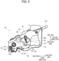
- Fig. 2 is a side view of the developing cartridge 10 illustrated in Fig. 1 .
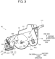
- Fig. 3 is a central cross-sectional view of the developing cartridge 10 illustrated in Fig. 1 .
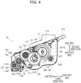
- Fig. 4 is a side view illustrating the developing cartridge 10 in a state where a gear cover 18 is removed.
- Fig. 5 is a bottom view illustrating one end of the developing cartridge 10 in a first direction.
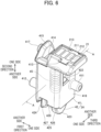
- Fig. 6 is a perspective view of an IC chip holder 24 according to the embodiment.
- Fig. 7 is a cross-sectional view of the IC chip holder 24 taken along a line A-A shown in Fig. 6 .
- first direction A direction in which a developing roller axis A12 of a developing roller 12 in the developing cartridge 10 extends
- second direction A direction crossing a first electrical contact surface 213 provided in the developing cartridge 10
- third direction A direction in which the developing roller 12 and a first agitator 14 ( Fig. 3 ) are aligned
- the first, second, and third directions all cross each other and, are preferably all orthogonal to each other.
- the developing cartridge 10 includes a housing 11, the developing roller 12, a supply roller 13, the first agitator 14, and a second agitator 15.
- the housing 11 can accommodate developer therein.
- the developer is toner, for example.
- the housing 11 extends in the first direction.
- the housing 11 has an opening 110 (see Fig. 4 ).
- the opening 110 is positioned at one end of the housing 11 in the third direction.
- the housing 11 has a first handle 113.
- the first handle 113 is positioned at another end of the housing 11 in the third direction.
- the housing 11 has a first outer surface 115, and a second outer surface 116.
- the first outer surface 115 is positioned at one end of the housing 11 in the second direction.
- the second outer surface 116 is positioned at another end of the housing 11 in the second direction.
- the developing roller 12 is rotatable about the developing roller axis A12 in a state where the developing cartridge 10 is attached to a body of a printer.
- the developing roller axis A12 extends in the first direction.
- the developing roller 12 is positioned in the opening 110. In other words, the developing roller 12 is positioned at the one end of the housing 11 in the third direction. In a state where the developing cartridge 10 is attached to the printer body, the developing roller 12 supplies the developer in the housing 11 onto a surface of a photosensitive drum (not illustrated).
- the developing roller 12 includes a developing roller body 121, and a developing roller shaft 122.
- the developing roller body 121 has a cylindrical shape that extends in the first direction.
- the developing roller body 121 is configured of an electrically-conductive rubber, for example.
- the developing roller shaft 122 has a columnar shape that extends along the developing roller axis A12.
- the developing roller shaft 122 is made of metal, for example.
- the developing roller shaft 122 is positioned radially inside the developing roller body 121.
- the developing roller shaft 122 penetrates through the developing roller body 121 in the first direction.
- the developing roller shaft 122 need not penetrate the developing roller body 121, but may be mounted in both ends of the developing roller body 121.
- the developing roller 12 is rotatable about the developing roller shaft 122.
- the supply roller 13 supplies the developer within the housing 11 onto a surface of the developing roller 12.
- the supply roller 13 is positioned inside the housing 11.
- the supply roller 13 contacts the developing roller 12.
- the supply roller 13 is rotatable about a supply roller axis.
- the supply roller axis extends in the first direction.
- the supply roller 13 includes a supply roller body 131, and a supply roller shaft 132.
- the supply roller body 131 has a cylindrical shape that extends in the first direction.
- the supply roller body 131 is configured of an electrically-conductive sponge, for example.
- the supply roller body 131 contacts the developing roller body 121.
- the first agitator 14 can agitate developer. As illustrated in Fig. 3 , the first agitator 14 is positioned inside the housing 11. The first agitator 14 is rotatable about an agitator axis A14. The agitator axis A14 extends in the first direction. As illustrated in Fig. 3 , the first agitator 14 includes an agitator shaft 141, and a film 143.
- the agitator shaft 141 extends along the agitator axis A14.
- the film 143 is coupled to the agitator shaft 141.
- the agitator shaft 141 and film 143 are rotatable about the agitator axis A14. By rotating, the film 143 agitates the developer inside the housing 11.
- the film 143 is made of resin.
- the second agitator 15 can agitate developer. As illustrated in Fig. 3 , the second agitator 15 is positioned inside the housing 11. The second agitator 15 is positioned on an opposite side of the first agitator 14 from the developing roller 12 in the third direction. The second agitator 15 is rotatable about an agitator axis A15. The agitator axis A15 extends in the first direction. The second agitator 15 includes an agitator shaft 151, and a film 153.
- the agitator shaft 151 extends along the agitator axis A15.
- the film 153 is coupled to the agitator shaft 151.
- the agitator shaft 151 and film 153 are rotatable about the agitator axis A15. By rotating, the film 153 agitates the developer inside the housing 11.
- the film 153 is made of resin, for example.
- the developing cartridge 10 further includes a developing coupling 16, a developing roller gear 123, a supply roller gear 133, a first idle gear 171, a second idle gear 172, a third idle gear 173, a first agitator gear 145, a second agitator gear 155, the gear cover 18, and a holder assembly 20.
- the developing coupling 16 is positioned at one end of the housing 11 in the first direction.
- the developing coupling 16 is positioned between the developing roller 12 and the first agitator 14 in the third direction.
- the developing coupling 16 is rotatable about a coupling axis A16.
- the coupling axis A16 extends in the first direction.
- the developing coupling 16 has a coupling part 161, and a coupling gear 162.
- the coupling part 161 and coupling gear 162 may be integral or separate parts.
- the coupling part 161 has a coupling hole that is recessed in the first direction.
- the coupling part 161 receives power from the printer body.
- the coupling part 161 can rotate together with the device-side coupling about the coupling axis A16.
- the coupling part 161 has a cylindrical shape that extends in the first direction.
- the coupling gear 162 is positioned at the one end of the housing 11 in the first direction. The coupling gear 162 can rotate together with the coupling part 161.
- the developing roller gear 123 is positioned at the one end of the housing 11 in the first direction.
- the developing roller gear 123 is attached to the developing roller shaft 122 and is rotatable together with the developing roller shaft 122.
- the developing roller gear 123 meshes with the coupling gear 162.
- the supply roller gear 133 is positioned at the one end of the housing 11 in the first direction.
- the supply roller gear 133 is attached to the supply roller shaft 132 and is rotatable together with the supply roller shaft 132.
- the supply roller gear 133 meshes with the coupling gear 162.
- the first idle gear 171 is positioned at the one end of the housing 11 in the first direction.
- the first idle gear 171 is positioned between the second idle gear 172 and the housing 11 in the first direction.
- the first idle gear 171 is rotatable about an idle axis A17 extending in the first direction.
- the first idle gear 171 meshes with the coupling gear 162.
- the second idle gear 172 is positioned at the one end of the housing 11 in the first direction.
- the second idle gear 172 is positioned farther from the housing 11 in the first direction than the first idle gear 171 is from the housing 11 in the first direction.
- the second idle gear 172 is positioned on an opposite side of the first idle gear 171 from the one end of the housing 11 in the first direction.
- the second idle gear 172 has a diameter that is smaller than a diameter of the first idle gear 171.
- the first idle gear 171 is rotatable together with the second idle gear 172 about the idle axis A17.
- the first idle gear 171 and second idle gear 172 rotate together.
- the first idle gear 171 and second idle gear may be formed integrally or separately from each other.
- the third idle gear 173 is positioned at the one end of the housing 11 in the first direction.
- the third idle gear 173 is positioned between a small-diameter gear 149 (see Fig. 5 ) of the first agitator gear 145 described later and the second agitator gear 155 in the third direction.
- the third idle gear 173 is rotatable about an idle axis A173.
- the third idle gear 173 meshes with the small-diameter gear 149 of the first agitator gear 145.
- the first agitator gear 145 is positioned at the one end of the housing 11 in the first direction.
- the first agitator gear 145 is attached to the agitator shaft 141 of the first agitator 14.
- the first agitator gear 145 is rotatable together with the first agitator 14 about the agitator axis A14.
- the first agitator gear 145 has a large-diameter gear 147, and the small-diameter gear 149.
- the small-diameter gear 149 has a diameter that is smaller than a diameter of the large-diameter gear 147.
- the small-diameter gear 149 is positioned between the large-diameter gear 147 and the housing 11 in the first direction.
- the large-diameter gear 147 is positioned on an opposite side of the small-diameter gear 149 from the housing 11 in the first direction.
- the second agitator gear 155 is positioned at the one end of the housing 11 in the first direction.
- the second agitator gear 155 is attached to the agitator shaft 151 of the second agitator 15.
- the second agitator gear 155 can rotate together with the second agitator 15 about the agitator axis A15.
- the second agitator gear 155 meshes with the third idle gear 173.
- the gear cover 18 covers the coupling gear 162, supply roller gear 133, first idle gear 171, second idle gear 172, third idle gear 173, first agitator gear 145, and second agitator gear 155.
- the gear cover 18 may cover just some of the gears and need not cover all gears.
- the gear cover 18 is mounted on the one end of the housing 11 in the first direction by screws or the like.
- the holder assembly 20 includes an IC chip 21, an IC chip holder 24, and a holder cover 25. As illustrated in Figs. 1 and 2 , the holder assembly 20 is positioned at one end of the gear cover 18 in the first direction.
- the IC chip 21 is an example of a "storage medium.” As illustrated in Fig. 6 , the IC chip 21 has a developing memory 211, an IC substrate 212, and first electrical contact surfaces 213.
- the developing memory 211 stores various information on the developing cartridge 10.
- the developing memory 211 stores ID information, and service life information.
- the ID information is information for identifying an individual developing cartridge 10. Specifically, the ID information is a serial number.
- the service life information includes the cumulative number of rotations of the developing roller 12, the cumulative number of sheets printed using the developing roller 12, and the cumulative number of dots printed using the developing roller 12, for example.
- the IC substrate 212 is positioned at one end of the IC chip holder 24 in the second direction.
- the IC substrate 212 is a plate-shaped member.
- the first electrical contact surfaces 213 are positioned on one end of the IC substrate 212 in the second direction.
- the first electrical contact surfaces 213 include four thin plate-like electrodes.
- the first electrical contact surfaces 213 are electrically connected to the developing memory 211. In a state where the developing cartridge 10 is attached to the printer body, the first electrical contact surfaces 213 are parallel to the third direction.
- the first electrical contact surfaces 213 can move, relative to the housing 11, in the first, second, and third directions.
- the IC chip holder 24 is an example of a "storage medium holder.” As illustrated in Fig. 1 , the IC chip holder 24 is positioned at the one end of the housing 11 in the first direction. As illustrated in Fig. 2 , the IC chip holder 24 is positioned between the developing roller 12 and the first handle 113 in the third direction. As illustrated in Fig. 4 , at least a portion of the IC chip holder 24 overlaps the large-diameter gear 147 in the first direction. In other words, at least a portion of the IC chip holder 24 is positioned in an area in which the large-diameter gear 147 is projected in the first direction. As illustrated in Fig. 4 , the IC chip holder 24 is positioned between the first outer surface 115 and the second outer surface 116 of the housing 11 in the second direction.
- the IC chip holder 24 holds the first electrical contact surfaces 213 by holding the IC substrate 212.
- the IC chip holder 24 has a first outer surface 413 positioned on one end thereof in the second direction.
- the first outer surface 413 has a recessed shape into which the IC substrate 212 can be inserted.
- the IC substrate 212 is affixed to the first outer surface 413 with an adhesive material, for example.
- the first outer surface 413 can retain the IC chip 21. In other words, the first outer surface 413 can hold the developing memory 211 and first electrical contact surfaces 213 by holding the IC chip 21.
- the holder cover 25 is positioned at the one end of the gear cover 18 in the first direction.
- the holder cover 25 has a generally square cylindrical shape that, together with the gear cover 18, surrounds the IC chip holder 24.
- the holder cover 25 has a U-shape that surrounds one end of the IC chip holder 24 in the first direction, one end of the IC chip holder 24 in the third direction, and another end of the IC chip holder 24 in the third direction.
- the holder cover 25 holds the IC chip holder 24.
- the IC chip holder 24 is movable, relative to the holder cover 25, in the first, second, and third directions.
- the holder cover 25 has a first plate part 251.
- the first plate part 251 is positioned away from the gear cover 18 toward the one side in the first direction.
- the IC chip holder 24 is positioned between the first plate part 251 and the gear cover 18 in the first direction.
- the holder cover 25 is mounted on the gear cover 18 by a first screw 253.
- the first screw 253 is inserted into a first screw hole 61 (see Fig. 13 ) of the gear cover 18 and a second screw hole 62 (see Fig. 11 ) of the holder cover 25 from an inner surface of the gear cover 18 in the first direction toward an outer surface of the gear cover 18 in the first direction.
- the holder cover 25 may also be mounted on the gear cover 18 with two or more first screws 253.
- the holder cover 25 has a first through-hole 254.
- the gear cover 18 has a second through-hole 255, and a third through-hole 256.
- the first through-hole 254 is positioned in the first plate part 251.
- the first through-hole 254 extends toward the one side in the second direction as extending toward the one side in the third direction.
- the second through-hole 255 and third through-hole 256 may have the same shape as the first through-hole 2540, or a different shape from the first through-hole 254.
- the IC chip holder 24 is movable relative to the housing 11.
- the first electrical contact surfaces 213 retained by the IC chip holder 24 are also movable relative to the housing 11.
- the IC chip holder 24 is movable relative to the gear cover 18.
- the IC chip holder 24 has a first boss 411, a second boss 412, and a third boss 417.
- the first boss 411, second boss 412, and third boss 417 extend in the first direction.
- the first boss 411 is positioned at the one end of the IC chip holder 24 in the first direction.
- the second boss 412 and third boss 417 are positioned at another end of the IC chip holder 24 in the first direction.
- the third boss 417 is positioned apart from the second boss 412 toward the one side in the second direction.
- the first boss 411 is positioned between the second boss 412 and the third boss 417 in the second direction.
- the first boss 411 is loosely inserted in the first through-hole 254.
- the second boss 412 is loosely inserted in the second through-hole 255.
- the third boss 417 is loosely inserted in the third through-hole 256.
- the first through-hole 254 has a size in the second direction that is larger than a size in the second direction of the first boss 411.
- the first boss 411 moves in the second direction within the first through-hole 254.
- the second through-hole 255 has a size in the second direction that is larger than a size in the second direction of the second boss 412.
- the second boss 412 moves in the second direction within the second through-hole 255.
- the first through-hole 254 also extends in the third direction.
- the first through-hole 254 has a size in the third direction that is larger than a size in the third direction of the first boss 411.
- the first boss 411 moves in the third direction within the first through-hole 254. Since the first boss 411 can move in the third direction within the first through-hole 254, the IC chip holder 24 can move in the third direction relative to the housing 11.
- the first through-hole 254 may be in a form of a recess in which an end of the first boss 411 can be inserted.
- the second through-hole 255 may be in a form of a recess in which an end of the second boss 412 can be inserted.
- the third through-hole 256 may also be in a form of a recess in which an end of the third boss 417 can be inserted.
- the IC chip holder 24 has a holder groove 414.
- the holder groove 414 is positioned at the one end of the IC chip holder 24 in the second direction.
- the IC chip holder 24 has a holder protrusion 415.
- the holder protrusion 415 is positioned apart from the first outer surface 413 in the first direction.
- the holder groove 414 is positioned between the first outer surface 413 and the holder protrusion 415 in the first direction.
- the IC chip holder 24 has a first holder 41, and a second holder 42.
- the second holder 42 is positioned apart from the first holder 41 on the other side of the first holder 41 in the second direction.
- the first outer surface 413 is positioned on the one end of the first holder 41 in the second direction.
- the first holder 41 has a cylindrical part 416.
- the cylindrical part 416 is positioned on the other end of the first holder 41 in the second direction.
- the cylindrical part 416 has a square tubular shape that is elongated in the second direction.
- the second holder 42 has a body portion 421, a pawl 422, and protrusions 423 and 424.
- the body portion 421 extends in the second direction.
- the body portion 421 has a square tubular shape.
- the body portion 421 has a bottom. The bottom is positioned at the other side of the body portion 421 in the second direction.
- the body portion 421 is inserted inside the cylindrical part 416.
- the second holder 42 is movable relative to the first holder 41 in the second direction.
- a tip end of the pawl 422 is inserted in a through-hole formed in the cylindrical part 416 of the first holder 41. Accordingly, the second holder 42 is configured not to come off relative to the first holder 41.
- the protrusions 423 and 424 protrude from another end in the second direction of the body portion 421 toward the other side in the second direction.
- the protrusion 424 is positioned apart from the protrusion 423 toward the other side in the first direction. In other words, the protrusion 424 is positioned closer to the one end of the IC chip 21 in the first direction than the protrusion 423 is to the other end of the IC chip 21.
- the protrusion 424 is positioned closer to the gear cover 18 in the first direction than the protrusion 423 is to the gear cover 18.
- the protrusion 423 has a curved surface 426.
- the protrusion 424 has a curved surface 427. The curved surface 427 is positioned on the other side of the curved surface 426 in the first direction.
- the curved surface 427 is positioned apart from the curved surface 426 toward the other side in the first direction. In other words, the curved surface 427 is positioned closer to the one end of the housing 11 in the first direction than the curved surface 426 is to the one end of the housing 11. The curved surface 427 is positioned closer to the gear cover 18 in the first direction than the curved surface 426 is to the gear cover 18.
- the curved surfaces 426 and 427 constitute a second outer surface 425.
- the second outer surface 425 is positioned on the other end of the IC chip holder 24 in the second direction.
- the second outer surface 425 has a holder groove 428.
- the holder groove 428 is positioned between the curved surface 426 and the curved surface 427 in the first direction.
- the IC chip holder 24 includes a resilient member 45.
- the resilient member 45 is positioned between the first holder 41 and second holder 42 in the second direction.
- the resilient member 45 is positioned between the first outer surface 413 and second outer surface 425.
- the resilient member 45 is a coil spring, for example.
- the resilient member 45 is positioned inside the cylindrical part 416 of the first holder 41 and inside the body portion 421 of the second holder 42.
- the resilient member 45 has one end in the second direction that is in contact with the first holder 41.
- the resilient member 45 has another end in the second direction that is in contact with the second holder 42.
- the resilient member 45 can expand and contract in the second direction. As the resilient member 45 expands and contracts, the IC chip holder 24 expands and contracts in the second direction. When the IC chip holder 24 contracts in the second direction, the resilient member 45 contracts in the second direction, thereby generating a resilient force (a restoring force). Through this resilient force, the resilient member 45 urges the second holder 42 in a direction away from the first holder 41 (toward the other side) in the second direction.
- the IC chip holder 24 can bring the first electrical contact surface 213 into good contact with a device-side electrical contact in the printer body when the developing cartridge 10 is attached to the printer body.
- Fig. 8 is a side view of a jig 50 according to the embodiment.
- Fig. 9 is a cross-sectional view of the jig 50 taken along a line B-B shown in Fig. 8 .
- Fig. 10 is a cross-sectional view of the jig 50 taken along a line C-C shown in Fig. 8 .
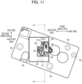
- Fig. 11 shows the jig 50 with the holder assembly 20 mounted thereon.
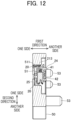
- Fig. 12 is a cross-sectional view of the jig 50 taken along a line D-D shown in Fig. 11 .
- Fig. 13 is a side view of the jig 50 with the gear cover 18 and holder assembly 20 mounted thereon.
- Fig. 14 is a cross-sectional view of the jig 50, holder assembly 20, and gear cover 18 taken along a line E-E shown in Fig. 13 .
- the jig 50 is used in a process of removing the holder assembly 20 mounted on the gear cover 18 from the gear cover 18 and in a process of mounting the holder assembly 20 on the gear cover 18. As illustrated in Figs. 8 through 10 , the jig 50 has a first recess 51, and a plurality of protrusions 53.
- the first recess 51 is recessed toward the one side in the first direction. As illustrated in Figs. 11 and 12 , the holder assembly 20 alone (for example, a new holder assembly 20) can be inserted into the first recess 51. Further, as illustrated in Figs. 13 and 14 , the holder assembly 20 mounted on the gear cover 18 can be inserted into the first recess 51.
- the first recess 51 has a first inner surface 511, and a second inner surface 512.
- the second inner surface 512 is positioned apart from the first inner surface 511 in the second direction.
- the second inner surface 512 is positioned on the other side of the first inner surface 511 to be separated apart therefrom in the second direction.
- the first inner surface 511 contacts the one end of the first holder 41 in the second direction when the holder assembly 20 is positioned in the first recess 51.
- the second inner surface 512 contacts the other end of the first holder 41 in the second direction. Since the first inner surface 511 and second inner surface 512 contact the first holder 41, the first holder 41 is suppressed from moving in the second direction.
- both the one end and the other end of the first holder 41 in the third direction contact inner surfaces of the first recess 51, thereby suppressing the first holder 41 from moving in the third direction within the first recess 51.
- the inner surfaces of the first recess 51 are shaped to conform to an outer profile of the holder cover 25.
- outer surfaces of the holder cover 25 contacts the inner surfaces of the first recess 51, whereby the holder cover 25 is immovably mounted on the jig 50.
- the first electrical contact surfaces 213 held by the first holder 41 are positioned apart from the first inner surface 511. As such, the first electrical contact surfaces 213 are restrained from rubbing against the jig 50.
- the second holder 42 is positioned apart from the inner surfaces of the first recess 51 in the second direction. Since the second holder 42 is positioned apart from the jig 50 in the second direction, the holder assembly 20 can be easily mounted on the jig 50.
- the jig 50 has a through-hole 513.
- the through-hole 513 penetrates through the jig 50 in the first direction.
- the through-hole 513 is located within the first recess 51.
- a tip end of the first boss 411 of the first holder 41 is positioned inside the through-hole 513.
- the through-hole 513 has an inner diameter that is larger than an outer diameter of the first boss 411. Hence, the first boss 411 is restricted from making contact with the jig 50.
- the jig 50 has five protrusions 53.
- the five protrusions 53 extend in the first direction.
- an outer peripheral surface of the gear cover 18 is in contact with the five protrusions 53. Due to the contact of the gear cover 18 with the protrusions 53, the gear cover 18 can be fixed in position relative to the jig 50 in the second direction or in the third direction. Further, the gear cover 18 is restrained from moving relative to the jig 50 in the second direction or in the third direction.
- Fig. 15 is a flowchart illustrating steps in a recycling procedure for the developing cartridge 10 using the jig 50.
- the recycling procedure illustrated in Fig. 15 includes a procedure for replacing the holder assembly 20 (steps S12-S17), and a procedure for replacing the gears and the developing roller 12 (steps S21-S25).
- the gear cover 18 is removed from the housing 11 of the developing cartridge 10 (step S11).
- the gear cover 18 is removed from the housing 11 after the screws are removed.
- the gear cover 18 is mounted on the jig 50 (step S12). Specifically, the holder assembly 20 mounted on the gear cover 18 is placed inside the first recess 51 of the jig 50, as illustrated in Figs. 13 and 14 . Inside the first recess 51, the one end of the first holder 41 in the holder assembly 20 contacts the first inner surface 511 of the first recess 51 while the other end of the first holder 41 contacts the second inner surface 512 of the first recess 51 (see Fig. 8 ). Hence, the first holder 41 is restricted from moving in the second direction relative to the jig 50. Further, the outer peripheral surface of the gear cover 18 contacts the five protrusions 53, whereby the gear cover 18 is restrained from moving in the second direction relative to the jig 50.
- step S12 the holder assembly 20 is removed from the gear cover 18 (step S13). As illustrated in Fig. 13 , the holder assembly 20 and gear cover 18 are assembled together by the first screw 253. In step S12, the holder assembly 20 is removed from the gear cover 18 by removing the first screw 253.
- the gear cover 18 has the first screw hole 61 in which the first screw 253 can be inserted.
- the holder cover 25 of the holder assembly 20 has the second screw hole 62 in which the first screw 253 can be inserted.
- step S12 the holder assembly 20 is positioned in the first recess 51 of the jig 50. Therefore, the operator is less likely to contact the electrical contact surfaces 213 of the IC chip 21 in the holder assembly 20 when removing the holder assembly 20 from the gear cover 18 in step S13. Accordingly, the IC chip 21 can be protected.
- the gear cover 18 can be mounted on the jig 50 even in a state where the holder assembly 20 protrudes from the gear cover 18.
- the holder assembly 20 is mounted on the jig 50 in step S12, the first holder 41 and gear cover 18 are restricted from moving relative to the jig 50. Accordingly, the first screw 253 can be easily removed in step S13, thereby facilitating the operation for removing the gear cover 18.
- Fig. 16 is a perspective view illustrating how the gear cover 18 is removed from the holder assembly 20. As illustrated in Fig. 16 , after the first screw 253 is removed, the gear cover 18 is separated from the jig 50 toward the other side in the first direction. As a result, the gear cover 18 is removed from the holder assembly 20 and the jig 50 while leaving the holder assembly 20 in the first recess 51 of the jig 50.
- step S13 the holder assembly 20 is removed from the first recess 51 of the jig 50 (step S14).
- step S15 the IC chip 21 held in the holder assembly 20 that was removed from the first recess 51 is replaced with a new or recycled IC chip 21 (step S15).
- a new IC chip 21 is a newly manufactured IC chip 21 that has not yet been used.
- a recycled IC chip 21 is a used IC chip 21, such as an IC chip 21 that has had information stored in the developing memory 211 updated.
- the holder assembly 20 with the replaced IC chip 21 differs from the holder assembly 20 that was removed from the gear cover 18 in step S13.
- the holder assembly 20 having the replaced IC chip 21 is an example of "another holder assembly.”
- the IC chip holder 24 of the holder assembly 20 may be replaced with a new or recycled IC chip holder 24 in step S15.
- the holder cover 25 of the holder assembly 20 may be replaced with a new or recycled holder cover 25.
- the IC chip 21, IC chip holder 24, and holder cover 25 may be replaced with new or recycled products.
- the holder assembly 20 is placed inside the first recess 51 of the jig 50 (step S16).
- the holder assembly 20 is positioned in the first recess 51, as illustrated in Figs. 11 and 12 , the one end of the first holder 41 contacts the first inner surface 511 while the other end of the first holder 41 contacts the second inner surface 512, whereby the IC chip holder 24 is mounted on the jig 50 so as to be immovable relative thereto.
- Fig. 17 is a perspective view illustrating how a new or recycled holder assembly 20 is mounted on the gear cover 18.
- the gear cover 18 is mounted on the jig 50 in step S17.
- the gear cover 18 is positioned on the other side of the holder assembly 20 in the first direction.
- the holder assembly 20 is then mounted on the gear cover 18 on the inner surface thereof with the first screw 253.
- the gear cover 18 is mounted on the jig 50 in step S17 while the holder assembly 20 is mounted on the jig 50. Accordingly, the operator can be restrained from contacting the first electrical contact surfaces 213 of the IC chip 21 in the holder assembly 20 while mounting the holder assembly 20 on the gear cover 18 in step S18. Thus, the IC chip 21 can be protected.
- step S17 the IC chip holder 24 of the holder assembly 20 is immovably mounted on the jig 50 and the gear cover 18 is immovably mounted on the jig 50. Therefore, the IC chip holder 24 and holder cover 25 can be fixed in position relative to the gear cover 18. In other words, the position of the first screw hole 61 formed in the gear cover 18 and the position of the second screw hole 62 formed in the holder cover 25 can be aligned with each other. A such, the gear cover 18 and holder assembly 20 can be easily mounted on each other with the first screw 253.
- step S21 the gears are removed from the developing cartridge 10 (step S21).
- the gears include the developing roller gear 123, supply roller gear 133, first idle gear 171, second idle gear 172, third idle gear 173, first agitator gear 145, and second agitator gear 155.
- step S21 the gears coupled to the developing roller 12 are removed.
- step S21 the developing roller 12 is removed from the developing cartridge 10 (step S22).
- step S22 maintenance is performed (step S23). Specifically, cleaning on the developing roller 12 is performed in step S23.
- a thickness regulating blade may also be cleaned or replaced.
- the thickness regulating blade is a member for making the toner deposited on the surface of the developing roller 12 into a uniform layer.
- a toner seal may also be replaced in step S23.
- the toner seal is a member that suppresses leakage of toner from the housing 11 of an unused developing cartridge 10.
- the developing roller 12 is mounted on the housing 11 (step S24).
- the developing roller 12 that is mounted on the housing 11 may be the developing roller 12 that was removed in step S22 and cleaned in step S23.
- the developing roller 12 may be a new or recycled developing roller 12.
- step S24 the gears are mounted on the housing 11 (step S25).
- the gears mounted in step S25 may be new or recycled gears.
- step S17 the gear cover 18 having the holder assembly 20 mounted thereon is mounted on the housing 11 (step S18). This completes the process of recycling the holder assembly 20.
- the jig 50 is used for removing the holder assembly 20 (step S13) and for mounting the holder assembly 20 (step S17).
- This configuration can refrain the operator from contacting the first electrical contact surfaces 213 of the IC chip 21 in the holder assembly 20. Therefore, the IC chip 21 can be suitably protected in recycling of the developing cartridge 10.
- the first recess 51 may be formed as a through-hole without a bottom.
- the number of the protrusions 53 is not limited to five, but may be four or less, or six or more.
Landscapes
- Physics & Mathematics (AREA)
- General Physics & Mathematics (AREA)
- Engineering & Computer Science (AREA)
- Computer Vision & Pattern Recognition (AREA)
- Life Sciences & Earth Sciences (AREA)
- Sustainable Development (AREA)
- Manufacturing & Machinery (AREA)
- Computer Networks & Wireless Communication (AREA)
- Dry Development In Electrophotography (AREA)
- Electrophotography Configuration And Component (AREA)
Abstract
Description
- The present disclosure relates to a method of recycling developing cartridges.
- Patent Document 1 describes a developing cartridge (1) that can be mounted on a drum cartridge (2). The developing cartridge (1) has an IC chip (18), which is a storage medium; an IC chip holder that holds the IC chip; and a holder cover that holds the IC chip holder. The IC chip (18) stores various information about the developing cartridge (1) (for example, information on the service life of components such as a developing roller (13)). The holder cover is fixed to a gear cover (152). Further, the gear cover (152) is fixed to an end of a casing (11) that can store toner.
- [PTL 1]
Japanese Patent Application Publication No. 2021-162749 - In recent years, some developing cartridges have been recycled from the standpoint of promoting environmental protection and the sustainable use of resources. To recycle a developing cartridge, the developing cartridge is disassembled and necessary maintenance is performed, such as replacing or cleaning parts in the developing cartridge. For example, the IC chip, IC chip holder, and holder cover in the developing cartridge may be replaced when recycling the cartridge.
- However, when an operator replaces the IC chip, IC chip holder, and holder cover in a developing cartridge, the IC chip holder could move relative to the holder cover. Consequently, the operator may have difficulty in fixing the holder cover to the gear cover while the holder cover retains the IC chip holder. Therefore, a technology is needed for facilitating he operator's mounting of a holder cover retaining an IC chip holder on a gear cover in recycling a developing cartridge.
- An object of the present disclosure is to provide a technique for facilitating mounting of a holder cover holding an IC chip holder on a gear cover in recycling of a developing cartridge.
- In order to solve the above problem, a first aspect provides a method of recycling a developing cartridge including: a housing configured to store developer therein; a gear cover positioned at one end of the housing in a first direction; a holder assembly; and a first screw for mounting the holder assembly on the gear cover, wherein the holder assembly includes: a storage medium; a storage medium holder holding the storage medium, the storage medium holder being movable relative to the housing and the gear cover; and a holder cover holding the storage medium holder. The method includes: a gear cover removing step of removing the gear cover having the holder assembly mounted thereon with the first screw from the housing; a screw removing step of removing, after the gear cover removing step, the first screw from the gear cover; a holder assembly removing step of removing, after the screw removing step, the holder assembly from the gear cover; a first gear cover mounting step of mounting, after the holder assembly removing step, the gear cover on a jig on which another holder assembly different from the removed holder assembly is mounted; a holder assembly mounting step of mounting, after the first gear cover mounting step, the another holder assembly on the gear cover with the first screw; and a second gear cover mounting step of mounting, after the holder assembly mounting step, the gear cover having the another holder assembly mounted thereon with the first screw on the housing. In the first gear cover mounting step, a storage medium holder of the another holder assembly is restricted from moving relative to the jig and a holder cover of the another holder assembly in a state where the another holder assembly is mounted on the jig.
- A second aspect is the method of recycling the developing cartridge according to the first aspect, in which, in the first gear cover mounting step, the storage medium holder of the another holder assembly is immovable relative to the jig and the holder cover of the another holder assembly in the state where the another holder assembly is mounted on the jig.
- A third aspect is the method of recycling the developing cartridge according to the first aspect or the second aspect, in which, the another holder assembly includes: another storage medium different from the storage medium of the holder assembly; another storage medium holder holding the storage medium, the another storage medium holder being different from the storage medium holder of the holder assembly; and another holder cover holding the another storage medium holder, the another holder cover being different from the holder cover of the holder assembly. In the first gear cover mounting step, the another storage medium holder is immovably mounted on the jig.
- A fourth aspect is the method of recycling the developing cartridge according to any one of the first to third aspects, in which: the jig has a first recess that is recessed in the first direction; and, in the first gear cover mounting step, the another holder assembly is mounted in the first recess.
- A fifth aspect is the method of recycling the developing cartridge according to any one of the first to fourth aspects, in which: the jig has a plurality of protrusions extending in the first direction; and, in the first gear cover mounting step, an outer peripheral surface of the gear cover contacts the plurality of protrusions.
- A sixth aspect is the method of recycling the developing cartridge according to any one of the first to fifth aspects, in which: the gear cover has a first screw hole in which the first screw can be inserted; the holder cover has a second screw hole in which the first screw can be inserted; and, in the holder assembly mounting step, the first screw is inserted into the first screw hole and the second screw hole from an inner surface of the gear cover in the first direction toward an outer surface of the gear cover in the first direction.
- A seventh aspect is the method of recycling the developing cartridge according to any one of the first to sixth aspects, in which: the storage medium holder includes a first holder holding the storage medium, a second holder positioned apart from the first holder in a second direction crossing the first direction, and a resilient member positioned between the first holder and the second holder and configured to expand and contract in the second direction; the jig has a first inner surface and a second inner surface positioned apart from the first inner surface in the second direction; the first inner surface contacts one end portion of the first holder in the second direction; and the second inner surface contacts another end portion of the first holder in the second direction.
- An eighth aspect is the method of recycling the developing cartridge according to any one of the first to seventh aspects, in which: the storage medium has an electrical contact surface; and, in the first gear cover mounting step, the electrical contact surface is positioned apart from the first inner surface.
- A ninth aspect is the method of recycling the developing cartridge according to any one of the first to eighth aspects, in which: in a case where the holder assembly is mounted on the jig by the gear cover removing step, another end portion of the second holder is positioned apart from the jig in the second direction.
- A tenth aspect is a method of recycling a developing cartridge including: a housing configured to store developer therein; a gear cover positioned at one end of the housing in a first direction; a holder assembly; and a first screw for mounting the holder assembly on the gear cover, wherein the holder assembly includes: a storage medium having an electrical contact surface; a storage medium holder holding the storage medium, the storage medium holder being movable relative to the housing and the gear cover; and a holder cover holding the storage medium holder. The method includes: a first gear cover removing step of removing the gear cover having the holder assembly mounted thereon with the first screw from the housing; a first holder assembly mounting step of mounting, after the first gear cover removing step, the holder assembly mounted on the gear cover with the first screw on a jig; a screw removing step of removing, after the first holder assembly mounting step, the first screw from the gear cover; and a second gear cover removing step of removing, after the screw removing step, the gear cover from the holder assembly while leaving the holder assembly on the jig. In the first holder assembly mounting step, the storage medium holder of the holder assembly is restricted from moving relative to the jig and the holder cover of the holder assembly in a state where the holder assembly is mounted on the jig.
- An eleventh aspect is the method of recycling the developing cartridge according to any one of the tenth aspect, in which: the jig has a plurality of protrusions extending in the first direction; and in the first holder assembly mounting step, an outer peripheral surface of the gear cover contacts the plurality of protrusions.
- A twelfth aspect is the method of recycling the developing cartridge according to the tenth aspect or the eleventh aspect, which further includes: a first holder assembly removing step of removing, after the screw removing step, the holder assembly from the jig; a second holder assembly mounting step of mounting, after the first holder assembly removing step, another holder assembly different from the removed holder assembly on the jig; a gear cover mounting step of mounting, after the second holder assembly mounting step, the gear cover on the jig; and a third holder assembly mounting step of mounting, after the gear cover mounting step, the another holder assembly on the gear cover with the first screw.
- A thirteenth aspect is the method of recycling the developing cartridge according to the tenth aspect or the eleventh aspect, which further includes: a first holder assembly removing step of removing, after the screw removing step, the holder assembly from the jig; a storage medium removing step of removing, after the first holder assembly removing step, the storage medium from the storage medium holder; a storage medium mounting step of mounting, after the storage medium removing step, another storage medium different from the removed storage medium on the storage medium holder; a second holder assembly mounting step of mounting, after the storage medium mounting step, the storage medium holder having the another storage medium mounted thereon and the holder cover on the jig; a gear cover mounting step of mounting, after the second holder assembly mounting step, the gear cover on the jig; and a holder cover mounting step of mounting, after the gear cover mounting step, the holder cover on the gear cover with the first screw.
- A fourteenth aspect is the method of recycling the developing cartridge according to any one of the first to thirteenth aspects, in which: the developing cartridge further includes a developing roller rotatable about a developing roller axis extending in the first direction. The method further includes: a developing roller removing step of removing, after the first gear cover removing step, the developing roller from the housing; and a developing roller mounting step of mounting, after the developing roller removing step, another developing roller different from the removed developing roller on the housing.
- A fifteenth aspect is the method of recycling the developing cartridge according to any one of the first to fourteenth aspects, in which: the developing cartridge further includes: an agitator rotatable about an agitator axis extending in the first direction; and an agitator gear rotatable about the agitator axis together with the agitator. The method further includes: an agitator gear removing step of removing, after the first gear cover removing step, the agitator gear from the housing; and an agitator gear mounting step of mounting, after the agitator gear removing step, another agitator gear different from the removed agitator gear on the housing.
- According to the method of recycling the developing cartridge of the first aspect, movement of the storage medium holder relative to the jig and the holder cover is restricted in a state where the another holder assembly is mounted on the jig. Therefore, the holder cover holding the storage medium holder can be easily mounted on the gear cover.
- According to the method of recycling the developing cartridge of the second aspect, the storage medium holder is immovable relative to the jig and the holder cover in a state where the another holder assembly is mounted on the jig. Therefore, the holder cover holding the storage medium holder can be easily mounted on the gear cover.
- According to the method of recycling the developing cartridge of the third aspect, since the another storage medium holder is mounted on the jig so as to be immovable relative thereto, a new storage medium holder can be easily mounted on the gear cover.
- According to the method of recycling the developing cartridge of the fourth aspect, the storage medium can be protected by the holder assembly that is positioned in the first recess of the jig.
- According to the method of recycling the developing cartridge of the fifth aspect, the holder assembly can be easily mounted on the gear cover since the gear cover is fixed in position by the plurality of protrusions.
- According to the method of recycling the developing cartridge of the sixth aspect, a decrease in clamping force of a first screw due to deformation of the second screw hole of the holder cover can be addressed by replacing the holder cover. Therefore, since the number of times the storage medium holder is replaced can be reduced, the cost of recycling the developing cartridge can be reduced.
- According to the method of recycling the developing cartridge of the seventh aspect, the first holder can be made immovable in the second direction upon mounting of the holder assembly on the jig.
- According to the method of recycling the developing cartridge of the eighth aspect, the electrical contact surface of the storage medium can be suppressed from contacting the first inner surface of the jig.
- According to the method of recycling the developing cartridge of the ninth aspect, the holder assembly can be easily mounted on the jig.
- According to the method of recycling the developing cartridge of the tenth aspect, movement of the storage medium holder relative to the jig and the holder cover is restricted in a state where the another holder assembly is mounted on the jig. Therefore, the holder cover holding the storage medium holder can be easily mounted on the gear cover.
- According to the method of recycling the developing cartridge of the eleventh aspect, the holder assembly can be easily removed from the gear cover since the gear cover can be fixed in position by the plurality of protrusions.
- According to the method of recycling the developing cartridge of the thirteenth aspect, the storage medium can be replaced with another storage medium.
- According to the method of recycling the developing cartridge of the fourteenth aspect, the developing roller can be replaced with a new developing roller.
- According to the method of recycling the developing cartridge of the fifteenth aspect, the agitator gear can be replaced with a new agitator gear.
-
- [
Fig. 1] Fig. 1 is a perspective view of a developing cartridge according to the embodiment. - [
Fig. 2] Fig. 2 is a side view of the developing cartridge according to the embodiment. - [
Fig. 3] Fig. 3 is a central cross-sectional view of the developing cartridge according to the embodiment. - [
Fig. 4] Fig. 4 is a side view illustrating the developing cartridge in a state where agear cover 18 is removed. - [
Fig. 5] Fig. 5 is a bottom view illustrating one end of the developing cartridge in a first direction. - [
Fig. 6] Fig. 6 is a perspective view of an IC chip holder according to the embodiment. - [
Fig. 7] Fig. 7 is a cross-sectional view of the IC chip holder taken along a line A-A shown inFig. 6 . - [
Fig. 8] Fig. 8 is a side view of a jig according to the embodiment. - [
Fig. 9] Fig. 9 is a cross-sectional view of the jig taken along a line B-B shown inFig. 8 . - [
Fig. 10] Fig. 10 is a cross-sectional view of the jig taken along a line C-C shown inFig. 8 . - [
Fig. 11] Fig. 11 illustrates the jig with a holder assembly mounted thereon. - [
Fig. 12] Fig. 12 is a cross-sectional view of the jig taken along a line D-D shown inFig. 11 . - [
Fig. 13] Fig. 13 is a side view of the jig with the gear cover and holder assembly mounted thereon. - [
Fig. 14] Fig. 14 is a cross-sectional view of the jig, holder assembly, and gear cover taken along a line E-E shown inFig. 13 . - [
Fig. 15] Fig. 15 is a flowchart illustrating a procedure for recycling the developing cartridge using the jig. - [
Fig. 16] Fig. 16 is a perspective view illustrating how the gear cover is removed from the holder assembly. - [
Fig. 17] Fig. 17 is a perspective view illustrating how a new or recycled holder assembly is fixed to the gear cover. - Hereinafter, an embodiment of the present disclosure will be described while referring to accompanying drawings. Incidentally, the components described in this embodiment are merely examples, and the scope of this disclosure is not intended to be limited to these examples. In the drawings, dimensions and numbers of components may be simplified as necessary for facilitating understanding.
-
Fig. 1 is a perspective view of a developingcartridge 10 according to the embodiment.Fig. 2 is a side view of the developingcartridge 10 illustrated inFig. 1 .Fig. 3 is a central cross-sectional view of the developingcartridge 10 illustrated inFig. 1 .Fig. 4 is a side view illustrating the developingcartridge 10 in a state where agear cover 18 is removed.Fig. 5 is a bottom view illustrating one end of the developingcartridge 10 in a first direction.Fig. 6 is a perspective view of anIC chip holder 24 according to the embodiment.Fig. 7 is a cross-sectional view of theIC chip holder 24 taken along a line A-A shown inFig. 6 . - Hereinafter, a direction in which a developing roller axis A12 of a developing
roller 12 in the developingcartridge 10 extends will be called "first direction." A direction crossing a firstelectrical contact surface 213 provided in the developingcartridge 10 will be called "second direction." A direction in which the developingroller 12 and a first agitator 14 (Fig. 3 ) are aligned will be called "third direction." The first, second, and third directions all cross each other and, are preferably all orthogonal to each other. - As illustrated in
Fig. 1 , the developingcartridge 10 includes ahousing 11, the developingroller 12, asupply roller 13, thefirst agitator 14, and asecond agitator 15. - The
housing 11 can accommodate developer therein. The developer is toner, for example. Thehousing 11 extends in the first direction. Thehousing 11 has an opening 110 (seeFig. 4 ). Theopening 110 is positioned at one end of thehousing 11 in the third direction. Thehousing 11 has afirst handle 113. Thefirst handle 113 is positioned at another end of thehousing 11 in the third direction. Thehousing 11 has a firstouter surface 115, and a secondouter surface 116. The firstouter surface 115 is positioned at one end of thehousing 11 in the second direction. The secondouter surface 116 is positioned at another end of thehousing 11 in the second direction. - The developing
roller 12 is rotatable about the developing roller axis A12 in a state where the developingcartridge 10 is attached to a body of a printer. The developing roller axis A12 extends in the first direction. The developingroller 12 is positioned in theopening 110. In other words, the developingroller 12 is positioned at the one end of thehousing 11 in the third direction. In a state where the developingcartridge 10 is attached to the printer body, the developingroller 12 supplies the developer in thehousing 11 onto a surface of a photosensitive drum (not illustrated). - The developing
roller 12 includes a developingroller body 121, and a developingroller shaft 122. The developingroller body 121 has a cylindrical shape that extends in the first direction. The developingroller body 121 is configured of an electrically-conductive rubber, for example. - The developing
roller shaft 122 has a columnar shape that extends along the developing roller axis A12. The developingroller shaft 122 is made of metal, for example. The developingroller shaft 122 is positioned radially inside the developingroller body 121. The developingroller shaft 122 penetrates through the developingroller body 121 in the first direction. Incidentally, the developingroller shaft 122 need not penetrate the developingroller body 121, but may be mounted in both ends of the developingroller body 121. The developingroller 12 is rotatable about the developingroller shaft 122. - The
supply roller 13 supplies the developer within thehousing 11 onto a surface of the developingroller 12. Thesupply roller 13 is positioned inside thehousing 11. Thesupply roller 13 contacts the developingroller 12. Thesupply roller 13 is rotatable about a supply roller axis. The supply roller axis extends in the first direction. - As illustrated in
Fig. 3 , thesupply roller 13 includes asupply roller body 131, and asupply roller shaft 132. Thesupply roller body 131 has a cylindrical shape that extends in the first direction. Thesupply roller body 131 is configured of an electrically-conductive sponge, for example. Thesupply roller body 131 contacts the developingroller body 121. - The
first agitator 14 can agitate developer. As illustrated inFig. 3 , thefirst agitator 14 is positioned inside thehousing 11. Thefirst agitator 14 is rotatable about an agitator axis A14. The agitator axis A14 extends in the first direction. As illustrated inFig. 3 , thefirst agitator 14 includes anagitator shaft 141, and afilm 143. - The
agitator shaft 141 extends along the agitator axis A14. Thefilm 143 is coupled to theagitator shaft 141. Theagitator shaft 141 andfilm 143 are rotatable about the agitator axis A14. By rotating, thefilm 143 agitates the developer inside thehousing 11. Thefilm 143 is made of resin. - The
second agitator 15 can agitate developer. As illustrated inFig. 3 , thesecond agitator 15 is positioned inside thehousing 11. Thesecond agitator 15 is positioned on an opposite side of thefirst agitator 14 from the developingroller 12 in the third direction. Thesecond agitator 15 is rotatable about an agitator axis A15. The agitator axis A15 extends in the first direction. Thesecond agitator 15 includes anagitator shaft 151, and afilm 153. - The
agitator shaft 151 extends along the agitator axis A15. Thefilm 153 is coupled to theagitator shaft 151. Theagitator shaft 151 andfilm 153 are rotatable about the agitator axis A15. By rotating, thefilm 153 agitates the developer inside thehousing 11. Thefilm 153 is made of resin, for example. - As illustrated in
Figs. 2 and4 , the developingcartridge 10 further includes a developingcoupling 16, a developingroller gear 123, asupply roller gear 133, a firstidle gear 171, a secondidle gear 172, a thirdidle gear 173, afirst agitator gear 145, asecond agitator gear 155, thegear cover 18, and aholder assembly 20. - As illustrated in
Fig. 4 , the developingcoupling 16 is positioned at one end of thehousing 11 in the first direction. The developingcoupling 16 is positioned between the developingroller 12 and thefirst agitator 14 in the third direction. The developingcoupling 16 is rotatable about a coupling axis A16. The coupling axis A16 extends in the first direction. The developingcoupling 16 has acoupling part 161, and acoupling gear 162. Thecoupling part 161 andcoupling gear 162 may be integral or separate parts. Thecoupling part 161 has a coupling hole that is recessed in the first direction. - In a state where the developing
cartridge 10 is attached to the printer body (not illustrated), thecoupling part 161 receives power from the printer body. When engaged with a device-side coupling (not illustrated) of the printer body, thecoupling part 161 can rotate together with the device-side coupling about the coupling axis A16. Thecoupling part 161 has a cylindrical shape that extends in the first direction. Thecoupling gear 162 is positioned at the one end of thehousing 11 in the first direction. Thecoupling gear 162 can rotate together with thecoupling part 161. - As illustrated in
Fig. 4 , the developingroller gear 123 is positioned at the one end of thehousing 11 in the first direction. The developingroller gear 123 is attached to the developingroller shaft 122 and is rotatable together with the developingroller shaft 122. The developingroller gear 123 meshes with thecoupling gear 162. - As illustrated in
Fig. 4 , thesupply roller gear 133 is positioned at the one end of thehousing 11 in the first direction. Thesupply roller gear 133 is attached to thesupply roller shaft 132 and is rotatable together with thesupply roller shaft 132. Thesupply roller gear 133 meshes with thecoupling gear 162. - As illustrated in
Fig. 4 , the firstidle gear 171 is positioned at the one end of thehousing 11 in the first direction. The firstidle gear 171 is positioned between the secondidle gear 172 and thehousing 11 in the first direction. The firstidle gear 171 is rotatable about an idle axis A17 extending in the first direction. The firstidle gear 171 meshes with thecoupling gear 162. - As illustrated in
Fig. 4 , the secondidle gear 172 is positioned at the one end of thehousing 11 in the first direction. The secondidle gear 172 is positioned farther from thehousing 11 in the first direction than the firstidle gear 171 is from thehousing 11 in the first direction. The secondidle gear 172 is positioned on an opposite side of the firstidle gear 171 from the one end of thehousing 11 in the first direction. The secondidle gear 172 has a diameter that is smaller than a diameter of the firstidle gear 171. The firstidle gear 171 is rotatable together with the secondidle gear 172 about the idle axis A17. The firstidle gear 171 and secondidle gear 172 rotate together. The firstidle gear 171 and second idle gear may be formed integrally or separately from each other. - As illustrated in
Fig. 4 , the thirdidle gear 173 is positioned at the one end of thehousing 11 in the first direction. The thirdidle gear 173 is positioned between a small-diameter gear 149 (seeFig. 5 ) of thefirst agitator gear 145 described later and thesecond agitator gear 155 in the third direction. The thirdidle gear 173 is rotatable about an idle axis A173. The thirdidle gear 173 meshes with the small-diameter gear 149 of thefirst agitator gear 145. - As illustrated in
Fig. 4 , thefirst agitator gear 145 is positioned at the one end of thehousing 11 in the first direction. Thefirst agitator gear 145 is attached to theagitator shaft 141 of thefirst agitator 14. Thefirst agitator gear 145 is rotatable together with thefirst agitator 14 about the agitator axis A14. - The
first agitator gear 145 has a large-diameter gear 147, and the small-diameter gear 149. The small-diameter gear 149 has a diameter that is smaller than a diameter of the large-diameter gear 147. As illustrated inFig. 5 , the small-diameter gear 149 is positioned between the large-diameter gear 147 and thehousing 11 in the first direction. In other words, the large-diameter gear 147 is positioned on an opposite side of the small-diameter gear 149 from thehousing 11 in the first direction. - As illustrated in
Fig. 4 , thesecond agitator gear 155 is positioned at the one end of thehousing 11 in the first direction. Thesecond agitator gear 155 is attached to theagitator shaft 151 of thesecond agitator 15. Thesecond agitator gear 155 can rotate together with thesecond agitator 15 about the agitator axis A15. Thesecond agitator gear 155 meshes with the thirdidle gear 173. - As illustrated in
Figs. 2 and4 , thegear cover 18 covers thecoupling gear 162,supply roller gear 133, firstidle gear 171, secondidle gear 172, thirdidle gear 173,first agitator gear 145, andsecond agitator gear 155. Incidentally, thegear cover 18 may cover just some of the gears and need not cover all gears. Thegear cover 18 is mounted on the one end of thehousing 11 in the first direction by screws or the like. - The
holder assembly 20 includes anIC chip 21, anIC chip holder 24, and aholder cover 25. As illustrated inFigs. 1 and2 , theholder assembly 20 is positioned at one end of thegear cover 18 in the first direction. - The
IC chip 21 is an example of a "storage medium." As illustrated inFig. 6 , theIC chip 21 has a developingmemory 211, anIC substrate 212, and first electrical contact surfaces 213. The developingmemory 211 stores various information on the developingcartridge 10. For example, the developingmemory 211 stores ID information, and service life information. The ID information is information for identifying an individual developingcartridge 10. Specifically, the ID information is a serial number. The service life information includes the cumulative number of rotations of the developingroller 12, the cumulative number of sheets printed using the developingroller 12, and the cumulative number of dots printed using the developingroller 12, for example. - The
IC substrate 212 is positioned at one end of theIC chip holder 24 in the second direction. TheIC substrate 212 is a plate-shaped member. - The first electrical contact surfaces 213 are positioned on one end of the
IC substrate 212 in the second direction. The first electrical contact surfaces 213 include four thin plate-like electrodes. The first electrical contact surfaces 213 are electrically connected to the developingmemory 211. In a state where the developingcartridge 10 is attached to the printer body, the first electrical contact surfaces 213 are parallel to the third direction. The first electrical contact surfaces 213 can move, relative to thehousing 11, in the first, second, and third directions. - The
IC chip holder 24 is an example of a "storage medium holder." As illustrated inFig. 1 , theIC chip holder 24 is positioned at the one end of thehousing 11 in the first direction. As illustrated inFig. 2 , theIC chip holder 24 is positioned between the developingroller 12 and thefirst handle 113 in the third direction. As illustrated inFig. 4 , at least a portion of theIC chip holder 24 overlaps the large-diameter gear 147 in the first direction. In other words, at least a portion of theIC chip holder 24 is positioned in an area in which the large-diameter gear 147 is projected in the first direction. As illustrated inFig. 4 , theIC chip holder 24 is positioned between the firstouter surface 115 and the secondouter surface 116 of thehousing 11 in the second direction. - The
IC chip holder 24 holds the first electrical contact surfaces 213 by holding theIC substrate 212. As illustrated inFig. 6 , theIC chip holder 24 has a firstouter surface 413 positioned on one end thereof in the second direction. The firstouter surface 413 has a recessed shape into which theIC substrate 212 can be inserted. TheIC substrate 212 is affixed to the firstouter surface 413 with an adhesive material, for example. The firstouter surface 413 can retain theIC chip 21. In other words, the firstouter surface 413 can hold the developingmemory 211 and first electrical contact surfaces 213 by holding theIC chip 21. - As illustrated in
Fig. 1 , theholder cover 25 is positioned at the one end of thegear cover 18 in the first direction. Theholder cover 25 has a generally square cylindrical shape that, together with thegear cover 18, surrounds theIC chip holder 24. As illustrated inFig. 5 , theholder cover 25 has a U-shape that surrounds one end of theIC chip holder 24 in the first direction, one end of theIC chip holder 24 in the third direction, and another end of theIC chip holder 24 in the third direction. Theholder cover 25 holds theIC chip holder 24. TheIC chip holder 24 is movable, relative to theholder cover 25, in the first, second, and third directions. - As illustrated in
Fig. 5 , theholder cover 25 has afirst plate part 251. Thefirst plate part 251 is positioned away from thegear cover 18 toward the one side in the first direction. TheIC chip holder 24 is positioned between thefirst plate part 251 and thegear cover 18 in the first direction. - As illustrated in
Fig. 5 , theholder cover 25 is mounted on thegear cover 18 by afirst screw 253. Thefirst screw 253 is inserted into a first screw hole 61 (seeFig. 13 ) of thegear cover 18 and a second screw hole 62 (seeFig. 11 ) of theholder cover 25 from an inner surface of thegear cover 18 in the first direction toward an outer surface of thegear cover 18 in the first direction. Theholder cover 25 may also be mounted on thegear cover 18 with two or morefirst screws 253. - As illustrated in
Figs. 2 and5 , theholder cover 25 has a first through-hole 254. As illustrated inFig. 5 , thegear cover 18 has a second through-hole 255, and a third through-hole 256. The first through-hole 254 is positioned in thefirst plate part 251. The first through-hole 254 extends toward the one side in the second direction as extending toward the one side in the third direction. The second through-hole 255 and third through-hole 256 may have the same shape as the first through-hole 2540, or a different shape from the first through-hole 254. - The
IC chip holder 24 is movable relative to thehousing 11. The first electrical contact surfaces 213 retained by theIC chip holder 24 are also movable relative to thehousing 11. TheIC chip holder 24 is movable relative to thegear cover 18. - As illustrated in
Fig. 6 , theIC chip holder 24 has afirst boss 411, asecond boss 412, and athird boss 417. Thefirst boss 411,second boss 412, andthird boss 417 extend in the first direction. Thefirst boss 411 is positioned at the one end of theIC chip holder 24 in the first direction. Thesecond boss 412 andthird boss 417 are positioned at another end of theIC chip holder 24 in the first direction. Thethird boss 417 is positioned apart from thesecond boss 412 toward the one side in the second direction. Thefirst boss 411 is positioned between thesecond boss 412 and thethird boss 417 in the second direction. - The
first boss 411 is loosely inserted in the first through-hole 254. Thesecond boss 412 is loosely inserted in the second through-hole 255. Thethird boss 417 is loosely inserted in the third through-hole 256. As illustrated inFig. 2 , the first through-hole 254 has a size in the second direction that is larger than a size in the second direction of thefirst boss 411. When theIC chip holder 24 moves relative to theholder cover 25 in the second direction, thefirst boss 411 moves in the second direction within the first through-hole 254. The second through-hole 255 has a size in the second direction that is larger than a size in the second direction of thesecond boss 412. When theIC chip holder 24 moves relative to theholder cover 25 in the second direction, thesecond boss 412 moves in the second direction within the second through-hole 255. - As illustrated in
Fig. 2 , the first through-hole 254 also extends in the third direction. The first through-hole 254 has a size in the third direction that is larger than a size in the third direction of thefirst boss 411. When theIC chip holder 24 moves relative to theholder cover 25 in the third direction, thefirst boss 411 moves in the third direction within the first through-hole 254. Since thefirst boss 411 can move in the third direction within the first through-hole 254, theIC chip holder 24 can move in the third direction relative to thehousing 11. - Incidentally, the first through-
hole 254 may be in a form of a recess in which an end of thefirst boss 411 can be inserted. Likewise, the second through-hole 255 may be in a form of a recess in which an end of thesecond boss 412 can be inserted. Further, the third through-hole 256 may also be in a form of a recess in which an end of thethird boss 417 can be inserted. - As illustrated in
Fig. 6 , theIC chip holder 24 has aholder groove 414. Theholder groove 414 is positioned at the one end of theIC chip holder 24 in the second direction. TheIC chip holder 24 has aholder protrusion 415. Theholder protrusion 415 is positioned apart from the firstouter surface 413 in the first direction. Theholder groove 414 is positioned between the firstouter surface 413 and theholder protrusion 415 in the first direction. - As illustrated in
Figs. 6 and7 , theIC chip holder 24 has afirst holder 41, and asecond holder 42. Thesecond holder 42 is positioned apart from thefirst holder 41 on the other side of thefirst holder 41 in the second direction. The firstouter surface 413 is positioned on the one end of thefirst holder 41 in the second direction. Thefirst holder 41 has acylindrical part 416. Thecylindrical part 416 is positioned on the other end of thefirst holder 41 in the second direction. Thecylindrical part 416 has a square tubular shape that is elongated in the second direction. - As illustrated in
Figs. 6 and7 , thesecond holder 42 has abody portion 421, apawl 422, andprotrusions Fig. 7 , thebody portion 421 extends in the second direction. Thebody portion 421 has a square tubular shape. Thebody portion 421 has a bottom. The bottom is positioned at the other side of thebody portion 421 in the second direction. Thebody portion 421 is inserted inside thecylindrical part 416. Thesecond holder 42 is movable relative to thefirst holder 41 in the second direction. As illustrated inFig. 6 , a tip end of thepawl 422 is inserted in a through-hole formed in thecylindrical part 416 of thefirst holder 41. Accordingly, thesecond holder 42 is configured not to come off relative to thefirst holder 41. - The
protrusions body portion 421 toward the other side in the second direction. Theprotrusion 424 is positioned apart from theprotrusion 423 toward the other side in the first direction. In other words, theprotrusion 424 is positioned closer to the one end of theIC chip 21 in the first direction than theprotrusion 423 is to the other end of theIC chip 21. Theprotrusion 424 is positioned closer to thegear cover 18 in the first direction than theprotrusion 423 is to thegear cover 18. Theprotrusion 423 has acurved surface 426. Theprotrusion 424 has acurved surface 427. Thecurved surface 427 is positioned on the other side of thecurved surface 426 in the first direction. - The
curved surface 427 is positioned apart from thecurved surface 426 toward the other side in the first direction. In other words, thecurved surface 427 is positioned closer to the one end of thehousing 11 in the first direction than thecurved surface 426 is to the one end of thehousing 11. Thecurved surface 427 is positioned closer to thegear cover 18 in the first direction than thecurved surface 426 is to thegear cover 18. Thecurved surfaces outer surface 425. The secondouter surface 425 is positioned on the other end of theIC chip holder 24 in the second direction. The secondouter surface 425 has aholder groove 428. Theholder groove 428 is positioned between thecurved surface 426 and thecurved surface 427 in the first direction. - As illustrated in
Figs. 6 and7 , theIC chip holder 24 includes aresilient member 45. Theresilient member 45 is positioned between thefirst holder 41 andsecond holder 42 in the second direction. Theresilient member 45 is positioned between the firstouter surface 413 and secondouter surface 425. Theresilient member 45 is a coil spring, for example. - As illustrated in
Fig. 7 , theresilient member 45 is positioned inside thecylindrical part 416 of thefirst holder 41 and inside thebody portion 421 of thesecond holder 42. Theresilient member 45 has one end in the second direction that is in contact with thefirst holder 41. Theresilient member 45 has another end in the second direction that is in contact with thesecond holder 42. - The
resilient member 45 can expand and contract in the second direction. As theresilient member 45 expands and contracts, theIC chip holder 24 expands and contracts in the second direction. When theIC chip holder 24 contracts in the second direction, theresilient member 45 contracts in the second direction, thereby generating a resilient force (a restoring force). Through this resilient force, theresilient member 45 urges thesecond holder 42 in a direction away from the first holder 41 (toward the other side) in the second direction. - By the resilient force of the
resilient member 45, theIC chip holder 24 can bring the firstelectrical contact surface 213 into good contact with a device-side electrical contact in the printer body when the developingcartridge 10 is attached to the printer body. -
Fig. 8 is a side view of ajig 50 according to the embodiment.Fig. 9 is a cross-sectional view of thejig 50 taken along a line B-B shown inFig. 8 .Fig. 10 is a cross-sectional view of thejig 50 taken along a line C-C shown inFig. 8 .Fig. 11 shows thejig 50 with theholder assembly 20 mounted thereon.Fig. 12 is a cross-sectional view of thejig 50 taken along a line D-D shown inFig. 11 .Fig. 13 is a side view of thejig 50 with thegear cover 18 andholder assembly 20 mounted thereon.Fig. 14 is a cross-sectional view of thejig 50,holder assembly 20, and gear cover 18 taken along a line E-E shown inFig. 13 . - The
jig 50 is used in a process of removing theholder assembly 20 mounted on the gear cover 18 from thegear cover 18 and in a process of mounting theholder assembly 20 on thegear cover 18. As illustrated inFigs. 8 through 10 , thejig 50 has afirst recess 51, and a plurality ofprotrusions 53. - The
first recess 51 is recessed toward the one side in the first direction. As illustrated inFigs. 11 and12 , theholder assembly 20 alone (for example, a new holder assembly 20) can be inserted into thefirst recess 51. Further, as illustrated inFigs. 13 and14 , theholder assembly 20 mounted on thegear cover 18 can be inserted into thefirst recess 51. - The
first recess 51 has a firstinner surface 511, and a secondinner surface 512. As illustrated inFigs. 8 and11 , the secondinner surface 512 is positioned apart from the firstinner surface 511 in the second direction. The secondinner surface 512 is positioned on the other side of the firstinner surface 511 to be separated apart therefrom in the second direction. As illustrated inFigs. 11 and12 , the firstinner surface 511 contacts the one end of thefirst holder 41 in the second direction when theholder assembly 20 is positioned in thefirst recess 51. Further, as illustrated inFig. 11 , the secondinner surface 512 contacts the other end of thefirst holder 41 in the second direction. Since the firstinner surface 511 and secondinner surface 512 contact thefirst holder 41, thefirst holder 41 is suppressed from moving in the second direction. - As illustrated in
Fig. 11 , when theholder assembly 20 is positioned in thefirst recess 51, both the one end and the other end of thefirst holder 41 in the third direction contact inner surfaces of thefirst recess 51, thereby suppressing thefirst holder 41 from moving in the third direction within thefirst recess 51. - As illustrated in
Fig. 11 , the inner surfaces of thefirst recess 51 are shaped to conform to an outer profile of theholder cover 25. When theholder assembly 20 is positioned in thefirst recess 51, outer surfaces of theholder cover 25 contacts the inner surfaces of thefirst recess 51, whereby theholder cover 25 is immovably mounted on thejig 50. - When the
holder assembly 20 is mounted on thejig 50, as illustrated inFig. 12 , the first electrical contact surfaces 213 held by thefirst holder 41 are positioned apart from the firstinner surface 511. As such, the first electrical contact surfaces 213 are restrained from rubbing against thejig 50. - When the
holder assembly 20 is mounted in thejig 50, as illustrated inFigs. 11 and12 , thesecond holder 42 is positioned apart from the inner surfaces of thefirst recess 51 in the second direction. Since thesecond holder 42 is positioned apart from thejig 50 in the second direction, theholder assembly 20 can be easily mounted on thejig 50. - As illustrated in
Figs. 8 ,9 , and14 , thejig 50 has a through-hole 513. The through-hole 513 penetrates through thejig 50 in the first direction. The through-hole 513 is located within thefirst recess 51. When theholder assembly 20 is positioned inside thefirst recess 51, as illustrated inFig. 14 , a tip end of thefirst boss 411 of thefirst holder 41 is positioned inside the through-hole 513. The through-hole 513 has an inner diameter that is larger than an outer diameter of thefirst boss 411. Hence, thefirst boss 411 is restricted from making contact with thejig 50. - As illustrated in
Fig. 8 , thejig 50 has fiveprotrusions 53. The fiveprotrusions 53 extend in the first direction. As illustrated inFigs. 13 and14 , when thegear cover 18 is mounted on thejig 50, an outer peripheral surface of thegear cover 18 is in contact with the fiveprotrusions 53. Due to the contact of thegear cover 18 with theprotrusions 53, thegear cover 18 can be fixed in position relative to thejig 50 in the second direction or in the third direction. Further, thegear cover 18 is restrained from moving relative to thejig 50 in the second direction or in the third direction. - Four of the five
protrusions 53 have a columnar shape that extends in the first direction. Contact surfaces of the fourprotrusions 53 that contact the outer peripheral surface of thegear cover 18 are curved. Hence, thegear cover 18 can be suppressed from being damaged as a result of contact between the outer peripheral surface of thegear cover 18 and the respective contact surfaces of the fourprotrusions 53. -
Fig. 15 is a flowchart illustrating steps in a recycling procedure for the developingcartridge 10 using thejig 50. The recycling procedure illustrated inFig. 15 includes a procedure for replacing the holder assembly 20 (steps S12-S17), and a procedure for replacing the gears and the developing roller 12 (steps S21-S25). - To recycle the developing
cartridge 10, first, thegear cover 18 is removed from thehousing 11 of the developing cartridge 10 (step S11). For example, in a case where thegear cover 18 is fixed to thehousing 11 with screws, thegear cover 18 is removed from thehousing 11 after the screws are removed. - Following step S11, the
gear cover 18 is mounted on the jig 50 (step S12). Specifically, theholder assembly 20 mounted on thegear cover 18 is placed inside thefirst recess 51 of thejig 50, as illustrated inFigs. 13 and14 . Inside thefirst recess 51, the one end of thefirst holder 41 in theholder assembly 20 contacts the firstinner surface 511 of thefirst recess 51 while the other end of thefirst holder 41 contacts the secondinner surface 512 of the first recess 51 (seeFig. 8 ). Hence, thefirst holder 41 is restricted from moving in the second direction relative to thejig 50. Further, the outer peripheral surface of the gear cover 18 contacts the fiveprotrusions 53, whereby thegear cover 18 is restrained from moving in the second direction relative to thejig 50. - Following step S12, the
holder assembly 20 is removed from the gear cover 18 (step S13). As illustrated inFig. 13 , theholder assembly 20 and gear cover 18 are assembled together by thefirst screw 253. In step S12, theholder assembly 20 is removed from thegear cover 18 by removing thefirst screw 253. - As illustrated in
Fig. 13 , thegear cover 18 has thefirst screw hole 61 in which thefirst screw 253 can be inserted. As illustrated inFig. 11 , theholder cover 25 of theholder assembly 20 has thesecond screw hole 62 in which thefirst screw 253 can be inserted. When theholder assembly 20 is mounted on thegear cover 18, thefirst screw 253 is inserted into thefirst screw hole 61 andsecond screw hole 62 from the inner surface of thegear cover 18 in the first direction toward the outer surface of thegear cover 18 in the first direction. TheIC chip holder 24 is assembled to thegear cover 18 through theholder cover 25 with thefirst screw 253. - Even if a clamping force of the
first screw 253 is diminished due to deformation of thesecond screw hole 62 of theholder cover 25 or the like, this can be addressed by replacing theholder cover 25. Replacing theholder cover 25 can reduce the number of times theIC chip holder 24 is to be replaced, thereby reducing the cost of recycling the developingcartridge 10. - In step S12, the
holder assembly 20 is positioned in thefirst recess 51 of thejig 50. Therefore, the operator is less likely to contact the electrical contact surfaces 213 of theIC chip 21 in theholder assembly 20 when removing theholder assembly 20 from thegear cover 18 in step S13. Accordingly, theIC chip 21 can be protected. - Further, since the
holder assembly 20 is positioned inside thefirst recess 51 of thejig 50 in step S12, thegear cover 18 can be mounted on thejig 50 even in a state where theholder assembly 20 protrudes from thegear cover 18. - Further, since the
holder assembly 20 is mounted on thejig 50 in step S12, thefirst holder 41 and gear cover 18 are restricted from moving relative to thejig 50. Accordingly, thefirst screw 253 can be easily removed in step S13, thereby facilitating the operation for removing thegear cover 18. -
Fig. 16 is a perspective view illustrating how thegear cover 18 is removed from theholder assembly 20. As illustrated inFig. 16 , after thefirst screw 253 is removed, thegear cover 18 is separated from thejig 50 toward the other side in the first direction. As a result, thegear cover 18 is removed from theholder assembly 20 and thejig 50 while leaving theholder assembly 20 in thefirst recess 51 of thejig 50. - Returning to
Fig. 15 , following step S13, theholder assembly 20 is removed from thefirst recess 51 of the jig 50 (step S14). - Following step S14, the
IC chip 21 held in theholder assembly 20 that was removed from thefirst recess 51 is replaced with a new or recycled IC chip 21 (step S15). Anew IC chip 21 is a newly manufacturedIC chip 21 that has not yet been used. Arecycled IC chip 21 is a usedIC chip 21, such as anIC chip 21 that has had information stored in the developingmemory 211 updated. In step S15, theholder assembly 20 with the replacedIC chip 21 differs from theholder assembly 20 that was removed from thegear cover 18 in step S13. Theholder assembly 20 having the replacedIC chip 21 is an example of "another holder assembly." - Incidentally, the
IC chip holder 24 of theholder assembly 20 may be replaced with a new or recycledIC chip holder 24 in step S15. Similarly, theholder cover 25 of theholder assembly 20 may be replaced with a new orrecycled holder cover 25. Further, theIC chip 21,IC chip holder 24, and holder cover 25 may be replaced with new or recycled products. - Following step S15, the
holder assembly 20 is placed inside thefirst recess 51 of the jig 50 (step S16). When theholder assembly 20 is positioned in thefirst recess 51, as illustrated inFigs. 11 and12 , the one end of thefirst holder 41 contacts the firstinner surface 511 while the other end of thefirst holder 41 contacts the secondinner surface 512, whereby theIC chip holder 24 is mounted on thejig 50 so as to be immovable relative thereto. - Following step S16, the
holder assembly 20 is mounted on thegear cover 18 with the first screw 253 (step S17).Fig. 17 is a perspective view illustrating how a new orrecycled holder assembly 20 is mounted on thegear cover 18. As illustrated inFig. 17 , thegear cover 18 is mounted on thejig 50 in step S17. At this time, thegear cover 18 is positioned on the other side of theholder assembly 20 in the first direction. Theholder assembly 20 is then mounted on thegear cover 18 on the inner surface thereof with thefirst screw 253. - The
gear cover 18 is mounted on thejig 50 in step S17 while theholder assembly 20 is mounted on thejig 50. Accordingly, the operator can be restrained from contacting the first electrical contact surfaces 213 of theIC chip 21 in theholder assembly 20 while mounting theholder assembly 20 on thegear cover 18 in step S18. Thus, theIC chip 21 can be protected. - Moreover, in step S17, the
IC chip holder 24 of theholder assembly 20 is immovably mounted on thejig 50 and thegear cover 18 is immovably mounted on thejig 50. Therefore, theIC chip holder 24 and holder cover 25 can be fixed in position relative to thegear cover 18. In other words, the position of thefirst screw hole 61 formed in thegear cover 18 and the position of thesecond screw hole 62 formed in theholder cover 25 can be aligned with each other. A such, thegear cover 18 andholder assembly 20 can be easily mounted on each other with thefirst screw 253. - Returning to
Fig. 15 , following step S11, the gears are removed from the developing cartridge 10 (step S21). The gears include the developingroller gear 123,supply roller gear 133, firstidle gear 171, secondidle gear 172, thirdidle gear 173,first agitator gear 145, andsecond agitator gear 155. Through the process of step S21, the gears coupled to the developingroller 12 are removed. - Following step S21, the developing
roller 12 is removed from the developing cartridge 10 (step S22). Following step S22, maintenance is performed (step S23). Specifically, cleaning on the developingroller 12 is performed in step S23. In step S23, a thickness regulating blade may also be cleaned or replaced. The thickness regulating blade is a member for making the toner deposited on the surface of the developingroller 12 into a uniform layer. A toner seal may also be replaced in step S23. The toner seal is a member that suppresses leakage of toner from thehousing 11 of an unused developingcartridge 10. - Following step S23, the developing
roller 12 is mounted on the housing 11 (step S24). The developingroller 12 that is mounted on thehousing 11 may be the developingroller 12 that was removed in step S22 and cleaned in step S23. Alternatively, the developingroller 12 may be a new or recycled developingroller 12. - Following step S24, the gears are mounted on the housing 11 (step S25). Incidentally, the gears mounted in step S25 may be new or recycled gears.
- Following step S17 and step S25, the
gear cover 18 having theholder assembly 20 mounted thereon is mounted on the housing 11 (step S18). This completes the process of recycling theholder assembly 20. - As described above, the
jig 50 is used for removing the holder assembly 20 (step S13) and for mounting the holder assembly 20 (step S17). This configuration can refrain the operator from contacting the first electrical contact surfaces 213 of theIC chip 21 in theholder assembly 20. Therefore, theIC chip 21 can be suitably protected in recycling of the developingcartridge 10. - While the embodiment of the present disclosure has been described above, the present disclosure is not limited to this embodiment.
- For example, while the
first recess 51 has a bottom, as illustrated inFig. 8 , thefirst recess 51 may be formed as a through-hole without a bottom. - The number of the
protrusions 53 is not limited to five, but may be four or less, or six or more. - While the present disclosure has been described in detail, the above description is illustrative in all aspects, and the present disclosure is not limited to this description. Countless variations not illustrated above may be envisioned without departing from the scope of the disclosure. The configurations described above in the embodiment and variations may be combined or omitted to the extent that they are not contradictory.
-
- 10
- Developing Cartridge
- 11
- Housing
- 12
- Developing Roller
- 123
- Developing Roller Gear
- 14
- First Agitator
- 145
- First Agitator Gear
- 18
- Gear Cover
- 20
- Holder Assembly
- 21
- IC Chip
- 213
- Electrical Contact Surface
- 24
- IC Chip Holder
- 25
- Holder Cover
- 253
- First Screw
- 41
- First Holder
- 42
- Second Holder
- 45
- Resilient Member
- 50
- Jig
- 51
- First Recess
- 511
- First Inner Surface
- 512
- Second Inner Surface
- 53
- Protrusions
- 61
- First Screw Hole
- 62
- Second Screw Hole
- A12
- Developing Roller Axis
- A14
- Agitator Axis
Claims (15)
- A method of recycling a developing cartridge including: a housing configured to store developer therein; a gear cover positioned at one end of the housing in a first direction; a holder assembly; and a first screw for mounting the holder assembly on the gear cover, wherein the holder assembly includes: a storage medium; a storage medium holder holding the storage medium, the storage medium holder being movable relative to the housing and the gear cover; and a holder cover holding the storage medium holder,the method comprising:a gear cover removing step of removing the gear cover having the holder assembly mounted thereon with the first screw from the housing;a screw removing step of removing, after the gear cover removing step, the first screw from the gear cover;a holder assembly removing step of removing, after the screw removing step, the holder assembly from the gear cover;a first gear cover mounting step of mounting, after the holder assembly removing step, the gear cover on a jig on which another holder assembly different from the removed holder assembly is mounted;a holder assembly mounting step of mounting, after the first gear cover mounting step, the another holder assembly on the gear cover with the first screw; anda second gear cover mounting step of mounting, after the holder assembly mounting step, the gear cover having the another holder assembly mounted thereon with the first screw on the housing,wherein, in the first gear cover mounting step, a storage medium holder of the another holder assembly is restricted from moving relative to the jig and a holder cover of the another holder assembly in a state where the another holder assembly is mounted on the jig.
- The method of recycling the developing cartridge according to claim 1,
wherein, in the first gear cover mounting step, the storage medium holder of the another holder assembly is immovable relative to the jig and the holder cover of the another holder assembly in the state where the another holder assembly is mounted on the jig. - The method of recycling the developing cartridge according to claim 1 or claim 2,wherein the another holder assembly includes:another storage medium different from the storage medium of the holder assembly;another storage medium holder holding the storage medium, the another storage medium holder being different from the storage medium holder of the holder assembly; andanother holder cover holding the another storage medium holder, the another holder cover being different from the holder cover of the holder assembly, andwherein, in the first gear cover mounting step, the another storage medium holder is immovably mounted on the jig.
- The method of recycling the developing cartridge according to any one of claims 1 to 3,wherein the jig has a first recess that is recessed in the first direction, andwherein, in the first gear cover mounting step, the another holder assembly is mounted in the first recess.
- The method of recycling the developing cartridge according to any one of claims 1 to 4,wherein the jig has a plurality of protrusions extending in the first direction, andwherein, in the first gear cover mounting step, an outer peripheral surface of the gear cover contacts the plurality of protrusions.
- The method of recycling the developing cartridge according to any one of claims 1 to 5,wherein the gear cover has a first screw hole in which the first screw can be inserted,wherein the holder cover has a second screw hole in which the first screw can be inserted,wherein, in the holder assembly mounting step, the first screw is inserted into the first screw hole and the second screw hole from an inner surface of the gear cover in the first direction toward an outer surface of the gear cover in the first direction.
- The method of recycling the developing cartridge according to any one of claims 1 to 6,wherein the storage medium holder comprises:a first holder holding the storage medium;a second holder positioned apart from the first holder in a second direction crossing the first direction; anda resilient member positioned between the first holder and the second holder and configured to expand and contract in the second direction,wherein the jig has:a first inner surface; anda second inner surface positioned apart from the first inner surface in the second direction,wherein the first inner surface contacts one end portion of the first holder in the second direction, andwherein the second inner surface contacts another end portion of the first holder in the second direction.
- The method of recycling the developing cartridge according to claim 7,wherein the storage medium has an electrical contact surface, andwherein, in the first gear cover mounting step, the electrical contact surface is positioned apart from the first inner surface.
- The method of recycling the developing cartridge according to claim 8,
wherein, in a case where the holder assembly is mounted on the jig by the gear cover removing step, another end portion of the second holder is positioned apart from the jig in the second direction. - A method of recycling a developing cartridge including: a housing configured to store developer therein; a gear cover positioned at one end of the housing in a first direction; a holder assembly; and a first screw for mounting the holder assembly on the gear cover, wherein the holder assembly includes: a storage medium having an electrical contact surface; a storage medium holder holding the storage medium, the storage medium holder being movable relative to the housing and the gear cover; and a holder cover holding the storage medium holder,the method comprising:a first gear cover removing step of removing the gear cover having the holder assembly mounted thereon with the first screw from the housing;a first holder assembly mounting step of mounting, after the first gear cover removing step, the holder assembly mounted on the gear cover with the first screw on a jig;a screw removing step of removing, after the first holder assembly mounting step, the first screw from the gear cover; anda second gear cover removing step of removing, after the screw removing step, the gear cover from the holder assembly while leaving the holder assembly on the jig,wherein, in the first holder assembly mounting step, the storage medium holder of the holder assembly is restricted from moving relative to the jig and the holder cover of the holder assembly in a state where the holder assembly is mounted on the jig.
- The method of recycling the developing cartridge according to claim 10,wherein the jig has a plurality of protrusions extending in the first direction, andwherein, in the first holder assembly mounting step, an outer peripheral surface of the gear cover contacts the plurality of protrusions.
- The method of recycling the developing cartridge according to claim 10 or claim 11, further comprising:a first holder assembly removing step of removing, after the screw removing step, the holder assembly from the jig;a second holder assembly mounting step of mounting, after the first holder assembly removing step, another holder assembly different from the removed holder assembly on the jig;a gear cover mounting step of mounting, after the second holder assembly mounting step, the gear cover on the jig; anda third holder assembly mounting step of mounting, after the gear cover mounting step, the another holder assembly on the gear cover with the first screw.
- The method of recycling the developing cartridge according to claim 10 or claim 11, further comprising:a first holder assembly removing step of removing, after the screw removing step, the holder assembly from the jig;a storage medium removing step of removing, after the first holder assembly removing step, the storage medium from the storage medium holder;a storage medium mounting step of mounting, after the storage medium removing step, another storage medium different from the removed storage medium on the storage medium holder;a second holder assembly mounting step of mounting, after the storage medium mounting step, the storage medium holder having the another storage medium mounted thereon and the holder cover on the jig;a gear cover mounting step of mounting, after the second holder assembly mounting step, the gear cover on the jig; anda holder cover mounting step of mounting, after the gear cover mounting step, the holder cover on the gear cover with the first screw.
- The method of recycling the developing cartridge according to any one of claims 1 to 13,wherein the developing cartridge further comprises a developing roller rotatable about a developing roller axis extending in the first direction,the method further comprising:a developing roller removing step of removing, after the first gear cover removing step, the developing roller from the housing; anda developing roller mounting step of mounting, after the developing roller removing step, another developing roller different from the removed developing roller on the housing.
- The method of recycling the developing cartridge according to any one of claims 1 to 14,wherein the developing cartridge further comprises:an agitator rotatable about an agitator axis extending in the first direction; andan agitator gear rotatable about the agitator axis together with the agitator,the method further comprising:an agitator gear removing step of removing, after the first gear cover removing step, the agitator gear from the housing; andan agitator gear mounting step of mounting, after the agitator gear removing step, another agitator gear different from the removed agitator gear on the housing.
Applications Claiming Priority (2)
| Application Number | Priority Date | Filing Date | Title |
|---|---|---|---|
| JP2022014344A JP7775733B2 (en) | 2022-02-01 | 2022-02-01 | How to recycle developer cartridges |
| PCT/JP2023/002621 WO2023149368A1 (en) | 2022-02-01 | 2023-01-27 | Method for recycling developing cartridge |
Publications (2)
| Publication Number | Publication Date |
|---|---|
| EP4474918A1 true EP4474918A1 (en) | 2024-12-11 |
| EP4474918A4 EP4474918A4 (en) | 2026-04-22 |
Family
ID=87552404
Family Applications (1)
| Application Number | Title | Priority Date | Filing Date |
|---|---|---|---|
| EP23749684.9A Pending EP4474918A4 (en) | 2022-02-01 | 2023-01-27 | METHOD FOR REUSING A DEVELOPMENT CARTRIDGE |
Country Status (5)
| Country | Link |
|---|---|
| US (1) | US20240393717A1 (en) |
| EP (1) | EP4474918A4 (en) |
| JP (1) | JP7775733B2 (en) |
| CN (1) | CN118647938A (en) |
| WO (1) | WO2023149368A1 (en) |
Families Citing this family (1)
| Publication number | Priority date | Publication date | Assignee | Title |
|---|---|---|---|---|
| US12693613B2 (en) * | 2022-05-04 | 2026-07-28 | Jiangxi Yibo E-Tech Co. Ltd. | Storage assembly and mountable unit |
Family Cites Families (11)
| Publication number | Priority date | Publication date | Assignee | Title |
|---|---|---|---|---|
| US7424245B2 (en) * | 2005-10-19 | 2008-09-09 | Static Control Components, Inc. | Systems and methods for remanufacturing imaging components |
| SG10201903208SA (en) * | 2010-06-11 | 2019-05-30 | Ricoh Co Ltd | Information storage device, removable device, developer container, and image forming apparatus |
| US8909097B2 (en) * | 2012-11-14 | 2014-12-09 | Static Control Components, Inc. | Systems and methods for remanufacturing imaging components |
| JP2015129813A (en) | 2014-01-06 | 2015-07-16 | ブラザー工業株式会社 | developer cartridge |
| ES2714205T3 (en) * | 2016-08-22 | 2019-05-27 | Brother Ind Ltd | Development cartridge and imaging device that includes the same |
| JP7009792B2 (en) * | 2017-06-23 | 2022-01-26 | ブラザー工業株式会社 | Manufacturing or recycling method |
| JP7512652B2 (en) | 2020-04-01 | 2024-07-09 | ブラザー工業株式会社 | Cartridges and how to recycle them |
| JP7524583B2 (en) | 2020-04-01 | 2024-07-30 | ブラザー工業株式会社 | Developing cartridge |
| JP7567306B2 (en) * | 2020-09-16 | 2024-10-16 | ブラザー工業株式会社 | cartridge |
| JP7563070B2 (en) * | 2020-09-16 | 2024-10-08 | ブラザー工業株式会社 | Removal and installation instructions |
| CN119644692B (en) * | 2024-12-02 | 2025-12-12 | 珠海天威微电子股份有限公司 | Chip module, developing cartridge, process cartridge, and electrophotographic image forming apparatus |
-
2022
- 2022-02-01 JP JP2022014344A patent/JP7775733B2/en active Active
-
2023
- 2023-01-27 CN CN202380019715.9A patent/CN118647938A/en active Pending
- 2023-01-27 EP EP23749684.9A patent/EP4474918A4/en active Pending
- 2023-01-27 WO PCT/JP2023/002621 patent/WO2023149368A1/en not_active Ceased
-
2024
- 2024-08-01 US US18/791,855 patent/US20240393717A1/en active Pending
Also Published As
| Publication number | Publication date |
|---|---|
| US20240393717A1 (en) | 2024-11-28 |
| EP4474918A4 (en) | 2026-04-22 |
| CN118647938A (en) | 2024-09-13 |
| JP2023112510A (en) | 2023-08-14 |
| WO2023149368A1 (en) | 2023-08-10 |
| JP7775733B2 (en) | 2025-11-26 |
Similar Documents
| Publication | Publication Date | Title |
|---|---|---|
| EP3889687B1 (en) | Developing cartridge | |
| EP3889686B1 (en) | Image forming apparatus | |
| WO2021201070A1 (en) | Developing cartridge, drum cartridge, and process unit | |
| EP4361737B1 (en) | Process cartridge | |
| US11435690B2 (en) | Cartridge including holder for holding electrical contact surface and method of recycling cartridge | |
| US20240393717A1 (en) | Method of recycling developing cartridge having holder assembly mounted on gear cover with screw | |
| CN114265291B (en) | box | |
| CN114265292B (en) | Removal method and attachment method | |
| US12282290B2 (en) | Process cartridge including drum cartridge having first holder, developing cartridge having second holder, and plate for connecting first holder and second holder to each other | |
| US20230350338A1 (en) | Method of assembling developing cartridge | |
| EP4361736A1 (en) | Drum cartridge and process cartridge | |
| EP4675368A1 (en) | Developing cartridge | |
| EP4675369A1 (en) | Developing cartridge |
Legal Events
| Date | Code | Title | Description |
|---|---|---|---|
| STAA | Information on the status of an ep patent application or granted ep patent |
Free format text: STATUS: THE INTERNATIONAL PUBLICATION HAS BEEN MADE |
|
| PUAI | Public reference made under article 153(3) epc to a published international application that has entered the european phase |
Free format text: ORIGINAL CODE: 0009012 |
|
| STAA | Information on the status of an ep patent application or granted ep patent |
Free format text: STATUS: REQUEST FOR EXAMINATION WAS MADE |
|
| 17P | Request for examination filed |
Effective date: 20240807 |
|
| AK | Designated contracting states |
Kind code of ref document: A1 Designated state(s): AL AT BE BG CH CY CZ DE DK EE ES FI FR GB GR HR HU IE IS IT LI LT LU LV MC ME MK MT NL NO PL PT RO RS SE SI SK SM TR |
|
| P01 | Opt-out of the competence of the unified patent court (upc) registered |
Free format text: CASE NUMBER: APP_66869/2024 Effective date: 20241218 |
|
| DAV | Request for validation of the european patent (deleted) | ||
| DAX | Request for extension of the european patent (deleted) | ||
| A4 | Supplementary search report drawn up and despatched |
Effective date: 20260324 |
|
| RIC1 | Information provided on ipc code assigned before grant |
Ipc: G03G 21/18 20060101AFI20260318BHEP Ipc: G03G 15/08 20060101ALI20260318BHEP Ipc: G03G 21/16 20060101ALI20260318BHEP |