EP4474917A1 - Method for recycling developer cartridge - Google Patents
Method for recycling developer cartridge Download PDFInfo
- Publication number
- EP4474917A1 EP4474917A1 EP23746929.1A EP23746929A EP4474917A1 EP 4474917 A1 EP4474917 A1 EP 4474917A1 EP 23746929 A EP23746929 A EP 23746929A EP 4474917 A1 EP4474917 A1 EP 4474917A1
- Authority
- EP
- European Patent Office
- Prior art keywords
- lever
- cover
- jig
- casing
- housing
- Prior art date
- Legal status (The legal status is an assumption and is not a legal conclusion. Google has not performed a legal analysis and makes no representation as to the accuracy of the status listed.)
- Pending
Links
Images







Classifications
-
- G—PHYSICS
- G03—PHOTOGRAPHY; CINEMATOGRAPHY; ANALOGOUS TECHNIQUES USING WAVES OTHER THAN OPTICAL WAVES; ELECTROGRAPHY; HOLOGRAPHY
- G03G—ELECTROGRAPHY; ELECTROPHOTOGRAPHY; MAGNETOGRAPHY
- G03G15/00—Apparatus for electrographic processes using a charge pattern
- G03G15/06—Apparatus for electrographic processes using a charge pattern for developing
- G03G15/08—Apparatus for electrographic processes using a charge pattern for developing using a solid developer, e.g. powder developer
- G03G15/0894—Reconditioning of the developer unit, i.e. reusing or recycling parts of the unit, e.g. resealing of the unit before refilling with toner
-
- G—PHYSICS
- G03—PHOTOGRAPHY; CINEMATOGRAPHY; ANALOGOUS TECHNIQUES USING WAVES OTHER THAN OPTICAL WAVES; ELECTROGRAPHY; HOLOGRAPHY
- G03G—ELECTROGRAPHY; ELECTROPHOTOGRAPHY; MAGNETOGRAPHY
- G03G15/00—Apparatus for electrographic processes using a charge pattern
- G03G15/06—Apparatus for electrographic processes using a charge pattern for developing
- G03G15/08—Apparatus for electrographic processes using a charge pattern for developing using a solid developer, e.g. powder developer
-
- G—PHYSICS
- G03—PHOTOGRAPHY; CINEMATOGRAPHY; ANALOGOUS TECHNIQUES USING WAVES OTHER THAN OPTICAL WAVES; ELECTROGRAPHY; HOLOGRAPHY
- G03G—ELECTROGRAPHY; ELECTROPHOTOGRAPHY; MAGNETOGRAPHY
- G03G21/00—Arrangements not provided for by groups G03G13/00 - G03G19/00, e.g. cleaning, elimination of residual charge
- G03G21/16—Mechanical means for facilitating the maintenance of the apparatus, e.g. modular arrangements
- G03G21/18—Mechanical means for facilitating the maintenance of the apparatus, e.g. modular arrangements using a processing cartridge, whereby the process cartridge comprises at least two image processing means in a single unit
- G03G21/1803—Arrangements or disposition of the complete process cartridge or parts thereof
- G03G21/181—Manufacturing or assembling, recycling, reuse, transportation, packaging or storage
-
- G—PHYSICS
- G03—PHOTOGRAPHY; CINEMATOGRAPHY; ANALOGOUS TECHNIQUES USING WAVES OTHER THAN OPTICAL WAVES; ELECTROGRAPHY; HOLOGRAPHY
- G03G—ELECTROGRAPHY; ELECTROPHOTOGRAPHY; MAGNETOGRAPHY
- G03G21/00—Arrangements not provided for by groups G03G13/00 - G03G19/00, e.g. cleaning, elimination of residual charge
- G03G21/16—Mechanical means for facilitating the maintenance of the apparatus, e.g. modular arrangements
- G03G21/18—Mechanical means for facilitating the maintenance of the apparatus, e.g. modular arrangements using a processing cartridge, whereby the process cartridge comprises at least two image processing means in a single unit
- G03G21/1803—Arrangements or disposition of the complete process cartridge or parts thereof
- G03G21/1814—Details of parts of process cartridge, e.g. for charging, transfer, cleaning, developing
-
- G—PHYSICS
- G03—PHOTOGRAPHY; CINEMATOGRAPHY; ANALOGOUS TECHNIQUES USING WAVES OTHER THAN OPTICAL WAVES; ELECTROGRAPHY; HOLOGRAPHY
- G03G—ELECTROGRAPHY; ELECTROPHOTOGRAPHY; MAGNETOGRAPHY
- G03G2215/00—Apparatus for electrophotographic processes
- G03G2215/00987—Remanufacturing, i.e. reusing or recycling parts of the image forming apparatus
Definitions
- the present disclosure relates to a recycling method of recycling a developing cartridge.
- Patent Literature 1 There has been conventionally known an electro-photographic type image forming apparatus such as a laser printer or an LED printer. With the image forming apparatus, developing cartridges are used.
- a conventional developing cartridge is described in Patent Literature 1, for example.
- the developing cartridge in Patent Literature 1 includes a lever that is movable relative to a housing.
- Patent Literature 1 Japanese Patent Application Publication No. 2021-117386
- the housing of the developing cartridge has a filling port for filling the housing with developer, and includes a cap that covers the filling port.
- the cap is first removed from the housing. Next, the developer remaining inside the housing is sucked out and the housing is filled with new developer. Subsequently, the cap is mounted on the housing.
- the lever cover In a case where the lever cover has a configuration for covering the cap, the lever cover must be removed when recycling the developing cartridge. However, the lever is no longer held on the housing when the lever cover is removed. Moreover, when remounting the lever cover on the housing, the lever cover needs to be mounted in a state where the lever is held on an outer surface of the housing.
- First disclosure of the present application is a recycling method of recycling a developing cartridge attachable to and detachable from a drum cartridge including a photosensitive drum, and characterized in that: the developing cartridge includes: a developing roller rotatable about a first axis extending in a first direction; a housing configured to accommodate developer therein, the housing having a filling port positioned at one end portion in the first direction of the housing; a lever positioned at the one end portion in the first direction of the housing, wherein, in a state where the developing cartridge is attached to the drum cartridge, the lever is pivotally movable relative to the housing about a second axis extending in the first direction between: a first position in which the lever causes the developing roller to contact the photosensitive drum; and a second position in which the lever causes the developing roller to separate from the photosensitive drum; and a lever cover positioned at the one end portion in the first direction of the housing, the lever cover covering a part of the lever and at least a part of the filling port; the recycling method includes:
- Second disclosure of the present application is the recycling method according to first disclosure, and characterized in that the jig mounting step is performed before the cover removing step.
- Third disclosure of the present application is the recycling method according to first disclosure or second disclosure, and characterized in that: the housing further has: a developing roller bearing positioned at the one end portion in the first direction of the housing, the developing roller bearing supporting the developing roller so that the developing roller is rotatable; and in the jig mounting step, the jig is mounted on the developing roller bearing.
- the developing roller bearing includes a bearing protrusion protruding in the first direction; the jig has a bearing groove into which the bearing protrusion can be inserted; and in the jig mounting step, the bearing protrusion is inserted into the bearing groove.
- Fifth disclosure of the present application is the recycling method according to fourth disclosure, and characterized in that: the lever includes a lever protrusion protruding in the first direction; the jig has a lever hole into which the lever protrusion can be inserted; and in the jig mounting step, the lever protrusion is inserted into the lever hole.
- Sixth disclosure of the present application is the recycling method according to fifth disclosure, and characterized in that, in the jig mounting step, the lever protrusion is press-fitted into the lever hole.
- Seventh disclosure of the present application is the recycling method according to any one of first disclosure to sixth disclosure, and characterized in that the housing has a casing contacting surface configured to contact the lever in a state where the jig is mounted on both the housing and the lever.
- Eighth disclosure of the present application is the recycling method according to any one of first disclosure to seventh disclosure, and characterized in that the jig has a jig contacting surface configured to contact the lever in a state where the jig is mounted on both the housing and the lever.
- Ninth disclosure of the present application is the recycling method according to any one of first disclosure to eighth disclosure, and characterized in that the jig has a guide surface that guides the lever cover while the lever cover is being mounted on the housing in the cover mounting step.
- Tenth disclosure of the present application is the recycling method according to first disclosure, and characterized in that: the recycling method further includes: a lever removing step of removing the lever from the housing after the cover removing step and before the filling step; and a lever mounting step of mounting the lever on the housing after the filling step and before the cover mounting step; and the jig mounting step is performed after the lever mounting step and before the cover mounting step.
- Eleventh disclosure of the present application is the recycling method according to first disclosure to tenth disclosure, and characterized in that: the housing further has a cap that covers the filling port; and the recycling method further includes: a cap removing step of removing the cap from the housing after the cover removing step and before the filling step; and a cap mounting step of mounting the cap on the housing after the filling step and before the cover mounting step.
- the lever cover is mounted on the housing in a state where the lever is held on the housing through the jig. Accordingly, the lever cover can be mounted on the housing while the lever is held on the one end portion in the first direction of the housing.
- the lever cover can be removed from the housing in a state where the lever is held on the housing through the jig.
- the lever can be restrained from pivotally moving relative to the jig.
- the lever can be restrained from pivotally moving relative to the jig.
- the lever can be restrained from pivotally moving relative to the jig.
- the lever cover can be positioned relative to the housing easily by making use of the guide surface of the jig.
- first direction a direction in which a developing roller 30 extends
- second direction a direction in which one end portion of a casing 10 at which the developing roller 30 is positioned and another end portion of the casing 10 are arranged
- first direction and second direction cross each other.
- the first direction and the second direction are orthogonal to each other.
- Fig. 1 is a perspective view of a developing cartridge 1.
- Fig. 2 is a view of the developing cartridge 1 as viewed from a side of a first outer surface 11 (described later). Note that a photosensitive drum 100 of a drum cartridge is also illustrated in Fig. 2 .
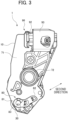
- Fig. 3 is a view of the developing cartridge 1 as viewed from a side of a second outer surface 12 (described later).
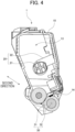
- Fig. 4 is a cross-sectional view of the developing cartridge 1. Note that Fig. 4 illustrates a cross-section orthogonal to the first direction.
- Fig. 5 is an exploded perspective view of the developing cartridge 1.
- the developing cartridge 1 is used with an electro-photographic type image forming apparatus.
- the image forming apparatus is a laser printer or an LED printer, for example.
- the developing cartridge 1 is attachable to and detachable from the drum cartridge including the photosensitive drum 100.
- the developing cartridge 1 is attached to the image forming apparatus while attached to the drum cartridge.
- the four developing cartridges 1 are attachable to the image forming apparatus, for example.
- the four developing cartridges 1 accommodate therein developer of colors different from one another (for example, the colors of cyan, magenta, yellow, and black).
- the developer is, for example, toner.
- the image forming apparatus forms images on printing sheets using developer supplied from the developing cartridges 1.
- the number of developing cartridges 1 that can be attached to the image forming apparatus may be one through three, or five or more.
- the developing cartridge 1 includes the casing 10, an agitator 20, the developing roller 30, a developing roller bearing 40, a first lever 50, a lever cover 60, a gear portion 70, a second lever 80, and a memory assembly 90.
- the casing 10 is a housing configured to accommodate therein developer.
- the casing 10 has the first outer surface 11, and the second outer surface 12.
- the first outer surface 11 is positioned at one end portion in the first direction of the casing 10.
- the second outer surface 12 is positioned at another end portion in the first direction of the casing 10.
- the first outer surface 11 and the second outer surface 12 are positioned away from each other in the first direction.
- the casing 10 extends in both the first direction and the second direction.
- the casing 10 has an accommodation chamber 13.
- the accommodation chamber 13 is positioned inside the casing 10. Developer is accommodated in the accommodation chamber 13.
- the casing 10 also has an opening 14.
- the opening 14 is positioned at the one end portion in the second direction of the casing 10.
- An outer space of the casing 10 and the accommodation chamber 13 are in communication with each other via the opening 14.
- the casing 10 may include a handle at an outer surface of the other end portion in the second direction of the casing 10.
- the casing 10 also has a filling port 15.
- the filling port 15 is positioned at the first outer surface 11. That is, the filling port 15 is positioned at the one end portion in the first direction of the casing 10.
- the casing 10 includes a cap 16.
- the cap 16 is mountable on and removable from the filling port 15. In a state where the cap 16 is mounted on the filling port 15, the cap 16 covers the filling port 15.
- the agitator 20 includes an agitator shaft 21, and a film 22.
- the agitator shaft 21 extends along the first direction.
- the film 22 expands toward an inner surface of the casing 10 from the agitator shaft 21. In other words, the film 22 expands radially outward from the agitator shaft 21.
- a part of the agitator shaft 21, and the film 22 are positioned inside the accommodation chamber 13 of the casing 10.
- One end portion in the first direction of the agitator shaft 21 is fixed to an agitator gear included in the gear portion 70.
- the agitator gear rotates, the agitator shaft 21 and the film 22 rotate about an agitator axis that extends in the first direction.
- the film 22 agitates the developer in the accommodation chamber 13.
- the developing roller 30 is a roller that is rotatable about a first axis extending in the first direction.
- the developing roller 30 is positioned at the opening 14 of the casing 10. In other words, the developing roller 30 is positioned at the one end portion in the second direction of the casing 10. When the developing cartridge 1 is attached to the drum cartridge, the developing roller 30 contacts the photosensitive drum 100.
- the developing roller 30 includes a developing roller body 31, and a developing roller shaft 32.
- the developing roller body 31 is a hollow cylindrical member that extends in the first direction. A rubber having elasticity is used as material of the developing roller body 31, for example.
- the developing roller shaft 32 is a solid cylindrical member that penetrates the developing roller body 31 to extend in the first direction.
- the developing roller body 31 is fixed to the developing roller shaft 32.
- the developing roller shaft 32 is electrically conductive.
- the developing roller shaft 32 is made of metal or electrically conductive resin.
- developing roller shaft 32 may not penetrate the developing roller body 31 in the first direction.
- developing roller shafts 32 may respectively extend in the first direction from both ends in the first direction of the developing roller body 31.
- the developing roller bearing 40 is positioned at the first outer surface 11 of the casing 10. That is, the developing roller bearing 40 is positioned at the one end portion in the first direction of the casing 10. More specifically, the developing roller bearing 40 is fixed to the first outer surface 11 of the casing 10.
- the developing roller bearing 40 is electrically conductive. Specifically, the developing roller bearing 40 is made of electrically conductive resin.
- the developing roller bearing 40 has a bearing hole 41.
- the bearing hole 41 penetrates the developing roller bearing 40 in the first direction.
- One end portion in the first direction of the developing roller shaft 32 is inserted through the bearing hole 41. Therefore, the developing roller shaft 32 is rotatably supported by the developing roller bearing 40. Further, the one end portion in the first direction of the developing roller shaft 32 contacts the developing roller bearing 40. As a result, the developing roller bearing 40 is electrically connected to the developing roller shaft 32.
- the image forming apparatus supplies a bias voltage to the developing roller shaft 32 via the developing roller bearing 40. Then, developer is carried on an outer circumferential surface of the developing roller body 31 due to an electrostatic force between the developing roller shaft 32 and the developer.
- the developing roller bearing 40 includes a bearing protrusion 42.
- the bearing protrusion 42 protrudes in the first direction from one end surface in the first direction of the developing roller bearing 40.
- the bearing protrusion 42 protrudes in a direction away from the casing 10 in the first direction.
- the bearing protrusion 42 is positioned between the developing roller shaft 32 and the first lever 50 in the second direction.
- the first lever 50 is positioned at the first outer surface 11 of the casing 10. In other words, the first lever 50 is positioned at the one end portion in the first direction of the casing 10. The first lever 50 is positioned away from the developing roller 30 in the second direction. As illustrated in Fig. 2 , the first lever 50 has one end portion 51 and another end portion 52, and includes a lever protrusion 53. The one end portion 51 and the other end portion 52 are positioned away from each other in a rotational direction about the lever protrusion 53. Also, the one end portion 51 is closer to the bearing protrusion 42 than the other end portion 52 is to the bearing protrusion 42. The lever protrusion 53 protrudes in the first direction from the first lever 50. The lever protrusion 53 extends in a direction away from the casing 10. The lever protrusion 53 is a hollow cylindrical or a solid cylindrical member centered on a second axis that extends in the first direction.
- the first lever 50 is movable relative to the casing 10. In a state where the developing cartridge 1 is attached to the drum cartridge, the lever protrusion 53 can contact a frame of the drum cartridge.
- the first lever 50 is pivotally movable about the lever protrusion 53 between a first position and a second position. In other words, in a state where the developing cartridge 1 is attached to the drum cartridge, the first lever 50 is pivotally movable relative to the casing 10 about the second axis between the first position and the second position.
- the first outer surface 11 of the casing 10 has a casing contact surface 111.
- the casing contact surface 111 is positioned farther from the developing roller 30 than the one end portion 51 of the first lever 50 is from the developing roller 30 in the second direction.
- the casing contact surface 111 faces the one end portion 51 of the first lever 50 in the second direction.
- the lever cover 60 is positioned at the first outer surface 11 of the casing 10. In other words, the lever cover 60 is positioned at the one end portion in the first direction of the casing 10. More specifically, the lever cover 60 is fixed to the first outer surface 11 of the casing 10. The lever cover 60 covers a part of the first lever 50. In other words, a part of the first lever 50 is positioned between the first outer surface 11 of the casing 10 and the lever cover 60. The lever cover 60 holds the first lever 50 while the first lever 50 is movable relative to the casing 10.
- the other end portion 52 of the first lever 50 protrudes in a direction away from the casing 10 in the first direction.
- the lever cover 60 is positioned between the other end portion 52 and the lever protrusion 53 of the first lever 50. Both the other end portion 52 and the lever protrusion 53 of the first lever 50 can contact the lever cover 60. This configuration prevents the first lever 50 from being removed from the casing 10 and the lever cover 60.
- the lever cover 60 covers the filling port 15 and the cap 16.
- the lever cover 60 and the cap 16 face each other in the first direction. This arrangement prevents removal of the cap 16 from the casing 10.
- the lever cover 60 may cover the filling port 15 and the cap 16 entirely, or may cover only parts of the filling port 15 and the cap 16. In other words, the lever cover 60 need only cover at least a part of the filling port 15 and the cap 16.
- the gear portion 70 is positioned at the second outer surface 12 of the casing 10. In other words, the gear portion 70 is positioned at the other end portion in the first direction of the casing 10.
- the gear portion 70 includes a gear cover 71, a coupling 72, and a plurality of gears.
- the gear cover 71 constitutes the housing of the developing cartridge 1 in cooperation with the casing 10.
- the gear cover 71 is fixed to the second outer surface 12 of the casing 10.
- the gears include the agitator gear fixed to the agitator shaft 21, and a developing roller gear fixed to the developing roller shaft 32. At least a part of the gears is positioned between the second outer surface 12 and the gear cover 71.
- the coupling 72 is exposed through the gear cover 71.
- a drive shaft in the image forming apparatus is coupled to the coupling 72. Rotation of the drive shaft is then transmitted to the agitator gear and the developing roller gear via the coupling 72.
- the plurality of gears included in the gear portion 70 may transmit a rotational force through engagement of gear teeth or by friction.
- the second lever 80 is positioned at the second outer surface 12 of the casing 10.
- the second lever 80 is positioned at the other end portion in the first direction of the casing 10. More specifically, the second lever 80 is positioned at an outer surface of the gear cover 71.
- the second lever 80 has one end portion 81, and another end portion 82.
- the other end portion 82 is positioned farther from the developing roller shaft 32 than the one end portion 81 is from the developing roller shaft 32.
- the other end portion 82 is positioned farther from the one end portion in the second direction of the casing 10 than the one end portion 81 is from the one end portion in the second direction of the casing 10 in the second direction.
- the second lever 80 extends along the second outer surface 12 of the casing 10 between the one end portion 81 and the other end portion 82.
- the second lever 80 has a through-hole 83.
- the through-hole 83 penetrates the one end portion 81 of the second lever 80 in the first direction.
- the through-hole 83 has a hollow cylindrical inner circumferential surface. Another end portion in the first direction of the developing roller shaft 32 is inserted through the through-hole 83. Accordingly, the second lever 80 is pivotally movable about the developing roller shaft 32 relative to the casing 10. Specifically, the other end portion 82 of the second lever 80 is pivotally movable about the developing roller shaft 32 relative to the one end portion 81 of the second lever 80.
- the developing cartridge 1 After the developing cartridge 1, while attached to the drum cartridge, is attached to the image forming apparatus, the developing cartridge 1 can perform a separating operation using a driving force supplied from the image forming apparatus.
- the separating operation is an operation for temporarily separating the developing roller 30 from the photosensitive drum 100.
- the image forming apparatus presses the other end portion 52 of the first lever 50. Accordingly, the first lever 50 pivotally moves relative to the casing 10 about the lever protrusion 53. The first lever 50 pivotally moves from the first position to the second position. As a result, the one end portion 51 of the first lever 50 contacts the casing contact surface 111 of the casing 10. The one end portion 51 of the first lever 50 then presses the casing contact surface 111 of the casing 10 in a direction away from the photosensitive drum 100 in the second direction. Consequently, the casing 10 moves in a direction away from the photosensitive drum 100 in the second direction. As a result, the developing roller 30 moves from a contacting position (a position indicated by two-dotted chain lines in Fig. 2 ) in which the developing roller 30 contacts the photosensitive drum 100 to a separated position (a position indicated by a solid line in Fig. 2 ) in which the developing roller 30 is separated from the photosensitive drum 100.
- the image forming apparatus When performing the separating operation, the image forming apparatus also presses a cam of the drum cartridge. Accordingly, the cam contacts the one end portion 81 of the second lever 80, and presses the one end portion 81 of the second lever 80 in a direction away from the photosensitive drum 100 in the second direction. Therefore, the casing 10 moves in a direction away from the photosensitive drum 100 in the second direction. As a result, the developing roller 30 moves from the contacting position in which the developing roller 30 contacts the photosensitive drum 100 to the separated position in which the developing roller 30 is separated from the photosensitive drum 100.
- the memory assembly 90 is positioned at the second outer surface 12 of the casing 10. In other words, the memory assembly 90 is positioned at the other end portion in the first direction of the casing 10. More specifically, the memory assembly 90 is positioned at the outer surface of the gear cover 71.
- the memory assembly 90 has a memory 91 which is a storage medium, a holder 92 that holds the memory 91, and a holder cover 93.
- the memory 91 is an IC chip, for example.
- the memory 91 is positioned at an outer surface of the holder 92.
- the memory 91 can store therein various information related to the developing cartridge 1. Specifically, the memory 91 stores therein at least one of the cumulative number of sheets printed using the developing roller 30, the cumulative number of revolutions of the developing roller 30, and the cumulative amount of developer consumed. This information is information that represents the service life of the developing cartridge 1. The memory 91 may also store therein such information as a serial number of the developing cartridge 1, compatible models for the developing cartridge 1, and the like.
- the memory 91 has an electrical contact surface 911.
- the electrical contact surface 911 is made of metal which is electrically conductive material. When the drum cartridge to which the developing cartridge 1 is attached is attached to the image forming apparatus, the electrical contact surface 911 contacts a terminal in the image forming apparatus.
- the holder cover 93 is fixed to the outer surface of the gear cover 71.
- the holder 92 is positioned between the gear cover 71 and the holder cover 93.
- the holder 92 is held in a state in which the holder 92 is movable relative to the casing 10, the gear cover 71, and the holder cover 93.
- Recycling of the developing cartridge 1 is an operation performed for bringing the developing cartridge 1 into a reusable condition by inspecting the used developing cartridge 1, refilling the accommodation chamber 13 in the developing cartridge 1 with developer, and replacing parts in the developing cartridge 1 if necessary.
- Figs. 6 and 7 are perspective views of a jig 900 used when recycling the developing cartridge 1. As illustrated in Figs. 6 and 7 , the jig 900 has a bearing groove 901, and a lever hole 902.
- the bearing groove 901 is a groove in which the bearing protrusion 42 described above can be inserted.
- the bearing groove 901 When the jig 900 is in its posture for use, the bearing groove 901 is recessed in the second direction.
- the bearing groove 901 also extends in the first direction when the jig 900 is in the posture for use.
- the lever hole 902 is a hole in which the lever protrusion 53 described above can be inserted.
- the lever hole 902 penetrates the jig 900 in the first direction.
- the lever hole 902 may also be a recess that is recessed in the first direction when the jig 900 is in the posture for use.
- FIG. 8 is a flowchart illustrating the recycling process according to the first embodiment.
- Fig. 9 is a partial perspective view of the developing cartridge 1 in a state where the jig 900 is mounted thereon.
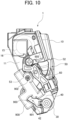
- Fig. 10 is a view of the developing cartridge 1 in a state where the jig 900 is mounted thereon as viewed from the side of the first outer surface 11.
- step A1 the bearing protrusion 42 of the developing roller bearing 40 is inserted into the bearing groove 901 of the jig 900.
- step A1 the lever protrusion 53 of the first lever 50 is inserted into the lever hole 902 of the jig 900.
- step A1 movement of the first lever 50 relative to the casing 10 is restricted. In other words, the first lever 50 is held on the casing 10 through the jig 900.
- the jig 900 includes a press-fitting protrusion 903.
- the press-fitting protrusion 903 protrudes toward an inside of the bearing groove 901 from an edge of the bearing groove 901.
- the press-fitting protrusion 903 contacts the bearing protrusion 42.
- the bearing protrusion 42 is press-fitted into the bearing groove 901.
- the jig 900 is fixed to the casing 10 and the developing roller bearing 40.
- step A1 the lever protrusion 53 is press-fitted into the lever hole 902. Therefore, the first lever 50 is fixed to the jig 900. Also, pivotal movement of the first lever 50 relative to the jig 900 about the lever protrusion 53 is restrained.
- the jig 900 also has a jig contact surface 904.
- the jig contact surface 904 faces the first lever 50 in a state where the jig 900 is mounted on both the casing 10 and the first lever 50. More specifically, the jig contact surface 904 faces a part of the first lever 50 in a pivot direction in which the first lever 50 pivotally moves about the lever protrusion 53.
- the first lever 50 pivotally moves about the lever protrusion 53 in a state where the jig 900 is mounted on both the casing 10 and the first lever 50, the first lever 50 contacts the jig contact surface 904 or the casing contact surface 111 of the casing 10. As a result, a range of the pivotal movement of the first lever 50 relative to the jig 900 is limited.
- step A2 a cover removing step. Specifically, the operator first removes a bolt fixing the lever cover 60 to the casing 10. Then the operator removes the lever cover 60 from the first outer surface 11 of the casing 10.
- Fig. 11 is a partial perspective view of the developing cartridge 1 in a state where the lever cover 60 is removed therefrom.
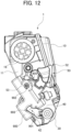
- Fig. 12 is a view of the developing cartridge 1 in a state where the lever cover 60 is removed therefrom as viewed from the side of the first outer surface 11.
- the cap 16 for the filling port 15 is exposed after the lever cover 60 is removed.
- the first lever 50 is held on the casing 10 through the jig 900. Therefore, the first lever 50 is held on the casing 10 though the lever cover 60 is removed. Accordingly, the operator can perform an operation of removing the lever cover 60 while the first lever 50 is held on the first outer surface 11 of the casing 10.
- step A3 a cap removing step. Accordingly, the filling port 15 is opened. At this time, the first lever 50 is held on the casing 10 through the jig 900. Therefore, the operator can perform an operation of removing the cap 16 while the first lever 50 is held on the first outer surface 11 of the casing 10.
- the operator inspects the removed cap 16. The operator prepares a new cap 16 if necessary.
- step A4 the operator sucks out developer remaining in the accommodation chamber 13 of the casing 10 (step A4, a sucking step). Specifically, the operator inserts a suction device into the filling port 15 and sucks developer in the accommodation chamber 13 into the suction device. As a result, the developer is removed from the accommodation chamber 13 of the casing 10. At this time, the first lever 50 is held on the casing 10 through the jig 900. Therefore, the operator can perform an operation to suck the developer while the first lever 50 is held on the first outer surface 11 of the casing 10.
- step A5 a filling step.
- the operator supplies developer into the accommodation chamber 13 in the casing 10 through the filling port 15.
- the first lever 50 is held on the casing 10 through the jig 900. Therefore, the operator can perform an operation to refill the casing 10 with developer while the first lever 50 is held on the first outer surface 11 of the casing 10.
- step A6 a cap mounting step. Accordingly, the filling port 15 is closed.
- the cap 16 mounted on the casing 10 may be the cap 16 removed in step A3, or may be a new cap 16.
- the developing cartridge 1 becomes a state illustrated in Figs. 11 and 12 .
- the first lever 50 is held on the casing 10 through the jig 900. Therefore, the operator can perform an operation of mounting the cap 16 while the first lever 50 is held on the first outer surface 11 of the casing 10.
- step A7 a cover mounting step
- the developing cartridge 1 becomes a state illustrated in Figs. 9 and 10 .
- the lever cover 60 mounted on the casing 10 may be the lever cover 60 removed in step A2, or may be a new lever cover 60.
- the operator fixes the lever cover 60 to the first outer surface 11 of the casing 10 with the bolt. Accordingly, the lever cover 60 covers the cap 16 mounted on the filling port 15. At this time, the first lever 50 is held on the casing 10 through the jig 900. Therefore, the operator can perform an operation of mounting the lever cover 60 while the first lever 50 is held on the first outer surface 11 of the casing 10.
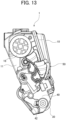
- Fig. 13 illustrates a movable range of the first lever 50 when the jig 900 is not mounted thereon.
- the lever cover 60 is omitted from Fig. 13
- the movable range of the first lever 50 is illustrated in Fig. 13 in a case where the lever cover 60 is mounted on the casing 10.
- the first lever 50 is movable relative to the casing 10, even when the lever cover 60 is mounted on the casing 10.
- the jig 900 can be used to limit such movement of the first lever 50.
- the position of the first lever 50 relative to the casing 10 when the lever cover 60 is mounted in step A7 does not change since the lever cover 60 has been removed in step A2. Therefore, the lever cover 60 can be mounted on the first outer surface 11 of the casing 10 without contacting the first lever 50.
- the jig 900 has a guide surface 905.
- the guide surface 905 In a state where the jig 900 is mounted on the casing 10 and the first lever 50, the guide surface 905 is positioned between the lever protrusion 53 and the other end portion 52 of the first lever 50. Further, in a state where the jig 900 is mounted on the casing 10 and the first lever 50, the guide surface 905 is inclined relative to the first direction. More specifically, in a state where the jig 900 is mounted on both the casing 10 and the first lever 50, the guide surface 905 approaches the other end portion 52 of the first lever 50 while approaching the casing 10 in the first direction.
- step A7 the operator moves the lever cover 60 toward the first outer surface 11 of the casing 10 while the lever cover 60 is in contact with the guide surface 905. Accordingly, the guide surface 905 guides the lever cover 60, thereby enabling the lever cover 60 to be easily positioned relative to the casing 10. In this way, the operation of mounting the lever cover 60 on the casing 10 can be performed easily.
- step A8 a jig removing step.
- the lever protrusion 53 of the first lever 50 is extracted from the lever hole 902 of the jig 900, and the bearing protrusion 42 of the developing roller bearing 40 is extracted from the bearing groove 901 in the jig 900.
- the jig 900 is removed from the casing 10 and the first lever 50.
- FIG. 14 is a flowchart illustrating the recycling process according to the second embodiment.
- the operator When performing recycling according to the second embodiment, the operator first removes the lever cover 60 from the casing 10 (step B 1, a cover removing step). Specifically, the operator first removes a bolt that fixes the lever cover 60 to the casing 10. The operator then removes the lever cover 60 from the first outer surface 11 of the casing 10. The cap 16 for the filling port 15 is exposed after the lever cover 60 is removed. Further, the first lever 50 is no longer held by the lever cover 60 once the lever cover 60 is removed.
- step B2 a lever removing step.
- the operator inspects the removed first lever 50.
- the operator prepares a new first lever 50 if necessary.
- step B3 the operator removes the cap 16 from the casing 10 (step B3, a cap removing step). Consequently, the filling port 15 is opened. The operator inspects the removed cap 16. The operator prepares a new cap 16 if necessary.
- step B4 the operator sucks out developer remaining in the accommodation chamber 13 of the casing 10 (step B4, a sucking step). Specifically, the operator inserts a suction device into the filling port 15 and sucks developer inside the accommodation chamber 13 into the suction device. As a result, the developer is removed from the accommodation chamber 13 of the casing 10.
- step B5 the operator fills the casing 10 with new developer. Specifically, the operator supplies developer into the accommodation chamber 13 of the casing 10 through the filling port 15.
- step B6 a cap mounting step. Accordingly, the filling port 15 is closed.
- the cap 16 mounted on the casing 10 may be the cap 16 removed in step B3, or may be a new cap 16.
- step B7 a lever mounting step
- the operator mounts the first lever 50 on the first outer surface 11 of the casing 10.
- the first lever 50 mounted on the first outer surface 11 of the casing 10 may be the first lever 50 removed in step B2, or may be a new first lever 50.
- step B8 a jig mounting step.
- the developing cartridge 1 becomes the state illustrated in Figs. 11 and 12 .
- step B8 the bearing protrusion 42 of the developing roller bearing 40 is inserted in the bearing groove 901 of the jig 900.
- step S8 the lever protrusion 53 of the first lever 50 is inserted in the lever hole 902 of the jig 900.
- the first lever 50 is mounted on the jig 900.
- movement of the first lever 50 relative to the casing 10 is restricted. In other words, the first lever 50 is held on the casing 10 through the jig 900.
- step B8 the press-fitting protrusion 903 contacts the bearing protrusion 42.
- the bearing protrusion 42 is press-fitted into the bearing groove 901.
- the jig 900 is fixed to the casing 10 and the developing roller bearing 40.
- the lever protrusion 53 is press-fitted into the lever hole 902 in step B8. Therefore, the first lever 50 is fixed to the jig 900. Also, the pivotal movement of the first lever 50 relative to the jig 900 about the lever protrusion 53 is restrained.
- the first lever 50 pivotally moves about the lever protrusion 53 while the jig 900 is mounted on both the casing 10 and the first lever 50, the first lever 50 contacts the jig contact surface 904 or the casing contact surface 111 of the casing 10. Accordingly, the range of the pivotal movement of the first lever 50 relative to the jig 900 is limited.
- step B9 a cover mounting step
- the developing cartridge 1 becomes the state illustrated in Figs. 9 and 10 .
- the lever cover 60 mounted on the casing 10 may be the lever cover 60 removed in step B1, or may be a new lever cover 60.
- the operator fixes the lever cover 60 to the first outer surface 11 of the casing 10 with the bolt. Therefore, the cap 16 mounted on the filling port 15 is covered by the lever cover 60. At this time, the first lever 50 is held on the casing 10 through the jig 900. Therefore, the operator can perform the operation for mounting the lever cover 60 while the first lever 50 is held on the first outer surface 11 of the casing 10.
- step B9 the operator moves the lever cover 60 toward the first outer surface 11 of the casing 10 while the lever cover 60 is in contact with the guide surface 905.
- the guide surface 905 guides the lever cover 60 so that the lever cover 60 can be easily positioned relative to the casing 10. Accordingly, the operation for mounting the lever cover 60 on the casing 10 can be performed easily.
- step B 10 a jig removing step.
- the lever protrusion 53 of the first lever 50 is extracted from the lever hole 902 in the jig 900.
- the bearing protrusion 42 of the developing roller bearing 40 is extracted from the bearing groove 901 in the jig 900.
- the jig 900 is removed from the casing 10 and the first lever 50.
- FIG. 15 is a flowchart illustrating the recycling process according to the third embodiment.
- the operator When performing recycling according to the third embodiment, the operator first removes the lever cover 60 from the casing 10 (step C1, a cover removing step). Specifically, the operator first removes a bolt that fixes the lever cover 60 to the casing 10. The operator then removes the lever cover 60 from the first outer surface 11 of the casing 10. The cap 16 for the filling port 15 is exposed after the lever cover 60 is removed. Further, the first lever 50 is no longer held by the lever cover 60 once the lever cover 60 is removed.
- step C2 a lever removing step.
- the operator inspects the removed first lever 50.
- the operator prepares a new first lever 50 if necessary.
- step C3 the operator removes the cap 16 from the casing 10 (step C3, a cap removing step). As a result, the filling port 15 is opened. The operator inspects the removed cap 16. The operator prepares a new cap 16 if necessary.
- step C4 the operator sucks out developer remaining in the accommodation chamber 13 of the casing 10 (step C4, a sucking step). Specifically, the operator inserts a suction device into the filling port 15 and sucks developer from the accommodation chamber 13 into the suction device. Therefore, the developer is removed from the accommodation chamber 13 of the casing 10.
- step C5 a memory assembly removing step. Specifically, the operator first removes a bolt that fixes the holder cover 93 to the gear cover 71. The operator then removes the holder cover 93 from the outer surface of the gear cover 71. Subsequently, the operator removes the holder 92 from the outer surface of the gear cover 71.
- the operator inspects the removed memory assembly 90.
- the operator overwrites information in the memory 91 as needed.
- the operator also replaces the memory 91 with a new memory 91 if necessary.
- the operator also prepares a new holder 92 or a new holder cover 93 if necessary.
- step C6 a second lever removing step. Specifically, the operator removes the second lever 80 from the other end portion in the first direction of the developing roller shaft 32. The operator inspects the removed second lever 80. The operator prepares a new second lever 80 if necessary.
- step C7 a gear portion removing step. Specifically, the operator first removes a bolt fixing the gear cover 71 to the casing 10. The operator then removes the gear cover 71 from the second outer surface 12 of the casing 10. Subsequently, the operator removes the coupling 72 and the plurality of gears from the second outer surface 12 of the casing 10.
- the operator inspects the removed gear cover 71, coupling 72, and gears. The operator prepares a new gear cover 71, a new coupling 72, or new gears if necessary.
- step C8 a developing roller bearing removing step. Specifically, the operator first removes a bolt that fixes the developing roller bearing 40 to the casing 10. The operator then removes the developing roller bearing 40 from the first outer surface 11 of the casing 10. The operator inspects the removed developing roller bearing 40. The operator prepares a new developing roller bearing 40 if necessary.
- step C9 a developing roller removing step. Specifically, the operator removes the developing roller 30 from the opening 14 in the casing 10. The operator inspects the removed developing roller 30. The operator prepares a new developing roller 30 if necessary.
- step C10 a developing roller mounting step
- the operator mounts the developing roller 30 on the opening 14 in the casing 10.
- the developing roller 30 mounted on the opening 14 in the casing 10 may be the developing roller 30 removed in step C9, or may be a new developing roller 30.
- step C11 a developing roller bearing mounting step. Specifically, the operator fixes the developing roller bearing 40 to the first outer surface 11 of the casing 10 using the bolt.
- the developing roller bearing 40 mounted on the first outer surface 11 of the casing 10 may be the developing roller bearing 40 removed in step C8, or may be a new developing roller bearing 40.
- step C12 a gear portion mounting step
- the operator first mounts the plurality of gears and the coupling 72 on the second outer surface 12 of the casing 10.
- step C12 a gear portion mounting step
- the operator mounts the gear cover 71 on the second outer surface 12 of the casing 10. Subsequently, the operator fixes the gear cover 71 to the casing 10 using the bolt.
- the gears, the coupling 72, and the gear cover 71 mounted on the second outer surface 12 of the casing 10 may be the gears, the coupling 72, and the gear cover 71 removed in step C7, or may be new gears, a new coupling 72, and a new gear cover 71.
- step C13 a second lever mounting step
- the operator mounts the second lever 80 on the casing 10 (step C13, a second lever mounting step).
- the operator mounts the second lever 80 on the outer surface of the gear cover 71.
- the operator then mounts the second lever 80 on the other end portion in the first direction of the developing roller shaft 32.
- the second lever 80 mounted on the developing roller shaft 32 may be the second lever 80 removed in step C6, or may be a new second lever 80.
- step C14 a memory assembly mounting step. Specifically, the operator mounts the holder 92 on the outer surface of the gear cover 71. The operator also mounts the holder cover 93 on the outer surface of the gear cover 71. The operator then fixes the holder cover 93 to the gear cover 71 with the bolt.
- the memory 91, the holder 92, and the holder cover 93 mounted on the outer surface of the gear cover 71 may be the memory 91, the holder 92, and the holder cover 93 removed in step C5, or may be a new memory 91, a new holder 92, and a new holder cover 93.
- step C15 a filling step. Specifically, the operator supplies developer into the accommodation chamber 13 of the casing 10 through the filling port 15.
- step C16 a cap mounting step. Therefore, the filling port 15 is closed.
- the cap 16 mounted on the casing 10 may be the cap 16 removed in step C3, or may be a new cap 16.
- step C17 a lever mounting step
- the operator mounts the first lever 50 on the first outer surface 11 of the casing 10.
- the first lever 50 mounted on the first outer surface 11 of the casing 10 may be the first lever 50 removed in step C2, or may be a new first lever 50.
- step C18 the operator mounts the jig 900 on the casing 10 and the first lever 50 (step C18, a jig mounting step).
- step C18 a jig mounting step.
- step C18 the bearing protrusion 42 of the developing roller bearing 40 is inserted in the bearing groove 901 of the jig 900.
- the jig 900 is mounted on the casing 10 and the developing roller bearing 40.
- step C18 the lever protrusion 53 of the first lever 50 is inserted in the lever hole 902 of the jig 900. Consequently, the first lever 50 is mounted on the jig 900.
- movement of the first lever 50 relative to the casing 10 is restricted. In other words, the first lever 50 is held on the casing 10 through the jig 900.
- step C18 the press-fitting protrusion 903 contacts the bearing protrusion 42. Accordingly, the bearing protrusion 42 is press-fitted into the bearing groove 901. As a result, the jig 900 is fixed relative to the casing 10 and the developing roller bearing 40. Also, in step C18, the lever protrusion 53 is press-fitted into the lever hole 902. Therefore, the first lever 50 is fixed relative to the jig 900. Further, the pivotal movement of the first lever 50 relative to the jig 900 about the lever protrusion 53 is restrained.
- the first lever 50 pivotally moves about the lever protrusion 53 in a state where the jig 900 is mounted on both the casing 10 and the first lever 50, the first lever 50 contacts the jig contact surface 904 or the casing contact surface 111 of the casing 10. In this way, the range of the pivotal movement of the first lever 50 relative to the jig 900 is limited.
- step C19 a cover mounting step
- the developing cartridge 1 becomes the state illustrated in Figs. 9 and 10 .
- the lever cover 60 mounted on the casing 10 may be the lever cover 60 removed in step C1, or may be a new lever cover 60.
- the operator fixes the lever cover 60 to the first outer surface 11 of the casing 10 with the bolt. Accordingly, the cap 16 mounted on the filling port 15 is covered by the lever cover 60. At this time, the first lever 50 is held on the casing 10 through the jig 900. Therefore, the operator can perform the operation of mounting the lever cover 60 while the first lever 50 is held on the first outer surface 11 of the casing 10.
- step C19 the operator moves the lever cover 60 toward the first outer surface 11 of the casing 10 while the lever cover 60 is in contact with the guide surface 905.
- the guide surface 905 guides the lever cover 60, thereby enabling the lever cover 60 to be easily positioned relative to the casing 10. Accordingly, the operation of mounting the lever cover 60 on the casing 10 can be performed simply.
- step C20 a jig removing step.
- the lever protrusion 53 of the first lever 50 is extracted from the lever hole 902 in the jig 900.
- the bearing protrusion 42 of the developing roller bearing 40 is extracted from the bearing groove 901 in the jig 900.
- the jig 900 is removed from the casing 10 and the first lever 50.
- the developing cartridge 1 may be attached to a drum cartridge including a single photosensitive drum, or to a drum cartridge including a plurality of photosensitive drums. Alternatively, the developing cartridge 1 may be attached to an image forming apparatus directly.
Landscapes
- Engineering & Computer Science (AREA)
- Physics & Mathematics (AREA)
- General Physics & Mathematics (AREA)
- Computer Vision & Pattern Recognition (AREA)
- Life Sciences & Earth Sciences (AREA)
- Sustainable Development (AREA)
- Manufacturing & Machinery (AREA)
- Dry Development In Electrophotography (AREA)
- Electrophotography Configuration And Component (AREA)
Abstract
Description
- The present disclosure relates to a recycling method of recycling a developing cartridge.
- There has been conventionally known an electro-photographic type image forming apparatus such as a laser printer or an LED printer. With the image forming apparatus, developing cartridges are used. A conventional developing cartridge is described in
Patent Literature 1, for example. The developing cartridge inPatent Literature 1 includes a lever that is movable relative to a housing. - [Patent Literature 1]
Japanese Patent Application Publication No. 2021-117386 - The housing of the developing cartridge has a filling port for filling the housing with developer, and includes a cap that covers the filling port. When recycling the developing cartridge, the cap is first removed from the housing. Next, the developer remaining inside the housing is sucked out and the housing is filled with new developer. Subsequently, the cap is mounted on the housing.
- When the developing cartridge includes the lever that is movable relative to the housing, as in
Patent Literature 1, a lever cover is needed for holding the lever on the housing. Also, it is conceivable that the lever cover covers the cap in order to prevent the cap from being inadvertently removed from the housing. - In a case where the lever cover has a configuration for covering the cap, the lever cover must be removed when recycling the developing cartridge. However, the lever is no longer held on the housing when the lever cover is removed. Moreover, when remounting the lever cover on the housing, the lever cover needs to be mounted in a state where the lever is held on an outer surface of the housing.
- It is an object of the present disclosure to provide a recycling method of recycling a developing cartridge that enables a lever cover to be mounted on a housing while the lever is held on an outer surface of the housing.
- First disclosure of the present application is a recycling method of recycling a developing cartridge attachable to and detachable from a drum cartridge including a photosensitive drum, and characterized in that: the developing cartridge includes: a developing roller rotatable about a first axis extending in a first direction; a housing configured to accommodate developer therein, the housing having a filling port positioned at one end portion in the first direction of the housing; a lever positioned at the one end portion in the first direction of the housing, wherein, in a state where the developing cartridge is attached to the drum cartridge, the lever is pivotally movable relative to the housing about a second axis extending in the first direction between: a first position in which the lever causes the developing roller to contact the photosensitive drum; and a second position in which the lever causes the developing roller to separate from the photosensitive drum; and a lever cover positioned at the one end portion in the first direction of the housing, the lever cover covering a part of the lever and at least a part of the filling port; the recycling method includes: a jig mounting step of mounting a jig on both the housing and the lever to restrict movement of the lever relative to the housing; a cover removing step of removing the lever cover from the housing; a filling step of filling the housing with developer through the filling port after the cover removing step; a cover mounting step of mounting the lever cover on the housing after the filling step; and a jig removing step of removing the jig from the housing and the lever after the cover mounting step; and the jig mounting step is performed before the cover mounting step at the latest.
- Second disclosure of the present application is the recycling method according to first disclosure, and characterized in that the jig mounting step is performed before the cover removing step.
- Third disclosure of the present application is the recycling method according to first disclosure or second disclosure, and characterized in that: the housing further has: a developing roller bearing positioned at the one end portion in the first direction of the housing, the developing roller bearing supporting the developing roller so that the developing roller is rotatable; and in the jig mounting step, the jig is mounted on the developing roller bearing.
- Fourth disclosure of the present application is the recycling method according to third disclosure, and characterized in that: the developing roller bearing includes a bearing protrusion protruding in the first direction; the jig has a bearing groove into which the bearing protrusion can be inserted; and in the jig mounting step, the bearing protrusion is inserted into the bearing groove.
- ]Fifth disclosure of the present application is the recycling method according to fourth disclosure, and characterized in that: the lever includes a lever protrusion protruding in the first direction; the jig has a lever hole into which the lever protrusion can be inserted; and in the jig mounting step, the lever protrusion is inserted into the lever hole.
- Sixth disclosure of the present application is the recycling method according to fifth disclosure, and characterized in that, in the jig mounting step, the lever protrusion is press-fitted into the lever hole.
- Seventh disclosure of the present application is the recycling method according to any one of first disclosure to sixth disclosure, and characterized in that the housing has a casing contacting surface configured to contact the lever in a state where the jig is mounted on both the housing and the lever.
- Eighth disclosure of the present application is the recycling method according to any one of first disclosure to seventh disclosure, and characterized in that the jig has a jig contacting surface configured to contact the lever in a state where the jig is mounted on both the housing and the lever.
- Ninth disclosure of the present application is the recycling method according to any one of first disclosure to eighth disclosure, and characterized in that the jig has a guide surface that guides the lever cover while the lever cover is being mounted on the housing in the cover mounting step.
- Tenth disclosure of the present application is the recycling method according to first disclosure, and characterized in that: the recycling method further includes: a lever removing step of removing the lever from the housing after the cover removing step and before the filling step; and a lever mounting step of mounting the lever on the housing after the filling step and before the cover mounting step; and the jig mounting step is performed after the lever mounting step and before the cover mounting step.
- Eleventh disclosure of the present application is the recycling method according to first disclosure to tenth disclosure, and characterized in that: the housing further has a cap that covers the filling port; and the recycling method further includes: a cap removing step of removing the cap from the housing after the cover removing step and before the filling step; and a cap mounting step of mounting the cap on the housing after the filling step and before the cover mounting step.
- According to first disclosure to eleventh disclosure of the present application, the lever cover is mounted on the housing in a state where the lever is held on the housing through the jig. Accordingly, the lever cover can be mounted on the housing while the lever is held on the one end portion in the first direction of the housing.
- Further, according to second disclosure of the present application, the lever cover can be removed from the housing in a state where the lever is held on the housing through the jig.
- Further, according to sixth disclosure of the present application, the lever can be restrained from pivotally moving relative to the jig.
- Further, according to seventh disclosure of the present application, the lever can be restrained from pivotally moving relative to the jig.
- Further, according to eighth disclosure of the present application, the lever can be restrained from pivotally moving relative to the jig.
- Further, according to ninth disclosure of the present application, the lever cover can be positioned relative to the housing easily by making use of the guide surface of the jig.
-
- [
Fig. 1] Fig. 1 is a perspective view of a developing cartridge. - [
Fig. 2] Fig. 2 is a view of the developing cartridge as viewed from a side of a first outer surface. - [
Fig. 3] Fig. 3 is a view of the developing cartridge as viewed from a side of a second outer surface. - [
Fig. 4] Fig. 4 is a cross-sectional view of the developing cartridge. - [
Fig. 5] Fig. 5 is an exploded perspective view of the developing cartridge. - [
Fig. 6] Fig. 6 is a perspective view of a jig. - [
Fig. 7] Fig. 7 is a perspective view of the jig. - [
Fig. 8] Fig. 8 is a flowchart illustrating a recycling process according to a first embodiment. - [
Fig. 9] Fig. 9 is a partial perspective view of the developing cartridge in a state where the jig is mounted thereon. - [
Fig. 10] Fig. 10 is a view of the developing cartridge in a state where the jig is mounted thereon as viewed from the side of the first outer surface. - [
Fig. 11] Fig. 11 is a partial perspective view of the developing cartridge in a state where a lever cover is removed therefrom. - [
Fig. 12] Fig. 12 is a view of the developing cartridge in a state where the lever cover is removed therefrom as viewed from the side of the first outer surface. - [
Fig. 13] Fig. 13 is a view illustrating a movable range of a first lever when the jig is not mounted thereon. - [
Fig. 14] Fig. 14 is a flowchart illustrating a recycling process according to a second embodiment. - [
Fig. 15] Fig. 15 is a flowchart illustrating a recycling process according to a third embodiment. - Hereinafter, embodiments of the present disclosure will be described while referring to the accompanying drawings.
- In the following description, a direction in which a developing
roller 30 extends will be referred to as "first direction." Further, a direction in which one end portion of acasing 10 at which the developingroller 30 is positioned and another end portion of thecasing 10 are arranged will be referred to as "second direction." The first direction and the second direction cross each other. Preferably, the first direction and the second direction are orthogonal to each other. -
Fig. 1 is a perspective view of a developingcartridge 1.Fig. 2 is a view of the developingcartridge 1 as viewed from a side of a first outer surface 11 (described later). Note that aphotosensitive drum 100 of a drum cartridge is also illustrated inFig. 2 .Fig. 3 is a view of the developingcartridge 1 as viewed from a side of a second outer surface 12 (described later).Fig. 4 is a cross-sectional view of the developingcartridge 1. Note thatFig. 4 illustrates a cross-section orthogonal to the first direction.Fig. 5 is an exploded perspective view of the developingcartridge 1. - The developing
cartridge 1 is used with an electro-photographic type image forming apparatus. The image forming apparatus is a laser printer or an LED printer, for example. - The developing
cartridge 1 is attachable to and detachable from the drum cartridge including thephotosensitive drum 100. The developingcartridge 1 is attached to the image forming apparatus while attached to the drum cartridge. - Four developing
cartridges 1 are attachable to the image forming apparatus, for example. The four developingcartridges 1 accommodate therein developer of colors different from one another (for example, the colors of cyan, magenta, yellow, and black). The developer is, for example, toner. The image forming apparatus forms images on printing sheets using developer supplied from the developingcartridges 1. However, the number of developingcartridges 1 that can be attached to the image forming apparatus may be one through three, or five or more. - As illustrated in
Figs. 1 through 5 , the developingcartridge 1 includes thecasing 10, anagitator 20, the developingroller 30, a developingroller bearing 40, afirst lever 50, alever cover 60, agear portion 70, asecond lever 80, and amemory assembly 90. - The
casing 10 is a housing configured to accommodate therein developer. Thecasing 10 has the firstouter surface 11, and the secondouter surface 12. The firstouter surface 11 is positioned at one end portion in the first direction of thecasing 10. The secondouter surface 12 is positioned at another end portion in the first direction of thecasing 10. The firstouter surface 11 and the secondouter surface 12 are positioned away from each other in the first direction. Thecasing 10 extends in both the first direction and the second direction. - The
casing 10 has anaccommodation chamber 13. Theaccommodation chamber 13 is positioned inside thecasing 10. Developer is accommodated in theaccommodation chamber 13. Thecasing 10 also has anopening 14. Theopening 14 is positioned at the one end portion in the second direction of thecasing 10. An outer space of thecasing 10 and theaccommodation chamber 13 are in communication with each other via theopening 14. Note that thecasing 10 may include a handle at an outer surface of the other end portion in the second direction of thecasing 10. - The
casing 10 also has a fillingport 15. The fillingport 15 is positioned at the firstouter surface 11. That is, the fillingport 15 is positioned at the one end portion in the first direction of thecasing 10. Also, thecasing 10 includes acap 16. Thecap 16 is mountable on and removable from the fillingport 15. In a state where thecap 16 is mounted on the fillingport 15, thecap 16 covers the fillingport 15. - The
agitator 20 includes anagitator shaft 21, and afilm 22. Theagitator shaft 21 extends along the first direction. Thefilm 22 expands toward an inner surface of thecasing 10 from theagitator shaft 21. In other words, thefilm 22 expands radially outward from theagitator shaft 21. A part of theagitator shaft 21, and thefilm 22 are positioned inside theaccommodation chamber 13 of thecasing 10. - One end portion in the first direction of the
agitator shaft 21 is fixed to an agitator gear included in thegear portion 70. When the agitator gear rotates, theagitator shaft 21 and thefilm 22 rotate about an agitator axis that extends in the first direction. When rotating, thefilm 22 agitates the developer in theaccommodation chamber 13. - The developing
roller 30 is a roller that is rotatable about a first axis extending in the first direction. The developingroller 30 is positioned at theopening 14 of thecasing 10. In other words, the developingroller 30 is positioned at the one end portion in the second direction of thecasing 10. When the developingcartridge 1 is attached to the drum cartridge, the developingroller 30 contacts thephotosensitive drum 100. - The developing
roller 30 includes a developingroller body 31, and a developingroller shaft 32. The developingroller body 31 is a hollow cylindrical member that extends in the first direction. A rubber having elasticity is used as material of the developingroller body 31, for example. The developingroller shaft 32 is a solid cylindrical member that penetrates the developingroller body 31 to extend in the first direction. The developingroller body 31 is fixed to the developingroller shaft 32. The developingroller shaft 32 is electrically conductive. The developingroller shaft 32 is made of metal or electrically conductive resin. - Note that the developing
roller shaft 32 may not penetrate the developingroller body 31 in the first direction. For example, developingroller shafts 32 may respectively extend in the first direction from both ends in the first direction of the developingroller body 31. - The developing
roller bearing 40 is positioned at the firstouter surface 11 of thecasing 10. That is, the developingroller bearing 40 is positioned at the one end portion in the first direction of thecasing 10. More specifically, the developingroller bearing 40 is fixed to the firstouter surface 11 of thecasing 10. The developingroller bearing 40 is electrically conductive. Specifically, the developingroller bearing 40 is made of electrically conductive resin. - The developing
roller bearing 40 has abearing hole 41. The bearinghole 41 penetrates the developingroller bearing 40 in the first direction. One end portion in the first direction of the developingroller shaft 32 is inserted through the bearinghole 41. Therefore, the developingroller shaft 32 is rotatably supported by the developingroller bearing 40. Further, the one end portion in the first direction of the developingroller shaft 32 contacts the developingroller bearing 40. As a result, the developingroller bearing 40 is electrically connected to the developingroller shaft 32. - When the drum cartridge to which the developing
cartridge 1 is attached is attached to the image forming apparatus, the image forming apparatus supplies a bias voltage to the developingroller shaft 32 via the developingroller bearing 40. Then, developer is carried on an outer circumferential surface of the developingroller body 31 due to an electrostatic force between the developingroller shaft 32 and the developer. - As illustrated in
Fig. 2 , the developingroller bearing 40 includes a bearingprotrusion 42. The bearingprotrusion 42 protrudes in the first direction from one end surface in the first direction of the developingroller bearing 40. The bearingprotrusion 42 protrudes in a direction away from thecasing 10 in the first direction. The bearingprotrusion 42 is positioned between the developingroller shaft 32 and thefirst lever 50 in the second direction. - The
first lever 50 is positioned at the firstouter surface 11 of thecasing 10. In other words, thefirst lever 50 is positioned at the one end portion in the first direction of thecasing 10. Thefirst lever 50 is positioned away from the developingroller 30 in the second direction. As illustrated inFig. 2 , thefirst lever 50 has oneend portion 51 and anotherend portion 52, and includes alever protrusion 53. The oneend portion 51 and theother end portion 52 are positioned away from each other in a rotational direction about thelever protrusion 53. Also, the oneend portion 51 is closer to the bearingprotrusion 42 than theother end portion 52 is to the bearingprotrusion 42. Thelever protrusion 53 protrudes in the first direction from thefirst lever 50. Thelever protrusion 53 extends in a direction away from thecasing 10. Thelever protrusion 53 is a hollow cylindrical or a solid cylindrical member centered on a second axis that extends in the first direction. - The
first lever 50 is movable relative to thecasing 10. In a state where the developingcartridge 1 is attached to the drum cartridge, thelever protrusion 53 can contact a frame of the drum cartridge. Thefirst lever 50 is pivotally movable about thelever protrusion 53 between a first position and a second position. In other words, in a state where the developingcartridge 1 is attached to the drum cartridge, thefirst lever 50 is pivotally movable relative to thecasing 10 about the second axis between the first position and the second position. - The first
outer surface 11 of thecasing 10 has acasing contact surface 111. Thecasing contact surface 111 is positioned farther from the developingroller 30 than the oneend portion 51 of thefirst lever 50 is from the developingroller 30 in the second direction. Thecasing contact surface 111 faces the oneend portion 51 of thefirst lever 50 in the second direction. By thefirst lever 50 pivotally moving about thelever protrusion 53, the oneend portion 51 can contact thecasing contact surface 111. - The
lever cover 60 is positioned at the firstouter surface 11 of thecasing 10. In other words, thelever cover 60 is positioned at the one end portion in the first direction of thecasing 10. More specifically, thelever cover 60 is fixed to the firstouter surface 11 of thecasing 10. Thelever cover 60 covers a part of thefirst lever 50. In other words, a part of thefirst lever 50 is positioned between the firstouter surface 11 of thecasing 10 and thelever cover 60. Thelever cover 60 holds thefirst lever 50 while thefirst lever 50 is movable relative to thecasing 10. - However, the
other end portion 52 of thefirst lever 50 protrudes in a direction away from thecasing 10 in the first direction. Thelever cover 60 is positioned between theother end portion 52 and thelever protrusion 53 of thefirst lever 50. Both theother end portion 52 and thelever protrusion 53 of thefirst lever 50 can contact thelever cover 60. This configuration prevents thefirst lever 50 from being removed from thecasing 10 and thelever cover 60. - The
lever cover 60 covers the fillingport 15 and thecap 16. Thelever cover 60 and thecap 16 face each other in the first direction. This arrangement prevents removal of thecap 16 from thecasing 10. Thelever cover 60 may cover the fillingport 15 and thecap 16 entirely, or may cover only parts of the fillingport 15 and thecap 16. In other words, thelever cover 60 need only cover at least a part of the fillingport 15 and thecap 16. - The
gear portion 70 is positioned at the secondouter surface 12 of thecasing 10. In other words, thegear portion 70 is positioned at the other end portion in the first direction of thecasing 10. Thegear portion 70 includes agear cover 71, acoupling 72, and a plurality of gears. Thegear cover 71 constitutes the housing of the developingcartridge 1 in cooperation with thecasing 10. Thegear cover 71 is fixed to the secondouter surface 12 of thecasing 10. The gears include the agitator gear fixed to theagitator shaft 21, and a developing roller gear fixed to the developingroller shaft 32. At least a part of the gears is positioned between the secondouter surface 12 and thegear cover 71. - The
coupling 72 is exposed through thegear cover 71. When the developingcartridge 1 is attached to the image forming apparatus while the developingcartridge 1 is attached the drum cartridge, a drive shaft in the image forming apparatus is coupled to thecoupling 72. Rotation of the drive shaft is then transmitted to the agitator gear and the developing roller gear via thecoupling 72. The plurality of gears included in thegear portion 70 may transmit a rotational force through engagement of gear teeth or by friction. - The
second lever 80 is positioned at the secondouter surface 12 of thecasing 10. In other words, thesecond lever 80 is positioned at the other end portion in the first direction of thecasing 10. More specifically, thesecond lever 80 is positioned at an outer surface of thegear cover 71. As illustrated inFig. 3 , thesecond lever 80 has oneend portion 81, and anotherend portion 82. Theother end portion 82 is positioned farther from the developingroller shaft 32 than the oneend portion 81 is from the developingroller shaft 32. Also, theother end portion 82 is positioned farther from the one end portion in the second direction of thecasing 10 than the oneend portion 81 is from the one end portion in the second direction of thecasing 10 in the second direction. Thesecond lever 80 extends along the secondouter surface 12 of thecasing 10 between the oneend portion 81 and theother end portion 82. - The
second lever 80 has a through-hole 83. The through-hole 83 penetrates the oneend portion 81 of thesecond lever 80 in the first direction. The through-hole 83 has a hollow cylindrical inner circumferential surface. Another end portion in the first direction of the developingroller shaft 32 is inserted through the through-hole 83. Accordingly, thesecond lever 80 is pivotally movable about the developingroller shaft 32 relative to thecasing 10. Specifically, theother end portion 82 of thesecond lever 80 is pivotally movable about the developingroller shaft 32 relative to the oneend portion 81 of thesecond lever 80. - After the developing
cartridge 1, while attached to the drum cartridge, is attached to the image forming apparatus, the developingcartridge 1 can perform a separating operation using a driving force supplied from the image forming apparatus. The separating operation is an operation for temporarily separating the developingroller 30 from thephotosensitive drum 100. - When performing the separating operation, the image forming apparatus presses the
other end portion 52 of thefirst lever 50. Accordingly, thefirst lever 50 pivotally moves relative to thecasing 10 about thelever protrusion 53. Thefirst lever 50 pivotally moves from the first position to the second position. As a result, the oneend portion 51 of thefirst lever 50 contacts thecasing contact surface 111 of thecasing 10. The oneend portion 51 of thefirst lever 50 then presses thecasing contact surface 111 of thecasing 10 in a direction away from thephotosensitive drum 100 in the second direction. Consequently, thecasing 10 moves in a direction away from thephotosensitive drum 100 in the second direction. As a result, the developingroller 30 moves from a contacting position (a position indicated by two-dotted chain lines inFig. 2 ) in which the developingroller 30 contacts thephotosensitive drum 100 to a separated position (a position indicated by a solid line inFig. 2 ) in which the developingroller 30 is separated from thephotosensitive drum 100. - When performing the separating operation, the image forming apparatus also presses a cam of the drum cartridge. Accordingly, the cam contacts the one
end portion 81 of thesecond lever 80, and presses the oneend portion 81 of thesecond lever 80 in a direction away from thephotosensitive drum 100 in the second direction. Therefore, thecasing 10 moves in a direction away from thephotosensitive drum 100 in the second direction. As a result, the developingroller 30 moves from the contacting position in which the developingroller 30 contacts thephotosensitive drum 100 to the separated position in which the developingroller 30 is separated from thephotosensitive drum 100. - The
memory assembly 90 is positioned at the secondouter surface 12 of thecasing 10. In other words, thememory assembly 90 is positioned at the other end portion in the first direction of thecasing 10. More specifically, thememory assembly 90 is positioned at the outer surface of thegear cover 71. Thememory assembly 90 has amemory 91 which is a storage medium, aholder 92 that holds thememory 91, and aholder cover 93. Thememory 91 is an IC chip, for example. Thememory 91 is positioned at an outer surface of theholder 92. - The
memory 91 can store therein various information related to the developingcartridge 1. Specifically, thememory 91 stores therein at least one of the cumulative number of sheets printed using the developingroller 30, the cumulative number of revolutions of the developingroller 30, and the cumulative amount of developer consumed. This information is information that represents the service life of the developingcartridge 1. Thememory 91 may also store therein such information as a serial number of the developingcartridge 1, compatible models for the developingcartridge 1, and the like. - The
memory 91 has anelectrical contact surface 911. Theelectrical contact surface 911 is made of metal which is electrically conductive material. When the drum cartridge to which the developingcartridge 1 is attached is attached to the image forming apparatus, theelectrical contact surface 911 contacts a terminal in the image forming apparatus. - The
holder cover 93 is fixed to the outer surface of thegear cover 71. Theholder 92 is positioned between thegear cover 71 and theholder cover 93. Theholder 92 is held in a state in which theholder 92 is movable relative to thecasing 10, thegear cover 71, and theholder cover 93. - Next, a process performed when recycling the above developing
cartridge 1 will be described. Recycling of the developingcartridge 1 is an operation performed for bringing the developingcartridge 1 into a reusable condition by inspecting the used developingcartridge 1, refilling theaccommodation chamber 13 in the developingcartridge 1 with developer, and replacing parts in the developingcartridge 1 if necessary. -
Figs. 6 and7 are perspective views of ajig 900 used when recycling the developingcartridge 1. As illustrated inFigs. 6 and7 , thejig 900 has a bearinggroove 901, and alever hole 902. - The bearing
groove 901 is a groove in which the bearingprotrusion 42 described above can be inserted. When thejig 900 is in its posture for use, the bearinggroove 901 is recessed in the second direction. The bearinggroove 901 also extends in the first direction when thejig 900 is in the posture for use. Thelever hole 902 is a hole in which thelever protrusion 53 described above can be inserted. When thejig 900 is in the posture for use, thelever hole 902 penetrates thejig 900 in the first direction. However, thelever hole 902 may also be a recess that is recessed in the first direction when thejig 900 is in the posture for use. - First, a recycling process according to a first embodiment will be described.
Fig. 8 is a flowchart illustrating the recycling process according to the first embodiment. - When performing recycling according to the first embodiment, an operator first mounts the
jig 900 on both thecasing 10 and the first lever 50 (step A1, a jig mounting step).Fig. 9 is a partial perspective view of the developingcartridge 1 in a state where thejig 900 is mounted thereon.Fig. 10 is a view of the developingcartridge 1 in a state where thejig 900 is mounted thereon as viewed from the side of the firstouter surface 11. - As illustrated in
Figs. 9 and10 , in step A1, the bearingprotrusion 42 of the developingroller bearing 40 is inserted into the bearinggroove 901 of thejig 900. As a result, thejig 900 is mounted on both thecasing 10 and the developingroller bearing 40. Also, as illustrated inFigs. 9 and10 , in step A1, thelever protrusion 53 of thefirst lever 50 is inserted into thelever hole 902 of thejig 900. As a result, movement of thefirst lever 50 relative to thecasing 10 is restricted. In other words, thefirst lever 50 is held on thecasing 10 through thejig 900. - Also, the
jig 900 includes a press-fittingprotrusion 903. The press-fittingprotrusion 903 protrudes toward an inside of the bearinggroove 901 from an edge of the bearinggroove 901. As illustrated inFigs. 9 and10 , in step A1, the press-fittingprotrusion 903 contacts the bearingprotrusion 42. With this configuration, the bearingprotrusion 42 is press-fitted into the bearinggroove 901. As a result, thejig 900 is fixed to thecasing 10 and the developingroller bearing 40. - Also, in step A1, the
lever protrusion 53 is press-fitted into thelever hole 902. Therefore, thefirst lever 50 is fixed to thejig 900. Also, pivotal movement of thefirst lever 50 relative to thejig 900 about thelever protrusion 53 is restrained. - As illustrated in
Fig. 7 , thejig 900 also has ajig contact surface 904. Thejig contact surface 904 faces thefirst lever 50 in a state where thejig 900 is mounted on both thecasing 10 and thefirst lever 50. More specifically, thejig contact surface 904 faces a part of thefirst lever 50 in a pivot direction in which thefirst lever 50 pivotally moves about thelever protrusion 53. When thefirst lever 50 pivotally moves about thelever protrusion 53 in a state where thejig 900 is mounted on both thecasing 10 and thefirst lever 50, thefirst lever 50 contacts thejig contact surface 904 or thecasing contact surface 111 of thecasing 10. As a result, a range of the pivotal movement of thefirst lever 50 relative to thejig 900 is limited. - Next, the operator removes the
lever cover 60 from the casing 10 (step A2, a cover removing step). Specifically, the operator first removes a bolt fixing thelever cover 60 to thecasing 10. Then the operator removes thelever cover 60 from the firstouter surface 11 of thecasing 10.Fig. 11 is a partial perspective view of the developingcartridge 1 in a state where thelever cover 60 is removed therefrom.Fig. 12 is a view of the developingcartridge 1 in a state where thelever cover 60 is removed therefrom as viewed from the side of the firstouter surface 11. - As illustrated in
Figs. 11 and12 , thecap 16 for the fillingport 15 is exposed after thelever cover 60 is removed. At this time, thefirst lever 50 is held on thecasing 10 through thejig 900. Therefore, thefirst lever 50 is held on thecasing 10 though thelever cover 60 is removed. Accordingly, the operator can perform an operation of removing thelever cover 60 while thefirst lever 50 is held on the firstouter surface 11 of thecasing 10. - The operator inspects the removed
first lever 50. The operator prepares a newfirst lever 50 if necessary. - Next, the operator removes the
cap 16 from the casing 10 (step A3, a cap removing step). Accordingly, the fillingport 15 is opened. At this time, thefirst lever 50 is held on thecasing 10 through thejig 900. Therefore, the operator can perform an operation of removing thecap 16 while thefirst lever 50 is held on the firstouter surface 11 of thecasing 10. - The operator inspects the removed
cap 16. The operator prepares anew cap 16 if necessary. - Next, the operator sucks out developer remaining in the
accommodation chamber 13 of the casing 10 (step A4, a sucking step). Specifically, the operator inserts a suction device into the fillingport 15 and sucks developer in theaccommodation chamber 13 into the suction device. As a result, the developer is removed from theaccommodation chamber 13 of thecasing 10. At this time, thefirst lever 50 is held on thecasing 10 through thejig 900. Therefore, the operator can perform an operation to suck the developer while thefirst lever 50 is held on the firstouter surface 11 of thecasing 10. - Next, the operator fills the
casing 10 with new developer (step A5, a filling step). Specifically, the operator supplies developer into theaccommodation chamber 13 in thecasing 10 through the fillingport 15. At this time, thefirst lever 50 is held on thecasing 10 through thejig 900. Therefore, the operator can perform an operation to refill thecasing 10 with developer while thefirst lever 50 is held on the firstouter surface 11 of thecasing 10. - Next, the operator mounts the
cap 16 on the casing 10 (step A6, a cap mounting step). Accordingly, the fillingport 15 is closed. Here, thecap 16 mounted on thecasing 10 may be thecap 16 removed in step A3, or may be anew cap 16. - When the
cap 16 is mounted, the developingcartridge 1 becomes a state illustrated inFigs. 11 and12 . At this time, thefirst lever 50 is held on thecasing 10 through thejig 900. Therefore, the operator can perform an operation of mounting thecap 16 while thefirst lever 50 is held on the firstouter surface 11 of thecasing 10. - Next, the operator mounts the
lever cover 60 on the casing 10 (step A7, a cover mounting step). Through this step, the developingcartridge 1 becomes a state illustrated inFigs. 9 and10 . Here, thelever cover 60 mounted on thecasing 10 may be thelever cover 60 removed in step A2, or may be anew lever cover 60. - Specifically, the operator fixes the
lever cover 60 to the firstouter surface 11 of thecasing 10 with the bolt. Accordingly, thelever cover 60 covers thecap 16 mounted on the fillingport 15. At this time, thefirst lever 50 is held on thecasing 10 through thejig 900. Therefore, the operator can perform an operation of mounting thelever cover 60 while thefirst lever 50 is held on the firstouter surface 11 of thecasing 10. -
Fig. 13 illustrates a movable range of thefirst lever 50 when thejig 900 is not mounted thereon. Although thelever cover 60 is omitted fromFig. 13 , the movable range of thefirst lever 50 is illustrated inFig. 13 in a case where thelever cover 60 is mounted on thecasing 10. When thejig 900 is not mounted, as illustrated inFig. 13 , thefirst lever 50 is movable relative to thecasing 10, even when thelever cover 60 is mounted on thecasing 10. - However, the
jig 900 can be used to limit such movement of thefirst lever 50. The position of thefirst lever 50 relative to thecasing 10 when thelever cover 60 is mounted in step A7 does not change since thelever cover 60 has been removed in step A2. Therefore, thelever cover 60 can be mounted on the firstouter surface 11 of thecasing 10 without contacting thefirst lever 50. - As illustrated in
Figs. 9 through 12 , thejig 900 has aguide surface 905. In a state where thejig 900 is mounted on thecasing 10 and thefirst lever 50, theguide surface 905 is positioned between thelever protrusion 53 and theother end portion 52 of thefirst lever 50. Further, in a state where thejig 900 is mounted on thecasing 10 and thefirst lever 50, theguide surface 905 is inclined relative to the first direction. More specifically, in a state where thejig 900 is mounted on both thecasing 10 and thefirst lever 50, theguide surface 905 approaches theother end portion 52 of thefirst lever 50 while approaching thecasing 10 in the first direction. - In step A7, the operator moves the
lever cover 60 toward the firstouter surface 11 of thecasing 10 while thelever cover 60 is in contact with theguide surface 905. Accordingly, theguide surface 905 guides thelever cover 60, thereby enabling thelever cover 60 to be easily positioned relative to thecasing 10. In this way, the operation of mounting thelever cover 60 on thecasing 10 can be performed easily. - Subsequently, the operator removes the
jig 900 from thecasing 10 and the first lever 50 (step A8, a jig removing step). Specifically, thelever protrusion 53 of thefirst lever 50 is extracted from thelever hole 902 of thejig 900, and the bearingprotrusion 42 of the developingroller bearing 40 is extracted from the bearinggroove 901 in thejig 900. As a result, thejig 900 is removed from thecasing 10 and thefirst lever 50. - Next, a recycling process according to a second embodiment will be described.
Fig. 14 is a flowchart illustrating the recycling process according to the second embodiment. - When performing recycling according to the second embodiment, the operator first removes the
lever cover 60 from the casing 10 (step B 1, a cover removing step). Specifically, the operator first removes a bolt that fixes thelever cover 60 to thecasing 10. The operator then removes thelever cover 60 from the firstouter surface 11 of thecasing 10. Thecap 16 for the fillingport 15 is exposed after thelever cover 60 is removed. Further, thefirst lever 50 is no longer held by thelever cover 60 once thelever cover 60 is removed. - The operator inspects the removed
lever cover 60. The operator prepares anew lever cover 60 if necessary. - Next, the operator removes the
first lever 50 from the casing 10 (step B2, a lever removing step). The operator inspects the removedfirst lever 50. The operator prepares a newfirst lever 50 if necessary. - Next, the operator removes the
cap 16 from the casing 10 (step B3, a cap removing step). Consequently, the fillingport 15 is opened. The operator inspects the removedcap 16. The operator prepares anew cap 16 if necessary. - Next, the operator sucks out developer remaining in the
accommodation chamber 13 of the casing 10 (step B4, a sucking step). Specifically, the operator inserts a suction device into the fillingport 15 and sucks developer inside theaccommodation chamber 13 into the suction device. As a result, the developer is removed from theaccommodation chamber 13 of thecasing 10. - Next, the operator fills the
casing 10 with new developer (step B5, a filling step). Specifically, the operator supplies developer into theaccommodation chamber 13 of thecasing 10 through the fillingport 15. - Next, the operator mounts the
cap 16 on the casing 10 (step B6, a cap mounting step). Accordingly, the fillingport 15 is closed. Here, thecap 16 mounted on thecasing 10 may be thecap 16 removed in step B3, or may be anew cap 16. - Next, the operator mounts the
first lever 50 on the casing 10 (step B7, a lever mounting step). Specifically, the operator mounts thefirst lever 50 on the firstouter surface 11 of thecasing 10. Here, thefirst lever 50 mounted on the firstouter surface 11 of thecasing 10 may be thefirst lever 50 removed in step B2, or may be a newfirst lever 50. - Next, the operator mounts the
jig 900 on thecasing 10 and the first lever 50 (step B8, a jig mounting step). As a result, the developingcartridge 1 becomes the state illustrated inFigs. 11 and12 . - As illustrated in
Figs. 11 and12 , in step B8, the bearingprotrusion 42 of the developingroller bearing 40 is inserted in the bearinggroove 901 of thejig 900. As a result, thejig 900 is mounted on thecasing 10 and the developingroller bearing 40. Also, as illustrated inFigs. 11 and12 , in step S8 thelever protrusion 53 of thefirst lever 50 is inserted in thelever hole 902 of thejig 900. Accordingly, thefirst lever 50 is mounted on thejig 900. As a result, movement of thefirst lever 50 relative to thecasing 10 is restricted. In other words, thefirst lever 50 is held on thecasing 10 through thejig 900. - As illustrated in
Figs. 11 and12 , in step B8, the press-fittingprotrusion 903 contacts the bearingprotrusion 42. With this configuration, the bearingprotrusion 42 is press-fitted into the bearinggroove 901. As a result, thejig 900 is fixed to thecasing 10 and the developingroller bearing 40. Further, in step S8, thelever protrusion 53 is press-fitted into thelever hole 902 in step B8. Therefore, thefirst lever 50 is fixed to thejig 900. Also, the pivotal movement of thefirst lever 50 relative to thejig 900 about thelever protrusion 53 is restrained. - Further, when the
first lever 50 pivotally moves about thelever protrusion 53 while thejig 900 is mounted on both thecasing 10 and thefirst lever 50, thefirst lever 50 contacts thejig contact surface 904 or thecasing contact surface 111 of thecasing 10. Accordingly, the range of the pivotal movement of thefirst lever 50 relative to thejig 900 is limited. - Next, the operator mounts the
lever cover 60 on the casing 10 (step B9, a cover mounting step). Through this step, the developingcartridge 1 becomes the state illustrated inFigs. 9 and10 . Here, thelever cover 60 mounted on thecasing 10 may be thelever cover 60 removed in step B1, or may be anew lever cover 60. - Specifically, the operator fixes the
lever cover 60 to the firstouter surface 11 of thecasing 10 with the bolt. Therefore, thecap 16 mounted on the fillingport 15 is covered by thelever cover 60. At this time, thefirst lever 50 is held on thecasing 10 through thejig 900. Therefore, the operator can perform the operation for mounting thelever cover 60 while thefirst lever 50 is held on the firstouter surface 11 of thecasing 10. - In step B9, the operator moves the
lever cover 60 toward the firstouter surface 11 of thecasing 10 while thelever cover 60 is in contact with theguide surface 905. In this way, theguide surface 905 guides thelever cover 60 so that thelever cover 60 can be easily positioned relative to thecasing 10. Accordingly, the operation for mounting thelever cover 60 on thecasing 10 can be performed easily. - Subsequently, the operator removes the
jig 900 from thecasing 10 and the first lever 50 (step B 10, a jig removing step). Specifically, thelever protrusion 53 of thefirst lever 50 is extracted from thelever hole 902 in thejig 900. Also, the bearingprotrusion 42 of the developingroller bearing 40 is extracted from the bearinggroove 901 in thejig 900. As a result, thejig 900 is removed from thecasing 10 and thefirst lever 50. - Next, a recycling process according to a third embodiment will be described.
Fig. 15 is a flowchart illustrating the recycling process according to the third embodiment. - When performing recycling according to the third embodiment, the operator first removes the
lever cover 60 from the casing 10 (step C1, a cover removing step). Specifically, the operator first removes a bolt that fixes thelever cover 60 to thecasing 10. The operator then removes thelever cover 60 from the firstouter surface 11 of thecasing 10. Thecap 16 for the fillingport 15 is exposed after thelever cover 60 is removed. Further, thefirst lever 50 is no longer held by thelever cover 60 once thelever cover 60 is removed. - The operator inspects the removed
lever cover 60. The operator prepares anew lever cover 60 if necessary. - Next, the operator removes the
first lever 50 from the casing 10 (step C2, a lever removing step). The operator inspects the removedfirst lever 50. The operator prepares a newfirst lever 50 if necessary. - Next, the operator removes the
cap 16 from the casing 10 (step C3, a cap removing step). As a result, the fillingport 15 is opened. The operator inspects the removedcap 16. The operator prepares anew cap 16 if necessary. - Next, the operator sucks out developer remaining in the
accommodation chamber 13 of the casing 10 (step C4, a sucking step). Specifically, the operator inserts a suction device into the fillingport 15 and sucks developer from theaccommodation chamber 13 into the suction device. Therefore, the developer is removed from theaccommodation chamber 13 of thecasing 10. - Next, the operator removes the
memory assembly 90 from the casing 10 (step C5, a memory assembly removing step). Specifically, the operator first removes a bolt that fixes theholder cover 93 to thegear cover 71. The operator then removes theholder cover 93 from the outer surface of thegear cover 71. Subsequently, the operator removes theholder 92 from the outer surface of thegear cover 71. - The operator inspects the removed
memory assembly 90. The operator overwrites information in thememory 91 as needed. The operator also replaces thememory 91 with anew memory 91 if necessary. The operator also prepares anew holder 92 or anew holder cover 93 if necessary. - Next, the operator removes the
second lever 80 from the casing 10 (step C6, a second lever removing step). Specifically, the operator removes thesecond lever 80 from the other end portion in the first direction of the developingroller shaft 32. The operator inspects the removedsecond lever 80. The operator prepares a newsecond lever 80 if necessary. - Next, the operator removes the
gear portion 70 from the casing 10 (step C7, a gear portion removing step). Specifically, the operator first removes a bolt fixing thegear cover 71 to thecasing 10. The operator then removes the gear cover 71 from the secondouter surface 12 of thecasing 10. Subsequently, the operator removes thecoupling 72 and the plurality of gears from the secondouter surface 12 of thecasing 10. - The operator inspects the removed
gear cover 71,coupling 72, and gears. The operator prepares anew gear cover 71, anew coupling 72, or new gears if necessary. - Next, the operator removes the developing
roller bearing 40 from the casing 10 (step C8, a developing roller bearing removing step). Specifically, the operator first removes a bolt that fixes the developingroller bearing 40 to thecasing 10. The operator then removes the developingroller bearing 40 from the firstouter surface 11 of thecasing 10. The operator inspects the removed developingroller bearing 40. The operator prepares a new developingroller bearing 40 if necessary. - Next, the operator removes the developing
roller 30 from the casing 10 (step C9, a developing roller removing step). Specifically, the operator removes the developingroller 30 from theopening 14 in thecasing 10. The operator inspects the removed developingroller 30. The operator prepares a new developingroller 30 if necessary. - Next, the operator mounts the developing
roller 30 on the casing 10 (step C10, a developing roller mounting step). Specifically, the operator mounts the developingroller 30 on theopening 14 in thecasing 10. Here, the developingroller 30 mounted on theopening 14 in thecasing 10 may be the developingroller 30 removed in step C9, or may be a new developingroller 30. - Next, the operator mounts the developing
roller bearing 40 on the casing 10 (step C11, a developing roller bearing mounting step). Specifically, the operator fixes the developingroller bearing 40 to the firstouter surface 11 of thecasing 10 using the bolt. Here, the developingroller bearing 40 mounted on the firstouter surface 11 of thecasing 10 may be the developingroller bearing 40 removed in step C8, or may be a new developingroller bearing 40. - Next, the operator mounts the
gear portion 70 on the casing 10 (step C12, a gear portion mounting step). Specifically, the operator first mounts the plurality of gears and thecoupling 72 on the secondouter surface 12 of thecasing 10. Next, the operator mounts thegear cover 71 on the secondouter surface 12 of thecasing 10. Subsequently, the operator fixes thegear cover 71 to thecasing 10 using the bolt. - Here, the gears, the
coupling 72, and thegear cover 71 mounted on the secondouter surface 12 of thecasing 10 may be the gears, thecoupling 72, and thegear cover 71 removed in step C7, or may be new gears, anew coupling 72, and anew gear cover 71. - Next, the operator mounts the
second lever 80 on the casing 10 (step C13, a second lever mounting step). Specifically, the operator mounts thesecond lever 80 on the outer surface of thegear cover 71. The operator then mounts thesecond lever 80 on the other end portion in the first direction of the developingroller shaft 32. Here, thesecond lever 80 mounted on the developingroller shaft 32 may be thesecond lever 80 removed in step C6, or may be a newsecond lever 80. - Next, the operator mounts the
memory assembly 90 on the casing 10 (step C14, a memory assembly mounting step). Specifically, the operator mounts theholder 92 on the outer surface of thegear cover 71. The operator also mounts theholder cover 93 on the outer surface of thegear cover 71. The operator then fixes theholder cover 93 to thegear cover 71 with the bolt. - Here, the
memory 91, theholder 92, and theholder cover 93 mounted on the outer surface of thegear cover 71 may be thememory 91, theholder 92, and theholder cover 93 removed in step C5, or may be anew memory 91, anew holder 92, and anew holder cover 93. - Next, the operator fills the
casing 10 with new developer (step C15, a filling step). Specifically, the operator supplies developer into theaccommodation chamber 13 of thecasing 10 through the fillingport 15. - Next, the operator mounts the
cap 16 on the casing 10 (step C16, a cap mounting step). Therefore, the fillingport 15 is closed. Here, thecap 16 mounted on thecasing 10 may be thecap 16 removed in step C3, or may be anew cap 16. - Next, the operator mounts the
first lever 50 on the casing 10 (step C17, a lever mounting step). Specifically, the operator mounts thefirst lever 50 on the firstouter surface 11 of thecasing 10. Here, thefirst lever 50 mounted on the firstouter surface 11 of thecasing 10 may be thefirst lever 50 removed in step C2, or may be a newfirst lever 50. - Next, the operator mounts the
jig 900 on thecasing 10 and the first lever 50 (step C18, a jig mounting step). As a result, the developingcartridge 1 becomes the state illustrated inFigs. 11 and12 . - As illustrated in
Figs. 11 and12 , in step C18, the bearingprotrusion 42 of the developingroller bearing 40 is inserted in the bearinggroove 901 of thejig 900. As a result, thejig 900 is mounted on thecasing 10 and the developingroller bearing 40. Further, as illustrated inFigs. 11 and12 , in step C18, thelever protrusion 53 of thefirst lever 50 is inserted in thelever hole 902 of thejig 900. Consequently, thefirst lever 50 is mounted on thejig 900. As a result, movement of thefirst lever 50 relative to thecasing 10 is restricted. In other words, thefirst lever 50 is held on thecasing 10 through thejig 900. - As illustrated in
Figs. 11 and12 , in step C18, the press-fittingprotrusion 903 contacts the bearingprotrusion 42. Accordingly, the bearingprotrusion 42 is press-fitted into the bearinggroove 901. As a result, thejig 900 is fixed relative to thecasing 10 and the developingroller bearing 40. Also, in step C18, thelever protrusion 53 is press-fitted into thelever hole 902. Therefore, thefirst lever 50 is fixed relative to thejig 900. Further, the pivotal movement of thefirst lever 50 relative to thejig 900 about thelever protrusion 53 is restrained. - Further, when the
first lever 50 pivotally moves about thelever protrusion 53 in a state where thejig 900 is mounted on both thecasing 10 and thefirst lever 50, thefirst lever 50 contacts thejig contact surface 904 or thecasing contact surface 111 of thecasing 10. In this way, the range of the pivotal movement of thefirst lever 50 relative to thejig 900 is limited. - Next, the operator mounts the
lever cover 60 on the casing 10 (step C19, a cover mounting step). Through this step, the developingcartridge 1 becomes the state illustrated inFigs. 9 and10 . Here, thelever cover 60 mounted on thecasing 10 may be thelever cover 60 removed in step C1, or may be anew lever cover 60. - Specifically, the operator fixes the
lever cover 60 to the firstouter surface 11 of thecasing 10 with the bolt. Accordingly, thecap 16 mounted on the fillingport 15 is covered by thelever cover 60. At this time, thefirst lever 50 is held on thecasing 10 through thejig 900. Therefore, the operator can perform the operation of mounting thelever cover 60 while thefirst lever 50 is held on the firstouter surface 11 of thecasing 10. - In step C19, the operator moves the
lever cover 60 toward the firstouter surface 11 of thecasing 10 while thelever cover 60 is in contact with theguide surface 905. In this way, theguide surface 905 guides thelever cover 60, thereby enabling thelever cover 60 to be easily positioned relative to thecasing 10. Accordingly, the operation of mounting thelever cover 60 on thecasing 10 can be performed simply. - Subsequently, the operator removes the
jig 900 from thecasing 10 and the first lever 50 (step C20, a jig removing step). Specifically, thelever protrusion 53 of thefirst lever 50 is extracted from thelever hole 902 in thejig 900. Also, the bearingprotrusion 42 of the developingroller bearing 40 is extracted from the bearinggroove 901 in thejig 900. As a result, thejig 900 is removed from thecasing 10 and thefirst lever 50. - The developing
cartridge 1 may be attached to a drum cartridge including a single photosensitive drum, or to a drum cartridge including a plurality of photosensitive drums. Alternatively, the developingcartridge 1 may be attached to an image forming apparatus directly. - 1: developing cartridge 10: casing 16: cap 20: agitator 30: developing roller 40: developing roller bearing 42: bearing protrusion 50: first lever 53: lever protrusion 60: lever cover 70: gear portion 80: second lever 90: memory assembly 100: photosensitive drum 111: casing contact surface 900: jig 901: bearing groove 902: lever hole 903: press-fitting protrusion 904: jig contact surface 905: guide surface
Claims (11)
- A recycling method of recycling a developing cartridge attachable to and detachable from a drum cartridge comprising a photosensitive drum,the developing cartridge comprising:a developing roller rotatable about a first axis extending in a first direction;a housing configured to accommodate developer therein, the housing having a filling port positioned at one end portion in the first direction of the housing;a lever positioned at the one end portion in the first direction of the housing, wherein, in a state where the developing cartridge is attached to the drum cartridge, the lever is pivotally movable relative to the housing about a second axis extending in the first direction between:a first position in which the lever causes the developing roller to contact the photosensitive drum; anda second position in which the lever causes the developing roller to separate from the photosensitive drum; anda lever cover positioned at the one end portion in the first direction of the housing, the lever cover covering a part of the lever and at least a part of the filling port,the recycling method comprising:a jig mounting step of mounting a jig on both the housing and the lever to restrict movement of the lever relative to the housing;a cover removing step of removing the lever cover from the housing;a filling step of filling the housing with developer through the filling port after the cover removing step;a cover mounting step of mounting the lever cover on the housing after the filling step; anda jig removing step of removing the jig from the housing and the lever after the cover mounting step,wherein the jig mounting step is performed before the cover mounting step at the latest.
- The recycling method according to claim 1,
wherein the jig mounting step is performed before the cover removing step. - The recycling method according to claim 1 or 2,wherein the housing further has:
a developing roller bearing positioned at the one end portion in the first direction of the housing, the developing roller bearing supporting the developing roller so that the developing roller is rotatable, andwherein, in the jig mounting step, the jig is mounted on the developing roller bearing. - The recycling method according to claim 3,wherein the developing roller bearing includes:
a bearing protrusion protruding in the first direction,wherein the jig has:
a bearing groove into which the bearing protrusion can be inserted, andwherein, in the jig mounting step, the bearing protrusion is inserted into the bearing groove. - The recycling method according to claim 4,wherein the lever includes:
a lever protrusion protruding in the first direction,wherein the jig has:
a lever hole into which the lever protrusion can be inserted, andwherein, in the jig mounting step, the lever protrusion is inserted into the lever hole. - The recycling method according to claim 5,
wherein, in the jig mounting step, the lever protrusion is press-fitted into the lever hole. - The recycling method according to any one of claims 1 to 6,
wherein the housing has:
a casing contacting surface configured to contact the lever in a state where the jig is mounted on both the housing and the lever. - The recycling method according to any one of claims 1 to 7,
wherein the jig has:
a jig contacting surface configured to contact the lever in a state where the jig is mounted on both the housing and the lever. - The recycling method according to any one of claims 1 to 8,
wherein the jig has:
a guide surface that guides the lever cover while the lever cover is being mounted on the housing in the cover mounting step. - The recycling method according to claim 1, further comprising:a lever removing step of removing the lever from the housing after the cover removing step and before the filling step; anda lever mounting step of mounting the lever on the housing after the filling step and before the cover mounting step,wherein the jig mounting step is performed after the lever mounting step and before the cover mounting step.
- The recycling method according to any one of claims 1 to 10,wherein the housing further has a cap configured to cover the filling port,the recycling method further comprising:
a cap removing step of removing the cap from the housing after the cover removing step and before the filling step; and
a cap mounting step of mounting the cap on the housing after the filling step and before the cover mounting step.
Applications Claiming Priority (2)
| Application Number | Priority Date | Filing Date | Title |
|---|---|---|---|
| JP2022013017A JP7797894B2 (en) | 2022-01-31 | 2022-01-31 | How to recycle developer cartridges |
| PCT/JP2023/002042 WO2023145718A1 (en) | 2022-01-31 | 2023-01-24 | Method for recycling developer cartridge |
Publications (2)
| Publication Number | Publication Date |
|---|---|
| EP4474917A1 true EP4474917A1 (en) | 2024-12-11 |
| EP4474917A4 EP4474917A4 (en) | 2026-01-28 |
Family
ID=87472026
Family Applications (1)
| Application Number | Title | Priority Date | Filing Date |
|---|---|---|---|
| EP23746929.1A Pending EP4474917A4 (en) | 2022-01-31 | 2023-01-24 | Method for recycling developer cartridge |
Country Status (5)
| Country | Link |
|---|---|
| US (1) | US12487555B2 (en) |
| EP (1) | EP4474917A4 (en) |
| JP (1) | JP7797894B2 (en) |
| CN (1) | CN118613770A (en) |
| WO (1) | WO2023145718A1 (en) |
Family Cites Families (9)
| Publication number | Priority date | Publication date | Assignee | Title |
|---|---|---|---|---|
| US5852762A (en) * | 1993-01-12 | 1998-12-22 | Ricoh Company, Ltd. | Toner magazine and cleaner for an electrophotographic apparatus |
| US6246848B1 (en) * | 1996-09-11 | 2001-06-12 | Canon Kabushiki Kaisha | Toner Container cap, toner container, and process cartridge |
| JP4711221B2 (en) | 2005-05-26 | 2011-06-29 | 富士ゼロックス株式会社 | Development device |
| JP2008191401A (en) | 2007-02-05 | 2008-08-21 | Murata Mach Ltd | Toner cartridge |
| JP4433095B1 (en) * | 2009-07-22 | 2010-03-17 | 富士ゼロックス株式会社 | Image forming agent container, image forming apparatus, image forming agent container mounting method, image forming agent container removing method, image forming agent filling method, and image forming agent refilling method. |
| JP5861581B2 (en) | 2012-07-09 | 2016-02-16 | ブラザー工業株式会社 | Process cartridge and image forming apparatus |
| US10921731B2 (en) | 2019-03-26 | 2021-02-16 | Brother Kogyo Kabushiki Kaisha | Developing cartridge |
| JP7369331B2 (en) | 2020-01-28 | 2023-10-26 | ブラザー工業株式会社 | developer cartridge |
| US12153358B2 (en) * | 2022-06-10 | 2024-11-26 | Kyocera Document Solutions Inc. | Toner container and image forming apparatus |
-
2022
- 2022-01-31 JP JP2022013017A patent/JP7797894B2/en active Active
-
2023
- 2023-01-24 WO PCT/JP2023/002042 patent/WO2023145718A1/en not_active Ceased
- 2023-01-24 CN CN202380018966.5A patent/CN118613770A/en active Pending
- 2023-01-24 EP EP23746929.1A patent/EP4474917A4/en active Pending
-
2024
- 2024-07-26 US US18/786,202 patent/US12487555B2/en active Active
Also Published As
| Publication number | Publication date |
|---|---|
| WO2023145718A1 (en) | 2023-08-03 |
| US12487555B2 (en) | 2025-12-02 |
| EP4474917A4 (en) | 2026-01-28 |
| US20240385569A1 (en) | 2024-11-21 |
| JP7797894B2 (en) | 2026-01-14 |
| JP2023111252A (en) | 2023-08-10 |
| CN118613770A (en) | 2024-09-06 |
Similar Documents
| Publication | Publication Date | Title |
|---|---|---|
| JP7306009B2 (en) | developer cartridge | |
| JP7803327B2 (en) | Drum cartridges and developing cartridges | |
| US11754941B2 (en) | Developing cartridge | |
| US20240176280A1 (en) | Developing cartridge including electrically non-conductive collar covering end portion of developing-roller shaft | |
| JP7552309B2 (en) | Developing cartridge | |
| US12487555B2 (en) | Recycling method of recycling developing cartridge that includes cover mounting step, and jig mounting step performed before cover mounting step | |
| JP7563204B2 (en) | Developing cartridge | |
| US11137697B2 (en) | Developing cartridge having pivotable developing electrode | |
| JP2023002011A (en) | developer cartridge | |
| CN116710851B (en) | Developer cartridge assembly method | |
| CN223051644U (en) | Developing cartridge | |
| JP2021162816A (en) | Developing cartridge | |
| EP3738000B1 (en) | Drum cartridge and developing cartridge |
Legal Events
| Date | Code | Title | Description |
|---|---|---|---|
| STAA | Information on the status of an ep patent application or granted ep patent |
Free format text: STATUS: THE INTERNATIONAL PUBLICATION HAS BEEN MADE |
|
| PUAI | Public reference made under article 153(3) epc to a published international application that has entered the european phase |
Free format text: ORIGINAL CODE: 0009012 |
|
| STAA | Information on the status of an ep patent application or granted ep patent |
Free format text: STATUS: REQUEST FOR EXAMINATION WAS MADE |
|
| 17P | Request for examination filed |
Effective date: 20240802 |
|
| AK | Designated contracting states |
Kind code of ref document: A1 Designated state(s): AL AT BE BG CH CY CZ DE DK EE ES FI FR GB GR HR HU IE IS IT LI LT LU LV MC ME MK MT NL NO PL PT RO RS SE SI SK SM TR |
|
| P01 | Opt-out of the competence of the unified patent court (upc) registered |
Free format text: CASE NUMBER: APP_66867/2024 Effective date: 20241218 |
|
| DAV | Request for validation of the european patent (deleted) | ||
| DAX | Request for extension of the european patent (deleted) | ||
| A4 | Supplementary search report drawn up and despatched |
Effective date: 20260102 |
|
| RIC1 | Information provided on ipc code assigned before grant |
Ipc: G03G 21/18 20060101AFI20251219BHEP Ipc: G03G 15/08 20060101ALI20251219BHEP |
|
| GRAP | Despatch of communication of intention to grant a patent |
Free format text: ORIGINAL CODE: EPIDOSNIGR1 |
|
| STAA | Information on the status of an ep patent application or granted ep patent |
Free format text: STATUS: GRANT OF PATENT IS INTENDED |
|
| INTG | Intention to grant announced |
Effective date: 20260618 |
|
| RIN1 | Information on inventor provided before grant (corrected) |
Inventor name: IWASA, GO Inventor name: HATANO, SHUHEI |
|
| GRAS | Grant fee paid |
Free format text: ORIGINAL CODE: EPIDOSNIGR3 |