EP4474899A1 - Protector for surface-mount leds - Google Patents
Protector for surface-mount leds Download PDFInfo
- Publication number
- EP4474899A1 EP4474899A1 EP23177153.6A EP23177153A EP4474899A1 EP 4474899 A1 EP4474899 A1 EP 4474899A1 EP 23177153 A EP23177153 A EP 23177153A EP 4474899 A1 EP4474899 A1 EP 4474899A1
- Authority
- EP
- European Patent Office
- Prior art keywords
- protector
- circuit carrier
- leds
- cover portion
- light
- Prior art date
- Legal status (The legal status is an assumption and is not a legal conclusion. Google has not performed a legal analysis and makes no representation as to the accuracy of the status listed.)
- Pending
Links
Images




Classifications
-
- G—PHYSICS
- G03—PHOTOGRAPHY; CINEMATOGRAPHY; ANALOGOUS TECHNIQUES USING WAVES OTHER THAN OPTICAL WAVES; ELECTROGRAPHY; HOLOGRAPHY
- G03B—APPARATUS OR ARRANGEMENTS FOR TAKING PHOTOGRAPHS OR FOR PROJECTING OR VIEWING THEM; APPARATUS OR ARRANGEMENTS EMPLOYING ANALOGOUS TECHNIQUES USING WAVES OTHER THAN OPTICAL WAVES; ACCESSORIES THEREFOR
- G03B15/00—Special procedures for taking photographs; Apparatus therefor
- G03B15/02—Illuminating scene
- G03B15/03—Combinations of cameras with lighting apparatus; Flash units
- G03B15/05—Combinations of cameras with electronic flash apparatus; Electronic flash units
-
- H—ELECTRICITY
- H04—ELECTRIC COMMUNICATION TECHNIQUE
- H04N—PICTORIAL COMMUNICATION, e.g. TELEVISION
- H04N23/00—Cameras or camera modules comprising electronic image sensors; Control thereof
- H04N23/56—Cameras or camera modules comprising electronic image sensors; Control thereof provided with illuminating means
-
- H—ELECTRICITY
- H04—ELECTRIC COMMUNICATION TECHNIQUE
- H04N—PICTORIAL COMMUNICATION, e.g. TELEVISION
- H04N23/00—Cameras or camera modules comprising electronic image sensors; Control thereof
- H04N23/57—Mechanical or electrical details of cameras or camera modules specially adapted for being embedded in other devices
-
- G—PHYSICS
- G03—PHOTOGRAPHY; CINEMATOGRAPHY; ANALOGOUS TECHNIQUES USING WAVES OTHER THAN OPTICAL WAVES; ELECTROGRAPHY; HOLOGRAPHY
- G03B—APPARATUS OR ARRANGEMENTS FOR TAKING PHOTOGRAPHS OR FOR PROJECTING OR VIEWING THEM; APPARATUS OR ARRANGEMENTS EMPLOYING ANALOGOUS TECHNIQUES USING WAVES OTHER THAN OPTICAL WAVES; ACCESSORIES THEREFOR
- G03B2215/00—Special procedures for taking photographs; Apparatus therefor
- G03B2215/05—Combinations of cameras with electronic flash units
- G03B2215/0503—Built-in units
-
- G—PHYSICS
- G03—PHOTOGRAPHY; CINEMATOGRAPHY; ANALOGOUS TECHNIQUES USING WAVES OTHER THAN OPTICAL WAVES; ELECTROGRAPHY; HOLOGRAPHY
- G03B—APPARATUS OR ARRANGEMENTS FOR TAKING PHOTOGRAPHS OR FOR PROJECTING OR VIEWING THEM; APPARATUS OR ARRANGEMENTS EMPLOYING ANALOGOUS TECHNIQUES USING WAVES OTHER THAN OPTICAL WAVES; ACCESSORIES THEREFOR
- G03B2215/00—Special procedures for taking photographs; Apparatus therefor
- G03B2215/05—Combinations of cameras with electronic flash units
- G03B2215/0564—Combinations of cameras with electronic flash units characterised by the type of light source
- G03B2215/0567—Solid-state light source, e.g. LED, laser
-
- G—PHYSICS
- G03—PHOTOGRAPHY; CINEMATOGRAPHY; ANALOGOUS TECHNIQUES USING WAVES OTHER THAN OPTICAL WAVES; ELECTROGRAPHY; HOLOGRAPHY
- G03B—APPARATUS OR ARRANGEMENTS FOR TAKING PHOTOGRAPHS OR FOR PROJECTING OR VIEWING THEM; APPARATUS OR ARRANGEMENTS EMPLOYING ANALOGOUS TECHNIQUES USING WAVES OTHER THAN OPTICAL WAVES; ACCESSORIES THEREFOR
- G03B2217/00—Details of cameras or camera bodies; Accessories therefor
- G03B2217/002—Details of arrangement of components in or on camera body
Definitions
- the invention relates to a protector for protecting surface-mount light-emitting diodes against mechanical damage.
- LEDs Light-emitting diodes
- PCB printed circuit board
- a circuit carrier with the LEDs mounted has to be handled for placing it in and connecting it to the device of which it is to form a component.
- This handling of the circuit carrier bears the risk of damage to the LEDs, in particular, if assembly is challenging, for example due to tight space conditions.
- driver monitoring systems where a camera for monitoring the driver of a vehicle is mounted next to LEDs operating in the infrared section of the electromagnetic spectrum for providing illumination for the scene to be captured by the camera.
- the available space next to the camera is small, requiring rather precise and controlled movements during assembly; this implies a high risk of damage to the LEDs.
- CN 112379567 A discloses an optical imaging system, which in a housing includes a processing module, an image sensor, a signal module, a power module, and a light emitting module.
- Light from the light emitting module is collimated by a collimating lens, passes into a light guide as parallel light, and reaches a diverging lens, which turns the parallel light into divergent light to be emitted from the optical imaging system.
- the diverging lens is positioned in a portion of the housing.
- the protector according to the invention for one or more surface-mount light-emitting diodes includes a support portion and a cover portion.
- the support portion and the cover portion are separate components.
- the support portion is provided for mechanically connecting to a circuit carrier on which the light-emitting diodes are mounted.
- the cover portion is configured to be mechanically connected to and supported by the support portion.
- the cover portion has one or more openings for allowing radiation from the one or more light-emitting diodes to pass through the cover portion.
- the openings may in particular be simple through-holes. There is a respective opening for each light-emitting diode to be protected by the protector.
- the support portion and cover portion forming the protector when mounted on a circuit carrier, surround the light-emitting diodes on a number of sides; in particular, the cover portion restricts access along a direction perpendicular to a surface of the circuit carrier on which circuitry is laid out and surface-mount devices connected. Along this direction, the cover portion, or at least a part of the cover portion including the openings, is at a larger distance from this surface than any part of a light-emitting diode the protector is to protect.
- the protector also makes accidental access to the LEDs along directions parallel to this surface less likely. Therefore, by covering LEDs with a protector according to the invention the risk of mechanically damaging the LEDs is reduced.
- the support portion is configured to be connected to the circuit carrier by soldering or by a snap connection.
- the cover portion is configured to be connected to the support portion by a snap connection.
- a snap connection is easily established without requiring special equipment and may also be undone without special equipment should access to the LEDs be necessary at a later stage.
- the support portion includes a sidewall to be connected to the circuit carrier and a pass-through section connected to the sidewall, the pass-through section having an opening for the light-emitting diodes to protrude through.
- the support portion is connected to the circuit carrier by connecting its sidewall to the circuit carrier, for example, as stated above, by soldering or by a snap connection.
- a line where the sidewall connects to the circuit carrier can be of any shape compatible with the requirement that the protector is to protect the LEDs and therefore said line has to at least partially circumscribe an area within which the LEDs concerned are located.
- the line may form an open or closed polygon.
- the support portion is shaped out of one piece of sheet metal; the sidewall may be perpendicular to the pass-through section.
- the sheet metal may have a thickness of 0.2 mm.
- the cover portion may also be made of sheet metal. Using sheet metal as material has the additional advantage of providing increased heat extraction, compared with a protector made of plastic, for example.
- the support portion shaped according to this embodiment can be placed over the LEDs to be protected and the support portion can be mechanically connected to the circuit carrier.
- the LEDs protrude through the opening in the pass-through section.
- the cover portion is attached to the support portion; the cover portion covers the LEDs apart from the openings in the cover portion.
- the sidewall has plural sections, which sections are separated from each other but connected via the pass-through section.
- the sidewall may have precisely two, or precisely three, or precisely four sections.
- An assembly according to the invention includes a circuit carrier, one or more light-emitting diodes surface-mounted to the circuit carrier, and a protector according to the invention, as described above.
- the protector is mounted on the circuit carrier in such a way that each of the one or more light emitting diodes is aligned with one of the openings of the cover portion. This alignment assures that while the protector provides protection of the LEDs against mechanical damage, the light from the LEDs can still be emitted properly.
- the protector may be soldered to the circuit carrier or may be connected to the circuit carrier by a snap connection.
- the circuit carrier has to be configured accordingly.
- slots could be provided in the circuit carrier for snap connectors at the support portion of the protector to pass through and snap in.
- the assembly may include plural surface-mounted LEDs each of which is protected by a separate protector.
- the assembly may additionally or alternatively include plural LEDs which are protected by a common protector.
- the circuit carrier may be a printed circuit board (PCB).
- PCB printed circuit board
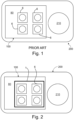
- Fig. 1 shows a camera module 200 including prior art assembly 100 and a camera 210.
- the assembly 100 includes a circuit carrier 80, which here is a printed circuit board, on which four LEDs 6 are surface-mounted.
- the circuit carrier 80 includes further electronic devices, which, however, are not relevant for the description of the invention and therefore are not shown.
- the LEDs 6 are mounted on a surface of the circuit carrier 80; there is no specific protection for the LEDs 6, which exposes the LEDs 6 to the risk of mechanical damage when assembly 100 is mounted into the camera module 200.
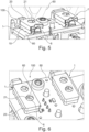
- Fig. 2 again shows a camera module 200, largely analogous to the camera module shown in Fig. 1 .
- the camera module 200 includes an assembly 100 according to the invention.
- a protector 1 connected to the circuit carrier 80 provides mechanical protection for the four LEDs 6 surface-mounted on the circuit carrier 80. This mechanical protection reduces the risk of mechanical damage when assembly 100 is mounted into the camera module 200.
- Fig. 3 shows an assembly 100 according to the invention.
- a circuit carrier 80 four LEDs 6 are surface-mounted. Shown are two protectors 1 according to the invention. Each protector 1 is provided to protect two of the LEDs 6.
- the protectors 1 are shown in an exploded view with respective cover portion 20 separated from corresponding support portion 10. Support portions 10 are connected to the circuit carrier 80.
- Each cover portion 20 has two openings 21, each opening 21 aligned with one of the LEDs 6.
- the assembly 100 here, and indeed in further figures herein, is part of a camera module of which camera 210 is shown.
- the invention is not restricted to camera modules.
- Fig. 4 is a top view of the assembly 100 according to the invention shown in Fig. 3 .
- Cover portions 20 of the protectors 1 are connected to the support portions 10 (not visible here, see Fig. 3 ). It can be clearly seen that each of the LEDs 6 mounted on the circuit carrier 80 is aligned with one of the openings 21 (see Fig. 3 ) of the cover portion 20.
- Fig. 5 is a sectional view of assembly 100 according to the invention shown in Fig. 3 . Shown are two protectors 1, each with support portion 10 connected to circuit carrier 80 and cover portion 20 connected to the support portion 10. Also shown is light 60 emitted from the LEDs 6 surface-mounted to the circuit carrier 80 and passing through openings 21 in cover portion 20. Each opening 21 is aligned with one of the LEDs 6. It should be appreciated here that the LEDs 6 do not protrude through the openings 21 but are entirely within the respective protector 1. This arrangement allows light 60 to be emitted from the assembly 100 while providing optimal mechanical protection for the LEDs 6.
- Fig. 6 is a further view of the assembly 100 according to the invention shown in Fig. 3 .
- the view shown here again clearly illustrates the alignment of the LEDs 6 mounted on the circuit carrier 80 with the openings 21 in the cover portions 20 of protectors 1. This allows light 60 to pass through the cover portion 20, while the LEDs 6 are mechanically protected, as, in the perspective shown, they are below the cover portion 20.
- Fig. 7 shows an assembly 100 according to the invention, with two different embodiments of protectors 1A, 1C.
- Each of the protectors 1A and 1C protects two LEDs 6 which are aligned with respective openings 21 in cover portion 20 of the respective protector 1A, 1C.
- the cover portion 20 is connected to a support portion 10 by a snap connection; the support portion 10 is mechanically connected to circuit carrier 80.
- Fig. 8 shows a protector 1A according to the invention.
- Support portion 10 supports cover portion 20, which is mounted to sidewall 11 of the support portion 10 by a snap connection.
- Cover portion 20 has two openings 21, to be aligned with LEDs on a circuit carrier, for light from these LEDs to exit from the protector 1A.
- Fig. 9 shows the protector 1A of Fig. 8 in an exploded view, with cover portion 20 detached from support portion 10.
- Support portion 10 has sidewall 11 and pass-through section 12, which is perpendicular to the sidewall 11.
- Pass-through section 12 has an opening 13 for LEDs on a circuit carrier to protrude through. Note that while the LEDs are intended to protrude through opening 13 of the pass-through section 12, the LEDs are intended not to protrude through openings 21 in the cover portion 20.
- the sidewall 11 has four sections 14; the four sections 14 are separate from each other but are connected via the pass-through section 12.
- the support portion 10 here is made from a single piece of sheet metal.
- the cover portion 20 here also is made from a single piece of sheet metal.
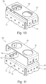
- Fig. 10 shows a protector 1B according to the invention.
- Support portion 10 supports cover portion 20, which is mounted to sidewall 11 of the support portion 10 by a snap connection.
- Cover portion 20 has two openings 21, to be aligned with LEDs on a circuit carrier, for light from these LEDs to exit from the protector 1B.
- Fig. 11 shows the protector 1B of Fig. 10 in an exploded view, with cover portion 20 detached from support portion 10.
- Support portion 10 has sidewall 11 and pass-through section 12, which is perpendicular to the sidewall 11.
- Pass-through section 12 has an opening 13 for LEDs on a circuit carrier to protrude through. Note that while the LEDs are intended to protrude through opening 13 of the pass-through section 12, the LEDs are intended not to protrude through openings 21 in the cover portion 20.
- the sidewall 11 has three sections 14; the three sections 14 are separate from each other but are connected via the pass-through section 12.
- the support portion 10 here is made from a single piece of sheet metal.
- the cover portion 20 here also is made from a single piece of sheet metal.
- Fig. 12 shows a protector 1C according to the invention.
- Support portion 10 supports cover portion 20, which is mounted to sidewall 11 of the support portion 10 by a snap connection.
- Cover portion 20 has two openings 21, to be aligned with LEDs on a circuit carrier, for light from these LEDs to exit from the protector 1C.
- Fig. 13 shows the protector 1C of Fig. 12 in an exploded view, with cover portion 20 detached from support portion 10.
- Support portion 10 has sidewall 11 and pass-through section 12, which is perpendicular to the sidewall 11.
- Pass-through section 12 has an opening 13 for LEDs on a circuit carrier to protrude through. Note that while the LEDs are intended to protrude through opening 13 of the pass-through section 12, the LEDs are intended not to protrude through openings 21 in the cover portion 20.
- the sidewall 11 has two sections 14; the two sections 14 are separate from each other but are connected via the pass-through section 12.
- the support portion 10 here is made from a single piece of sheet metal.
- the cover portion 20 here also is made from a single piece of sheet metal.
- Protector 1A having a sidewall 11 with four sections 14 provides a larger soldering area on the support portion 10 for connecting to a circuit carrier. Therefore, the protector 1A can be more firmly attached to the circuit carrier, ensuring more robustness against external forces.
- Protectors 1B and 1C require less material, and therefore are lighter and more cost effective.
- the sidewall 11 has only three or two, respectively, sections 14 instead of four, protectors 1B and 1C allow better access for automatic optical inspection of a circuit carrier with LEDs, protectors, and any further components mounted.
Landscapes
- Engineering & Computer Science (AREA)
- Multimedia (AREA)
- Signal Processing (AREA)
- Physics & Mathematics (AREA)
- General Physics & Mathematics (AREA)
- Led Device Packages (AREA)
Abstract
A protector (1) for surface-mounted LEDs (6) includes a support portion (10) to connect to a circuit carrier (80), e.g., a PCB, on which the LEDs (6) are mounted, and a cover portion (20) supported by and connected to the support portion (10). The cover portion (20) has one or more openings (21) for radiation from the LEDs (6) to pass through. The protector (1) is mounted on the circuit carrier (80) in such a way that the openings (21) of the cover portion (20) are aligned with the LEDs (6).
Description
- The invention relates to a protector for protecting surface-mount light-emitting diodes against mechanical damage.
- Light-emitting diodes (LEDs) in surface-mount technology are used in a wide variety of devices in diverse areas of technology. Such LEDs are mounted on a circuit carrier, often a printed circuit board (PCB). During assembly of a device, such a circuit carrier with the LEDs mounted has to be handled for placing it in and connecting it to the device of which it is to form a component. This handling of the circuit carrier bears the risk of damage to the LEDs, in particular, if assembly is challenging, for example due to tight space conditions. One specific use example is driver monitoring systems, where a camera for monitoring the driver of a vehicle is mounted next to LEDs operating in the infrared section of the electromagnetic spectrum for providing illumination for the scene to be captured by the camera. Here, often the available space next to the camera is small, requiring rather precise and controlled movements during assembly; this implies a high risk of damage to the LEDs.
-
CN 112379567 A discloses an optical imaging system, which in a housing includes a processing module, an image sensor, a signal module, a power module, and a light emitting module. Light from the light emitting module is collimated by a collimating lens, passes into a light guide as parallel light, and reaches a diverging lens, which turns the parallel light into divergent light to be emitted from the optical imaging system. The diverging lens is positioned in a portion of the housing. - It is an object of the invention to reduce the risk of mechanical damage to surface-mount LEDs during assembly.
- This object is achieved by a protector according to
claim 1. Claim 8 relates to a corresponding assembly. The dependent claims refer to advantageous embodiments. - The protector according to the invention for one or more surface-mount light-emitting diodes includes a support portion and a cover portion. The support portion and the cover portion are separate components. The support portion is provided for mechanically connecting to a circuit carrier on which the light-emitting diodes are mounted. The cover portion is configured to be mechanically connected to and supported by the support portion. The cover portion has one or more openings for allowing radiation from the one or more light-emitting diodes to pass through the cover portion. The openings may in particular be simple through-holes. There is a respective opening for each light-emitting diode to be protected by the protector. This assures that light from each such light-emitting diode can escape from the protector but does not open up the cover portion unnecessarily. The support portion and cover portion forming the protector, when mounted on a circuit carrier, surround the light-emitting diodes on a number of sides; in particular, the cover portion restricts access along a direction perpendicular to a surface of the circuit carrier on which circuitry is laid out and surface-mount devices connected. Along this direction, the cover portion, or at least a part of the cover portion including the openings, is at a larger distance from this surface than any part of a light-emitting diode the protector is to protect. The protector also makes accidental access to the LEDs along directions parallel to this surface less likely. Therefore, by covering LEDs with a protector according to the invention the risk of mechanically damaging the LEDs is reduced.
- In an embodiment the support portion is configured to be connected to the circuit carrier by soldering or by a snap connection.
- In an embodiment, the cover portion is configured to be connected to the support portion by a snap connection. A snap connection is easily established without requiring special equipment and may also be undone without special equipment should access to the LEDs be necessary at a later stage.
- In an embodiment, the support portion includes a sidewall to be connected to the circuit carrier and a pass-through section connected to the sidewall, the pass-through section having an opening for the light-emitting diodes to protrude through. Here the support portion is connected to the circuit carrier by connecting its sidewall to the circuit carrier, for example, as stated above, by soldering or by a snap connection. A line where the sidewall connects to the circuit carrier can be of any shape compatible with the requirement that the protector is to protect the LEDs and therefore said line has to at least partially circumscribe an area within which the LEDs concerned are located. For example, the line may form an open or closed polygon.
- In a more specific variant of this embodiment the support portion is shaped out of one piece of sheet metal; the sidewall may be perpendicular to the pass-through section.
- As a non-limiting example, the sheet metal may have a thickness of 0.2 mm. The cover portion may also be made of sheet metal. Using sheet metal as material has the additional advantage of providing increased heat extraction, compared with a protector made of plastic, for example.
- The support portion shaped according to this embodiment can be placed over the LEDs to be protected and the support portion can be mechanically connected to the circuit carrier. The LEDs protrude through the opening in the pass-through section. Subsequently, the cover portion is attached to the support portion; the cover portion covers the LEDs apart from the openings in the cover portion. In specific examples the sidewall has plural sections, which sections are separated from each other but connected via the pass-through section. For instance, and without being limited thereto, the sidewall may have precisely two, or precisely three, or precisely four sections.
- An assembly according to the invention includes a circuit carrier, one or more light-emitting diodes surface-mounted to the circuit carrier, and a protector according to the invention, as described above. The protector is mounted on the circuit carrier in such a way that each of the one or more light emitting diodes is aligned with one of the openings of the cover portion. This alignment assures that while the protector provides protection of the LEDs against mechanical damage, the light from the LEDs can still be emitted properly.
- For example, the protector may be soldered to the circuit carrier or may be connected to the circuit carrier by a snap connection. The circuit carrier has to be configured accordingly. For a snap connection, for instance, slots could be provided in the circuit carrier for snap connectors at the support portion of the protector to pass through and snap in.
- The assembly may include plural surface-mounted LEDs each of which is protected by a separate protector. The assembly may additionally or alternatively include plural LEDs which are protected by a common protector.
- The circuit carrier may be a printed circuit board (PCB).
- Below, the invention and its advantages will be discussed with reference to the accompanying schematic figures.
- Figure 1
- shows an assembly according to prior art.
- Figure 2
- shows an assembly according to the invention.
- Figure 3
- shows an assembly according to the invention.
- Figure 4
- shows a top view of an assembly according to the invention.
- Figure 5
- is a sectional view of an assembly according to the invention.
- Figure 6
- is a further view of an assembly according to the invention.
- Figure 7
- is a further view of an assembly according to the invention showing two different embodiments of protectors according to the invention.
- Figure 8
- is a three-dimensional view of an embodiment of a protector according to the invention.
- Figure 9
- is a three-dimensional exploded view of the protector shown in
Fig. 8 . - Figure 10
- is a three-dimensional view of an embodiment of a protector according to the invention.
- Figure 11
- is a three-dimensional exploded view of the protector shown in
Fig. 10 . - Figure 12
- is a three-dimensional view of an embodiment of a protector according to the invention.
- Figure 13
- is a three-dimensional exploded view of the protector shown in
Fig. 12 . - The figures only show examples of how the invention can be implemented and are not to be taken as a limitation of the invention to the examples shown.
-
Fig. 1 shows acamera module 200 includingprior art assembly 100 and acamera 210. Theassembly 100 includes acircuit carrier 80, which here is a printed circuit board, on which fourLEDs 6 are surface-mounted. Thecircuit carrier 80 includes further electronic devices, which, however, are not relevant for the description of the invention and therefore are not shown. TheLEDs 6 are mounted on a surface of thecircuit carrier 80; there is no specific protection for theLEDs 6, which exposes theLEDs 6 to the risk of mechanical damage whenassembly 100 is mounted into thecamera module 200. -
Fig. 2 again shows acamera module 200, largely analogous to the camera module shown inFig. 1 . Most elements have been discussed in the context ofFig. 1 . Here, however, thecamera module 200 includes anassembly 100 according to the invention. Aprotector 1 connected to thecircuit carrier 80 provides mechanical protection for the fourLEDs 6 surface-mounted on thecircuit carrier 80. This mechanical protection reduces the risk of mechanical damage whenassembly 100 is mounted into thecamera module 200. In the embodiment shown there is acommon protector 1 for the fourLEDs 6. -
Fig. 3 shows anassembly 100 according to the invention. On acircuit carrier 80 fourLEDs 6 are surface-mounted. Shown are twoprotectors 1 according to the invention. Eachprotector 1 is provided to protect two of theLEDs 6. Theprotectors 1 are shown in an exploded view withrespective cover portion 20 separated from correspondingsupport portion 10.Support portions 10 are connected to thecircuit carrier 80. Eachcover portion 20 has twoopenings 21, each opening 21 aligned with one of theLEDs 6. - The
assembly 100 here, and indeed in further figures herein, is part of a camera module of whichcamera 210 is shown. The invention, however, is not restricted to camera modules. -
Fig. 4 is a top view of theassembly 100 according to the invention shown inFig. 3 .Cover portions 20 of theprotectors 1 are connected to the support portions 10 (not visible here, seeFig. 3 ). It can be clearly seen that each of theLEDs 6 mounted on thecircuit carrier 80 is aligned with one of the openings 21 (seeFig. 3 ) of thecover portion 20. -
Fig. 5 is a sectional view ofassembly 100 according to the invention shown inFig. 3 . Shown are twoprotectors 1, each withsupport portion 10 connected tocircuit carrier 80 andcover portion 20 connected to thesupport portion 10. Also shown is light 60 emitted from theLEDs 6 surface-mounted to thecircuit carrier 80 and passing throughopenings 21 incover portion 20. Eachopening 21 is aligned with one of theLEDs 6. It should be appreciated here that theLEDs 6 do not protrude through theopenings 21 but are entirely within therespective protector 1. This arrangement allows light 60 to be emitted from theassembly 100 while providing optimal mechanical protection for theLEDs 6. -
Fig. 6 is a further view of theassembly 100 according to the invention shown inFig. 3 . The view shown here again clearly illustrates the alignment of theLEDs 6 mounted on thecircuit carrier 80 with theopenings 21 in thecover portions 20 ofprotectors 1. This allows light 60 to pass through thecover portion 20, while theLEDs 6 are mechanically protected, as, in the perspective shown, they are below thecover portion 20. -
Fig. 7 shows anassembly 100 according to the invention, with two different embodiments ofprotectors protectors LEDs 6 which are aligned withrespective openings 21 incover portion 20 of therespective protector protector cover portion 20 is connected to asupport portion 10 by a snap connection; thesupport portion 10 is mechanically connected tocircuit carrier 80. -
Fig. 8 shows aprotector 1A according to the invention.Support portion 10 supports coverportion 20, which is mounted to sidewall 11 of thesupport portion 10 by a snap connection.Cover portion 20 has twoopenings 21, to be aligned with LEDs on a circuit carrier, for light from these LEDs to exit from theprotector 1A. -
Fig. 9 shows theprotector 1A ofFig. 8 in an exploded view, withcover portion 20 detached fromsupport portion 10.Support portion 10 hassidewall 11 and pass-throughsection 12, which is perpendicular to thesidewall 11. Pass-throughsection 12 has anopening 13 for LEDs on a circuit carrier to protrude through. Note that while the LEDs are intended to protrude through opening 13 of the pass-throughsection 12, the LEDs are intended not to protrude throughopenings 21 in thecover portion 20. Thesidewall 11 has foursections 14; the foursections 14 are separate from each other but are connected via the pass-throughsection 12. Thesupport portion 10 here is made from a single piece of sheet metal. Thecover portion 20 here also is made from a single piece of sheet metal. -
Fig. 10 shows aprotector 1B according to the invention.Support portion 10 supports coverportion 20, which is mounted to sidewall 11 of thesupport portion 10 by a snap connection.Cover portion 20 has twoopenings 21, to be aligned with LEDs on a circuit carrier, for light from these LEDs to exit from theprotector 1B. -
Fig. 11 shows theprotector 1B ofFig. 10 in an exploded view, withcover portion 20 detached fromsupport portion 10.Support portion 10 hassidewall 11 and pass-throughsection 12, which is perpendicular to thesidewall 11. Pass-throughsection 12 has anopening 13 for LEDs on a circuit carrier to protrude through. Note that while the LEDs are intended to protrude through opening 13 of the pass-throughsection 12, the LEDs are intended not to protrude throughopenings 21 in thecover portion 20. Thesidewall 11 has threesections 14; the threesections 14 are separate from each other but are connected via the pass-throughsection 12. Thesupport portion 10 here is made from a single piece of sheet metal. Thecover portion 20 here also is made from a single piece of sheet metal. -
Fig. 12 shows aprotector 1C according to the invention.Support portion 10 supports coverportion 20, which is mounted to sidewall 11 of thesupport portion 10 by a snap connection.Cover portion 20 has twoopenings 21, to be aligned with LEDs on a circuit carrier, for light from these LEDs to exit from theprotector 1C. -
Fig. 13 shows theprotector 1C ofFig. 12 in an exploded view, withcover portion 20 detached fromsupport portion 10.Support portion 10 hassidewall 11 and pass-throughsection 12, which is perpendicular to thesidewall 11. Pass-throughsection 12 has anopening 13 for LEDs on a circuit carrier to protrude through. Note that while the LEDs are intended to protrude through opening 13 of the pass-throughsection 12, the LEDs are intended not to protrude throughopenings 21 in thecover portion 20. Thesidewall 11 has twosections 14; the twosections 14 are separate from each other but are connected via the pass-throughsection 12. Thesupport portion 10 here is made from a single piece of sheet metal. Thecover portion 20 here also is made from a single piece of sheet metal. - Comparing the three
protectors Figs. 8 to 13 , the following can be said:Protector 1A, having asidewall 11 with foursections 14 provides a larger soldering area on thesupport portion 10 for connecting to a circuit carrier. Therefore, theprotector 1A can be more firmly attached to the circuit carrier, ensuring more robustness against external forces.Protectors sidewall 11 has only three or two, respectively,sections 14 instead of four,protectors -
- 1
- protector
- 1A
- protector
- 1B
- protector
- 1C
- protector
- 6
- LED
- 10
- support portion
- 11
- sidewall
- 12
- pass-through section
- 13
- opening (in pass-through section)
- 14
- section (of sidewall)
- 20
- cover portion
- 21
- opening (in cover portion)
- 60
- light
- 80
- circuit carrier
- 100
- assembly
- 200
- camera module
- 210
- camera
Claims (10)
- Protector (1) for one or more surface-mount light-emitting diodes (6), the protector (1) including:a support portion (10) for connecting to a circuit carrier (80) on which the light-emitting diodes (6) are mounted;a cover portion (20),the cover portion (20) configured to be connected to and supported by the support portion (10),the cover portion (20) having one or more openings (21) for allowing radiation from the one or more light-emitting diodes (6) to pass through the cover portion (20).
- Protector (1) according to claim 1, wherein the support portion (10) is configured to be connected to the circuit carrier (80) by soldering or by a snap connection.
- Protector (1) according to claim 1 or 2, wherein the cover portion (20) is configured to be connected to the support portion (10) by a snap connection.
- Protector (1) according to one of the claims 1 to 3, wherein the support portion (10) includes a sidewall (11) to be connected to the circuit carrier (80) and a pass-through section (12) connected to the sidewall (11), the pass-through section (12) having an opening (13) for the light-emitting diodes (6) to protrude through.
- Protector (1) according to claim 4, wherein the support portion (10) is shaped out of one piece of sheet metal.
- Protector (1A, 1B, 1C) according to claim 5, wherein the sidewall (11) has plural sections (14), which sections (14) are separated from each other but connected via the pass-through section (12).
- Protector (1A, 1B, 1C) according to claim 6, wherein the sidewall (11) has precisely two, or precisely three, or precisely four sections (14), which sections (14) are separated from each other but connected via the pass-through section (12).
- Assembly (100) including:a circuit carrier (80);one or more light-emitting diodes (6) surface-mounted to the circuit carrier (80);a protector (1) according to one of the claims 1 to 7, mounted on the circuit carrier (80) in such a way that each of the one or more light emitting diodes (6) is aligned with one of the openings (21) of the cover portion (20).
- Assembly (100) according to claim 8, wherein the assembly (100) includes plural light-emitting diodes (6) surface-mounted to the circuit carrier (80), and there is a respective protector (1) for each of the plural light-emitting diodes (6).
- Assembly (100) according to claim 8, wherein the assembly (100) includes plural light emitting diodes (6) surface-mounted to the circuit carrier (80), and there is a common protector (1) for the plural light-emitting diodes (6).
Priority Applications (1)
| Application Number | Priority Date | Filing Date | Title |
|---|---|---|---|
| EP23177153.6A EP4474899A1 (en) | 2023-06-05 | 2023-06-05 | Protector for surface-mount leds |
Applications Claiming Priority (1)
| Application Number | Priority Date | Filing Date | Title |
|---|---|---|---|
| EP23177153.6A EP4474899A1 (en) | 2023-06-05 | 2023-06-05 | Protector for surface-mount leds |
Publications (1)
| Publication Number | Publication Date |
|---|---|
| EP4474899A1 true EP4474899A1 (en) | 2024-12-11 |
Family
ID=86861837
Family Applications (1)
| Application Number | Title | Priority Date | Filing Date |
|---|---|---|---|
| EP23177153.6A Pending EP4474899A1 (en) | 2023-06-05 | 2023-06-05 | Protector for surface-mount leds |
Country Status (1)
| Country | Link |
|---|---|
| EP (1) | EP4474899A1 (en) |
Citations (4)
| Publication number | Priority date | Publication date | Assignee | Title |
|---|---|---|---|---|
| US20200003870A1 (en) * | 2018-03-18 | 2020-01-02 | Ningbo Sunny Opotech Co., Ltd. | Depth information camera module and base assembly, projection assembly, electronic device and manufacturing method thereof |
| CN212319428U (en) * | 2020-06-30 | 2021-01-08 | 深圳市晶之兆光电科技有限公司 | Surface-mounted LED |
| CN112379567A (en) | 2021-01-15 | 2021-02-19 | 北京经纬恒润科技股份有限公司 | Optical imaging system |
| US20220116537A1 (en) * | 2019-01-07 | 2022-04-14 | Lg Innotek Co., Ltd. | Camera module |
-
2023
- 2023-06-05 EP EP23177153.6A patent/EP4474899A1/en active Pending
Patent Citations (4)
| Publication number | Priority date | Publication date | Assignee | Title |
|---|---|---|---|---|
| US20200003870A1 (en) * | 2018-03-18 | 2020-01-02 | Ningbo Sunny Opotech Co., Ltd. | Depth information camera module and base assembly, projection assembly, electronic device and manufacturing method thereof |
| US20220116537A1 (en) * | 2019-01-07 | 2022-04-14 | Lg Innotek Co., Ltd. | Camera module |
| CN212319428U (en) * | 2020-06-30 | 2021-01-08 | 深圳市晶之兆光电科技有限公司 | Surface-mounted LED |
| CN112379567A (en) | 2021-01-15 | 2021-02-19 | 北京经纬恒润科技股份有限公司 | Optical imaging system |
Similar Documents
| Publication | Publication Date | Title |
|---|---|---|
| CN108692289B (en) | Folded heat sink with electrical connection protection | |
| US7880372B2 (en) | LED lamp system and method of making same | |
| US9213152B2 (en) | Releasable fiber connector for opto-electronic assemblies | |
| EP2779807A1 (en) | Optic for a light source | |
| US9762778B2 (en) | Cooled aerial camera | |
| KR101422954B1 (en) | Camera module | |
| US9671073B2 (en) | Surface mount circuit board indicator | |
| JP6598545B2 (en) | Light source unit and lighting device | |
| EP2821693B1 (en) | Lighting device | |
| US9742972B2 (en) | Camera module and assembling method thereof | |
| KR20050094034A (en) | Placement of a camera module in a portable device | |
| US9383067B2 (en) | Light-emitting means, in particular LED module | |
| US10620350B2 (en) | Structured light module with fastening element | |
| US20220404009A1 (en) | Underwater led lamp | |
| KR20140141315A (en) | Circuit board, lighting device having the circuit board and board housing | |
| US6711031B1 (en) | Wire management system | |
| JP7108172B2 (en) | lighting equipment | |
| JP6598544B2 (en) | Sensor unit, light source unit and illumination device for illumination control | |
| JP7522363B2 (en) | Lighting equipment | |
| KR102409789B1 (en) | Lighting device and lighting system with the same | |
| CN115111539B (en) | LED lighting device | |
| JP4286734B2 (en) | Interior lighting device and mounting structure of indoor lighting device | |
| US20080198589A1 (en) | Telecommunication device and illumination structure thereof | |
| JP2004186514A (en) | Optical element module structure | |
| JP2002216533A (en) | Arrangement method of circuit board and lighting equipment |
Legal Events
| Date | Code | Title | Description |
|---|---|---|---|
| PUAI | Public reference made under article 153(3) epc to a published international application that has entered the european phase |
Free format text: ORIGINAL CODE: 0009012 |
|
| STAA | Information on the status of an ep patent application or granted ep patent |
Free format text: STATUS: THE APPLICATION HAS BEEN PUBLISHED |
|
| AK | Designated contracting states |
Kind code of ref document: A1 Designated state(s): AL AT BE BG CH CY CZ DE DK EE ES FI FR GB GR HR HU IE IS IT LI LT LU LV MC ME MK MT NL NO PL PT RO RS SE SI SK SM TR |
|
| STAA | Information on the status of an ep patent application or granted ep patent |
Free format text: STATUS: REQUEST FOR EXAMINATION WAS MADE |
|
| 17P | Request for examination filed |
Effective date: 20250604 |