EP4474898A1 - Reflection driving mechanism and camera module - Google Patents
Reflection driving mechanism and camera module Download PDFInfo
- Publication number
- EP4474898A1 EP4474898A1 EP23755895.2A EP23755895A EP4474898A1 EP 4474898 A1 EP4474898 A1 EP 4474898A1 EP 23755895 A EP23755895 A EP 23755895A EP 4474898 A1 EP4474898 A1 EP 4474898A1
- Authority
- EP
- European Patent Office
- Prior art keywords
- reflection
- driving
- bearing seat
- coil
- support frame
- Prior art date
- Legal status (The legal status is an assumption and is not a legal conclusion. Google has not performed a legal analysis and makes no representation as to the accuracy of the status listed.)
- Pending
Links
Images





Classifications
-
- G—PHYSICS
- G02—OPTICS
- G02B—OPTICAL ELEMENTS, SYSTEMS OR APPARATUS
- G02B7/00—Mountings, adjusting means, or light-tight connections, for optical elements
- G02B7/18—Mountings, adjusting means, or light-tight connections, for optical elements for prisms; for mirrors
- G02B7/182—Mountings, adjusting means, or light-tight connections, for optical elements for prisms; for mirrors for mirrors
- G02B7/1822—Mountings, adjusting means, or light-tight connections, for optical elements for prisms; for mirrors for mirrors comprising means for aligning the optical axis
- G02B7/1827—Motorised alignment
- G02B7/1828—Motorised alignment using magnetic means
-
- G—PHYSICS
- G02—OPTICS
- G02B—OPTICAL ELEMENTS, SYSTEMS OR APPARATUS
- G02B7/00—Mountings, adjusting means, or light-tight connections, for optical elements
- G02B7/18—Mountings, adjusting means, or light-tight connections, for optical elements for prisms; for mirrors
- G02B7/182—Mountings, adjusting means, or light-tight connections, for optical elements for prisms; for mirrors for mirrors
- G02B7/1821—Mountings, adjusting means, or light-tight connections, for optical elements for prisms; for mirrors for mirrors for rotating or oscillating mirrors
-
- G—PHYSICS
- G02—OPTICS
- G02B—OPTICAL ELEMENTS, SYSTEMS OR APPARATUS
- G02B13/00—Optical objectives specially designed for the purposes specified below
- G02B13/001—Miniaturised objectives for electronic devices, e.g. portable telephones, webcams, PDAs, small digital cameras
- G02B13/0055—Miniaturised objectives for electronic devices, e.g. portable telephones, webcams, PDAs, small digital cameras employing a special optical element
- G02B13/0065—Miniaturised objectives for electronic devices, e.g. portable telephones, webcams, PDAs, small digital cameras employing a special optical element having a beam-folding prism or mirror
-
- G—PHYSICS
- G02—OPTICS
- G02B—OPTICAL ELEMENTS, SYSTEMS OR APPARATUS
- G02B27/00—Optical systems or apparatus not provided for by any of the groups G02B1/00 - G02B26/00, G02B30/00
- G02B27/64—Imaging systems using optical elements for stabilisation of the lateral and angular position of the image
- G02B27/646—Imaging systems using optical elements for stabilisation of the lateral and angular position of the image compensating for small deviations, e.g. due to vibration or shake
-
- G—PHYSICS
- G03—PHOTOGRAPHY; CINEMATOGRAPHY; ANALOGOUS TECHNIQUES USING WAVES OTHER THAN OPTICAL WAVES; ELECTROGRAPHY; HOLOGRAPHY
- G03B—APPARATUS OR ARRANGEMENTS FOR TAKING PHOTOGRAPHS OR FOR PROJECTING OR VIEWING THEM; APPARATUS OR ARRANGEMENTS EMPLOYING ANALOGOUS TECHNIQUES USING WAVES OTHER THAN OPTICAL WAVES; ACCESSORIES THEREFOR
- G03B17/00—Details of cameras or camera bodies; Accessories therefor
- G03B17/02—Bodies
- G03B17/12—Bodies with means for supporting objectives, supplementary lenses, filters, masks, or turrets
-
- G—PHYSICS
- G03—PHOTOGRAPHY; CINEMATOGRAPHY; ANALOGOUS TECHNIQUES USING WAVES OTHER THAN OPTICAL WAVES; ELECTROGRAPHY; HOLOGRAPHY
- G03B—APPARATUS OR ARRANGEMENTS FOR TAKING PHOTOGRAPHS OR FOR PROJECTING OR VIEWING THEM; APPARATUS OR ARRANGEMENTS EMPLOYING ANALOGOUS TECHNIQUES USING WAVES OTHER THAN OPTICAL WAVES; ACCESSORIES THEREFOR
- G03B17/00—Details of cameras or camera bodies; Accessories therefor
- G03B17/02—Bodies
- G03B17/17—Bodies with reflectors arranged in beam forming the photographic image, e.g. for reducing dimensions of camera
-
- G—PHYSICS
- G03—PHOTOGRAPHY; CINEMATOGRAPHY; ANALOGOUS TECHNIQUES USING WAVES OTHER THAN OPTICAL WAVES; ELECTROGRAPHY; HOLOGRAPHY
- G03B—APPARATUS OR ARRANGEMENTS FOR TAKING PHOTOGRAPHS OR FOR PROJECTING OR VIEWING THEM; APPARATUS OR ARRANGEMENTS EMPLOYING ANALOGOUS TECHNIQUES USING WAVES OTHER THAN OPTICAL WAVES; ACCESSORIES THEREFOR
- G03B30/00—Camera modules comprising integrated lens units and imaging units, specially adapted for being embedded in other devices, e.g. mobile phones or vehicles
-
- G—PHYSICS
- G03—PHOTOGRAPHY; CINEMATOGRAPHY; ANALOGOUS TECHNIQUES USING WAVES OTHER THAN OPTICAL WAVES; ELECTROGRAPHY; HOLOGRAPHY
- G03B—APPARATUS OR ARRANGEMENTS FOR TAKING PHOTOGRAPHS OR FOR PROJECTING OR VIEWING THEM; APPARATUS OR ARRANGEMENTS EMPLOYING ANALOGOUS TECHNIQUES USING WAVES OTHER THAN OPTICAL WAVES; ACCESSORIES THEREFOR
- G03B5/00—Adjustment of optical system relative to image or object surface other than for focusing
-
- H—ELECTRICITY
- H04—ELECTRIC COMMUNICATION TECHNIQUE
- H04N—PICTORIAL COMMUNICATION, e.g. TELEVISION
- H04N23/00—Cameras or camera modules comprising electronic image sensors; Control thereof
- H04N23/50—Constructional details
-
- H—ELECTRICITY
- H04—ELECTRIC COMMUNICATION TECHNIQUE
- H04N—PICTORIAL COMMUNICATION, e.g. TELEVISION
- H04N23/00—Cameras or camera modules comprising electronic image sensors; Control thereof
- H04N23/60—Control of cameras or camera modules
- H04N23/68—Control of cameras or camera modules for stable pick-up of the scene, e.g. compensating for camera body vibrations
- H04N23/682—Vibration or motion blur correction
- H04N23/685—Vibration or motion blur correction performed by mechanical compensation
- H04N23/686—Vibration or motion blur correction performed by mechanical compensation with a variable apex prism
-
- G—PHYSICS
- G03—PHOTOGRAPHY; CINEMATOGRAPHY; ANALOGOUS TECHNIQUES USING WAVES OTHER THAN OPTICAL WAVES; ELECTROGRAPHY; HOLOGRAPHY
- G03B—APPARATUS OR ARRANGEMENTS FOR TAKING PHOTOGRAPHS OR FOR PROJECTING OR VIEWING THEM; APPARATUS OR ARRANGEMENTS EMPLOYING ANALOGOUS TECHNIQUES USING WAVES OTHER THAN OPTICAL WAVES; ACCESSORIES THEREFOR
- G03B2205/00—Adjustment of optical system relative to image or object surface other than for focusing
- G03B2205/0007—Movement of one or more optical elements for control of motion blur
- G03B2205/0023—Movement of one or more optical elements for control of motion blur by tilting or inclining one or more optical elements with respect to the optical axis
-
- G—PHYSICS
- G03—PHOTOGRAPHY; CINEMATOGRAPHY; ANALOGOUS TECHNIQUES USING WAVES OTHER THAN OPTICAL WAVES; ELECTROGRAPHY; HOLOGRAPHY
- G03B—APPARATUS OR ARRANGEMENTS FOR TAKING PHOTOGRAPHS OR FOR PROJECTING OR VIEWING THEM; APPARATUS OR ARRANGEMENTS EMPLOYING ANALOGOUS TECHNIQUES USING WAVES OTHER THAN OPTICAL WAVES; ACCESSORIES THEREFOR
- G03B2205/00—Adjustment of optical system relative to image or object surface other than for focusing
- G03B2205/0053—Driving means for the movement of one or more optical element
- G03B2205/0069—Driving means for the movement of one or more optical element using electromagnetic actuators, e.g. voice coils
Definitions
- the present application relates to the field of camera modules, and in particular to a reflection driving mechanism and a camera module.
- Camera modules have been widely installed in mobile electronic devices such as tablet computers, laptops and smart phones, and Auto Focus (AF) function, Optical Image Stabilization (OIS) function, zoom function, etc. have been added to camera modules for mobile terminals to meet consumers, increasingly diverse requirements for camera module functions.
- AF Auto Focus
- OIS Optical Image Stabilization
- zoom function etc.
- the structure of the camera module has become complicated and the size has increased accordingly, resulting in an increase in the size of mobile electronic devices equipped with camera modules.
- the weight of the component itself and the weight of other components fixed to the component should also be considered. Driving heavier objects requires greater driving force and higher power consumption.
- An advantage of the present application is to provide a reflection driving mechanism and a camera module.
- the reflection driving mechanism drives the reflective element of the camera module to rotate through a compact structural arrangement to achieve optical image stabilization of the camera module.
- the reflective stabilization mechanism has a relatively small size, which is conducive to the miniaturization of the camera module.
- a reflection driving mechanism comprising:
- the at least one rotation axis comprises a first rotation axis and a second rotation axis extending outward from opposite sides of the bearing body, respectively, and the first rotation axis and the second rotation axis are coaxially arranged
- the at least one support groove comprises a first support groove and a second support groove recessedly formed on the top surface of the support frame, and the first support groove and the second support groove are coaxially arranged, wherein the first rotation axis is fitted in the first support groove, and the second rotation axis is fitted in the second support groove.
- the first rotation axis and the second rotation axis are located on the top of the bearing body.
- the support frame comprises a first support portion, a second support portion, and a frame connecting portion extending between the first support portion and the second support portion, wherein the first support groove is recessedly formed on the top surface of the first support portion, and the second support groove is recessedly formed on the top surface of the second support portion.
- the outer surface of the first rotation axis contacts at least two surfaces of the first support groove
- the outer surface of the second rotation axis contacts at least two surfaces of the second support groove
- the reflection driving mechanism further comprises a first rotation limiting portion for limiting the rotation angle of the bearing seat relative to the support frame.
- the rotation support assembly comprises a rotation track formed between the support frame and the reflection drive housing and at least three balls arranged in the rotation track.
- the reflection driving mechanism further comprises a second rotation limiting portion for limiting a rotation angle of the support frame relative to the reflection drive housing.
- the driving unit comprises a first driving magnet and a second driving magnet disposed on the bottom surface of the bearing body, and a first driving coil and a second driving coil disposed in the reflection drive housing and corresponding to the first driving magnet and the second driving magnet, respectively.
- the first driving magnet and the first driving coil constitute a first coil-magnet pair
- the second driving magnet and the second driving coil constitute a second coil-magnet pair.
- the reflection drive housing comprises an upper cover and a base that are interlocked with each other, the base has a substrate through hole formed through the bottom thereof, the driving unit also comprises a reflection part circuit board fixed in the substrate through hole, and the first driving coil and the second driving coil are electrically connected to the reflection part circuit board.
- the first coil-magnet pair and the second coil-magnet pair are arranged symmetrically relative to a central axis set by the bearing body.
- the combined force of a first force acting on the bearing seat generated by the first coil-magnet pair and a second force acting on the bearing seat generated by the second coil-magnet pair determines the movement of the bearing seat relative to the support frame
- the difference between a first torque acting on the bearing seat generated by the first coil-magnet pair and a second torque acting on the bearing seat generated by the second coil-magnet pair determines the movement of the bearing seat and the support frame relative to the reflection drive housing.
- the reflection driving mechanism further comprises a reflection part magnetic attraction component for attracting the bearing seat and the support frame to the reflection drive housing.
- the reflection part magnetic attraction component comprises a frame magnetic attraction magnet fixed to the support frame and a reflection part magnetic conductive sheet arranged on the reflection drive housing, so that the support frame is attracted to the reflection drive housing through the magnetic attraction force between the frame magnetic attraction magnet and the reflection part magnetic conductive sheet and the magnetic attraction force between the first and second driving magnets and the reflection part magnetic conductive sheet, and the bearing seat is attracted to the reflection drive housing through the magnetic attraction force between the first and second driving magnets and the reflection part magnetic conductive sheet.
- the reflection driving mechanism also comprises a spring sheet, which comprises an outer fixing portion fixed to the top surface of the support frame, an inner fixing portion fixed to the top surface of the bearing seat, and a spring wire portion extending between the inner fixing portion and the outer fixing portion.
- the bearing seat is centrally held in the support frame by the spring sheet.
- the outer fixing portion comprises a first outer fixing portion, a second outer fixing portion, a third outer fixing portion and a fourth outer fixing portion
- the inner fixing portion comprises a first inner fixing portion, a second inner fixing portion, a third inner fixing portion and a fourth inner fixing portion
- the spring wire portion comprises a first spring wire and a second spring wire.
- the first outer fixing portion and the second outer fixing portion are fixed to a side of the top surface of the first support portion, the first inner fixing portion and the second inner fixing portion are fixed to a side of the top surface of the bearing seat, and the first spring wire connects the first outer fixing portion, the second outer fixing portion, the first inner fixing portion and the second inner fixing portion to form a first spring sheet part;
- the third outer fixing portion and the fourth outer fixing portion are fixed to the opposite other side of the top surface of the second support portion, the third inner fixing portion and the fourth inner fixing portion are fixed to the opposite other side of the top surface of the bearing seat, and the second spring wire connects the third outer fixing portion, the fourth outer fixing portion, the third inner fixing portion and the fourth inner fixing portion to form a second spring sheet part, wherein the first spring sheet part and the second spring sheet part are arranged symmetrically with respect to the second axis.
- the first spring wire is provided with a first spring wire rotation axis
- the first spring wire is symmetrical about the first spring wire rotation axis
- the second spring wire is provided with a second spring wire rotation axis
- the second spring wire is symmetrical about the second spring wire rotation axis, wherein the first spring wire rotation axis and the second spring wire rotation axis are in the same direction as the first axis.
- the present application provides a reflection driving mechanism, comprising
- the first coil-magnet pair and the second coil-magnet pair are arranged symmetrically relative to the central axis set by the bearing seat.
- the first coil-magnet pair and the second coil-magnet pair are suitable for cooperating to drive the bearing seat to rotate around a first axis relative to the support frame
- the first coil-magnet pair and the second coil-magnet pair are suitable for cooperating to drive the bearing seat to rotate around a second axis perpendicular to the first axis relative to the reflection drive housing so as to drive the support frame to rotate around the second axis relative to the reflection drive housing through the pivot connection between the bearing seat and the support frame.
- the combined force of the first force acting on the bearing seat generated by the first coil-magnet pair and the second force acting on the bearing seat generated by the second coil-magnet pair determines the movement of the bearing seat relative to the support frame
- the difference between the first torque acting on the bearing seat generated by the first coil-magnet pair and the second torque acting on the bearing seat generated by the second coil-magnet pair determines the movement of the bearing seat and the support frame as a whole relative to the reflection drive housing.
- the reflection drive housing comprises an upper cover and a base that are interlocked with each other, the base has a substrate through hole formed through the bottom thereof, the driving unit also comprises a reflection part circuit board fixed in the substrate through hole, and the first driving coil and the second driving coil are electrically connected to the reflection part circuit board.
- the driving unit comprises a third driving magnet disposed on the bearing seat and located between the first driving magnet and the second driving magnet, and a third driving coil disposed on the reflection drive housing and corresponding to the third driving magnet, wherein the third driving coil is located between the first driving coil and the second driving coil, wherein the third driving coil and the third driving magnet constitute the third coil-magnet pair.
- the first coil-magnet pair and the second coil-magnet pair are symmetrically distributed relative to the third coil-magnet pair.
- the third coil-magnet pair is suitable for driving the bearing seat to rotate around a first axis relative to the support frame
- the first coil-magnet pair and the second coil-magnet pair are suitable for cooperating to drive the bearing seat to rotate around a second axis perpendicular to the first axis relative to the reflection drive housing so as to drive the support frame to rotate around the second axis relative to the reflection drive housing through the pivot connection between the bearing seat and the support frame.
- the difference between the first torque generated by the first coil-magnet pair acting on the bearing seat and the second torque generated by the second coil-magnet pair acting on the bearing seat determines the movement of the bearing seat and the support frame as a whole relative to the reflection drive housing, wherein the direction of the first force acting on the bearing seat generated by the first coil-magnet pair is opposite to the direction of the second force acting on the bearing seat generated by the second coil-magnet pair.
- the magnitude of the first force is equal to the magnitude of the second force.
- the first driving coil and the second driving coil are connected in series, the winding direction of the first driving coil is opposite to the winding direction of the second driving coil, and the magnetic poles of the first driving magnet and the second driving magnet are oriented in the same direction.
- the first driving coil and the second driving coil are connected in series, the winding direction of the first driving coil is the same as the winding direction of the second driving coil, and the magnetic poles of the first driving magnet and the second driving magnet are in opposite directions.
- the reflection driving mechanism also comprises a rotation support assembly, and the support frame is rotatably installed in the receiving cavity through the rotation support assembly, the support frame has at least one support groove recessedly formed on its top surface, the bearing seat comprises a bearing body and at least one rotation axis protruding and extending laterally from the bearing body, the bearing body has a mounting portion suitable for mounting a reflective element thereon, and the at least one rotation axis is fitfully installed in the at least one support groove, so that the bearing seat can be rotated relative to the support frame through the pivot connection between the at least one rotation axis and the at least one support groove.
- the at least one rotation axis comprises a first rotation axis and a second rotation axis extending outward from opposite sides of the bearing body, respectively, and the first rotation axis and the second rotation axis are coaxially arranged
- the at least one support groove comprises a first support groove and a second support groove recessedly formed on the top surface of the support frame, and the first support groove and the second support groove are coaxially arranged, wherein the first rotation axis is fitted in the first support groove, and the second rotation axis is fitted in the second support groove, wherein the first rotation axis and the second rotation axis are located on the top of the bearing body.
- the support frame comprises a first support portion, a second support portion, and a frame connecting portion extending between the first support portion and the second support portion, wherein the first support groove is recessedly formed on the top surface of the first support portion, and the second support groove is recessedly formed on the top surface of the second support portion.
- the reflection driving mechanism further comprises a first rotation limiting portion for limiting the rotation angle of the bearing seat relative to the support frame, and a second rotation limiting portion for limiting the rotation angle of the support frame relative to the reflection drive housing.
- the reflection driving mechanism further comprises a reflection part magnetic attraction component for attracting the bearing seat and the support frame to the reflection drive housing.
- the reflection part magnetic attraction component comprises a frame magnetic attraction magnet fixed to the support frame and a reflection part magnetic conductive sheet arranged on the reflection drive housing, so that the support frame is attracted to the reflection drive housing through the magnetic attraction force between the frame magnetic attraction magnet and the reflection part magnetic conductive sheet and the magnetic attraction force between the first and second driving magnets and the reflection part magnetic conductive sheet, and the bearing seat is attracted to the reflection drive housing through the magnetic attraction force between the first and second driving magnets and the reflection part magnetic conductive sheet.
- the reflection driving mechanism further comprises a spring sheet, which comprises an outer fixing portion fixed to the top surface of the support frame, an inner fixing portion fixed to the top surface of the bearing seat, and a spring wire portion extending between the inner fixing portion and the outer fixing portion, wherein the bearing seat is centrally held in the support frame by the spring sheet.
- a camera module comprising:
- a camera module which comprises a reflection module 10, a lens module 20 and a photosensitive assembly 30.
- the reflection module 10 is used to change the propagation direction of the imaging light from the object to be photographed so that the imaging light points to the lens module 20, the lens module 20 is used to converge the imaging light on the photosensitive assembly 30, and the photosensitive assembly 30 is used to output the resulting image. That is to say, in the embodiment of the present application, the function of the reflection module 10 is to redirect the imaging light from the object to be photographed.
- the lens module 20 is maintained on the reflection path of the reflection module 10 for receiving the imaging light from the reflection module 10, and the photosensitive assembly 30 is maintained on the light propagation path of the lens module 20 for receiving the imaging light from the lens module 20.
- the reflection module 10 comprises a reflection driving mechanism 12 and a reflective element 11 attached to the reflection driving mechanism 12.
- the reflective element 11 is suitable for reflecting light to fold the imaging optical path of the camera module 1, thereby reducing the overall height of the camera module 1 so that the camera module 1 can be placed horizontally in a mobile electronic device.
- the reflective element 11 is suitable for deflecting the incident imaging light by 90 degrees and then making it incident on the lens module 20. It is worth mentioning that, considering the manufacturing tolerance, the angle at which the reflective element 11 deflects the imaging light may have an error within 1°, which should be understandable to those skilled in the art.
- the reflective element 11 may be implemented as a reflector or a prism (e.g., a triangular prism).
- the reflection driving mechanism 12 is suitable for driving the reflective element 11 to move, thereby changing the propagation path of the imaging light, and further realizing the stabilization function of the camera module 1.
- the reflection driving mechanism 12 is suitable for driving the reflective element 11 to rotate around a first axis 122X (X-axis) perpendicular to the optical axis (Z-axis) and around a second axis 123Y (Y-axis) perpendicular to both the optical axis (Z-axis) and the first axis 122X (X-axis).
- the prism 111 comprises a light incident surface 1111, a light reflecting surface 1112 and a light exiting surface 1113.
- the light incident surface 1111 of the prism 111 and its light exiting surface 1113 are perpendicular to each other, and the light reflecting surface 1112 of the prism 111 is inclined at an angle of 45° to the light incident surface 1111 and the light exiting surface 1113.
- the imaging light can make a 90° turn at the light reflecting surface 1112 and be output from the light exiting surface 1113 in a manner perpendicular to the light exiting surface 1113.
- the lens module 20 comprises an optical lens 22, the optical axis of the optical lens 22 is the optical axis of the lens module 20, and the optical axis of the optical lens 22 is arranged along the Z-axis direction.
- the light reflected by the reflection module 10 is incident on the optical lens 22 and converged to the photosensitive assembly 30 through the optical lens 22.
- the optical lens 22 has a fixed focal length, as shown in Fig. 1A , the optical lens 22 comprises a lens barrel 221 and a lens group 222 accommodated in the lens barrel 221, the lens group 222 comprises at least one lens, and the optical lens 22 can move along the optical axis direction of the optical lens 22 relative to the photosensitive assembly 30, and can also move along the direction perpendicular to the optical axis of the optical lens 22.
- the optical lens 22 has a variable focal length (i.e., the focal length of the lens module 20 is variable), as shown in Figs. 1 B and 1C, the optical lens 22 comprises at least one fixed group 223 and at least one movable group 224, the at least one fixed group 223 is fixed at a distance relative to the photosensitive assembly 30 along the optical axis direction of the optical lens 22, and the at least one movable group 224 is adjustable at a distance relative to the at least one fixed group 223 or the photosensitive assembly 30 along the optical axis direction of the optical lens 22.
- the optical lens 22 comprises at least one fixed group 223 and at least one movable group 224, the at least one fixed group 223 is fixed at a distance relative to the photosensitive assembly 30 along the optical axis direction of the optical lens 22, and the at least one movable group 224 is adjustable at a distance relative to the at least one fixed group 223 or the photosensitive assembly 30 along the optical axis direction of the optical lens 22.
- the optical lens 22 comprises a fixed group 223 and a movable group 224
- the fixed group 223 comprises a first lens barrel 2231 and a first lens group 2232 accommodated in the first lens barrel 2231
- the first lens group 2232 comprises at least one lens
- the movable group 224 comprises a second lens barrel 2241 and a second lens group 2242 accommodated in the second lens barrel 2241
- the second lens group 2242 comprises at least one lens.
- the position of the fixed group 223 relative to the photosensitive assembly 30 is fixed, and the position of the movable group 224 relative to the fixed group 223 is adjustable, so that the focal length of the optical lens 22 is adjustable. Further, referring to Fig.
- the movable group 224 also comprises a third lens barrel 2243 and a third lens group 2244 accommodated in the third lens barrel 2243, and the third lens group 2244 comprises at least one lens.
- the optical lens 22 comprises a fixed group 223 and two movable groups 224, and the positions of the two movable groups 224 relative to the fixed group 223 in the optical axis direction of the optical lens 22 can be adjusted, respectively.
- the two movable group 224 comprises a zoom group and a focus group. In a specific example, the zoom group is arranged between the fixed group 223 and the focus group.
- the focus group is set between the fixed group 223 and the zoom group, but the present application is not limited thereto.
- the fixed group 223 and the movable group 224 of the optical lens 22 may also be other numbers, which can be set according to the imaging requirements of the camera module 1.
- the lens module 20 may further include a lens driving mechanism.
- the optical lens 22 is installed in the lens driving mechanism 21, and the lens driving mechanism 21 is suitable for driving the optical lens 22 to move, changing the propagation path of the imaging light, and then realizing functions such as stabilization, focus, zoom and the like.
- the lens driving mechanism 21 is suitable for driving the optical lens 22 to move along its optical axis to achieve a focusing function, or to drive the optical lens 22 to move perpendicular to its optical axis to achieve a stabilization function.
- the lens driving mechanism 21 is suitable for driving the movable group 224 to move along the optical axis direction of the optical lens 22 to adjust the focal length of the optical lens 22.
- the lens driving mechanism 21 is adapted to respectively drive the two movable groups 224 (the zoom group and the focus group) to move along the optical axis direction of the optical lens 22 to achieve an optical zoom function.
- the photosensitive assembly 30 comprises a photosensitive circuit board 31 and a photosensitive chip 32 mounted on the photosensitive circuit board 31, electronic components (not shown in the figures), a filter element bracket 34 and a filter element 33.
- the photosensitive chip 32 is fixed to the photosensitive circuit board 31 and electrically connected to the photosensitive circuit board 31 by, for example, bonding, so that the photosensitive chip 32 receives imaging light for imaging and is electrically connected to the mobile electronic device through the photosensitive circuit board 31.
- the filter element bracket 34 is fixed to the photosensitive circuit board 31 by, for example, bonding, and the filter element 33 is fixed to the filter element bracket 34 by, for example, bonding, so as to be maintained on the photosensitive path of the photosensitive chip 32, and the filter element 33 filters the imaging light entering the photosensitive chip 32.
- the photosensitive assembly 30 and the lens module 20 are fixed to each other, and the reflection module 10 and the lens module 20 are fixed to each other, thereby forming a periscope camera module 1 with a stabilization function.
- the photosensitive assembly 30 is fixed to the lens drive housing 211 of the lens module 20 through the filter element bracket 34, for example, by bonding
- the reflection module 10 is fixed to the lens drive housing 211 of the lens module 20 through the reflection drive housing 121 of the reflection module 10 (for example, the reflection drive housing 121 of the reflection module 10 and the lens drive housing 211 are bonded and fixed to each other through an adhesive medium, or the reflection drive housing 121 and the lens drive housing 211 are fixed by integral molding).
- the reflection module 10 and the lens drive module 20 use the same housing, and the reflective element 11 and the optical lens 22 are installed in the same housing to form an integrated periscope camera module 1.
- the reflection driving mechanism 12 is required to drive the reflective element 11 to change the propagation path of the imaging light.
- the present application provides a reflection driving mechanism 12 suitable for driving the reflective element 11 to rotate, so that while achieving the stabilization function, the size of the reflection driving mechanism 12 is relatively small, which can maintain the miniaturization of the camera module 1.
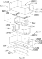
- the reflection driving mechanism 12 comprises a reflection drive housing 121, a bearing seat 122, a support frame 123, a spring sheet 124, a driving unit 125, a reflection part magnetic attraction component 127 and a rotation support assembly 128.
- the imaging light is reflected by the reflection module 10 and then emitted and propagates to the optical lens 22.
- the emission direction of the reflection module 10 is consistent with the optical axis direction of the optical lens 22, both of which are the Z-axis direction.
- the incident direction of the imaging light entering the reflection module 10 is the Y-axis direction (the second axis 123Y direction), and the direction perpendicular to both the incident and emitting directions of the imaging light is the X-axis direction (the first axis 122X direction).
- the reflection drive housing 121 has a receiving cavity and a light inlet 1213 and a light outlet 1214 connected to the receiving cavity.
- the imaging light from the object to be photographed enters the reflection drive housing 121 from the light inlet 1213, is reflected on the reflective element 11, and leaves the reflection drive housing 121 from the light outlet 1214.
- the reflection drive housing 121 comprises an upper cover 1211 and a base 1212.
- the upper cover 1211 is fixed to the base 1212 and forms an installation space of the reflection drive housing 121 to install other elements of the reflection driving mechanism 12.
- the upper cover 1211 comprises an upper cover body 12111 and a first upper cover side wall 12112, a second upper cover side wall 12113, a third upper cover side wall 12114 and a fourth upper cover side wall 12115 extending integrally on the periphery of the upper cover body 12111.
- the upper cover body 12111, the first upper cover side wall 12112, the second upper cover side wall 12113, the third upper cover side wall 12114 and the fourth upper cover side wall 12115 form an accommodating cavity of the upper cover 1211 to accommodate the base 1212.
- the first upper cover side wall 12112 and the second upper cover side wall 12113 are relatively arranged on both sides of the upper cover body 12111, the third upper cover side wall 12114 connects the first upper cover side wall 12112 and the second upper cover side wall 12113 and is arranged on a side of the upper cover body 12111, and the fourth upper cover side wall 12115 connects the first upper cover side wall 12112 and the second upper cover side wall 12113 and is arranged on the other side of the upper cover body 12111 opposite to the third upper cover side wall 12114.
- the fourth upper cover side wall 12115 is located at a side of the reflection module 10 from which the imaging light is emitted, that is, the fourth upper cover side wall 12115 is located at a side of the upper cover 1211 close to the lens module 20.
- the upper cover 1211 comprises an upper cover light inlet 121111 formed on the upper cover body 12111 and an upper cover light outlet 121151 formed on the fourth upper cover side wall 12115.
- the upper cover light inlet 121111 provides a channel for the imaging light to be incident
- the upper cover light outlet 121151 provides a channel for the imaging light to be emitted.
- the upper cover light inlet 121111 and the upper cover light outlet 121151 are connected to provide space for the reflective element 11 to move, thereby reducing the avoidance space provided by the reflection drive housing 121 to the reflective element 11 and reducing the size of the reflection driving mechanism 12.
- the upper cover light inlet 121111 and the upper cover light outlet 121151 are not connected, thereby reducing stray light entering the lens module 20.
- the base 1212 comprises a substrate 12121 and a first base side wall 12122, a second base side wall 12123, a third base side wall 12124 and a fourth base side wall 12125 surrounding the substrate 12121 and fixed to the substrate 12121.
- the base 1212 has an upward opening and forms an installation space together with the upper cover 1211.
- the first base side wall 12122 and the second base side wall 12123 are relatively arranged on both sides of the substrate 12121, the third base side wall 12124 connects the first base side wall 12122 and the second base side wall 12123 and is arranged on a side of the substrate 12121, and the fourth base side wall 12125 connects the first base side wall 12122 and the second base side wall 12123 and is arranged on the other side of the substrate 12121 opposite to the third base side wall 12124.
- the fourth base side wall 12125 is located on the side of the reflection module 10 from which the imaging light is emitted, that is, the fourth base side wall 12125 is located on the side of the base 1212 close to the lens module 20.
- the base 1212 comprises a base light outlet 121251 formed in the fourth base side wall 12125, and the base light outlet 121251 provides a channel for the imaging light to exit.
- the base 1212 is formed by the substrate 12121 and the first base side wall 12122, the second base side wall 12123, the third base side wall 12124 and the fourth base side wall 12125.
- the upward opening and the upper cover light inlet 121111 of the upper cover 1211 together constitute the light inlet 1213 of the reflection drive housing 121.
- the base light outlet 121251 of the base 1212 and the upper cover light outlet 121151 of the upper cover 1211 together constitute the light outlet 1214 of the reflection drive housing 121.
- the reflective element 11 is installed in the reflection driving mechanism 12 by being fixed to the bearing seat 122
- the bearing seat 122 is installed in the support frame 123 and is directly or indirectly supported by the support frame 123
- the support frame 123 is installed in the reflection drive housing 121 and is directly or indirectly supported by the reflection drive housing 121.
- the bearing seat 122 is rotatably mounted on the support frame 123
- the support frame 123 is also rotatably mounted in the reflection drive housing 121.
- the reflective element 11 is installed on the bearing seat 122, when the bearing seat 122 and/or the support frame 123 rotate relative to the reflection drive housing 121, the reflective element 11 is also driven to rotate relative to the reflection drive housing 121 to achieve optical image stabilization of the camera module 1.
- the bearing seat 122 comprises a bearing body 1221 having a mounting portion, wherein the mounting portion is recessedly formed on a side of the bearing seat 122 close to the side where the reflection module 10 emits the imaging light.
- the reflective element 11 is fixed to the bearing seat 122 by being mounted on the mounting portion.
- the bearing seat 122 is suitable for being driven by the driving unit 125 to realize rotation around the first axis 122X (X-axis) and/or the second axis 123Y (Y-axis), thereby driving the reflective element 11 to rotate around the first axis 122X (X-axis) and/or the second axis 123Y (Y-axis).
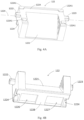
- the support frame 123 comprises a first support portion 1231, a second support portion 1232, and a frame connecting portion 1233 connecting the first support portion 1231 and the second support portion 1232.
- the first support portion 1231, the frame connecting portion 1233, and the second support portion 1232 are integrally formed by injection molding to form a U-shaped opening, and the U-shaped opening faces a side of the bearing seat 122.
- the bearing seat 122 is disposed in the U-shaped opening of the support frame 123 and is surrounded by the support frame 123.
- the bearing seat 122 is suitable for rotating around the first axis 122X (X-axis) relative to the support frame 123.
- the frame connecting portion 1233 comprises a connected connection part body 12331 and a reinforcement member 12332, and the two ends of the connection part body 12331 and the reinforcement member 12332 are respectively connected to the first support portion 1231 and the second support portion 1232, and the reinforcement member 12332 enhances the structural strength of the support frame 123 to prevent the first support portion 1231 and the second support portion 1232 from bending inwardly.
- the bearing seat 122 is rotatably mounted on the support frame 123.
- the bearing seat 122 also comprises a first rotation axis 1222 and a second rotation axis 1223 which protrude from both sides of the bearing body 1221 toward the first support portion 1231 and the second support portion 1232, respectively, and the first axis 122X passes through the rotation axis center of the first rotation axis 1222 and the second rotation axis 1223, and the bearing seat 122 rotates around the rotation axis formed by the first rotation axis 1222 and the second rotation axis 1223.
- the top surface of the support frame 123 is recessed downward to form a first support groove 12311 and a second support groove 12321.
- the first support groove 12311 and the second support groove 12321 are symmetrically formed on the inner side of the first support portion 1231 and the inner side of the second support portion 1232, respectively.
- the first rotation axis 1222 is supported on the first support groove 12311, and the second rotation axis 1223 is supported on the second support groove 12321, so that the bearing seat 122 is supported on the support frame 123.
- At least a portion of the top surface of the support frame 123 is recessed downward to form the first support groove 12311 and the second support groove 12321, so that the assembly of the reflection driving mechanism 12 becomes simple, and it is only necessary to stack the components along the height direction (i.e., the Y-axis direction).
- the bottom surfaces of the first rotation axis 1222 and the second rotation axis 1223 contacting the support frame 123 have a curved surface shape, which may be a part of a cylindrical surface, a part of a spherical surface, or other types of curved surface shapes.
- the bottom surface of the first rotation axis 1222 contacts at least two surfaces of the first support groove 12311, and the bottom surface of the second rotation axis 1223 contacts at least two surfaces of the second support groove 12321, so that the first rotation axis 1222 is supported by the first support groove 12311 and rotates in the first support groove 12311, and the second rotation axis 1223 is supported by the second support groove 12321 and rotates in the second support groove 12321.
- the first support groove 12311 and the second support groove 12321 may be in a V-shaped groove, a rectangular groove, a trapezoidal groove, etc., but the present application is not limited thereto.
- the bearing seat 122 rotates around the first axis 122X by relying on the rotation of the first rotation axis 1222 in the first support groove 12311 and the rotation of the second rotation axis 1223 in the second support groove 12321.
- the rotation axis of the first rotation axis 1222 and the rotation axis of the second rotation axis 1223 are coaxially arranged, and the axes of the two are at the same height.
- the first rotation axis 1222 and the second rotation axis 1223 are located at the top of the bearing seat 122.
- the bearing seat 122 is rotatably connected to the support frame 123 via a pivot connection structure so that the bearing seat 122 can rotate relative to the support frame 123.
- the pivot connection structure refers to a structure in which a first object provided with the axis can rotate relative to a second object provided with the groove through cooperation between the axis and the groove. It is particularly worth mentioning that, on the one hand, the pivot connection structure allows the bearing seat 122 to rotate relative to the support frame 123, and on the other hand, when the bearing seat 122 and the support frame 123 are rotated as a whole, the relative position relationship between the bearing seat 122 and the support frame 123 as sub-parts will not change easily.
- the bearing seat 122 is taken as an example to comprise the first rotation axis 1222 and the second rotation axis 1223, it should be understood that in the embodiment of the present application, the bearing seat 122 may only comprise at least one rotation axis, and accordingly, the support frame 123 may also be configured with only one support groove, so that the bearing seat 122 can rotate relative to the support frame 123 through the pivot connection between the at least one rotation axis and the at least one support groove.
- the reflection driving mechanism 12 further comprises a first rotation limiting portion disposed between the bearing seat 122 and the support frame 123.
- a first rotation limiting portion disposed between the bearing seat 122 and the support frame 123.
- at least a portion of the first support portion 1231 protrudes toward the direction of the bearing seat 122 to form a first limiting protrusion 12315
- at least a portion of the side of the bearing seat 122 opposite to the first support portion 1231 is recessed to form a first limiting groove 1224
- the first limiting protrusion 12315 cooperates with the first limiting groove 1224 to limit the rotation angle of the bearing seat 122 relative to the support frame 123 around the first axis 122X (X-axis).
- the second support portion 1232 protrudes toward the direction of the bearing seat 122 to form a second limiting protrusion 12325, and at least a portion of the side of the bearing seat 122 opposite to the second support portion 1232 is recessed to form a second limiting groove 1225, and the second limiting protrusion 12325 cooperates with the second limiting groove 1225 to limit the rotation angle of the bearing seat 122 relative to the support frame 123 around the first axis 122X (X-axis).
- the first limiting protrusion 12315 is located at the bottom of the first support portion 1231
- the second limiting protrusion 12325 is located at the bottom of the second support portion 1232
- the first limiting protrusion 12315 and the second limiting protrusion 12325 are symmetrically arranged on the inner side of the support frame 123, so that the first rotation limiting portion is relatively far away from the first axis 122X, so that the rotation angle of the bearing seat 122 relative to the support frame 123 around the first axis 122X (X-axis) is larger.
- a maximum rotation angle of the bearing seat 122 relative to the support frame 123 around the first axis 122X (X-axis) is 2°.
- the support frame 123 is rotatably installed in the reflection drive housing 121.
- the support frame 123 is rotatably installed in the reflection drive housing 121 through a rotation support assembly 128, so that the support frame 123 can rotate relative to the reflection drive housing 121.
- the rotation support assembly 128 is arranged between the support frame 123 and the reflection drive housing 121, so that the support frame 123 is supported on the reflection drive housing 121 through the rotation support assembly 128 and rotates relative to the driving shell around the second axis 123Y (Y-axis) by means of the rotation support assembly 128.
- the rotation support assembly 128 comprises a rotation track 1281 and at least three balls 1282 disposed in the rotation track 1281, and at least three balls 1282 abut against the rotation track 1281.
- the rotation track 1281 comprises an upper track groove formed on the bottom surface of the frame of the support frame 123 and a lower track groove formed on the reflection drive housing 121, and the upper track groove and the lower track groove hold at least three balls 1282 therein, and at least three balls 1282 are in contact with the upper track groove and the lower track groove.
- the number of the balls 1282 may be three, four, five or more.
- the number of the balls 1282 is greater than or equal to three, at least three of the balls 1282 provide a supporting plane for supporting the support frame 123.
- the interval between the three balls 1282 is 120°.
- the rotation support assembly 128 comprises four ball bearings 1282
- the upper track groove of the rotation track 1281 comprises a first upper track groove 12312, a second upper track groove 12313 recessedly formed on the bottom surface of the first support portion 1231 and a third upper track groove 12322, a fourth upper track groove 12323 recessedly formed on the bottom surface of the second support portion 1232
- the lower track groove of the rotation track 1281 comprises a first lower track groove 121212, a second lower track groove 121213, a third lower track groove 121214 and a fourth lower track groove 121215 recessedly formed on the upper surface of the substrate 12121 of the base 1212.
- the first upper track groove 12312 corresponds to the first lower track groove 121212 and holds the ball 1282 therein
- the second upper track groove 12313 corresponds to the second lower track groove 121213 and holds the ball 1282 therein
- the third upper track groove 12322 corresponds to the third lower track groove 121214 and holds the ball 1282 therein
- the fourth upper track groove 12323 corresponds to the fourth lower track groove 121215 and holds the ball 1282 therein.
- the first lower track groove 121212, the second lower track groove 121213, the third lower track groove 121214 and the fourth lower track groove 121215 are arc-shaped track grooves and are distributed on a circular trajectory.
- the second axis 123Y (Y-axis) passes through the center of the circular trajectory.
- the first upper track groove 12312, the second upper track groove 12313, the third upper track groove 12322 and the fourth upper track groove 12323 are also arc-shaped track grooves and are distributed on a circular trajectory of the same size.
- the reflection driving mechanism 12 further comprises a second rotation limiting portion disposed between the support frame 123 and the base 1212. Specifically, referring to Figs. 5A to 7 , at least a portion of the outer side surface of the first support portion 1231 close to the base 1212 is recessed to form a third limiting groove 12314, and at least a portion of the side of the base 1212 opposite to the first support portion 1231 is protruded to form a third limiting protrusion 121221.
- the third limiting groove 12314 and the third limiting protrusion 121221 cooperate to limit the rotation angle of the support frame 123 around the second axis 123Y (Y-axis).
- at least a portion of the outer side surface of the second support portion 1232 close to the base 1212 is recessed to form a fourth limiting groove 12324, and at least a portion of the side of the base 1212 opposite to the second support portion 1232 is protruded to form a fourth limiting protrusion 121231.
- the fourth limiting groove 12324 and the fourth limiting protrusion 121231 cooperate to limit the rotation angle of the support frame 123 around the second axis 123Y (Y-axis).
- the third limiting groove 12314 is formed on the outer side of the first support portion 1231
- the fourth limiting groove 12324 is formed on the outer side of the second support portion 1232
- the third limiting protrusion 121221 is formed on the inner side of the first base side wall 12122
- the fourth limiting protrusion 121231 is formed on the inner side of the second base side wall 12123, so that the second rotation limiting portion is relatively far away from the second axis 123Y, so that the rotation angle of the support frame 123 relative to the base 1212 around the second axis 123Y (Y-axis) is larger.
- the maximum rotation angle of the support frame 123 relative to the base 1212 around the second axis 123Y (Y-axis) is 4°.
- the driving unit 125 is disposed between the bearing seat 122 and the base 1212, so as to drive the bearing seat 122 to move, and realize the bearing seat 122 to rotate relative to the support frame 123 around the first axis 122X (X-axis) through the first rotation axis 1222, the second rotation axis 1223, the first support groove 12311 and the second support groove 12321.
- the support frame 123 is then driven to move by the contact between the bearing seat 122 and the support frame 123, and the support frame 123 is rotated relative to the base 1212 around the second axis 123Y (Y-axis) by the rotation support assembly 128.
- a pivot connection structure is provided between the bearing seat 122 and the support frame 123 so that the bearing seat 122 can rotate relative to the support frame 123
- a rotation support assembly 128 is provided between the support frame 123 and the reflection drive housing 121 so that the support frame 123 can rotate relative to the reflection drive housing 121.
- bearing seat 122 and the support frame 123 can also be rotatably installed through a rotation support assembly 128, or the support frame 123 and the reflection drive housing 121 can also be rotatably installed through a pivot connection structure, it is preferred to realize the rotatable installation between the bearing seat 122 and the support frame 123 with a pivot connection structure and realize the rotatable installation between the support frame 123 and the reflection drive housing 121 through a rotation support assembly 128.
- the pivot connection relationship between the bearing seat 122 and the support frame 123 can ensure that relative movement between the two will not occur easily, that is, the stabilization control of the camera module 1 is more accurate in the direction around the second axis 123Y.
- the driving unit 125 is arranged between the bearing seat 122 and the base 1212, that is, the driving unit 125 is far away from the pivot connection structure, so that only a relatively smaller force is required to drive the bearing seat 122 to rotate relative to the support frame 123, that is, the stabilization of the camera module 1 in the direction around the first axis 122X is easier to drive and control.
- the driving unit 125 is implemented as at least two coil-magnet pairs, and the at least two coil-magnet pairs comprise at least two coils arranged in one of the bearing seat 122 and the base 1212 and at least two magnets arranged in the other of the bearing seat 122 and the base 1212, and the at least two coils correspond to the at least two magnets.
- the at least two coil-magnet pairs comprise at least two coils arranged in one of the bearing seat 122 and the base 1212 and at least two magnets arranged in the other of the bearing seat 122 and the base 1212, and the at least two coils correspond to the at least two magnets.
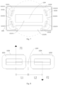
- the driving unit 125 comprises two coil-magnet pairs, and the driving unit 125 comprises a first driving magnet 1252 and a second driving magnet 1254 fixed to the bearing seat bottom surface 122B of the bearing seat 122, and a first driving coil 1251 and a second driving coil 1253 respectively corresponding to the first driving magnet 1252 and the second driving magnet 1254 and directly or indirectly fixed to the substrate 12121 of the base 1212.
- the first driving magnet 1252 and the second driving magnet 1254 are symmetrically arranged on the bearing seat bottom surface 122B of the bearing seat.
- the reflection driving mechanism 12 comprises a reflection part circuit board 126 for providing current to the driving unit 125, the reflection part circuit board 126 is fixed to the base 1212, the first driving coil 1251 and the second driving coil 1253 are fixed and electrically connected to the reflection part circuit board 126, so that the reflection part circuit board 126 provides current to the first driving coil 1251 and the second driving coil 1253.
- the substrate 12121 of the base 1212 has a substrate through hole 121211, the reflection part circuit board 126 is fixed to the bottom surface of the substrate 12121, and then the reflection part circuit board 126 and the substrate through hole 121211 form a coil receiving cavity, and the first driving coil 1251 and the second driving coil 1253 are accommodated in the coil receiving cavity.
- the bearing seat bottom surface 122B of the bearing seat 122 is recessed inward to form a first bearing seat magnet groove 1226 and a second bearing seat magnet groove 1227.
- the first driving magnet 1252 is fixed in the first bearing seat magnet groove 1226
- the second driving magnet 1254 is fixed in the second bearing seat magnet groove 1227, thereby reducing the increase in the size of the reflection driving mechanism 12 caused by the volume of the magnet.
- the first driving coil 1251 and the first driving magnet 1252 are arranged opposite to each other to form a first coil-magnet pair
- the second driving coil 1253 and the second driving magnet 1254 are arranged opposite to each other to form a second coil-magnet pair.
- the first coil-magnet pair provides the bearing seat 122 with a first driving force F1
- the second coil-magnet pair provides the bearing seat 122 with a second driving force F2
- F1 and F2 represent the magnitude and direction of the first driving force and the second driving force, for example, when the first driving force is in opposite directions to the second driving force, one of F1 and F2 is a positive value and the other is a negative value;
- the vertical distance from the first driving force F1 to the rotation axis of the support frame 123 is the first force arm, and the first force arm is L1
- the vertical distance from the second driving force F2 to the rotation axis of the support frame 123 is the second force arm, and the second force arm is L2.
- the direction of the first driving force F1 and the direction of the second driving force F2 are perpendicular to the plane where the first axis 122X (X-axis) and the second axis 123Y (Y-axis) are located, and the rotation axis of the support frame 123 is the second axis 123Y (Y-axis).
- Mo Mo is equal to 0
- Mo the support frame 123 is stationary relative to the base 1212;
- Mo is not equal to 0
- the support frame 123 rotates relative to the base 1212 around the second axis 123Y (Y-axis).
- the positive or negative value of Mo indicates the direction of rotation of the support frame 123.
- the bearing seat 122 rotates relative to the support frame 123, and the support frame 123 rotates relative to the base 1212, so that the bearing seat 122 rotates relative to the base 1212 in two directions, that is, the bearing seat 122 rotates relative to the base 1212 around the first axis 122X (X-axis) and the second axis 123Y (Y-axis).
- the distance between the first force arm L1 and the second force arm L2 is equal.
- the bearing seat 122 rotates relative to the support frame 123 around the first axis 122X (X-axis), and the support frame 123 is stationary relative to the base 1212, so that the bearing seat 122 rotates relative to the base 1212 around the first axis 122X (X-axis);
- the bearing seat 122 is stationary relative to the support frame 123, and the support frame 123 rotates relative to the base 1212 around the second axis 123Y (Y-axis), so that the bearing seat 122 rotates relative to the base 1212 around the second axis 123Y (Y-axis).
- the bearing seat 122 rotates relative to the support frame 123 around the first axis 122X (X-axis), and the support frame 123 rotates relative to the base 1212 around the second axis 123Y (Y-axis), so that the bearing seat 122 rotates relative to the base 1212 around the first axis 122X (X-axis) and the second axis 123Y (Y-axis).
- the first driving magnet 1252 and the second driving magnet 1254 are suitable for being formed on the same magnet. That is, in some embodiments of the present application, the first driving magnet 1252 and the second driving magnet 1254 have an integrated structure, which is essentially one magnet. Accordingly, in this embodiment, the first bearing seat magnet groove 1226 and the second bearing seat magnet groove 1227 are connected to accommodate the connected first driving magnet 1252 and the second driving magnet 1254.
- the reflection driving mechanism 12 also comprises a position sensing unit 129.
- the position sensing unit 129 comprises a first position sensing element 1291 and a second position sensing element 1292 fixed and electrically connected to the reflection part circuit board 126.
- the first position sensing element 1291 and the second position sensing element 1292 obtain the position information of the magnet on the bearing seat 122 to determine the position information of the bearing seat 122.
- the first position sensing element 1291 is arranged opposite to the first driving magnet 1252
- the second position sensing element 1292 is arranged opposite to the second driving magnet 1254.
- the first position sensing element 1291 is eccentrically arranged in the first driving coil 1251
- the second position sensing element 1292 is eccentrically arranged in the second driving coil 1253.
- the reflection driving mechanism 12 further comprises a reflection part magnetic attraction component 127.
- the reflection part magnetic attraction component 127 comprises a reflection part magnetic conductive sheet 1271, a frame magnetic attraction magnet 1273 and a bearing magnetic attraction magnet 1272, wherein the frame magnetic attraction magnet 1273 is fixed to the frame bottom surface 123B of the support frame 123, and the reflection part magnetic conductive sheet 1271 is directly or indirectly fixed to the substrate 12121, and the magnetic attraction force between the frame magnetic attraction magnet 1273 and the reflection part magnetic conductive sheet 1271 enables at least three balls 1282 to be held between the support frame 123 and the substrate 12121, and thus the support frame 123 can be supported on the substrate 12121 by at least three balls 1282.
- the bearing magnetic attraction magnet 1272 is fixed to the bearing seat bottom surface 122B of the bearing seat 122 and is opposite to the reflection part magnetic conductive sheet 1271, and the bearing seat 122 can be supported on the support frame 123 by the magnetic attraction force between the bearing magnetic attraction magnet 1272 and the reflection part magnetic conductive sheet 1271.
- the frame magnetic attraction magnet 1273 comprises a first frame magnetic attraction magnet 12731 and a second frame magnetic attraction magnet 12732, the bottom surface of the first support portion 1231 is recessed inward to form a first support frame magnetic groove 12316, the bottom surface of the second support portion 1232 is recessed inward to form a second support frame magnetic groove 12326, the first frame magnetic attraction magnet 12731 is disposed in the first support frame magnetic groove 12316, and the second frame magnetic attraction magnet 12732 is disposed in the second support frame magnetic groove 12326, thereby reducing the size of the reflection driving mechanism 12.
- the bearing magnetic attraction magnet 1272 may be a first driving magnet 1252 and a second driving magnet 1254.
- the reflection part magnetic conductive sheet 1271 is attached to the side of the reflection part circuit board 126 away from the frame magnetic attraction magnet 1273, so that the reflection part magnetic conductive sheet 1271 can provide structural reinforcement for the reflection part circuit board 126 while attracting the magnet.
- the reflection part magnetic conductive sheet 1271 is made of a material that can attract the magnet, such as an iron sheet.
- the outer fixing portion 1241 comprises a first outer fixing portion 12411, a second outer fixing portion 12412, a third outer fixing portion 12413 and a fourth outer fixing portion 12414
- the inner fixing portion 1243 comprises a first inner fixing portion 12431, a second inner fixing portion 12432, a third inner fixing portion 12433 and a fourth inner fixing portion 12434
- the spring wire portion 1242 comprises a first spring wire 12421 and a second spring wire 12422.
- the first outer fixing portion 12411 and the second outer fixing portion 12412 are fixed to the top surface of the first support portion 1231, the first inner fixing portion 12431 and the second inner fixing portion 12432 are fixed to a side of the bearing seat top surface 122A of the bearing seat 122 close to the first support portion 1231, and the first spring wire 12421 connects the first outer fixing portion 12411, the second outer fixing portion 12412, the first inner fixing portion 12431, and the second inner fixing portion 12432 to form a first spring sheet part.
- the third outer fixing portion 12413 and the fourth outer fixing portion 12414 are fixed to the top surface of the second support portion 1232, the third inner fixing portion 12433 and the fourth inner fixing portion 12434 are fixed to a side of the bearing seat top surface 122A of the bearing seat 122 close to the second support portion 1232, and the second spring wire 12422 connects the third outer fixing portion 12413, the fourth outer fixing portion 12414, the third inner fixing portion 12433, and the fourth inner fixing portion 12434 to form a second spring sheet part.
- the first spring sheet part and the second spring sheet part are symmetrical about the second axis 123Y (Y-axis), so that the bearing seat 122 is centrally disposed in the support frame 123.
- the bearing seat 122 further comprises four first fixing protrusions 122A1 formed on the bearing seat top surface 122A of the bearing seat, and the first inner fixing portion 12431, the second inner fixing portion 12432, the third inner fixing portion 12433 and the fourth inner fixing portion 12434 are respectively fixed to the bearing seat top surface 122A of the bearing seat by being fixed to the first fixing protrusions 122A1.
- the support frame 123 also comprises four second fixing protrusions 123A1 formed on the frame top surface 123A, and the first outer fixing portion 12411, the second outer fixing portion 12412, the third outer fixing portion 12413 and the fourth outer fixing portion 12414 are respectively fixed to the frame top surface 123A by being fixed to the second fixing protrusions 123A1.
- the first spring wire 12421 has a first spring wire rotation axis 124211, and the first spring wire 12421 is symmetrical about the first spring wire rotation axis 124211.
- the second spring wire 12422 has a second spring wire rotation axis 124221, and the second spring wire 12422 is symmetrical about the second spring wire rotation axis 124221.
- the first spring wire rotation axis 124211 and the second spring wire rotation axis 124221 are in the same direction as the first axis 122X (X-axis). In this way, when the bearing seat 122 rotates around the first axis 122X (X-axis) relative to the support frame 123, the spring sheet 124 has a small resistance to rotation.
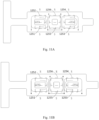
- the driving unit 125 comprises three coil-magnet pairs, and the driving unit 125 comprises a first driving magnet 1252, a second driving magnet 1254, and a third driving magnet 1256 fixed to the bearing seat bottom surface 122B of the bearing seat 122, and a first driving coil 1251, a second driving coil 1253, and a third driving coil 1255 corresponding to the first driving magnet 1252, the second driving magnet 1254, and the third driving magnet 1256, respectively, and directly or indirectly fixed on the substrate 12121 of the base 1212, the first driving magnet 1252 and the second driving magnet 1254 are symmetrically arranged on the bearing seat bottom surface 122B of the bearing seat, and the third driving magnet 1256 is arranged between the first driving magnet 1252 and the second driving magnet 1254.
- the reflection part circuit board 126 is fixed to the bottom surface of the substrate 12121, and the reflection part circuit board 126 and the substrate through hole 121211 form a coil receiving cavity, and the first driving coil 1251, the second driving coil 1253 and the third driving coil 1255 are accommodated in the coil receiving cavity.
- the bearing seat bottom surface 122B of the bearing seat 122 is recessed inward to form a first bearing seat magnet groove 1226, a second bearing seat magnet groove 1227 and a third bearing seat magnet groove 1228.
- the first driving coil 1251 and the first driving magnet 1252 are arranged opposite to each other to form a first coil-magnet pair
- the second driving coil 1253 and the second driving magnet 1254 are arranged opposite to each other to form a second coil-magnet pair
- the third driving coil 1255 and the third driving magnet 1256 are arranged opposite to each other to form a third coil-magnet pair.
- the first coil-magnet pair provides the bearing seat 122 with a first driving force F1
- the second coil-magnet pair provides the bearing seat 122 with a second driving force F2
- the third coil-magnet pair provides the bearing seat 122 with a third driving force F3.
- F1, F2, and F3 represent the magnitude and direction of the first driving force, the second driving force, and the third driving force. For example, when the first driving force is in opposite directions to the second driving force, one of F1 and F2 is a positive value, and the other is a negative value.
- the vertical distance from the first driving force F1 to the rotation axis of the support frame 123 is the first force arm, which is L1; the vertical distance from the second driving force F2 to the rotation axis of the support frame 123 is the second force arm, which is L2; the third coil-magnet pair is located in the middle, and the distance L3 from the third driving force F3 to the rotation axis of the support frame 123 is 0.
- the directions of the first driving force F1, the second driving force F2 and the third driving force F3 are perpendicular to the plane where the first axis 122X (X-axis) and the second axis 123Y (Y-axis) are located, and the rotation axis of the support frame 123 is the second axis 123Y (Y-axis).
- the distances between the first force arm L1 and the second force arm L2 are equal, and the distance L3 from the third driving force F3 to the rotation axis of the support frame 123 is 0.
- the third driving force F3 provided by the third coil-magnet pair located in the middle is used to drive the bearing seat 122 to rotate around the first axis 122X (X-axis) relative to the base 1212, and the first coil-magnet pair and the second coil-magnet pair symmetrically arranged on both sides are suitable for driving the bearing seat 1212 to rotate around the first axis 122X (X-axis) and the second axis 123Y (Y-axis).
- the third coil-magnet pair is suitable for driving the bearing seat 122 to rotate relative to the support frame 123 around the first axis 122X
- the first coil-magnet pair and the second coil-magnet pair are suitable for cooperating to drive the bearing seat 122 to rotate relative to the reflection drive housing 121 around the second axis 123Y perpendicular to the first axis 122X so as to drive the support frame 123 to rotate relative to the reflection drive housing 121 around the second axis 123Y through the pivot connection between the bearing seat 122 and the support frame 123.
- the first driving force F1 and the second driving force F2 are not equal in magnitude, the first driving force F1, the second driving force F2 and the third driving force F3 together drive the bearing seat 122 to rotate relative to the base 1212 around the first axis 122X (X-axis) and the second axis 123Y (Y-axis).
- the current directions in the first driving coil 1251 and the second driving coil 1253 are controlled to be the same (the winding methods of the first driving coil 1251 and the second driving coil 1253 are set to be consistent), thereby providing driving forces in opposite directions to always maintain the current directions in opposite directions.
- the winding methods of the first driving coil 1251 and the second driving coil 1253 can also be adjusted so that the directions of the forces generated by the first coil-magnet pair and the second coil-magnet pair acting on the bearing seat 122 are opposite.
- the reflection driving mechanism 12 also has an anti-fool mechanism.
- the first driving coil 1251 and the second driving coil 1253 are connected in series and the winding directions of the first driving coil 1251 and the second driving coil 1253 are opposite, so that when the magnetic pole directions of the first driving magnet 1252 and the second driving magnet 1254 are opposite, the current directions in the first driving coil 1251 and the second driving coil 1253 are the same, thereby providing driving forces in opposite directions.
- the first driving coil 1251 and the second driving coil 1253 are connected in series, the winding direction of the first driving coil 1251 is opposite to the winding direction of the second driving coil 1253, and the magnetic poles of the first driving magnet 1252 and the second driving magnet 1254 are in the same direction.
- the first driving coil 1251 and the second driving coil 1253 may be connected in series, the winding direction of the first driving coil 1251 is the same as the winding direction of the second driving coil 1253, and the magnetic poles of the first driving magnet 1252 and the second driving magnet 1254 are in opposite directions.
- the three coil-magnet pairs and the first coil-magnet pairs and the second coil-magnet pairs respectively drive the bearing seat 122 to rotate relative to the support frame 123 around the first axis 122X (X-axis) and drive the support frame 123 to rotate relative to the base 1212 around the second axis 123Y (Y-axis).
- the first driving force F1 and the second driving force F2 have opposite directions and equal magnitudes, so that the resultant force of the first driving force F1 and the second driving force F2 is 0, and can only drive the support frame 123 to rotate around the second axis 123Y (Y-axis) relative to the base 1212, and then, the bearing seat 122 is controlled to rotate around the first axis 122X (X-axis) relative to the support frame 123 by the magnitude of the third driving force F3, and the rotation direction of the bearing seat 122 relative to the support frame 123 around the first axis 122X (X-axis) is controlled by the direction of the third driving force F3.
- the first driving magnet 1252, the second driving magnet 1254 and the third driving magnet 1256 are suitable for being formed on the same magnet.
- the first bearing seat magnet groove 1226, the second bearing seat magnet groove 1227 and the third bearing seat magnet groove 1228 are connected to accommodate the connected first driving magnet 1252, the second driving magnet 1254 and the third driving magnet 1256.
- the reflection driving mechanism 12 also comprises a position sensing unit 129.
- the position sensing unit 129 comprises a first position sensing element 1291 and a second position sensing element 1292 fixed and electrically connected to the reflection part circuit board 126.
- the first position sensing element 1291 and the second position sensing element 1292 obtain the position information of the magnet on the bearing seat 122 to determine the position information of the bearing seat 122.
- the first position sensing element 1291 is arranged opposite to the first driving magnet 1252
- the second position sensing element 1292 is arranged opposite to the second driving magnet 1254.
- the first position sensing element 1291 is eccentrically arranged in the first driving coil 1251, and the second position sensing element 1292 is eccentrically arranged in the second driving coil 1253.
- the reflection part magnetic attraction component 127 is disposed between the bottom surface of the bearing seat 122, the bottom surface of the support frame 123 and the substrate 12121 of the base 1212, so that the bearing seat 122 and the support frame 123 are attracted to the substrate 12121 by magnetic attraction force, preventing the bearing seat 122 and the support frame 123 from falling due to the movement of the reflection driving mechanism 12.
- the reflection part magnetic attraction component 127 comprises a reflection part magnetic conductive sheet 1271, a frame magnetic attraction magnet 1273 and a bearing magnetic attraction magnet 1272.
- the frame magnetic attraction magnet 1273 is fixed to the frame bottom surface 123B of the support frame 123.
- the reflection part magnetic conductive sheet 1271 is directly or indirectly fixed to the substrate 12121.
- the magnetic attraction force between the frame magnetic attraction magnet 1273 and the reflection part magnetic conductive sheet 1271 allows at least three balls 1282 to be held between the support frame 123 and the substrate 12121, and the support frame 123 can be supported on the substrate 12121 by at least three balls 1282.
- the bearing magnetic attraction magnet 1272 is fixed to the bearing seat bottom surface 122B of the bearing seat 122 and is opposite to the reflection part magnetic conductive sheet 1271, and the bearing seat 122 can be supported on the support frame 123 by the magnetic attraction force between the bearing magnetic attraction magnet 1272 and the reflection part magnetic conductive sheet 1271.
- the frame magnetic attraction magnet 1273 comprises a first frame magnetic attraction magnet 12731 and a second frame magnetic attraction magnet 12732, the bottom surface of the first support portion 1231 is recessed inward to form a first support frame magnetic groove 12316, the bottom surface of the second support portion 1232 is recessed inward to form a second support frame magnetic groove 12326, the first frame magnetic attraction magnet 12731 is disposed in the first support frame magnetic groove 12316, and the second frame magnetic attraction magnet 12732 is disposed in the second support frame magnetic groove 12326, thereby reducing the size of the reflection driving mechanism 12.
- the bearing magnetic attraction magnet 1272 may be a first driving magnet 1252, a second driving magnet 1254, and a third driving magnet 1256.
- the reflection part magnetic conductive sheet 1271 is attached to the side of the reflection part circuit board 126 away from the frame magnetic attraction magnet 1273, so that the reflection part magnetic conductive sheet 1271 can provide structural reinforcement for the reflection part circuit board 126 while attracting the magnet.
- the reflection part magnetic conductive sheet 1271 is a material that can attract the magnet, such as an iron sheet.
- the camera module 1 and its reflection driving mechanism 12 according to the embodiment of the present application are explained, wherein the reflection driving mechanism 12 drives the reflective element 11 of the camera module 1 to rotate through a compact structural arrangement to achieve optical image stabilization of the camera module 1. Moreover, the reflective stabilization mechanism has a relatively small size, which is conducive to the miniaturization of the camera module 1.
Landscapes
- Physics & Mathematics (AREA)
- General Physics & Mathematics (AREA)
- Optics & Photonics (AREA)
- Engineering & Computer Science (AREA)
- Multimedia (AREA)
- Signal Processing (AREA)
- Lens Barrels (AREA)
- Studio Devices (AREA)
- Adjustment Of Camera Lenses (AREA)
Abstract
Description
- The present application relates to the field of camera modules, and in particular to a reflection driving mechanism and a camera module.
- With the popularity of mobile electronic devices, the relevant technologies of camera modules used in mobile electronic devices to help users obtain images have been rapidly developed and improved. Camera modules have been widely installed in mobile electronic devices such as tablet computers, laptops and smart phones, and Auto Focus (AF) function, Optical Image Stabilization (OIS) function, zoom function, etc. have been added to camera modules for mobile terminals to meet consumers, increasingly diverse requirements for camera module functions.
- However, in order to achieve various functions, the structure of the camera module has become complicated and the size has increased accordingly, resulting in an increase in the size of mobile electronic devices equipped with camera modules. In addition, when it is necessary to drive one of the components in the camera module to move, the weight of the component itself and the weight of other components fixed to the component should also be considered. Driving heavier objects requires greater driving force and higher power consumption.
- Therefore, an optimized stabilization solution and a corresponding camera module structure are expected.
- An advantage of the present application is to provide a reflection driving mechanism and a camera module. The reflection driving mechanism drives the reflective element of the camera module to rotate through a compact structural arrangement to achieve optical image stabilization of the camera module. In particular, the reflective stabilization mechanism has a relatively small size, which is conducive to the miniaturization of the camera module.
- Other advantages and features of the present application will become apparent from the following description, and may be achieved by the means and combinations particularly pointed out in the claims.
- To achieve at least one of the above advantages, the present application provides a reflection driving mechanism, comprising:
- a reflection drive housing having a receiving cavity formed therein and a light inlet and a light outlet communicated with the receiving cavity;
- a rotation support assembly;
- a support frame rotatably mounted in the receiving cavity through the rotation support assembly, wherein the support frame has at least one support groove recessedly formed on its top surface;
- a bearing seat rotatably mounted on the support frame, wherein the bearing seat comprises a bearing body and at least one rotation axis protruding and extending laterally from the bearing body, the bearing body has a mounting portion suitable for mounting a reflective element thereon, and the at least one rotation axis is fittedly mounted in the at least one support groove, so that the bearing seat can rotate relative to the support frame through the pivot connection between the at least one rotation axis and the at least one support groove; and
- a driving unit, wherein the driving unit is suitable for driving the bearing seat to rotate relative to the support frame around a first axis set by the at least one rotation axis, and the driving unit is suitable for driving the bearing seat to rotate relative to the reflection drive housing around a second axis perpendicular to the first axis so as to drive the support frame to rotate relative to the reflection drive housing around the second axis through the pivot connection between the bearing seat and the support frame.
- In the reflection driving mechanism according to the present application, the at least one rotation axis comprises a first rotation axis and a second rotation axis extending outward from opposite sides of the bearing body, respectively, and the first rotation axis and the second rotation axis are coaxially arranged, and the at least one support groove comprises a first support groove and a second support groove recessedly formed on the top surface of the support frame, and the first support groove and the second support groove are coaxially arranged, wherein the first rotation axis is fitted in the first support groove, and the second rotation axis is fitted in the second support groove.
- In the reflection driving mechanism according to the present application, the first rotation axis and the second rotation axis are located on the top of the bearing body.
- In the reflection driving mechanism according to the present application, the support frame comprises a first support portion, a second support portion, and a frame connecting portion extending between the first support portion and the second support portion, wherein the first support groove is recessedly formed on the top surface of the first support portion, and the second support groove is recessedly formed on the top surface of the second support portion.
- In the reflection driving mechanism according to the present application, the outer surface of the first rotation axis contacts at least two surfaces of the first support groove, and the outer surface of the second rotation axis contacts at least two surfaces of the second support groove.
- In the reflection driving mechanism according to the present application, the reflection driving mechanism further comprises a first rotation limiting portion for limiting the rotation angle of the bearing seat relative to the support frame.
- In the reflection driving mechanism according to the present application, the rotation support assembly comprises a rotation track formed between the support frame and the reflection drive housing and at least three balls arranged in the rotation track.
- In the reflection driving mechanism according to the present application, the reflection driving mechanism further comprises a second rotation limiting portion for limiting a rotation angle of the support frame relative to the reflection drive housing.
- In the reflection driving mechanism according to the present application, the driving unit comprises a first driving magnet and a second driving magnet disposed on the bottom surface of the bearing body, and a first driving coil and a second driving coil disposed in the reflection drive housing and corresponding to the first driving magnet and the second driving magnet, respectively. The first driving magnet and the first driving coil constitute a first coil-magnet pair, and the second driving magnet and the second driving coil constitute a second coil-magnet pair.
- In the reflection driving mechanism according to the present application, the reflection drive housing comprises an upper cover and a base that are interlocked with each other, the base has a substrate through hole formed through the bottom thereof, the driving unit also comprises a reflection part circuit board fixed in the substrate through hole, and the first driving coil and the second driving coil are electrically connected to the reflection part circuit board.
- In the reflection driving mechanism according to the present application, the first coil-magnet pair and the second coil-magnet pair are arranged symmetrically relative to a central axis set by the bearing body.
- In the reflection driving mechanism according to the present application, the combined force of a first force acting on the bearing seat generated by the first coil-magnet pair and a second force acting on the bearing seat generated by the second coil-magnet pair determines the movement of the bearing seat relative to the support frame, and the difference between a first torque acting on the bearing seat generated by the first coil-magnet pair and a second torque acting on the bearing seat generated by the second coil-magnet pair determines the movement of the bearing seat and the support frame relative to the reflection drive housing.
- In the reflection driving mechanism according to the present application, the reflection driving mechanism further comprises a reflection part magnetic attraction component for attracting the bearing seat and the support frame to the reflection drive housing. The reflection part magnetic attraction component comprises a frame magnetic attraction magnet fixed to the support frame and a reflection part magnetic conductive sheet arranged on the reflection drive housing, so that the support frame is attracted to the reflection drive housing through the magnetic attraction force between the frame magnetic attraction magnet and the reflection part magnetic conductive sheet and the magnetic attraction force between the first and second driving magnets and the reflection part magnetic conductive sheet, and the bearing seat is attracted to the reflection drive housing through the magnetic attraction force between the first and second driving magnets and the reflection part magnetic conductive sheet.
- In the reflection driving mechanism according to the present application, the reflection driving mechanism also comprises a spring sheet, which comprises an outer fixing portion fixed to the top surface of the support frame, an inner fixing portion fixed to the top surface of the bearing seat, and a spring wire portion extending between the inner fixing portion and the outer fixing portion.
- In the reflection driving mechanism according to the present application, the bearing seat is centrally held in the support frame by the spring sheet.
- In the reflection driving mechanism according to the present application, the outer fixing portion comprises a first outer fixing portion, a second outer fixing portion, a third outer fixing portion and a fourth outer fixing portion, the inner fixing portion comprises a first inner fixing portion, a second inner fixing portion, a third inner fixing portion and a fourth inner fixing portion, and the spring wire portion comprises a first spring wire and a second spring wire. The first outer fixing portion and the second outer fixing portion are fixed to a side of the top surface of the first support portion, the first inner fixing portion and the second inner fixing portion are fixed to a side of the top surface of the bearing seat, and the first spring wire connects the first outer fixing portion, the second outer fixing portion, the first inner fixing portion and the second inner fixing portion to form a first spring sheet part; the third outer fixing portion and the fourth outer fixing portion are fixed to the opposite other side of the top surface of the second support portion, the third inner fixing portion and the fourth inner fixing portion are fixed to the opposite other side of the top surface of the bearing seat, and the second spring wire connects the third outer fixing portion, the fourth outer fixing portion, the third inner fixing portion and the fourth inner fixing portion to form a second spring sheet part, wherein the first spring sheet part and the second spring sheet part are arranged symmetrically with respect to the second axis.
- In the reflection driving mechanism according to the present application, the first spring wire is provided with a first spring wire rotation axis, the first spring wire is symmetrical about the first spring wire rotation axis, the second spring wire is provided with a second spring wire rotation axis, the second spring wire is symmetrical about the second spring wire rotation axis, wherein the first spring wire rotation axis and the second spring wire rotation axis are in the same direction as the first axis.
- The present application provides a reflection driving mechanism, comprising
- a reflection drive housing having a receiving cavity formed therein and a light inlet and a light outlet communicated with the receiving cavity;
- a support frame rotatably mounted in the receiving cavity;
- a bearing seat rotatably mounted on the support frame; and
- a driving unit comprising a first driving magnet and a second driving magnet disposed on the bearing seat, and a first driving coil and a second driving coil disposed on the reflection drive housing and corresponding to the first driving magnet and the second driving magnet, respectively, wherein the first driving magnet and the first driving coil constitute a first coil-magnet pair, and the second driving magnet and the second driving coil constitute a second coil-magnet pair.
- In the reflection driving mechanism according to the present application, the first coil-magnet pair and the second coil-magnet pair are arranged symmetrically relative to the central axis set by the bearing seat.
- In the reflection driving mechanism according to the present application, the first coil-magnet pair and the second coil-magnet pair are suitable for cooperating to drive the bearing seat to rotate around a first axis relative to the support frame, and the first coil-magnet pair and the second coil-magnet pair are suitable for cooperating to drive the bearing seat to rotate around a second axis perpendicular to the first axis relative to the reflection drive housing so as to drive the support frame to rotate around the second axis relative to the reflection drive housing through the pivot connection between the bearing seat and the support frame.
- In the reflection driving mechanism according to the present application, the combined force of the first force acting on the bearing seat generated by the first coil-magnet pair and the second force acting on the bearing seat generated by the second coil-magnet pair determines the movement of the bearing seat relative to the support frame, and the difference between the first torque acting on the bearing seat generated by the first coil-magnet pair and the second torque acting on the bearing seat generated by the second coil-magnet pair determines the movement of the bearing seat and the support frame as a whole relative to the reflection drive housing.
- In the reflection driving mechanism according to the present application, the reflection drive housing comprises an upper cover and a base that are interlocked with each other, the base has a substrate through hole formed through the bottom thereof, the driving unit also comprises a reflection part circuit board fixed in the substrate through hole, and the first driving coil and the second driving coil are electrically connected to the reflection part circuit board.
- In the reflection driving mechanism according to the present application, the driving unit comprises a third driving magnet disposed on the bearing seat and located between the first driving magnet and the second driving magnet, and a third driving coil disposed on the reflection drive housing and corresponding to the third driving magnet, wherein the third driving coil is located between the first driving coil and the second driving coil, wherein the third driving coil and the third driving magnet constitute the third coil-magnet pair.
- In the reflection driving mechanism according to the present application, the first coil-magnet pair and the second coil-magnet pair are symmetrically distributed relative to the third coil-magnet pair.
- In the reflection driving mechanism according to the present application, the third coil-magnet pair is suitable for driving the bearing seat to rotate around a first axis relative to the support frame, and the first coil-magnet pair and the second coil-magnet pair are suitable for cooperating to drive the bearing seat to rotate around a second axis perpendicular to the first axis relative to the reflection drive housing so as to drive the support frame to rotate around the second axis relative to the reflection drive housing through the pivot connection between the bearing seat and the support frame.
- In the reflection driving mechanism according to the present application, the difference between the first torque generated by the first coil-magnet pair acting on the bearing seat and the second torque generated by the second coil-magnet pair acting on the bearing seat determines the movement of the bearing seat and the support frame as a whole relative to the reflection drive housing, wherein the direction of the first force acting on the bearing seat generated by the first coil-magnet pair is opposite to the direction of the second force acting on the bearing seat generated by the second coil-magnet pair.
- In the reflection driving mechanism according to the present application, the magnitude of the first force is equal to the magnitude of the second force.
- In the reflection driving mechanism according to the present application, the first driving coil and the second driving coil are connected in series, the winding direction of the first driving coil is opposite to the winding direction of the second driving coil, and the magnetic poles of the first driving magnet and the second driving magnet are oriented in the same direction.
- In the reflection driving mechanism according to the present application, the first driving coil and the second driving coil are connected in series, the winding direction of the first driving coil is the same as the winding direction of the second driving coil, and the magnetic poles of the first driving magnet and the second driving magnet are in opposite directions.
- In the reflection driving mechanism according to the present application, the reflection driving mechanism also comprises a rotation support assembly, and the support frame is rotatably installed in the receiving cavity through the rotation support assembly, the support frame has at least one support groove recessedly formed on its top surface, the bearing seat comprises a bearing body and at least one rotation axis protruding and extending laterally from the bearing body, the bearing body has a mounting portion suitable for mounting a reflective element thereon, and the at least one rotation axis is fitfully installed in the at least one support groove, so that the bearing seat can be rotated relative to the support frame through the pivot connection between the at least one rotation axis and the at least one support groove.
- In the reflection driving mechanism according to the present application, the at least one rotation axis comprises a first rotation axis and a second rotation axis extending outward from opposite sides of the bearing body, respectively, and the first rotation axis and the second rotation axis are coaxially arranged, and the at least one support groove comprises a first support groove and a second support groove recessedly formed on the top surface of the support frame, and the first support groove and the second support groove are coaxially arranged, wherein the first rotation axis is fitted in the first support groove, and the second rotation axis is fitted in the second support groove, wherein the first rotation axis and the second rotation axis are located on the top of the bearing body.
- In the reflection driving mechanism according to the present application, the support frame comprises a first support portion, a second support portion, and a frame connecting portion extending between the first support portion and the second support portion, wherein the first support groove is recessedly formed on the top surface of the first support portion, and the second support groove is recessedly formed on the top surface of the second support portion.
- In the reflection driving mechanism according to the present application, the reflection driving mechanism further comprises a first rotation limiting portion for limiting the rotation angle of the bearing seat relative to the support frame, and a second rotation limiting portion for limiting the rotation angle of the support frame relative to the reflection drive housing.
- In the reflection driving mechanism according to the present application, the reflection driving mechanism further comprises a reflection part magnetic attraction component for attracting the bearing seat and the support frame to the reflection drive housing. The reflection part magnetic attraction component comprises a frame magnetic attraction magnet fixed to the support frame and a reflection part magnetic conductive sheet arranged on the reflection drive housing, so that the support frame is attracted to the reflection drive housing through the magnetic attraction force between the frame magnetic attraction magnet and the reflection part magnetic conductive sheet and the magnetic attraction force between the first and second driving magnets and the reflection part magnetic conductive sheet, and the bearing seat is attracted to the reflection drive housing through the magnetic attraction force between the first and second driving magnets and the reflection part magnetic conductive sheet.
- In the reflection driving mechanism according to the present application, the reflection driving mechanism further comprises a spring sheet, which comprises an outer fixing portion fixed to the top surface of the support frame, an inner fixing portion fixed to the top surface of the bearing seat, and a spring wire portion extending between the inner fixing portion and the outer fixing portion, wherein the bearing seat is centrally held in the support frame by the spring sheet.
- According to another aspect of the present application, a camera module is also provided, comprising:
- a reflection driving mechanism as described above;
- a reflective element mounted on the reflection driving mechanism;
- a lens module held on a light reflection path of the reflective element; and
- a photosensitive assembly arranged on the light propagation path of the lens module.
- Further objectives and advantages of the present application will be fully reflected through understanding of the following description and drawings.
- These and other objects, features and advantages of the present application are fully reflected in the following detailed description, drawings and claims.
- By describing the embodiments of the present application in more detail in conjunction with the accompanying drawings, the above and other objects, features and advantages of the present application will become more apparent. The accompanying drawings are used to provide further understanding of the embodiments of the present application and constitute a part of the specification. They are used together with the embodiments of the present application to explain the present application and do not constitute a limitation to the present application. In the drawings, the same reference numerals generally refer to the same components or steps.
-
Fig. 1A shows a schematic view of a camera module according to an embodiment of the present application; -
Fig. 1B shows a schematic view of another embodiment of a camera module according to an embodiment of the present application; -
Fig. 1C shows a schematic view of another embodiment of a camera module according to an embodiment of the present application; -
Fig. 2 shows a schematic perspective view of a reflection module according to an embodiment of the present application; -
Fig. 3A shows a perspective exploded schematic top view of a reflection driving mechanism according to an embodiment of the present application; -
Fig. 3B shows an exploded perspective bottom view of the reflection driving mechanism according to an embodiment of the present application; -
Fig. 4A shows a perspective schematic top view of a bearing seat according to an embodiment of the present application; -
Fig. 4B shows a stereoscopic schematic bottom view of the bearing seat according to an embodiment of the present application; -
Fig. 5A shows a perspective schematic top view of a support frame according to an embodiment of the present application; -
Fig. 5B shows a bottom perspective schematic view of the support frame according to an embodiment of the present application; -
Fig. 6A is a perspective schematic view of the reflection driving mechanism according to an embodiment of the present application with the upper cover removed; -
Fig. 6B shows a cross-sectional schematic view of the reflection driving mechanism according to the embodiment of the present application with the upper cover removed; -
Fig. 7 shows a schematic top view of a base according to an embodiment of the present application; -
Fig. 8 shows a schematic view of driving force of two coil-magnet pairs according to an embodiment of the present application; -
Fig. 9 shows a cross-sectional schematic view of another reflection driving mechanism according to an embodiment of the present application with the upper cover removed; -
Fig. 10 is a schematic view illustrating driving forces of three coil-magnet pairs according to an embodiment of the present application; -
Fig. 11A is a schematic view illustrating three coil-magnet pairs according to an embodiment of the present application; -
Fig. 11B shows another schematic view of three coil-magnet pairs according to an embodiment of the present application. - Hereinafter, exemplary embodiments according to the present application will be described in detail with reference to the accompanying drawings. Obviously, the described embodiments are only some embodiments of the present application, rather than all embodiments of the present application. It should be understood that the present application is not limited to the example embodiments described herein.
- As shown in
Fig. 1A to Fig. 1C , a camera module according to an embodiment of the present application is illustrated, which comprises areflection module 10, a lens module 20 and aphotosensitive assembly 30. Thereflection module 10 is used to change the propagation direction of the imaging light from the object to be photographed so that the imaging light points to the lens module 20, the lens module 20 is used to converge the imaging light on thephotosensitive assembly 30, and thephotosensitive assembly 30 is used to output the resulting image. That is to say, in the embodiment of the present application, the function of thereflection module 10 is to redirect the imaging light from the object to be photographed. The lens module 20 is maintained on the reflection path of thereflection module 10 for receiving the imaging light from thereflection module 10, and thephotosensitive assembly 30 is maintained on the light propagation path of the lens module 20 for receiving the imaging light from the lens module 20. - Accordingly, the
reflection module 10 comprises areflection driving mechanism 12 and areflective element 11 attached to thereflection driving mechanism 12. Thereflective element 11 is suitable for reflecting light to fold the imaging optical path of thecamera module 1, thereby reducing the overall height of thecamera module 1 so that thecamera module 1 can be placed horizontally in a mobile electronic device. In a specific example, thereflective element 11 is suitable for deflecting the incident imaging light by 90 degrees and then making it incident on the lens module 20. It is worth mentioning that, considering the manufacturing tolerance, the angle at which thereflective element 11 deflects the imaging light may have an error within 1°, which should be understandable to those skilled in the art. - In a specific embodiment, the
reflective element 11 may be implemented as a reflector or a prism (e.g., a triangular prism). Thereflection driving mechanism 12 is suitable for driving thereflective element 11 to move, thereby changing the propagation path of the imaging light, and further realizing the stabilization function of thecamera module 1. In an embodiment of the present application, with the optical axis direction of the lens module 20 as the Z-axis direction, thereflection driving mechanism 12 is suitable for driving thereflective element 11 to rotate around afirst axis 122X (X-axis) perpendicular to the optical axis (Z-axis) and around asecond axis 123Y (Y-axis) perpendicular to both the optical axis (Z-axis) and thefirst axis 122X (X-axis). - Correspondingly, when the
reflective element 11 is implemented as aprism 111, theprism 111 comprises alight incident surface 1111, alight reflecting surface 1112 and alight exiting surface 1113. Thelight incident surface 1111 of theprism 111 and itslight exiting surface 1113 are perpendicular to each other, and thelight reflecting surface 1112 of theprism 111 is inclined at an angle of 45° to thelight incident surface 1111 and thelight exiting surface 1113. In this way, the imaging light can make a 90° turn at thelight reflecting surface 1112 and be output from thelight exiting surface 1113 in a manner perpendicular to thelight exiting surface 1113. - The lens module 20 comprises an
optical lens 22, the optical axis of theoptical lens 22 is the optical axis of the lens module 20, and the optical axis of theoptical lens 22 is arranged along the Z-axis direction. The light reflected by thereflection module 10 is incident on theoptical lens 22 and converged to thephotosensitive assembly 30 through theoptical lens 22. - In an embodiment of the present application, the
optical lens 22 has a fixed focal length, as shown inFig. 1A , theoptical lens 22 comprises alens barrel 221 and alens group 222 accommodated in thelens barrel 221, thelens group 222 comprises at least one lens, and theoptical lens 22 can move along the optical axis direction of theoptical lens 22 relative to thephotosensitive assembly 30, and can also move along the direction perpendicular to the optical axis of theoptical lens 22. - In other embodiments of the present application, the
optical lens 22 has a variable focal length (i.e., the focal length of the lens module 20 is variable), as shown inFigs. 1 B and 1C, theoptical lens 22 comprises at least onefixed group 223 and at least onemovable group 224, the at least onefixed group 223 is fixed at a distance relative to thephotosensitive assembly 30 along the optical axis direction of theoptical lens 22, and the at least onemovable group 224 is adjustable at a distance relative to the at least onefixed group 223 or thephotosensitive assembly 30 along the optical axis direction of theoptical lens 22. Specifically, referring toFig. 1B , theoptical lens 22 comprises a fixedgroup 223 and amovable group 224, the fixedgroup 223 comprises afirst lens barrel 2231 and afirst lens group 2232 accommodated in thefirst lens barrel 2231, thefirst lens group 2232 comprises at least one lens, and themovable group 224 comprises asecond lens barrel 2241 and asecond lens group 2242 accommodated in thesecond lens barrel 2241, thesecond lens group 2242 comprises at least one lens. In the optical axis direction of theoptical lens 22, the position of the fixedgroup 223 relative to thephotosensitive assembly 30 is fixed, and the position of themovable group 224 relative to the fixedgroup 223 is adjustable, so that the focal length of theoptical lens 22 is adjustable. Further, referring toFig. 1C , themovable group 224 also comprises athird lens barrel 2243 and athird lens group 2244 accommodated in thethird lens barrel 2243, and thethird lens group 2244 comprises at least one lens. In other words, in the embodiment shown inFig. 1C , theoptical lens 22 comprises a fixedgroup 223 and twomovable groups 224, and the positions of the twomovable groups 224 relative to the fixedgroup 223 in the optical axis direction of theoptical lens 22 can be adjusted, respectively. The twomovable group 224 comprises a zoom group and a focus group. In a specific example, the zoom group is arranged between the fixedgroup 223 and the focus group. In another specific example, the focus group is set between the fixedgroup 223 and the zoom group, but the present application is not limited thereto. In the present application, the fixedgroup 223 and themovable group 224 of theoptical lens 22 may also be other numbers, which can be set according to the imaging requirements of thecamera module 1. - The lens module 20 may further include a lens driving mechanism. The
optical lens 22 is installed in thelens driving mechanism 21, and thelens driving mechanism 21 is suitable for driving theoptical lens 22 to move, changing the propagation path of the imaging light, and then realizing functions such as stabilization, focus, zoom and the like. Referring toFig. 1A , thelens driving mechanism 21 is suitable for driving theoptical lens 22 to move along its optical axis to achieve a focusing function, or to drive theoptical lens 22 to move perpendicular to its optical axis to achieve a stabilization function. Referring toFig. 1B , thelens driving mechanism 21 is suitable for driving themovable group 224 to move along the optical axis direction of theoptical lens 22 to adjust the focal length of theoptical lens 22. Referring toFig. 1C , thelens driving mechanism 21 is adapted to respectively drive the two movable groups 224 (the zoom group and the focus group) to move along the optical axis direction of theoptical lens 22 to achieve an optical zoom function. - In the embodiment of the present application, the
photosensitive assembly 30 comprises aphotosensitive circuit board 31 and aphotosensitive chip 32 mounted on thephotosensitive circuit board 31, electronic components (not shown in the figures), afilter element bracket 34 and afilter element 33. In some examples of the present application, thephotosensitive chip 32 is fixed to thephotosensitive circuit board 31 and electrically connected to thephotosensitive circuit board 31 by, for example, bonding, so that thephotosensitive chip 32 receives imaging light for imaging and is electrically connected to the mobile electronic device through thephotosensitive circuit board 31. In some examples of the present application, thefilter element bracket 34 is fixed to thephotosensitive circuit board 31 by, for example, bonding, and thefilter element 33 is fixed to thefilter element bracket 34 by, for example, bonding, so as to be maintained on the photosensitive path of thephotosensitive chip 32, and thefilter element 33 filters the imaging light entering thephotosensitive chip 32. - In some examples of the present application, the
photosensitive assembly 30 and the lens module 20 are fixed to each other, and thereflection module 10 and the lens module 20 are fixed to each other, thereby forming aperiscope camera module 1 with a stabilization function. Specifically, thephotosensitive assembly 30 is fixed to the lens drivehousing 211 of the lens module 20 through thefilter element bracket 34, for example, by bonding, and thereflection module 10 is fixed to the lens drivehousing 211 of the lens module 20 through thereflection drive housing 121 of the reflection module 10 (for example, thereflection drive housing 121 of thereflection module 10 and the lens drivehousing 211 are bonded and fixed to each other through an adhesive medium, or thereflection drive housing 121 and the lens drivehousing 211 are fixed by integral molding). In other words, thereflection module 10 and the lens drive module 20 use the same housing, and thereflective element 11 and theoptical lens 22 are installed in the same housing to form an integratedperiscope camera module 1. - As mentioned above, in order to realize the stabilization of the
camera module 1 by utilizing the movement of thereflective element 11, thereflection driving mechanism 12 is required to drive thereflective element 11 to change the propagation path of the imaging light. To this end, the present application provides areflection driving mechanism 12 suitable for driving thereflective element 11 to rotate, so that while achieving the stabilization function, the size of thereflection driving mechanism 12 is relatively small, which can maintain the miniaturization of thecamera module 1. - As shown in
Fig. 2 to Fig. 11B , thereflection driving mechanism 12 according to the embodiment of the present application is illustrated. In the present application, thereflection driving mechanism 12 comprises areflection drive housing 121, abearing seat 122, asupport frame 123, aspring sheet 124, adriving unit 125, a reflection partmagnetic attraction component 127 and arotation support assembly 128. - For the sake of convenience, as mentioned above, in the present application, the imaging light is reflected by the
reflection module 10 and then emitted and propagates to theoptical lens 22. The emission direction of thereflection module 10 is consistent with the optical axis direction of theoptical lens 22, both of which are the Z-axis direction. The incident direction of the imaging light entering thereflection module 10 is the Y-axis direction (thesecond axis 123Y direction), and the direction perpendicular to both the incident and emitting directions of the imaging light is the X-axis direction (thefirst axis 122X direction). - Referring to
Figs. 2 to 3B , in the embodiment of the present application, thereflection drive housing 121 has a receiving cavity and alight inlet 1213 and alight outlet 1214 connected to the receiving cavity. The imaging light from the object to be photographed enters thereflection drive housing 121 from thelight inlet 1213, is reflected on thereflective element 11, and leaves thereflection drive housing 121 from thelight outlet 1214. - In a specific example of the present application, as shown in
Figs. 2 to 3B , thereflection drive housing 121 comprises anupper cover 1211 and abase 1212. Theupper cover 1211 is fixed to thebase 1212 and forms an installation space of thereflection drive housing 121 to install other elements of thereflection driving mechanism 12. - Correspondingly, in this specific example, the
upper cover 1211 comprises anupper cover body 12111 and a first uppercover side wall 12112, a second uppercover side wall 12113, a third uppercover side wall 12114 and a fourth uppercover side wall 12115 extending integrally on the periphery of theupper cover body 12111. Theupper cover body 12111, the first uppercover side wall 12112, the second uppercover side wall 12113, the third uppercover side wall 12114 and the fourth uppercover side wall 12115 form an accommodating cavity of theupper cover 1211 to accommodate thebase 1212. In the direction of thefirst axis 122X (X-axis), the first uppercover side wall 12112 and the second uppercover side wall 12113 are relatively arranged on both sides of theupper cover body 12111, the third uppercover side wall 12114 connects the first uppercover side wall 12112 and the second uppercover side wall 12113 and is arranged on a side of theupper cover body 12111, and the fourth uppercover side wall 12115 connects the first uppercover side wall 12112 and the second uppercover side wall 12113 and is arranged on the other side of theupper cover body 12111 opposite to the third uppercover side wall 12114. The fourth uppercover side wall 12115 is located at a side of thereflection module 10 from which the imaging light is emitted, that is, the fourth uppercover side wall 12115 is located at a side of theupper cover 1211 close to the lens module 20. - The
upper cover 1211 comprises an upper coverlight inlet 121111 formed on theupper cover body 12111 and an upper coverlight outlet 121151 formed on the fourth uppercover side wall 12115. The upper coverlight inlet 121111 provides a channel for the imaging light to be incident, and the upper coverlight outlet 121151 provides a channel for the imaging light to be emitted. In one embodiment of the present application, the upper coverlight inlet 121111 and the upper coverlight outlet 121151 are connected to provide space for thereflective element 11 to move, thereby reducing the avoidance space provided by thereflection drive housing 121 to thereflective element 11 and reducing the size of thereflection driving mechanism 12. In another embodiment of the present application, the upper coverlight inlet 121111 and the upper coverlight outlet 121151 are not connected, thereby reducing stray light entering the lens module 20. - The
base 1212 comprises asubstrate 12121 and a firstbase side wall 12122, a secondbase side wall 12123, a thirdbase side wall 12124 and a fourthbase side wall 12125 surrounding thesubstrate 12121 and fixed to thesubstrate 12121. In this way, thebase 1212 has an upward opening and forms an installation space together with theupper cover 1211. In the direction of thefirst axis 122X (X-axis), the firstbase side wall 12122 and the secondbase side wall 12123 are relatively arranged on both sides of thesubstrate 12121, the thirdbase side wall 12124 connects the firstbase side wall 12122 and the secondbase side wall 12123 and is arranged on a side of thesubstrate 12121, and the fourthbase side wall 12125 connects the firstbase side wall 12122 and the secondbase side wall 12123 and is arranged on the other side of thesubstrate 12121 opposite to the thirdbase side wall 12124. The fourthbase side wall 12125 is located on the side of thereflection module 10 from which the imaging light is emitted, that is, the fourthbase side wall 12125 is located on the side of thebase 1212 close to the lens module 20. - The
base 1212 comprises a baselight outlet 121251 formed in the fourthbase side wall 12125, and the baselight outlet 121251 provides a channel for the imaging light to exit. Thebase 1212 is formed by thesubstrate 12121 and the firstbase side wall 12122, the secondbase side wall 12123, the thirdbase side wall 12124 and the fourthbase side wall 12125. The upward opening and the upper coverlight inlet 121111 of theupper cover 1211 together constitute thelight inlet 1213 of thereflection drive housing 121. The baselight outlet 121251 of thebase 1212 and the upper coverlight outlet 121151 of theupper cover 1211 together constitute thelight outlet 1214 of thereflection drive housing 121. - As shown in
Figs. 2 to 6B , thereflective element 11 is installed in thereflection driving mechanism 12 by being fixed to thebearing seat 122, the bearingseat 122 is installed in thesupport frame 123 and is directly or indirectly supported by thesupport frame 123, and thesupport frame 123 is installed in thereflection drive housing 121 and is directly or indirectly supported by thereflection drive housing 121. More specifically, in the embodiment of the present application, the bearingseat 122 is rotatably mounted on thesupport frame 123, and thesupport frame 123 is also rotatably mounted in thereflection drive housing 121. In this way, after thereflective element 11 is installed on thebearing seat 122, when thebearing seat 122 and/or thesupport frame 123 rotate relative to thereflection drive housing 121, thereflective element 11 is also driven to rotate relative to thereflection drive housing 121 to achieve optical image stabilization of thecamera module 1. - In an embodiment of the present application, referring to
Figs. 4A to 4B , the bearingseat 122 comprises abearing body 1221 having a mounting portion, wherein the mounting portion is recessedly formed on a side of thebearing seat 122 close to the side where thereflection module 10 emits the imaging light. Thereflective element 11 is fixed to thebearing seat 122 by being mounted on the mounting portion. In the embodiment of the present application, the bearingseat 122 is suitable for being driven by the drivingunit 125 to realize rotation around thefirst axis 122X (X-axis) and/or thesecond axis 123Y (Y-axis), thereby driving thereflective element 11 to rotate around thefirst axis 122X (X-axis) and/or thesecond axis 123Y (Y-axis). - Referring to
Figs. 5A to 5B , thesupport frame 123 comprises afirst support portion 1231, asecond support portion 1232, and aframe connecting portion 1233 connecting thefirst support portion 1231 and thesecond support portion 1232. Thefirst support portion 1231, theframe connecting portion 1233, and thesecond support portion 1232 are integrally formed by injection molding to form a U-shaped opening, and the U-shaped opening faces a side of thebearing seat 122. Thebearing seat 122 is disposed in the U-shaped opening of thesupport frame 123 and is surrounded by thesupport frame 123. Thebearing seat 122 is suitable for rotating around thefirst axis 122X (X-axis) relative to thesupport frame 123. In an embodiment of the present application, theframe connecting portion 1233 comprises a connectedconnection part body 12331 and areinforcement member 12332, and the two ends of theconnection part body 12331 and thereinforcement member 12332 are respectively connected to thefirst support portion 1231 and thesecond support portion 1232, and thereinforcement member 12332 enhances the structural strength of thesupport frame 123 to prevent thefirst support portion 1231 and thesecond support portion 1232 from bending inwardly. - Referring to
Figs. 6A to 6B , the bearingseat 122 is rotatably mounted on thesupport frame 123. Specifically, the bearingseat 122 also comprises afirst rotation axis 1222 and asecond rotation axis 1223 which protrude from both sides of thebearing body 1221 toward thefirst support portion 1231 and thesecond support portion 1232, respectively, and thefirst axis 122X passes through the rotation axis center of thefirst rotation axis 1222 and thesecond rotation axis 1223, and thebearing seat 122 rotates around the rotation axis formed by thefirst rotation axis 1222 and thesecond rotation axis 1223. The top surface of thesupport frame 123 is recessed downward to form afirst support groove 12311 and asecond support groove 12321. Thefirst support groove 12311 and thesecond support groove 12321 are symmetrically formed on the inner side of thefirst support portion 1231 and the inner side of thesecond support portion 1232, respectively. Thefirst rotation axis 1222 is supported on thefirst support groove 12311, and thesecond rotation axis 1223 is supported on thesecond support groove 12321, so that thebearing seat 122 is supported on thesupport frame 123. At least a portion of the top surface of thesupport frame 123 is recessed downward to form thefirst support groove 12311 and thesecond support groove 12321, so that the assembly of thereflection driving mechanism 12 becomes simple, and it is only necessary to stack the components along the height direction (i.e., the Y-axis direction). - In an embodiment of the present application, the bottom surfaces of the
first rotation axis 1222 and thesecond rotation axis 1223 contacting thesupport frame 123 have a curved surface shape, which may be a part of a cylindrical surface, a part of a spherical surface, or other types of curved surface shapes. The bottom surface of thefirst rotation axis 1222 contacts at least two surfaces of thefirst support groove 12311, and the bottom surface of thesecond rotation axis 1223 contacts at least two surfaces of thesecond support groove 12321, so that thefirst rotation axis 1222 is supported by thefirst support groove 12311 and rotates in thefirst support groove 12311, and thesecond rotation axis 1223 is supported by thesecond support groove 12321 and rotates in thesecond support groove 12321. Thefirst support groove 12311 and thesecond support groove 12321 may be in a V-shaped groove, a rectangular groove, a trapezoidal groove, etc., but the present application is not limited thereto. - The
bearing seat 122 rotates around thefirst axis 122X by relying on the rotation of thefirst rotation axis 1222 in thefirst support groove 12311 and the rotation of thesecond rotation axis 1223 in thesecond support groove 12321. In order to enable thebearing seat 122 to rotate, the rotation axis of thefirst rotation axis 1222 and the rotation axis of thesecond rotation axis 1223 are coaxially arranged, and the axes of the two are at the same height. Furthermore, in order to enable the rotation of thebearing seat 122 to drive thereflective element 11 to have a larger rotation angle when rotating around thefirst axis 122X, thefirst rotation axis 1222 and thesecond rotation axis 1223 are located at the top of thebearing seat 122. - That is to say, in the embodiment of the present application, the bearing
seat 122 is rotatably connected to thesupport frame 123 via a pivot connection structure so that thebearing seat 122 can rotate relative to thesupport frame 123. Here, the pivot connection structure refers to a structure in which a first object provided with the axis can rotate relative to a second object provided with the groove through cooperation between the axis and the groove. It is particularly worth mentioning that, on the one hand, the pivot connection structure allows thebearing seat 122 to rotate relative to thesupport frame 123, and on the other hand, when thebearing seat 122 and thesupport frame 123 are rotated as a whole, the relative position relationship between thebearing seat 122 and thesupport frame 123 as sub-parts will not change easily. - It should be understood that although the
bearing seat 122 is taken as an example to comprise thefirst rotation axis 1222 and thesecond rotation axis 1223, it should be understood that in the embodiment of the present application, the bearingseat 122 may only comprise at least one rotation axis, and accordingly, thesupport frame 123 may also be configured with only one support groove, so that thebearing seat 122 can rotate relative to thesupport frame 123 through the pivot connection between the at least one rotation axis and the at least one support groove. - In order to limit the rotation angle of the
bearing seat 122 relative to thesupport frame 123, thereflection driving mechanism 12 further comprises a first rotation limiting portion disposed between thebearing seat 122 and thesupport frame 123. Specifically, in some embodiments of the present application, at least a portion of thefirst support portion 1231 protrudes toward the direction of thebearing seat 122 to form a first limitingprotrusion 12315, and at least a portion of the side of thebearing seat 122 opposite to thefirst support portion 1231 is recessed to form a first limitinggroove 1224, and the first limitingprotrusion 12315 cooperates with the first limitinggroove 1224 to limit the rotation angle of thebearing seat 122 relative to thesupport frame 123 around thefirst axis 122X (X-axis). At the same time, at least a portion of thesecond support portion 1232 protrudes toward the direction of thebearing seat 122 to form a second limitingprotrusion 12325, and at least a portion of the side of thebearing seat 122 opposite to thesecond support portion 1232 is recessed to form a second limiting groove 1225, and the second limitingprotrusion 12325 cooperates with the second limiting groove 1225 to limit the rotation angle of thebearing seat 122 relative to thesupport frame 123 around thefirst axis 122X (X-axis). - In an embodiment of the present application, the first limiting
protrusion 12315 is located at the bottom of thefirst support portion 1231, and the second limitingprotrusion 12325 is located at the bottom of thesecond support portion 1232, and the first limitingprotrusion 12315 and the second limitingprotrusion 12325 are symmetrically arranged on the inner side of thesupport frame 123, so that the first rotation limiting portion is relatively far away from thefirst axis 122X, so that the rotation angle of thebearing seat 122 relative to thesupport frame 123 around thefirst axis 122X (X-axis) is larger. In some embodiments of the present application, a maximum rotation angle of thebearing seat 122 relative to thesupport frame 123 around thefirst axis 122X (X-axis) is 2°. - Furthermore, in an embodiment of the present application, the
support frame 123 is rotatably installed in thereflection drive housing 121. In an embodiment of the present application, thesupport frame 123 is rotatably installed in thereflection drive housing 121 through arotation support assembly 128, so that thesupport frame 123 can rotate relative to thereflection drive housing 121. That is to say, in some embodiments of the present application, therotation support assembly 128 is arranged between thesupport frame 123 and thereflection drive housing 121, so that thesupport frame 123 is supported on thereflection drive housing 121 through therotation support assembly 128 and rotates relative to the driving shell around thesecond axis 123Y (Y-axis) by means of therotation support assembly 128. - In an embodiment of the present application, the
rotation support assembly 128 comprises arotation track 1281 and at least threeballs 1282 disposed in therotation track 1281, and at least threeballs 1282 abut against therotation track 1281. Therotation track 1281 comprises an upper track groove formed on the bottom surface of the frame of thesupport frame 123 and a lower track groove formed on thereflection drive housing 121, and the upper track groove and the lower track groove hold at least threeballs 1282 therein, and at least threeballs 1282 are in contact with the upper track groove and the lower track groove. In the present application, the number of theballs 1282 may be three, four, five or more. When the number of theballs 1282 is greater than or equal to three, at least three of theballs 1282 provide a supporting plane for supporting thesupport frame 123. When the number of theballs 1282 is equal to three, preferably, the interval between the threeballs 1282 is 120°. - In a specific embodiment of the present application, referring to
Figs. 3A ,3B ,6B and7 , therotation support assembly 128 comprises fourball bearings 1282, the upper track groove of therotation track 1281 comprises a firstupper track groove 12312, a secondupper track groove 12313 recessedly formed on the bottom surface of thefirst support portion 1231 and a thirdupper track groove 12322, a fourthupper track groove 12323 recessedly formed on the bottom surface of thesecond support portion 1232, and the lower track groove of therotation track 1281 comprises a firstlower track groove 121212, a secondlower track groove 121213, a thirdlower track groove 121214 and a fourthlower track groove 121215 recessedly formed on the upper surface of thesubstrate 12121 of thebase 1212. The firstupper track groove 12312 corresponds to the firstlower track groove 121212 and holds theball 1282 therein, the secondupper track groove 12313 corresponds to the secondlower track groove 121213 and holds theball 1282 therein, the thirdupper track groove 12322 corresponds to the thirdlower track groove 121214 and holds theball 1282 therein, and the fourthupper track groove 12323 corresponds to the fourthlower track groove 121215 and holds theball 1282 therein. - As shown in
Fig. 7 , the firstlower track groove 121212, the secondlower track groove 121213, the thirdlower track groove 121214 and the fourthlower track groove 121215 are arc-shaped track grooves and are distributed on a circular trajectory. Thesecond axis 123Y (Y-axis) passes through the center of the circular trajectory. Correspondingly, the firstupper track groove 12312, the secondupper track groove 12313, the thirdupper track groove 12322 and the fourthupper track groove 12323 are also arc-shaped track grooves and are distributed on a circular trajectory of the same size. - In order to limit the rotation angle between the
reflection drive housing 121 and thesupport frame 123, in some embodiments of the present application, thereflection driving mechanism 12 further comprises a second rotation limiting portion disposed between thesupport frame 123 and thebase 1212. Specifically, referring toFigs. 5A to 7 , at least a portion of the outer side surface of thefirst support portion 1231 close to thebase 1212 is recessed to form a third limitinggroove 12314, and at least a portion of the side of thebase 1212 opposite to thefirst support portion 1231 is protruded to form a third limitingprotrusion 121221. The third limitinggroove 12314 and the third limitingprotrusion 121221 cooperate to limit the rotation angle of thesupport frame 123 around thesecond axis 123Y (Y-axis). At the same time, at least a portion of the outer side surface of thesecond support portion 1232 close to thebase 1212 is recessed to form a fourth limitinggroove 12324, and at least a portion of the side of thebase 1212 opposite to thesecond support portion 1232 is protruded to form a fourth limitingprotrusion 121231. The fourth limitinggroove 12324 and the fourth limitingprotrusion 121231 cooperate to limit the rotation angle of thesupport frame 123 around thesecond axis 123Y (Y-axis). In other words, the third limitinggroove 12314 is formed on the outer side of thefirst support portion 1231, the fourth limitinggroove 12324 is formed on the outer side of thesecond support portion 1232, the third limitingprotrusion 121221 is formed on the inner side of the firstbase side wall 12122, and the fourth limitingprotrusion 121231 is formed on the inner side of the secondbase side wall 12123, so that the second rotation limiting portion is relatively far away from thesecond axis 123Y, so that the rotation angle of thesupport frame 123 relative to thebase 1212 around thesecond axis 123Y (Y-axis) is larger. In an embodiment of the present application, the maximum rotation angle of thesupport frame 123 relative to thebase 1212 around thesecond axis 123Y (Y-axis) is 4°. - In the present application, the driving
unit 125 is disposed between thebearing seat 122 and thebase 1212, so as to drive the bearingseat 122 to move, and realize thebearing seat 122 to rotate relative to thesupport frame 123 around thefirst axis 122X (X-axis) through thefirst rotation axis 1222, thesecond rotation axis 1223, thefirst support groove 12311 and thesecond support groove 12321. Thesupport frame 123 is then driven to move by the contact between thebearing seat 122 and thesupport frame 123, and thesupport frame 123 is rotated relative to thebase 1212 around thesecond axis 123Y (Y-axis) by therotation support assembly 128. - It should be noted that in the embodiment of the present application, a pivot connection structure is provided between the
bearing seat 122 and thesupport frame 123 so that thebearing seat 122 can rotate relative to thesupport frame 123, and arotation support assembly 128 is provided between thesupport frame 123 and thereflection drive housing 121 so that thesupport frame 123 can rotate relative to thereflection drive housing 121. Here, it should be particularly emphasized that it is preferred in the present application to realize rotatable connection through two different rotating support mechanisms. Although thebearing seat 122 and thesupport frame 123 can also be rotatably installed through arotation support assembly 128, or thesupport frame 123 and thereflection drive housing 121 can also be rotatably installed through a pivot connection structure, it is preferred to realize the rotatable installation between thebearing seat 122 and thesupport frame 123 with a pivot connection structure and realize the rotatable installation between thesupport frame 123 and thereflection drive housing 121 through arotation support assembly 128. The reason is: on the one hand, when thebearing seat 122 and thesupport frame 123 are pivoted around thesecond axis 123Y as a whole, the pivot connection relationship between thebearing seat 122 and thesupport frame 123 can ensure that relative movement between the two will not occur easily, that is, the stabilization control of thecamera module 1 is more accurate in the direction around thesecond axis 123Y. On the other hand, the drivingunit 125 is arranged between thebearing seat 122 and thebase 1212, that is, the drivingunit 125 is far away from the pivot connection structure, so that only a relatively smaller force is required to drive the bearingseat 122 to rotate relative to thesupport frame 123, that is, the stabilization of thecamera module 1 in the direction around thefirst axis 122X is easier to drive and control. - In an embodiment of the present application, the driving
unit 125 is implemented as at least two coil-magnet pairs, and the at least two coil-magnet pairs comprise at least two coils arranged in one of thebearing seat 122 and thebase 1212 and at least two magnets arranged in the other of thebearing seat 122 and thebase 1212, and the at least two coils correspond to the at least two magnets. In a specific embodiment of the present application, referring toFig. 3A ,Fig. 3B andFig. 6B , the drivingunit 125 comprises two coil-magnet pairs, and thedriving unit 125 comprises afirst driving magnet 1252 and asecond driving magnet 1254 fixed to the bearing seatbottom surface 122B of thebearing seat 122, and afirst driving coil 1251 and asecond driving coil 1253 respectively corresponding to thefirst driving magnet 1252 and thesecond driving magnet 1254 and directly or indirectly fixed to thesubstrate 12121 of thebase 1212. In some embodiments of the present application, thefirst driving magnet 1252 and thesecond driving magnet 1254 are symmetrically arranged on the bearing seatbottom surface 122B of the bearing seat. - Specifically, the
reflection driving mechanism 12 comprises a reflectionpart circuit board 126 for providing current to thedriving unit 125, the reflectionpart circuit board 126 is fixed to thebase 1212, thefirst driving coil 1251 and thesecond driving coil 1253 are fixed and electrically connected to the reflectionpart circuit board 126, so that the reflectionpart circuit board 126 provides current to thefirst driving coil 1251 and thesecond driving coil 1253. Thesubstrate 12121 of thebase 1212 has a substrate throughhole 121211, the reflectionpart circuit board 126 is fixed to the bottom surface of thesubstrate 12121, and then the reflectionpart circuit board 126 and the substrate throughhole 121211 form a coil receiving cavity, and thefirst driving coil 1251 and thesecond driving coil 1253 are accommodated in the coil receiving cavity. The bearing seatbottom surface 122B of thebearing seat 122 is recessed inward to form a first bearingseat magnet groove 1226 and a second bearingseat magnet groove 1227. Thefirst driving magnet 1252 is fixed in the first bearingseat magnet groove 1226, and thesecond driving magnet 1254 is fixed in the second bearingseat magnet groove 1227, thereby reducing the increase in the size of thereflection driving mechanism 12 caused by the volume of the magnet. - The
first driving coil 1251 and thefirst driving magnet 1252 are arranged opposite to each other to form a first coil-magnet pair, and thesecond driving coil 1253 and thesecond driving magnet 1254 are arranged opposite to each other to form a second coil-magnet pair. By changing the magnitude and direction of the current in thefirst driving coil 1251 and thesecond driving coil 1253, the magnitude and direction of the electromagnetic force between thefirst driving coil 1251 and thefirst driving magnet 1252 are changed, and the magnitude and direction of the electromagnetic force between thesecond driving coil 1253 and thesecond driving magnet 1254 are changed, thereby changing the direction of the resultant force of the first coil-magnet pair and the second coil-magnet pair, and then adjusting the rotation direction of thebearing seat 122. - Specifically, as shown in
Fig. 8 , the first coil-magnet pair provides thebearing seat 122 with a first driving force F1, and the second coil-magnet pair provides thebearing seat 122 with a second driving force F2, and F1 and F2 represent the magnitude and direction of the first driving force and the second driving force, for example, when the first driving force is in opposite directions to the second driving force, one of F1 and F2 is a positive value and the other is a negative value; The vertical distance from the first driving force F1 to the rotation axis of thesupport frame 123 is the first force arm, and the first force arm is L1, and the vertical distance from the second driving force F2 to the rotation axis of thesupport frame 123 is the second force arm, and the second force arm is L2. In an embodiment of the present application, the direction of the first driving force F1 and the direction of the second driving force F2 are perpendicular to the plane where thefirst axis 122X (X-axis) and thesecond axis 123Y (Y-axis) are located, and the rotation axis of thesupport frame 123 is thesecond axis 123Y (Y-axis). - The rotation of the
bearing seat 122 relative to thesupport frame 123 is determined by the resultant force Fo of the first driving force F1 and the second driving force F2, Fo=F1+F2, when Fo is equal to 0, the bearingseat 122 is stationary relative to thesupport frame 123; When Fo is not equal to 0, the bearingseat 122 rotates around thefirst axis 122X (X-axis) relative to thesupport frame 123, and the positive or negative value of Fo indicates the direction of rotation of thebearing seat 122. - The rotation of the
support frame 123 relative to thebase 1212 is determined by the difference Mo between the torque M1 of the first driving force F1 and the torque M2 of the second driving force F2, Mo=M1-M2=F1*L1-F2*L2. When Mo is equal to 0, thesupport frame 123 is stationary relative to thebase 1212; When Mo is not equal to 0, thesupport frame 123 rotates relative to thebase 1212 around thesecond axis 123Y (Y-axis). The positive or negative value of Mo indicates the direction of rotation of thesupport frame 123. - As can be seen from the above, when Fo and Mo are not 0, the bearing
seat 122 rotates relative to thesupport frame 123, and thesupport frame 123 rotates relative to thebase 1212, so that thebearing seat 122 rotates relative to thebase 1212 in two directions, that is, the bearingseat 122 rotates relative to thebase 1212 around thefirst axis 122X (X-axis) and thesecond axis 123Y (Y-axis). - In a specific embodiment of the present application, the distance between the first force arm L1 and the second force arm L2 is equal. When the first driving force F1 and the second driving force F2 are in the same direction and equal in magnitude, the bearing
seat 122 rotates relative to thesupport frame 123 around thefirst axis 122X (X-axis), and thesupport frame 123 is stationary relative to thebase 1212, so that thebearing seat 122 rotates relative to thebase 1212 around thefirst axis 122X (X-axis); When the first driving force F1 and the second driving force F2 are in opposite directions and equal in magnitude, the bearingseat 122 is stationary relative to thesupport frame 123, and thesupport frame 123 rotates relative to thebase 1212 around thesecond axis 123Y (Y-axis), so that thebearing seat 122 rotates relative to thebase 1212 around thesecond axis 123Y (Y-axis). When the first driving force F1 and the second driving force F2 are not equal in magnitude, the bearingseat 122 rotates relative to thesupport frame 123 around thefirst axis 122X (X-axis), and thesupport frame 123 rotates relative to thebase 1212 around thesecond axis 123Y (Y-axis), so that thebearing seat 122 rotates relative to thebase 1212 around thefirst axis 122X (X-axis) and thesecond axis 123Y (Y-axis). - In an embodiment of the present application, the
first driving magnet 1252 and thesecond driving magnet 1254 are suitable for being formed on the same magnet. That is, in some embodiments of the present application, thefirst driving magnet 1252 and thesecond driving magnet 1254 have an integrated structure, which is essentially one magnet. Accordingly, in this embodiment, the first bearingseat magnet groove 1226 and the second bearingseat magnet groove 1227 are connected to accommodate the connected first drivingmagnet 1252 and thesecond driving magnet 1254. - In an embodiment of the present application, the
reflection driving mechanism 12 also comprises aposition sensing unit 129. As shown inFig. 3A andFig. 6B , theposition sensing unit 129 comprises a firstposition sensing element 1291 and a second position sensing element 1292 fixed and electrically connected to the reflectionpart circuit board 126. The firstposition sensing element 1291 and the second position sensing element 1292 obtain the position information of the magnet on thebearing seat 122 to determine the position information of thebearing seat 122. Specifically, the firstposition sensing element 1291 is arranged opposite to thefirst driving magnet 1252, and the second position sensing element 1292 is arranged opposite to thesecond driving magnet 1254. The firstposition sensing element 1291 is eccentrically arranged in thefirst driving coil 1251, and the second position sensing element 1292 is eccentrically arranged in thesecond driving coil 1253. - In order to ensure that the
support frame 123 and thebearing seat 122 have a stable relative position relationship with respect to thereflection drive housing 121, that is, in order to ensure that thesupport frame 123 and thebearing seat 122 have a stable relative position relationship with respect to thebase 1212, in the embodiment of the present application, thereflection driving mechanism 12 further comprises a reflection partmagnetic attraction component 127. Correspondingly, the reflection partmagnetic attraction component 127 is arranged between the bottom surface of thebearing seat 122 and thesubstrate 12121 of thebase 1212 and between the bottom surface of thesupport frame 123 and thesubstrate 12121 of thebase 1212, so that thebearing seat 122 and thesupport frame 123 are attracted to thesubstrate 12121 by magnetic attraction force, thereby preventing thebearing seat 122 and thesupport frame 123 from falling due to the movement of thereflection driving mechanism 12. The reflection partmagnetic attraction component 127 comprises a reflection part magneticconductive sheet 1271, a framemagnetic attraction magnet 1273 and a bearingmagnetic attraction magnet 1272, wherein the framemagnetic attraction magnet 1273 is fixed to theframe bottom surface 123B of thesupport frame 123, and the reflection part magneticconductive sheet 1271 is directly or indirectly fixed to thesubstrate 12121, and the magnetic attraction force between the framemagnetic attraction magnet 1273 and the reflection part magneticconductive sheet 1271 enables at least threeballs 1282 to be held between thesupport frame 123 and thesubstrate 12121, and thus thesupport frame 123 can be supported on thesubstrate 12121 by at least threeballs 1282. The bearingmagnetic attraction magnet 1272 is fixed to the bearing seatbottom surface 122B of thebearing seat 122 and is opposite to the reflection part magneticconductive sheet 1271, and thebearing seat 122 can be supported on thesupport frame 123 by the magnetic attraction force between the bearingmagnetic attraction magnet 1272 and the reflection part magneticconductive sheet 1271. - In an embodiment of the present application, the frame
magnetic attraction magnet 1273 comprises a first framemagnetic attraction magnet 12731 and a second framemagnetic attraction magnet 12732, the bottom surface of thefirst support portion 1231 is recessed inward to form a first support framemagnetic groove 12316, the bottom surface of thesecond support portion 1232 is recessed inward to form a second support framemagnetic groove 12326, the first framemagnetic attraction magnet 12731 is disposed in the first support framemagnetic groove 12316, and the second framemagnetic attraction magnet 12732 is disposed in the second support framemagnetic groove 12326, thereby reducing the size of thereflection driving mechanism 12. - In an embodiment of the present application, the bearing
magnetic attraction magnet 1272 may be afirst driving magnet 1252 and asecond driving magnet 1254. In an embodiment of the present application, the reflection part magneticconductive sheet 1271 is attached to the side of the reflectionpart circuit board 126 away from the framemagnetic attraction magnet 1273, so that the reflection part magneticconductive sheet 1271 can provide structural reinforcement for the reflectionpart circuit board 126 while attracting the magnet. In an embodiment of the present application, the reflection part magneticconductive sheet 1271 is made of a material that can attract the magnet, such as an iron sheet. - In order to further ensure a stable relative position relationship between the
bearing seat 122 and thesupport frame 123, in the embodiment of the present application, thereflection driving mechanism 12 also comprises aspring sheet 124, that is, an element with an elastic sheet structure. As shown inFig. 3A ,Fig. 3B andFig. 6A , thespring sheet 124 comprises anouter fixing portion 1241, aninner fixing portion 1243 and aspring wire portion 1242 connecting theouter fixing portion 1241 and theinner fixing portion 1243. Theouter fixing portion 1241 is fixed to the frametop surface 123A of thesupport frame 123, and theinner fixing portion 1243 is fixed to the bearing seattop surface 122A of thebearing seat 122, so that thebearing seat 122 is retained in thesupport frame 123. In an embodiment of the present application, the bearingseat 122 is centrally arranged in thesupport frame 123 through thespring sheet 124. - Specifically, the
outer fixing portion 1241 comprises a first outer fixingportion 12411, a second outer fixingportion 12412, a third outer fixingportion 12413 and a fourth outer fixingportion 12414, theinner fixing portion 1243 comprises a firstinner fixing portion 12431, a second inner fixingportion 12432, a third inner fixingportion 12433 and a fourth inner fixingportion 12434, and thespring wire portion 1242 comprises afirst spring wire 12421 and asecond spring wire 12422. The first outer fixingportion 12411 and the second outer fixingportion 12412 are fixed to the top surface of thefirst support portion 1231, the firstinner fixing portion 12431 and the second inner fixingportion 12432 are fixed to a side of the bearing seattop surface 122A of thebearing seat 122 close to thefirst support portion 1231, and thefirst spring wire 12421 connects the first outer fixingportion 12411, the second outer fixingportion 12412, the firstinner fixing portion 12431, and the second inner fixingportion 12432 to form a first spring sheet part. The third outer fixingportion 12413 and the fourth outer fixingportion 12414 are fixed to the top surface of thesecond support portion 1232, the third inner fixingportion 12433 and the fourth inner fixingportion 12434 are fixed to a side of the bearing seattop surface 122A of thebearing seat 122 close to thesecond support portion 1232, and thesecond spring wire 12422 connects the third outer fixingportion 12413, the fourth outer fixingportion 12414, the third inner fixingportion 12433, and the fourth inner fixingportion 12434 to form a second spring sheet part. The first spring sheet part and the second spring sheet part are symmetrical about thesecond axis 123Y (Y-axis), so that thebearing seat 122 is centrally disposed in thesupport frame 123. - In an embodiment of the present application, the bearing
seat 122 further comprises four first fixing protrusions 122A1 formed on the bearing seattop surface 122A of the bearing seat, and the firstinner fixing portion 12431, the second inner fixingportion 12432, the third inner fixingportion 12433 and the fourth inner fixingportion 12434 are respectively fixed to the bearing seattop surface 122A of the bearing seat by being fixed to the first fixing protrusions 122A1. Thesupport frame 123 also comprises four second fixing protrusions 123A1 formed on the frametop surface 123A, and the first outer fixingportion 12411, the second outer fixingportion 12412, the third outer fixingportion 12413 and the fourth outer fixingportion 12414 are respectively fixed to the frametop surface 123A by being fixed to the second fixing protrusions 123A1. - In an embodiment of the present application, the
first spring wire 12421 has a first springwire rotation axis 124211, and thefirst spring wire 12421 is symmetrical about the first springwire rotation axis 124211. Thesecond spring wire 12422 has a second springwire rotation axis 124221, and thesecond spring wire 12422 is symmetrical about the second springwire rotation axis 124221. The first springwire rotation axis 124211 and the second springwire rotation axis 124221 are in the same direction as thefirst axis 122X (X-axis). In this way, when thebearing seat 122 rotates around thefirst axis 122X (X-axis) relative to thesupport frame 123, thespring sheet 124 has a small resistance to rotation. - In an embodiment of the present application, an
external connection portion 12415 is integrally extended between the first outer fixingportion 12411 and the third outer fixingportion 12413 close to theframe connecting portion 1233, and aninternal connection portion 12435 is integrally extended between the firstinner fixing portion 12431 and the third inner fixingportion 12433 close to theframe connecting portion 1233, so that the first spring sheet part and the second spring sheet part are connected, thereby facilitating the installation of thespring sheet 124. - In another specific embodiment of the present application, as shown in
Figs. 9 to 11B , the drivingunit 125 comprises three coil-magnet pairs, and thedriving unit 125 comprises afirst driving magnet 1252, asecond driving magnet 1254, and athird driving magnet 1256 fixed to the bearing seatbottom surface 122B of thebearing seat 122, and afirst driving coil 1251, asecond driving coil 1253, and athird driving coil 1255 corresponding to thefirst driving magnet 1252, thesecond driving magnet 1254, and thethird driving magnet 1256, respectively, and directly or indirectly fixed on thesubstrate 12121 of thebase 1212, thefirst driving magnet 1252 and thesecond driving magnet 1254 are symmetrically arranged on the bearing seatbottom surface 122B of the bearing seat, and thethird driving magnet 1256 is arranged between thefirst driving magnet 1252 and thesecond driving magnet 1254. - Specifically, the reflection
part circuit board 126 is fixed to the bottom surface of thesubstrate 12121, and the reflectionpart circuit board 126 and the substrate throughhole 121211 form a coil receiving cavity, and thefirst driving coil 1251, thesecond driving coil 1253 and thethird driving coil 1255 are accommodated in the coil receiving cavity. The bearing seatbottom surface 122B of thebearing seat 122 is recessed inward to form a first bearingseat magnet groove 1226, a second bearingseat magnet groove 1227 and a third bearingseat magnet groove 1228. Thefirst driving magnet 1252 is fixed in the first bearingseat magnet groove 1226, thesecond driving magnet 1254 is fixed in the second bearingseat magnet groove 1227, and thethird driving magnet 1256 is fixed in the third bearingseat magnet groove 1228, thereby reducing the increase in the size of thereflection driving mechanism 12 caused by the volume of the magnet. - The
first driving coil 1251 and thefirst driving magnet 1252 are arranged opposite to each other to form a first coil-magnet pair, thesecond driving coil 1253 and thesecond driving magnet 1254 are arranged opposite to each other to form a second coil-magnet pair, and thethird driving coil 1255 and thethird driving magnet 1256 are arranged opposite to each other to form a third coil-magnet pair. By changing the magnitude and direction of the current in thefirst driving coil 1251, thesecond driving coil 1253 and thethird driving coil 1255, the magnitude and direction of the electromagnetic force between thefirst driving coil 1251 and thefirst driving magnet 1252, the magnitude and direction of the electromagnetic force between thesecond driving coil 1253 and thesecond driving magnet 1254, and the magnitude and direction of the electromagnetic force between thethird driving coil 1255 and thethird driving magnet 1256, the rotation direction of thebearing seat 122 is adjusted. - Specifically, as shown in
Fig. 10 , the first coil-magnet pair provides thebearing seat 122 with a first driving force F1, the second coil-magnet pair provides thebearing seat 122 with a second driving force F2, and the third coil-magnet pair provides thebearing seat 122 with a third driving force F3. F1, F2, and F3 represent the magnitude and direction of the first driving force, the second driving force, and the third driving force. For example, when the first driving force is in opposite directions to the second driving force, one of F1 and F2 is a positive value, and the other is a negative value. The vertical distance from the first driving force F1 to the rotation axis of thesupport frame 123 is the first force arm, which is L1; the vertical distance from the second driving force F2 to the rotation axis of thesupport frame 123 is the second force arm, which is L2; the third coil-magnet pair is located in the middle, and the distance L3 from the third driving force F3 to the rotation axis of thesupport frame 123 is 0. In an embodiment of the present application, the directions of the first driving force F1, the second driving force F2 and the third driving force F3 are perpendicular to the plane where thefirst axis 122X (X-axis) and thesecond axis 123Y (Y-axis) are located, and the rotation axis of thesupport frame 123 is thesecond axis 123Y (Y-axis). - The rotation of the
bearing seat 122 relative to thesupport frame 123 is determined by the resultant force Fz of the first driving force F1, the second driving force F2 and the third driving force F3, Fz=F1+F2+F3, when Fz is equal to 0, the bearingseat 122 is stationary relative to thesupport frame 123; When Fz is not equal to 0, the bearingseat 122 rotates around thefirst axis 122X (X-axis) relative to thesupport frame 123, and the positive or negative value of Fz indicates the direction of rotation of thebearing seat 122. - The rotation of the
support frame 123 relative to thebase 1212 is determined by the difference Mo between the torque M1 of the first driving force F1 and the torque M2 of the second driving force F2, Mo=M1-M2=F1*L1-F2*L2, when Mo is equal to 0, thesupport frame 123 is stationary relative to thebase 1212. When Mo is not equal to 0, thesupport frame 123 rotates around thesecond axis 123Y (Y-axis) relative to thebase 1212, and the positive or negative value of Mo indicates the direction in which thesupport frame 123 rotates. - From the above, it can be seen that when Fz and Mo are not 0, the bearing
seat 122 rotates relative to thesupport frame 123, and thesupport frame 123 rotates relative to thebase 1212, so that thebearing seat 122 rotates in two directions relative to thebase 1212, that is, the bearingseat 122 rotates relative to thebase 1212 around thefirst axis 122X (X-axis) and thesecond axis 123Y (Y-axis). - In a specific embodiment of the present application, the distances between the first force arm L1 and the second force arm L2 are equal, and the distance L3 from the third driving force F3 to the rotation axis of the
support frame 123 is 0. The third driving force F3 provided by the third coil-magnet pair located in the middle is used to drive the bearingseat 122 to rotate around thefirst axis 122X (X-axis) relative to thebase 1212, and the first coil-magnet pair and the second coil-magnet pair symmetrically arranged on both sides are suitable for driving thebearing seat 1212 to rotate around thefirst axis 122X (X-axis) and thesecond axis 123Y (Y-axis). That is to say, in a special embodiment of the present application, the third coil-magnet pair is suitable for driving thebearing seat 122 to rotate relative to thesupport frame 123 around thefirst axis 122X, and the first coil-magnet pair and the second coil-magnet pair are suitable for cooperating to drive the bearingseat 122 to rotate relative to thereflection drive housing 121 around thesecond axis 123Y perpendicular to thefirst axis 122X so as to drive thesupport frame 123 to rotate relative to thereflection drive housing 121 around thesecond axis 123Y through the pivot connection between thebearing seat 122 and thesupport frame 123. - More specifically, in this particular embodiment, the difference between the first torque generated by the first coil-magnet pair acting on the
bearing seat 122 and the second torque generated by the second coil-magnet pair acting on thebearing seat 122 determines the movement of thebearing seat 122 and thesupport frame 123 as a whole relative to thereflection drive housing 121. When the first driving force F1 and the second driving force F2 are in opposite directions and equal in magnitude, thesupport frame 123 rotates relative to thebase 1212 around thesecond axis 123Y (Y-axis), so that thebearing seat 122 rotates relative to thebase 1212 around thesecond axis 123Y (Y-axis). When the first driving force F1 and the second driving force F2 are not equal in magnitude, the first driving force F1, the second driving force F2 and the third driving force F3 together drive the bearingseat 122 to rotate relative to thebase 1212 around thefirst axis 122X (X-axis) and thesecond axis 123Y (Y-axis). - In an embodiment of the present application, the direction of the driving force provided by the first coil-magnet pair is always opposite to the direction of the driving force provided by the second coil-magnet pair, thereby reducing the loss of the driving force. For example, when the magnetic pole directions of the
first driving magnet 1252 and thesecond driving magnet 1254 are the same, the current directions in thefirst driving coil 1251 and thesecond driving coil 1253 are opposite (the winding methods of thefirst driving coil 1251 and thesecond driving coil 1253 are set to be consistent), thereby providing driving forces in opposite directions, so as to always maintain the current directions in opposite directions, as shown inFig. 11B . Of course, in other embodiments of the present application, when the magnetic pole directions of thefirst driving magnet 1252 and thesecond driving magnet 1254 are the same, the current directions in thefirst driving coil 1251 and thesecond driving coil 1253 are controlled to be the same (the winding methods of thefirst driving coil 1251 and thesecond driving coil 1253 are set to be consistent), thereby providing driving forces in opposite directions to always maintain the current directions in opposite directions. It should be understood that the winding methods of thefirst driving coil 1251 and thesecond driving coil 1253 can also be adjusted so that the directions of the forces generated by the first coil-magnet pair and the second coil-magnet pair acting on thebearing seat 122 are opposite. - In the embodiment of the present application, the
reflection driving mechanism 12 also has an anti-fool mechanism. Specifically, thefirst driving coil 1251 and thesecond driving coil 1253 are connected in series and the winding directions of thefirst driving coil 1251 and thesecond driving coil 1253 are opposite, so that when the magnetic pole directions of thefirst driving magnet 1252 and thesecond driving magnet 1254 are opposite, the current directions in thefirst driving coil 1251 and thesecond driving coil 1253 are the same, thereby providing driving forces in opposite directions. That is, in this embodiment, thefirst driving coil 1251 and thesecond driving coil 1253 are connected in series, the winding direction of thefirst driving coil 1251 is opposite to the winding direction of thesecond driving coil 1253, and the magnetic poles of thefirst driving magnet 1252 and thesecond driving magnet 1254 are in the same direction. It should be understood that in other embodiments of the present application, thefirst driving coil 1251 and thesecond driving coil 1253 may be connected in series, the winding direction of thefirst driving coil 1251 is the same as the winding direction of thesecond driving coil 1253, and the magnetic poles of thefirst driving magnet 1252 and thesecond driving magnet 1254 are in opposite directions. - In an embodiment of the present application, the three coil-magnet pairs and the first coil-magnet pairs and the second coil-magnet pairs respectively drive the bearing
seat 122 to rotate relative to thesupport frame 123 around thefirst axis 122X (X-axis) and drive thesupport frame 123 to rotate relative to thebase 1212 around thesecond axis 123Y (Y-axis). Specifically, the first driving force F1 and the second driving force F2 have opposite directions and equal magnitudes, so that the resultant force of the first driving force F1 and the second driving force F2 is 0, and can only drive thesupport frame 123 to rotate around thesecond axis 123Y (Y-axis) relative to thebase 1212, and then, the bearingseat 122 is controlled to rotate around thefirst axis 122X (X-axis) relative to thesupport frame 123 by the magnitude of the third driving force F3, and the rotation direction of thebearing seat 122 relative to thesupport frame 123 around thefirst axis 122X (X-axis) is controlled by the direction of the third driving force F3. - In an embodiment of the present application, the
first driving magnet 1252, thesecond driving magnet 1254 and thethird driving magnet 1256 are suitable for being formed on the same magnet. At this time, the first bearingseat magnet groove 1226, the second bearingseat magnet groove 1227 and the third bearingseat magnet groove 1228 are connected to accommodate the connected first drivingmagnet 1252, thesecond driving magnet 1254 and thethird driving magnet 1256. - In an embodiment of the present application, the
reflection driving mechanism 12 also comprises aposition sensing unit 129. As shown inFig. 9 , theposition sensing unit 129 comprises a firstposition sensing element 1291 and a second position sensing element 1292 fixed and electrically connected to the reflectionpart circuit board 126. The firstposition sensing element 1291 and the second position sensing element 1292 obtain the position information of the magnet on thebearing seat 122 to determine the position information of thebearing seat 122. Specifically, the firstposition sensing element 1291 is arranged opposite to thefirst driving magnet 1252, and the second position sensing element 1292 is arranged opposite to thesecond driving magnet 1254. - The first
position sensing element 1291 is eccentrically arranged in thefirst driving coil 1251, and the second position sensing element 1292 is eccentrically arranged in thesecond driving coil 1253. - In an embodiment of the present application, the reflection part
magnetic attraction component 127 is disposed between the bottom surface of thebearing seat 122, the bottom surface of thesupport frame 123 and thesubstrate 12121 of thebase 1212, so that thebearing seat 122 and thesupport frame 123 are attracted to thesubstrate 12121 by magnetic attraction force, preventing thebearing seat 122 and thesupport frame 123 from falling due to the movement of thereflection driving mechanism 12. The reflection partmagnetic attraction component 127 comprises a reflection part magneticconductive sheet 1271, a framemagnetic attraction magnet 1273 and a bearingmagnetic attraction magnet 1272. The framemagnetic attraction magnet 1273 is fixed to theframe bottom surface 123B of thesupport frame 123. The reflection part magneticconductive sheet 1271 is directly or indirectly fixed to thesubstrate 12121. The magnetic attraction force between the framemagnetic attraction magnet 1273 and the reflection part magneticconductive sheet 1271 allows at least threeballs 1282 to be held between thesupport frame 123 and thesubstrate 12121, and thesupport frame 123 can be supported on thesubstrate 12121 by at least threeballs 1282. The bearingmagnetic attraction magnet 1272 is fixed to the bearing seatbottom surface 122B of thebearing seat 122 and is opposite to the reflection part magneticconductive sheet 1271, and thebearing seat 122 can be supported on thesupport frame 123 by the magnetic attraction force between the bearingmagnetic attraction magnet 1272 and the reflection part magneticconductive sheet 1271. - In an embodiment of the present application, the frame
magnetic attraction magnet 1273 comprises a first framemagnetic attraction magnet 12731 and a second framemagnetic attraction magnet 12732, the bottom surface of thefirst support portion 1231 is recessed inward to form a first support framemagnetic groove 12316, the bottom surface of thesecond support portion 1232 is recessed inward to form a second support framemagnetic groove 12326, the first framemagnetic attraction magnet 12731 is disposed in the first support framemagnetic groove 12316, and the second framemagnetic attraction magnet 12732 is disposed in the second support framemagnetic groove 12326, thereby reducing the size of thereflection driving mechanism 12. - In an embodiment of the present application, the bearing
magnetic attraction magnet 1272 may be afirst driving magnet 1252, asecond driving magnet 1254, and athird driving magnet 1256. In an embodiment of the present application, the reflection part magneticconductive sheet 1271 is attached to the side of the reflectionpart circuit board 126 away from the framemagnetic attraction magnet 1273, so that the reflection part magneticconductive sheet 1271 can provide structural reinforcement for the reflectionpart circuit board 126 while attracting the magnet. In an embodiment of the present application, the reflection part magneticconductive sheet 1271 is a material that can attract the magnet, such as an iron sheet. - In summary, the
camera module 1 and itsreflection driving mechanism 12 according to the embodiment of the present application are explained, wherein thereflection driving mechanism 12 drives thereflective element 11 of thecamera module 1 to rotate through a compact structural arrangement to achieve optical image stabilization of thecamera module 1. Moreover, the reflective stabilization mechanism has a relatively small size, which is conducive to the miniaturization of thecamera module 1. - Those skilled in the art should understand that the embodiments of the present invention described above and shown in the accompanying drawings are only examples and do not limit the present invention. The purpose of the present invention has been fully and effectively achieved. The functional and structural principles of the present invention have been demonstrated and explained in the embodiments, and the embodiments of the present invention may be deformed or modified without departing from the principles.
Claims (37)
- A reflection driving mechanism, characterized by comprising:a reflection drive housing having a receiving cavity formed therein and a light inlet and a light outlet communicated with the receiving cavity;a rotation support assembly;a support frame, which is rotatably mounted in the receiving cavity through the rotation support assembly, wherein the support frame has at least one support groove recessedly formed on its top surface;a bearing seat rotatably mounted on the support frame, wherein the bearing seat comprises a bearing body and at least one rotation axis protruding and extending laterally from the bearing body, the bearing body has a mounting portion suitable for mounting a reflective element thereon, and the at least one rotation axis is fittedly mounted in the at least one support groove, so that the bearing seat can rotate relative to the support frame through the pivot connection between the at least one rotation axis and the at least one support groove; anda driving unit, wherein the driving unit is suitable for driving the bearing seat to rotate relative to the support frame around a first axis set by the at least one rotation axis, and the driving unit is suitable for driving the bearing seat to rotate relative to the reflection drive housing around a second axis perpendicular to the first axis so as to drive the support frame to rotate relative to the reflection drive housing around the second axis through the pivot connection between the bearing seat and the support frame.
- The reflection driving mechanism according to claim 1, wherein the at least one rotation axis comprises a first rotation axis and a second rotation axis extending outward from opposite sides of the bearing body, respectively, and the first rotation axis and the second rotation axis are coaxially arranged, and the at least one support groove comprises a first support groove and a second support groove recessedly formed on the top surface of the support frame, and the first support groove and the second support groove are coaxially arranged, wherein the first rotation axis is fitted in the first support groove, and the second rotation axis is fitted in the second support groove.
- The reflection driving mechanism according to claim 2, wherein the first rotation axis and the second rotation axis are located on the top of the bearing body.
- The reflection driving mechanism according to claim 2, wherein the support frame comprises a first support portion, a second support portion, and a frame connecting portion extending between the first support portion and the second support portion, and wherein the first support groove is recessedly formed on the top surface of the first support portion, and the second support groove is recessedly formed on the top surface of the second support portion.
- The reflection driving mechanism according to claim 4, wherein the outer surface of the first rotation axis contacts at least two surfaces of the first support groove, and the outer surface of the second rotation axis contacts at least two surfaces of the second support groove.
- The reflection driving mechanism according to claim 2, wherein the reflection driving mechanism further comprises a first rotation limiting portion for limiting the rotation angle of the bearing seat relative to the support frame.
- The reflection driving mechanism according to claim 1, wherein the rotation support assembly comprises a rotation track formed between the support frame and the reflection drive housing and at least three balls arranged in the rotation track.
- The reflection driving mechanism according to claim 7, wherein the reflection driving mechanism further comprises a second rotation limiting portion for limiting the rotation angle of the support frame relative to the reflection drive housing.
- The reflection driving mechanism according to claim 1, wherein the driving unit comprises a first driving magnet and a second driving magnet disposed on the bottom surface of the bearing body, and a first driving coil and a second driving coil disposed in the reflection drive housing and corresponding to the first driving magnet and the second driving magnet, respectively, wherein the first driving magnet and the first driving coil constitute a first coil-magnet pair, and the second driving magnet and the second driving coil constitute a second coil-magnet pair.
- The reflection driving mechanism according to claim 9, wherein the reflection drive housing comprises an upper cover and a base that are interlocked with each other, the base has a substrate through hole formed through the bottom thereof, the driving unit also comprises a reflection part circuit board fixed in the substrate through hole, and the first driving coil and the second driving coil are electrically connected to the reflection part circuit board.
- The reflection driving mechanism according to claim 9, wherein the first coil-magnet pair and the second coil-magnet pair are arranged symmetrically relative to a central axis set by the bearing body.
- The reflection driving mechanism according to claim 11, wherein the combined force of the first force acting on the bearing seat generated by the first coil-magnet pair and the second force acting on the bearing seat generated by the second coil-magnet pair determines the movement of the bearing seat relative to the support frame, and the difference between the first torque acting on the bearing seat generated by the first coil-magnet pair and the second torque acting on the bearing seat generated by the second coil-magnet pair determines the movement of the bearing seat and the support frame as a whole relative to the reflection drive housing.
- The reflection driving mechanism according to claim 9, wherein the reflection driving mechanism further comprises a reflection part magnetic attraction component for attracting the bearing seat and the support frame to the reflection drive housing, wherein the reflection part magnetic attraction component comprises a frame magnetic attraction magnet fixed to the support frame and a reflection part magnetic conductive sheet arranged on the reflection drive housing, so that the support frame is attracted to the reflection drive housing through the magnetic attraction force between the frame magnetic attraction magnet and the reflection part magnetic conductive sheet and the magnetic attraction force between the first and second driving magnets and the reflection part magnetic conductive sheet, and the bearing seat is attracted to the reflection drive housing through the magnetic attraction force between the first and second driving magnets and the reflection part magnetic conductive sheet.
- The reflection driving mechanism according to claim 1, wherein the reflection driving mechanism also comprises a spring sheet, which comprises an outer fixing portion fixed to the top surface of the support frame, an inner fixing portion fixed to the top surface of the bearing seat, and a spring wire portion extending between the inner fixing portion and the outer fixing portion.
- The reflection driving mechanism according to claim 14, wherein the bearing seat is centrally held in the support frame by the spring sheet.
- The reflection driving mechanism according to claim 15, wherein the outer fixing portion comprises a first outer fixing portion, a second outer fixing portion, a third outer fixing portion and a fourth outer fixing portion, the inner fixing portion comprises a first inner fixing portion, a second inner fixing portion, a third inner fixing portion and a fourth inner fixing portion, and the spring wire portion comprises a first spring wire and a second spring wire, wherein the first outer fixing portion and the second outer fixing portion are fixed to a side of the top surface of the first support portion, the first inner fixing portion and the second inner fixing portion are fixed to a side of the top surface of the bearing seat, and the first spring wire connects the first outer fixing portion, the second outer fixing portion, the first inner fixing portion and the second inner fixing portion to form a first spring sheet part; the third outer fixing portion and the fourth outer fixing portion are fixed to the opposite other side of the top surface of the second support portion, the third inner fixing portion and the fourth inner fixing portion are fixed to the opposite other side of the top surface of the bearing seat, and the second spring wire connects the third outer fixing portion, the fourth outer fixing portion, the third inner fixing portion and the fourth inner fixing portion to form a second spring sheet part, wherein the first spring sheet part and the second spring sheet part are arranged symmetrically with respect to the second axis.
- The reflection driving mechanism according to claim 16, wherein the first spring wire is provided with a first spring wire rotation axis, and the first spring wire is symmetrical about the first spring wire rotation axis; the second spring wire is provided with a second spring wire rotation axis, and the second spring wire is symmetrical about the second spring wire rotation axis; wherein the first spring wire rotation axis and the second spring wire rotation axis are in the same direction as the first axis.
- A camera module, characterized by comprising:the reflection driving mechanism according to any one of claims 1 to 17;a reflective element mounted on the reflection driving mechanism;a lens module held on a light reflection path of the reflective element; anda photosensitive assembly arranged on the light propagation path of the lens module.
- A reflection driving mechanism, characterized by comprising:a reflection drive housing having a receiving cavity formed therein and a light inlet and a light outlet communicated with the receiving cavity;a support frame rotatably mounted in the receiving cavity;a bearing seat rotatably mounted on the support frame; anda driving unit comprising a first driving magnet and a second driving magnet disposed on the bearing seat, and a first driving coil and a second driving coil disposed on the reflection drive housing and corresponding to the first driving magnet and the second driving magnet, respectively, wherein the first driving magnet and the first driving coil constitute a first coil-magnet pair, and the second driving magnet and the second driving coil constitute a second coil-magnet pair.
- The reflection driving mechanism according to claim 19, wherein the first coil-magnet pair and the second coil-magnet pair are arranged symmetrically relative to a central axis set by the bearing seat.
- The reflection driving mechanism according to claim 19, wherein the first coil-magnet pair and the second coil-magnet pair are suitable for cooperating to drive the bearing seat to rotate around a first axis relative to the support frame, and the first coil-magnet pair and the second coil-magnet pair are suitable for cooperating to drive the bearing seat to rotate around a second axis perpendicular to the first axis relative to the reflection drive housing so as to drive the support frame to rotate around the second axis relative to the reflection drive housing through the pivot connection between the bearing seat and the support frame.
- The reflection driving mechanism according to claim 21, wherein the combined force of the first force acting on the bearing seat generated by the first coil-magnet pair and the second force acting on the bearing seat generated by the second coil-magnet pair determines the movement of the bearing seat relative to the support frame, and the difference between the first torque acting on the bearing seat generated by the first coil-magnet pair and the second torque acting on the bearing seat generated by the second coil-magnet pair determines the movement of the bearing seat and the support frame as a whole relative to the reflection drive housing.
- The reflection driving mechanism according to claim 19, wherein the reflection drive housing comprises an upper cover and a base that are interlocked with each other, the base has a substrate through hole formed through the bottom thereof, the driving unit also comprises a reflection part circuit board fixed in the substrate through hole, and the first driving coil and the second driving coil are electrically connected to the reflection part circuit board.
- The reflection driving mechanism according to claim 23, wherein the driving unit comprises a third driving magnet disposed on the bearing seat and located between the first driving magnet and the second driving magnet, and a third driving coil disposed on the reflection drive housing and corresponding to the third driving magnet, wherein the third driving coil is located between the first driving coil and the second driving coil, wherein the third driving coil and the third driving magnet constitute the third coil-magnet pair.
- The reflection driving mechanism according to claim 24, wherein the first coil-magnet pair and the second coil-magnet pair are symmetrically distributed relative to the third coil-magnet pair.
- The reflection driving mechanism according to claim 24, wherein the third coil-magnet pair is suitable for driving the bearing seat to rotate around a first axis relative to the support frame, and the first coil-magnet pair and the second coil-magnet pair are suitable for cooperating to drive the bearing seat to rotate around a second axis perpendicular to the first axis relative to the reflection drive housing so as to drive the support frame to rotate around the second axis relative to the reflection drive housing through the pivot connection between the bearing seat and the support frame.
- The reflection driving mechanism according to claim 26, wherein the difference between the first torque generated by the first coil-magnet pair acting on the bearing seat and the second torque generated by the second coil-magnet pair acting on the bearing seat determines the movement of the bearing seat and the support frame as a whole relative to the reflection drive housing, wherein the direction of the first force acting on the bearing seat generated by the first coil-magnet pair is opposite to the direction of the second force acting on the bearing seat generated by the second coil-magnet pair.
- The reflection driving mechanism according to claim 27, wherein the magnitude of the first acting force is equal to the magnitude of the second acting force.
- The reflection driving mechanism according to claim 27, wherein the first driving coil and the second driving coil are connected in series, the winding direction of the first driving coil is opposite to the winding direction of the second driving coil, and the magnetic poles of the first driving magnet and the second driving magnet are oriented in the same direction.
- The reflection driving mechanism according to claim 27, wherein the first driving coil and the second driving coil are connected in series, the winding direction of the first driving coil is the same as the winding direction of the second driving coil, and the magnetic poles of the first driving magnet and the second driving magnet are in opposite directions.
- The reflection driving mechanism according to claim 19, wherein the reflection driving mechanism also comprises a rotation support assembly, and the support frame is rotatably installed in the receiving cavity through the rotation support assembly, the support frame has at least one support groove recessedly formed on its top surface, the bearing seat comprises a bearing body and at least one rotation axis protruding and extending laterally from the bearing body, the bearing body has a mounting portion suitable for mounting a reflective element thereon, and the at least one rotation axis is fitfully installed in the at least one support groove, so that the bearing seat can be rotated relative to the support frame through the pivot connection between the at least one rotation axis and the at least one support groove.
- The reflection driving mechanism according to claim 31, wherein the at least one rotation axis comprises a first rotation axis and a second rotation axis extending outward from opposite sides of the bearing body, respectively, and the first rotation axis and the second rotation axis are coaxially arranged, and the at least one support groove comprises a first support groove and a second support groove recessedly formed on the top surface of the support frame, and the first support groove and the second support groove are coaxially arranged, wherein the first rotation axis is fitted in the first support groove, and the second rotation axis is fitted in the second support groove, wherein the first rotation axis and the second rotation axis are located on the top of the bearing body.
- The reflection driving mechanism according to claim 32, wherein the support frame comprises a first support portion, a second support portion, and a frame connecting portion extending between the first support portion and the second support portion, wherein the first support groove is recessedly formed on the top surface of the first support portion, and the second support groove is recessedly formed on the top surface of the second support portion.
- The reflection driving mechanism according to claim 19, wherein the reflection driving mechanism further comprises a first rotation limiting portion for limiting the rotation angle of the bearing seat relative to the support frame, and a second rotation limiting portion for limiting the rotation angle of the support frame relative to the reflection drive housing.
- The reflection driving mechanism according to claim 19, wherein the reflection driving mechanism further comprises a reflection part magnetic attraction component for attracting the bearing seat and the support frame to the reflection drive housing, wherein the reflection part magnetic attraction component comprises a frame magnetic attraction magnet fixed to the support frame and a reflection part magnetic conductive sheet arranged on the reflection drive housing, so that the support frame is attracted to the reflection drive housing through the magnetic attraction force between the frame magnetic attraction magnet and the reflection part magnetic conductive sheet and the magnetic attraction force between the first and second driving magnets and the reflection part magnetic conductive sheet, and the bearing seat is attracted to the reflection drive housing through the magnetic attraction force between the first and second driving magnets and the reflection part magnetic conductive sheet.
- The reflection driving mechanism according to claim 19, wherein the reflection driving mechanism further comprises a spring sheet, which comprises an outer fixing portion fixed to the top surface of the support frame, an inner fixing portion fixed to the top surface of the bearing seat, and a spring wire portion extending between the inner fixing portion and the outer fixing portion, wherein the bearing seat is centrally held in the support frame by the spring sheet.
- A camera module, characterized by comprising:the reflection driving mechanism according to any one of claims 19 to -36;a reflective element mounted on the reflection driving mechanism;a lens module held on a light reflection path of the reflective element; anda photosensitive assembly arranged on the light propagation path of the lens module.
Applications Claiming Priority (3)
| Application Number | Priority Date | Filing Date | Title |
|---|---|---|---|
| CN202210153505.6A CN116661215A (en) | 2022-02-18 | 2022-02-18 | Reflex drive mechanism and camera module |
| CN202210153530.4A CN116661216A (en) | 2022-02-18 | 2022-02-18 | Reflex drive mechanism and camera module |
| PCT/CN2023/076835 WO2023155894A1 (en) | 2022-02-18 | 2023-02-17 | Reflection driving mechanism and camera module |
Publications (2)
| Publication Number | Publication Date |
|---|---|
| EP4474898A1 true EP4474898A1 (en) | 2024-12-11 |
| EP4474898A4 EP4474898A4 (en) | 2025-05-14 |
Family
ID=87577637
Family Applications (1)
| Application Number | Title | Priority Date | Filing Date |
|---|---|---|---|
| EP23755895.2A Pending EP4474898A4 (en) | 2022-02-18 | 2023-02-17 | REFLECTION DRIVE MECHANISM AND CAMERA MODULE |
Country Status (4)
| Country | Link |
|---|---|
| US (1) | US20250147271A1 (en) |
| EP (1) | EP4474898A4 (en) |
| CN (1) | CN118715480A (en) |
| WO (1) | WO2023155894A1 (en) |
Families Citing this family (3)
| Publication number | Priority date | Publication date | Assignee | Title |
|---|---|---|---|---|
| CN119986939A (en) * | 2023-11-10 | 2025-05-13 | 台湾东电化股份有限公司 | Optical element driving mechanism |
| CN118363141B (en) * | 2024-06-17 | 2024-09-06 | 宁波舜宇光电信息有限公司 | Reflection drive assembly and magnet assembly method thereof |
| CN120993577A (en) * | 2024-05-21 | 2025-11-21 | 宁波舜宇光电信息有限公司 | Reflection drive components and camera modules |
Family Cites Families (9)
| Publication number | Priority date | Publication date | Assignee | Title |
|---|---|---|---|---|
| CN107515459A (en) * | 2016-06-17 | 2017-12-26 | 宁波舜宇光电信息有限公司 | Periscopic camera module and its imaging method |
| CN209375770U (en) * | 2018-01-25 | 2019-09-10 | 台湾东电化股份有限公司 | Optical system |
| KR102423689B1 (en) * | 2018-02-08 | 2022-07-21 | 자화전자(주) | Apparatus for driving optical system with memory unit |
| CN109343294B (en) * | 2018-10-25 | 2024-05-31 | 信利光电股份有限公司 | Periscope type anti-shake module and periscope type camera shooting module |
| US11609436B2 (en) * | 2019-05-16 | 2023-03-21 | Samsung Electro-Mechanics Co., Ltd. | Folded optics reflecting module |
| CN112532816B (en) * | 2019-09-18 | 2022-05-17 | 宁波舜宇光电信息有限公司 | Periscopic camera module and electronic equipment |
| JP6815476B1 (en) * | 2019-12-27 | 2021-01-20 | エーエーシー オプティックス ソリューションズ ピーティーイー リミテッド | Imaging device with image stabilization function |
| JP2021184065A (en) * | 2020-05-22 | 2021-12-02 | 日本電産株式会社 | Optical unit |
| CN212410942U (en) * | 2020-06-04 | 2021-01-26 | 南昌欧菲光电技术有限公司 | Anti-shake reflection module, lens module, camera device and electronic equipment |
-
2023
- 2023-02-17 US US18/838,382 patent/US20250147271A1/en active Pending
- 2023-02-17 EP EP23755895.2A patent/EP4474898A4/en active Pending
- 2023-02-17 WO PCT/CN2023/076835 patent/WO2023155894A1/en not_active Ceased
- 2023-02-17 CN CN202380020335.7A patent/CN118715480A/en active Pending
Also Published As
| Publication number | Publication date |
|---|---|
| WO2023155894A1 (en) | 2023-08-24 |
| US20250147271A1 (en) | 2025-05-08 |
| CN118715480A (en) | 2024-09-27 |
| EP4474898A4 (en) | 2025-05-14 |
Similar Documents
| Publication | Publication Date | Title |
|---|---|---|
| EP4474898A1 (en) | Reflection driving mechanism and camera module | |
| CN211698548U (en) | Folding optical reflection module | |
| CN109343294B (en) | Periscope type anti-shake module and periscope type camera shooting module | |
| CN109348102B (en) | Single-shaft anti-shake moving shaft anti-shake module and periscope type anti-shake module | |
| CN116661216A (en) | Reflex drive mechanism and camera module | |
| CN116661215A (en) | Reflex drive mechanism and camera module | |
| CN113163077B (en) | Camera shooting module | |
| EP4191313B1 (en) | Ultrasonic piezoelectric motor, camera module, and electronic device | |
| CN114827449B (en) | Actuator for reflector | |
| WO2023240802A1 (en) | Prism motor for anti-shake driving around two axes, camera apparatus and mobile terminal | |
| CN108769493A (en) | CCD camera assembly and electronic device | |
| CN108769325A (en) | Electronic device | |
| WO2023241197A1 (en) | Prism motor, camera apparatus and mobile terminal | |
| KR20220157810A (en) | Actuator device | |
| CN116165763A (en) | Driving assembly and variable-focus camera module | |
| CN116184742B (en) | Drive components and zoom camera modules | |
| CN117979140B (en) | A camera device and a smart terminal | |
| CN108769492A (en) | CCD camera assembly and electronic device | |
| CN119291883B (en) | A reflection module and periscope camera module thereof | |
| CN116184611B (en) | Drive components and zoom camera module | |
| CN117008391A (en) | Iris diaphragm and camera module with iris diaphragm | |
| CN114730122B (en) | Reflector actuator and camera module including the reflector actuator | |
| CN117908217B (en) | Reflection driving assembly and camera module | |
| CN220455582U (en) | Periscope type lens driving device | |
| TWI797006B (en) | Periscope camera module and electronic device |
Legal Events
| Date | Code | Title | Description |
|---|---|---|---|
| STAA | Information on the status of an ep patent application or granted ep patent |
Free format text: STATUS: THE INTERNATIONAL PUBLICATION HAS BEEN MADE |
|
| PUAI | Public reference made under article 153(3) epc to a published international application that has entered the european phase |
Free format text: ORIGINAL CODE: 0009012 |
|
| STAA | Information on the status of an ep patent application or granted ep patent |
Free format text: STATUS: REQUEST FOR EXAMINATION WAS MADE |
|
| 17P | Request for examination filed |
Effective date: 20240903 |
|
| AK | Designated contracting states |
Kind code of ref document: A1 Designated state(s): AL AT BE BG CH CY CZ DE DK EE ES FI FR GB GR HR HU IE IS IT LI LT LU LV MC ME MK MT NL NO PL PT RO RS SE SI SK SM TR |
|
| A4 | Supplementary search report drawn up and despatched |
Effective date: 20250411 |
|
| RIC1 | Information provided on ipc code assigned before grant |
Ipc: H04N 23/68 20230101ALI20250407BHEP Ipc: H04N 23/50 20230101ALI20250407BHEP Ipc: G03B 5/00 20210101AFI20250407BHEP |
|
| DAV | Request for validation of the european patent (deleted) | ||
| DAX | Request for extension of the european patent (deleted) |