EP4474874A1 - Headmount display member and optical lens using same - Google Patents
Headmount display member and optical lens using same Download PDFInfo
- Publication number
- EP4474874A1 EP4474874A1 EP23749532.0A EP23749532A EP4474874A1 EP 4474874 A1 EP4474874 A1 EP 4474874A1 EP 23749532 A EP23749532 A EP 23749532A EP 4474874 A1 EP4474874 A1 EP 4474874A1
- Authority
- EP
- European Patent Office
- Prior art keywords
- group
- display member
- member according
- headmount display
- general formula
- Prior art date
- Legal status (The legal status is an assumption and is not a legal conclusion. Google has not performed a legal analysis and makes no representation as to the accuracy of the status listed.)
- Pending
Links
- 230000003287 optical effect Effects 0.000 title claims abstract description 27
- XLYOFNOQVPJJNP-UHFFFAOYSA-N water Substances O XLYOFNOQVPJJNP-UHFFFAOYSA-N 0.000 claims abstract description 29
- 238000010521 absorption reaction Methods 0.000 claims abstract description 27
- 239000011342 resin composition Substances 0.000 claims abstract description 22
- 229920006395 saturated elastomer Polymers 0.000 claims abstract description 13
- 230000009477 glass transition Effects 0.000 claims abstract description 11
- 229920005989 resin Polymers 0.000 claims description 56
- 239000011347 resin Substances 0.000 claims description 56
- 229920006163 vinyl copolymer Polymers 0.000 claims description 35
- 125000001997 phenyl group Chemical group [H]C1=C([H])C([H])=C(*)C([H])=C1[H] 0.000 claims description 19
- 125000002496 methyl group Chemical group [H]C([H])([H])* 0.000 claims description 17
- 125000004432 carbon atom Chemical group C* 0.000 claims description 15
- 238000007740 vapor deposition Methods 0.000 claims description 13
- 125000000113 cyclohexyl group Chemical group [H]C1([H])C([H])([H])C([H])([H])C([H])(*)C([H])([H])C1([H])[H] 0.000 claims description 11
- 125000004435 hydrogen atom Chemical group [H]* 0.000 claims description 10
- 125000003545 alkoxy group Chemical group 0.000 claims description 8
- 125000002887 hydroxy group Chemical group [H]O* 0.000 claims description 7
- 125000001424 substituent group Chemical group 0.000 claims description 7
- 125000003678 cyclohexadienyl group Chemical group C1(=CC=CCC1)* 0.000 claims description 6
- 125000000596 cyclohexenyl group Chemical group C1(=CCCCC1)* 0.000 claims description 6
- 239000003963 antioxidant agent Substances 0.000 claims description 5
- 230000003078 antioxidant effect Effects 0.000 claims description 5
- 239000006082 mold release agent Substances 0.000 claims description 5
- 125000005843 halogen group Chemical group 0.000 claims description 4
- 125000001183 hydrocarbyl group Chemical group 0.000 claims 2
- 238000000034 method Methods 0.000 description 40
- 239000000178 monomer Substances 0.000 description 28
- 239000010408 film Substances 0.000 description 22
- 238000005984 hydrogenation reaction Methods 0.000 description 22
- 230000015572 biosynthetic process Effects 0.000 description 21
- 150000002148 esters Chemical group 0.000 description 18
- 238000005259 measurement Methods 0.000 description 17
- 238000003786 synthesis reaction Methods 0.000 description 17
- PPBRXRYQALVLMV-UHFFFAOYSA-N Styrene Chemical compound C=CC1=CC=CC=C1 PPBRXRYQALVLMV-UHFFFAOYSA-N 0.000 description 16
- 239000000047 product Substances 0.000 description 16
- CERQOIWHTDAKMF-UHFFFAOYSA-N Methacrylic acid Chemical compound CC(=C)C(O)=O CERQOIWHTDAKMF-UHFFFAOYSA-N 0.000 description 15
- 229920002554 vinyl polymer Polymers 0.000 description 15
- NIXOWILDQLNWCW-UHFFFAOYSA-M Acrylate Chemical compound [O-]C(=O)C=C NIXOWILDQLNWCW-UHFFFAOYSA-M 0.000 description 14
- 229910052751 metal Inorganic materials 0.000 description 14
- 239000002184 metal Substances 0.000 description 14
- 239000006097 ultraviolet radiation absorber Substances 0.000 description 14
- VVQNEPGJFQJSBK-UHFFFAOYSA-N Methyl methacrylate Chemical compound COC(=O)C(C)=C VVQNEPGJFQJSBK-UHFFFAOYSA-N 0.000 description 13
- -1 2-hydroxypropyl group Chemical group 0.000 description 11
- 238000004519 manufacturing process Methods 0.000 description 11
- BHIWKHZACMWKOJ-UHFFFAOYSA-N methyl isobutyrate Chemical compound COC(=O)C(C)C BHIWKHZACMWKOJ-UHFFFAOYSA-N 0.000 description 10
- 238000011282 treatment Methods 0.000 description 10
- 150000002430 hydrocarbons Chemical group 0.000 description 8
- 238000012545 processing Methods 0.000 description 8
- ABLZXFCXXLZCGV-UHFFFAOYSA-N Phosphorous acid Chemical compound OP(O)=O ABLZXFCXXLZCGV-UHFFFAOYSA-N 0.000 description 7
- 229920006026 co-polymeric resin Polymers 0.000 description 7
- 238000000465 moulding Methods 0.000 description 7
- 239000002904 solvent Substances 0.000 description 7
- 239000010409 thin film Substances 0.000 description 7
- LDVVTQMJQSCDMK-UHFFFAOYSA-N 1,3-dihydroxypropan-2-yl formate Chemical compound OCC(CO)OC=O LDVVTQMJQSCDMK-UHFFFAOYSA-N 0.000 description 6
- ZWEHNKRNPOVVGH-UHFFFAOYSA-N 2-Butanone Chemical compound CCC(C)=O ZWEHNKRNPOVVGH-UHFFFAOYSA-N 0.000 description 6
- LFQSCWFLJHTTHZ-UHFFFAOYSA-N Ethanol Chemical compound CCO LFQSCWFLJHTTHZ-UHFFFAOYSA-N 0.000 description 6
- XEKOWRVHYACXOJ-UHFFFAOYSA-N Ethyl acetate Chemical compound CCOC(C)=O XEKOWRVHYACXOJ-UHFFFAOYSA-N 0.000 description 6
- OKKJLVBELUTLKV-UHFFFAOYSA-N Methanol Chemical compound OC OKKJLVBELUTLKV-UHFFFAOYSA-N 0.000 description 6
- 235000014113 dietary fatty acids Nutrition 0.000 description 6
- 239000000194 fatty acid Substances 0.000 description 6
- 229930195729 fatty acid Natural products 0.000 description 6
- 150000004665 fatty acids Chemical class 0.000 description 6
- 239000012760 heat stabilizer Substances 0.000 description 6
- 238000001746 injection moulding Methods 0.000 description 6
- 239000000463 material Substances 0.000 description 6
- 229920003229 poly(methyl methacrylate) Polymers 0.000 description 6
- 239000004926 polymethyl methacrylate Substances 0.000 description 6
- 238000002835 absorbance Methods 0.000 description 5
- WDAXFOBOLVPGLV-UHFFFAOYSA-N isobutyric acid ethyl ester Natural products CCOC(=O)C(C)C WDAXFOBOLVPGLV-UHFFFAOYSA-N 0.000 description 5
- QIQXTHQIDYTFRH-UHFFFAOYSA-N octadecanoic acid Chemical compound CCCCCCCCCCCCCCCCCC(O)=O QIQXTHQIDYTFRH-UHFFFAOYSA-N 0.000 description 5
- 238000005160 1H NMR spectroscopy Methods 0.000 description 4
- SFDGJDBLYNJMFI-UHFFFAOYSA-N 3,1-benzoxazin-4-one Chemical compound C1=CC=C2C(=O)OC=NC2=C1 SFDGJDBLYNJMFI-UHFFFAOYSA-N 0.000 description 4
- CSCPPACGZOOCGX-UHFFFAOYSA-N Acetone Chemical compound CC(C)=O CSCPPACGZOOCGX-UHFFFAOYSA-N 0.000 description 4
- KFZMGEQAYNKOFK-UHFFFAOYSA-N Isopropanol Chemical compound CC(C)O KFZMGEQAYNKOFK-UHFFFAOYSA-N 0.000 description 4
- KDLHZDBZIXYQEI-UHFFFAOYSA-N Palladium Chemical compound [Pd] KDLHZDBZIXYQEI-UHFFFAOYSA-N 0.000 description 4
- VYPSYNLAJGMNEJ-UHFFFAOYSA-N Silicium dioxide Chemical compound O=[Si]=O VYPSYNLAJGMNEJ-UHFFFAOYSA-N 0.000 description 4
- WYURNTSHIVDZCO-UHFFFAOYSA-N Tetrahydrofuran Chemical compound C1CCOC1 WYURNTSHIVDZCO-UHFFFAOYSA-N 0.000 description 4
- XLOMVQKBTHCTTD-UHFFFAOYSA-N Zinc monoxide Chemical compound [Zn]=O XLOMVQKBTHCTTD-UHFFFAOYSA-N 0.000 description 4
- 125000004122 cyclic group Chemical group 0.000 description 4
- 125000001495 ethyl group Chemical group [H]C([H])([H])C([H])([H])* 0.000 description 4
- UAEPNZWRGJTJPN-UHFFFAOYSA-N methylcyclohexane Chemical compound CC1CCCCC1 UAEPNZWRGJTJPN-UHFFFAOYSA-N 0.000 description 4
- 238000002156 mixing Methods 0.000 description 4
- 239000000203 mixture Substances 0.000 description 4
- 230000000737 periodic effect Effects 0.000 description 4
- 238000006116 polymerization reaction Methods 0.000 description 4
- 150000004671 saturated fatty acids Chemical class 0.000 description 4
- 150000005846 sugar alcohols Polymers 0.000 description 4
- 238000001771 vacuum deposition Methods 0.000 description 4
- UHOVQNZJYSORNB-UHFFFAOYSA-N Benzene Chemical group C1=CC=CC=C1 UHOVQNZJYSORNB-UHFFFAOYSA-N 0.000 description 3
- YMWUJEATGCHHMB-UHFFFAOYSA-N Dichloromethane Chemical compound ClCCl YMWUJEATGCHHMB-UHFFFAOYSA-N 0.000 description 3
- OAICVXFJPJFONN-UHFFFAOYSA-N Phosphorus Chemical compound [P] OAICVXFJPJFONN-UHFFFAOYSA-N 0.000 description 3
- NINIDFKCEFEMDL-UHFFFAOYSA-N Sulfur Chemical compound [S] NINIDFKCEFEMDL-UHFFFAOYSA-N 0.000 description 3
- YXFVVABEGXRONW-UHFFFAOYSA-N Toluene Chemical compound CC1=CC=CC=C1 YXFVVABEGXRONW-UHFFFAOYSA-N 0.000 description 3
- 239000000654 additive Substances 0.000 description 3
- RWCCWEUUXYIKHB-UHFFFAOYSA-N benzophenone Chemical compound C=1C=CC=CC=1C(=O)C1=CC=CC=C1 RWCCWEUUXYIKHB-UHFFFAOYSA-N 0.000 description 3
- 239000012965 benzophenone Substances 0.000 description 3
- 125000000484 butyl group Chemical group [H]C([*])([H])C([H])([H])C([H])([H])C([H])([H])[H] 0.000 description 3
- 238000004364 calculation method Methods 0.000 description 3
- 239000003795 chemical substances by application Substances 0.000 description 3
- 238000000151 deposition Methods 0.000 description 3
- 239000000155 melt Substances 0.000 description 3
- NFHFRUOZVGFOOS-UHFFFAOYSA-N palladium;triphenylphosphane Chemical compound [Pd].C1=CC=CC=C1P(C=1C=CC=CC=1)C1=CC=CC=C1.C1=CC=CC=C1P(C=1C=CC=CC=1)C1=CC=CC=C1.C1=CC=CC=C1P(C=1C=CC=CC=1)C1=CC=CC=C1.C1=CC=CC=C1P(C=1C=CC=CC=1)C1=CC=CC=C1 NFHFRUOZVGFOOS-UHFFFAOYSA-N 0.000 description 3
- ZUOUZKKEUPVFJK-UHFFFAOYSA-N phenylbenzene Natural products C1=CC=CC=C1C1=CC=CC=C1 ZUOUZKKEUPVFJK-UHFFFAOYSA-N 0.000 description 3
- 229910052698 phosphorus Inorganic materials 0.000 description 3
- 239000011574 phosphorus Substances 0.000 description 3
- 230000000704 physical effect Effects 0.000 description 3
- 239000004417 polycarbonate Substances 0.000 description 3
- 239000000243 solution Substances 0.000 description 3
- 239000000758 substrate Substances 0.000 description 3
- 229910052717 sulfur Inorganic materials 0.000 description 3
- 239000011593 sulfur Substances 0.000 description 3
- 238000004381 surface treatment Methods 0.000 description 3
- 238000012360 testing method Methods 0.000 description 3
- DTGKSKDOIYIVQL-WEDXCCLWSA-N (+)-borneol Chemical group C1C[C@@]2(C)[C@@H](O)C[C@@H]1C2(C)C DTGKSKDOIYIVQL-WEDXCCLWSA-N 0.000 description 2
- JYEUMXHLPRZUAT-UHFFFAOYSA-N 1,2,3-triazine Chemical compound C1=CN=NN=C1 JYEUMXHLPRZUAT-UHFFFAOYSA-N 0.000 description 2
- RYHBNJHYFVUHQT-UHFFFAOYSA-N 1,4-Dioxane Chemical compound C1COCCO1 RYHBNJHYFVUHQT-UHFFFAOYSA-N 0.000 description 2
- IYAZLDLPUNDVAG-UHFFFAOYSA-N 2-(benzotriazol-2-yl)-4-(2,4,4-trimethylpentan-2-yl)phenol Chemical compound CC(C)(C)CC(C)(C)C1=CC=C(O)C(N2N=C3C=CC=CC3=N2)=C1 IYAZLDLPUNDVAG-UHFFFAOYSA-N 0.000 description 2
- 125000000954 2-hydroxyethyl group Chemical group [H]C([*])([H])C([H])([H])O[H] 0.000 description 2
- 125000004200 2-methoxyethyl group Chemical group [H]C([H])([H])OC([H])([H])C([H])([H])* 0.000 description 2
- 239000004215 Carbon black (E152) Substances 0.000 description 2
- 229920001651 Cyanoacrylate Polymers 0.000 description 2
- XDTMQSROBMDMFD-UHFFFAOYSA-N Cyclohexane Chemical compound C1CCCCC1 XDTMQSROBMDMFD-UHFFFAOYSA-N 0.000 description 2
- UFHFLCQGNIYNRP-UHFFFAOYSA-N Hydrogen Chemical compound [H][H] UFHFLCQGNIYNRP-UHFFFAOYSA-N 0.000 description 2
- UQSXHKLRYXJYBZ-UHFFFAOYSA-N Iron oxide Chemical compound [Fe]=O UQSXHKLRYXJYBZ-UHFFFAOYSA-N 0.000 description 2
- MWCLLHOVUTZFKS-UHFFFAOYSA-N Methyl cyanoacrylate Chemical compound COC(=O)C(=C)C#N MWCLLHOVUTZFKS-UHFFFAOYSA-N 0.000 description 2
- PXHVJJICTQNCMI-UHFFFAOYSA-N Nickel Chemical compound [Ni] PXHVJJICTQNCMI-UHFFFAOYSA-N 0.000 description 2
- NBIIXXVUZAFLBC-UHFFFAOYSA-N Phosphoric acid Chemical compound OP(O)(O)=O NBIIXXVUZAFLBC-UHFFFAOYSA-N 0.000 description 2
- 239000004793 Polystyrene Substances 0.000 description 2
- ATUOYWHBWRKTHZ-UHFFFAOYSA-N Propane Chemical compound CCC ATUOYWHBWRKTHZ-UHFFFAOYSA-N 0.000 description 2
- MCMNRKCIXSYSNV-UHFFFAOYSA-N Zirconium dioxide Chemical compound O=[Zr]=O MCMNRKCIXSYSNV-UHFFFAOYSA-N 0.000 description 2
- 230000032683 aging Effects 0.000 description 2
- 239000005456 alcohol based solvent Substances 0.000 description 2
- XYLMUPLGERFSHI-UHFFFAOYSA-N alpha-Methylstyrene Chemical compound CC(=C)C1=CC=CC=C1 XYLMUPLGERFSHI-UHFFFAOYSA-N 0.000 description 2
- PNEYBMLMFCGWSK-UHFFFAOYSA-N aluminium oxide Inorganic materials [O-2].[O-2].[O-2].[Al+3].[Al+3] PNEYBMLMFCGWSK-UHFFFAOYSA-N 0.000 description 2
- QRUDEWIWKLJBPS-UHFFFAOYSA-N benzotriazole Chemical compound C1=CC=C2N[N][N]C2=C1 QRUDEWIWKLJBPS-UHFFFAOYSA-N 0.000 description 2
- 239000012964 benzotriazole Substances 0.000 description 2
- 125000001797 benzyl group Chemical group [H]C1=C([H])C([H])=C(C([H])=C1[H])C([H])([H])* 0.000 description 2
- 235000010290 biphenyl Nutrition 0.000 description 2
- 239000004305 biphenyl Substances 0.000 description 2
- FQUNFJULCYSSOP-UHFFFAOYSA-N bisoctrizole Chemical compound N1=C2C=CC=CC2=NN1C1=CC(C(C)(C)CC(C)(C)C)=CC(CC=2C(=C(C=C(C=2)C(C)(C)CC(C)(C)C)N2N=C3C=CC=CC3=N2)O)=C1O FQUNFJULCYSSOP-UHFFFAOYSA-N 0.000 description 2
- 229910052799 carbon Inorganic materials 0.000 description 2
- 239000003054 catalyst Substances 0.000 description 2
- 238000006243 chemical reaction Methods 0.000 description 2
- 230000000052 comparative effect Effects 0.000 description 2
- 230000006866 deterioration Effects 0.000 description 2
- POULHZVOKOAJMA-UHFFFAOYSA-M dodecanoate Chemical compound CCCCCCCCCCCC([O-])=O POULHZVOKOAJMA-UHFFFAOYSA-M 0.000 description 2
- 125000003438 dodecyl group Chemical group [H]C([H])([H])C([H])([H])C([H])([H])C([H])([H])C([H])([H])C([H])([H])C([H])([H])C([H])([H])C([H])([H])C([H])([H])C([H])([H])C([H])([H])* 0.000 description 2
- 230000000694 effects Effects 0.000 description 2
- 230000007613 environmental effect Effects 0.000 description 2
- 239000003759 ester based solvent Substances 0.000 description 2
- LDLDYFCCDKENPD-UHFFFAOYSA-N ethenylcyclohexane Chemical compound C=CC1CCCCC1 LDLDYFCCDKENPD-UHFFFAOYSA-N 0.000 description 2
- 239000004210 ether based solvent Substances 0.000 description 2
- 238000010528 free radical solution polymerization reaction Methods 0.000 description 2
- WOLATMHLPFJRGC-UHFFFAOYSA-N furan-2,5-dione;styrene Chemical compound O=C1OC(=O)C=C1.C=CC1=CC=CC=C1 WOLATMHLPFJRGC-UHFFFAOYSA-N 0.000 description 2
- 238000007731 hot pressing Methods 0.000 description 2
- 229930195733 hydrocarbon Natural products 0.000 description 2
- 229910052739 hydrogen Inorganic materials 0.000 description 2
- 239000001257 hydrogen Substances 0.000 description 2
- 230000001771 impaired effect Effects 0.000 description 2
- 150000002484 inorganic compounds Chemical class 0.000 description 2
- 229910010272 inorganic material Inorganic materials 0.000 description 2
- 238000007733 ion plating Methods 0.000 description 2
- 239000005453 ketone based solvent Substances 0.000 description 2
- MRELNEQAGSRDBK-UHFFFAOYSA-N lanthanum(3+);oxygen(2-) Chemical compound [O-2].[O-2].[O-2].[La+3].[La+3] MRELNEQAGSRDBK-UHFFFAOYSA-N 0.000 description 2
- 229940070765 laurate Drugs 0.000 description 2
- PQXKHYXIUOZZFA-UHFFFAOYSA-M lithium fluoride Chemical compound [Li+].[F-] PQXKHYXIUOZZFA-UHFFFAOYSA-M 0.000 description 2
- 150000002736 metal compounds Chemical class 0.000 description 2
- 229910001512 metal fluoride Inorganic materials 0.000 description 2
- 229910044991 metal oxide Inorganic materials 0.000 description 2
- 150000004706 metal oxides Chemical class 0.000 description 2
- 229910052976 metal sulfide Inorganic materials 0.000 description 2
- UQDUPQYQJKYHQI-UHFFFAOYSA-N methyl laurate Chemical compound CCCCCCCCCCCC(=O)OC UQDUPQYQJKYHQI-UHFFFAOYSA-N 0.000 description 2
- GYNNXHKOJHMOHS-UHFFFAOYSA-N methyl-cycloheptane Natural products CC1CCCCCC1 GYNNXHKOJHMOHS-UHFFFAOYSA-N 0.000 description 2
- PXDJXZJSCPSGGI-UHFFFAOYSA-N palmityl palmitate Chemical compound CCCCCCCCCCCCCCCCOC(=O)CCCCCCCCCCCCCCC PXDJXZJSCPSGGI-UHFFFAOYSA-N 0.000 description 2
- 239000008188 pellet Substances 0.000 description 2
- BASFCYQUMIYNBI-UHFFFAOYSA-N platinum Chemical compound [Pt] BASFCYQUMIYNBI-UHFFFAOYSA-N 0.000 description 2
- 229920005672 polyolefin resin Polymers 0.000 description 2
- 229920002223 polystyrene Polymers 0.000 description 2
- PUZPDOWCWNUUKD-UHFFFAOYSA-M sodium fluoride Chemical compound [F-].[Na+] PUZPDOWCWNUUKD-UHFFFAOYSA-M 0.000 description 2
- 238000004544 sputter deposition Methods 0.000 description 2
- 239000003381 stabilizer Substances 0.000 description 2
- 125000004079 stearyl group Chemical group [H]C([*])([H])C([H])([H])C([H])([H])C([H])([H])C([H])([H])C([H])([H])C([H])([H])C([H])([H])C([H])([H])C([H])([H])C([H])([H])C([H])([H])C([H])([H])C([H])([H])C([H])([H])C([H])([H])C([H])([H])C([H])([H])[H] 0.000 description 2
- 230000035882 stress Effects 0.000 description 2
- YLQBMQCUIZJEEH-UHFFFAOYSA-N tetrahydrofuran Natural products C=1C=COC=1 YLQBMQCUIZJEEH-UHFFFAOYSA-N 0.000 description 2
- HVLLSGMXQDNUAL-UHFFFAOYSA-N triphenyl phosphite Chemical compound C=1C=CC=CC=1OP(OC=1C=CC=CC=1)OC1=CC=CC=C1 HVLLSGMXQDNUAL-UHFFFAOYSA-N 0.000 description 2
- 239000011787 zinc oxide Substances 0.000 description 2
- SXJSETSRWNDWPP-UHFFFAOYSA-N (2-hydroxy-4-phenylmethoxyphenyl)-phenylmethanone Chemical compound C=1C=C(C(=O)C=2C=CC=CC=2)C(O)=CC=1OCC1=CC=CC=C1 SXJSETSRWNDWPP-UHFFFAOYSA-N 0.000 description 1
- FUAMQXCTIUGPJK-UHFFFAOYSA-N (5-benzoyl-4-hydroxy-2-methoxyphenyl) hydrogen sulfate Chemical compound C1=C(OS(O)(=O)=O)C(OC)=CC(O)=C1C(=O)C1=CC=CC=C1 FUAMQXCTIUGPJK-UHFFFAOYSA-N 0.000 description 1
- UONCERAQKBPLML-UHFFFAOYSA-N (6-ethoxypyridin-3-yl)boronic acid Chemical compound CCOC1=CC=C(B(O)O)C=N1 UONCERAQKBPLML-UHFFFAOYSA-N 0.000 description 1
- QMMJWQMCMRUYTG-UHFFFAOYSA-N 1,2,4,5-tetrachloro-3-(trifluoromethyl)benzene Chemical compound FC(F)(F)C1=C(Cl)C(Cl)=CC(Cl)=C1Cl QMMJWQMCMRUYTG-UHFFFAOYSA-N 0.000 description 1
- VNQNXQYZMPJLQX-UHFFFAOYSA-N 1,3,5-tris[(3,5-ditert-butyl-4-hydroxyphenyl)methyl]-1,3,5-triazinane-2,4,6-trione Chemical compound CC(C)(C)C1=C(O)C(C(C)(C)C)=CC(CN2C(N(CC=3C=C(C(O)=C(C=3)C(C)(C)C)C(C)(C)C)C(=O)N(CC=3C=C(C(O)=C(C=3)C(C)(C)C)C(C)(C)C)C2=O)=O)=C1 VNQNXQYZMPJLQX-UHFFFAOYSA-N 0.000 description 1
- NVZWEEGUWXZOKI-UHFFFAOYSA-N 1-ethenyl-2-methylbenzene Chemical compound CC1=CC=CC=C1C=C NVZWEEGUWXZOKI-UHFFFAOYSA-N 0.000 description 1
- FILMMSADAAQBJS-UHFFFAOYSA-N 1-methyl-2-prop-1-en-2-ylcyclohexane Chemical compound CC1CCCCC1C(C)=C FILMMSADAAQBJS-UHFFFAOYSA-N 0.000 description 1
- MEZZCSHVIGVWFI-UHFFFAOYSA-N 2,2'-Dihydroxy-4-methoxybenzophenone Chemical compound OC1=CC(OC)=CC=C1C(=O)C1=CC=CC=C1O MEZZCSHVIGVWFI-UHFFFAOYSA-N 0.000 description 1
- IRPGOXJVTQTAAN-UHFFFAOYSA-N 2,2,3,3,3-pentafluoropropanal Chemical compound FC(F)(F)C(F)(F)C=O IRPGOXJVTQTAAN-UHFFFAOYSA-N 0.000 description 1
- RNFJDJUURJAICM-UHFFFAOYSA-N 2,2,4,4,6,6-hexaphenoxy-1,3,5-triaza-2$l^{5},4$l^{5},6$l^{5}-triphosphacyclohexa-1,3,5-triene Chemical compound N=1P(OC=2C=CC=CC=2)(OC=2C=CC=CC=2)=NP(OC=2C=CC=CC=2)(OC=2C=CC=CC=2)=NP=1(OC=1C=CC=CC=1)OC1=CC=CC=C1 RNFJDJUURJAICM-UHFFFAOYSA-N 0.000 description 1
- WZUNUACWCJJERC-UHFFFAOYSA-N 2,2-bis(hydroxymethyl)butyl octadecanoate Chemical compound CCCCCCCCCCCCCCCCCC(=O)OCC(CC)(CO)CO WZUNUACWCJJERC-UHFFFAOYSA-N 0.000 description 1
- ZXDDPOHVAMWLBH-UHFFFAOYSA-N 2,4-Dihydroxybenzophenone Chemical compound OC1=CC(O)=CC=C1C(=O)C1=CC=CC=C1 ZXDDPOHVAMWLBH-UHFFFAOYSA-N 0.000 description 1
- GJDRKHHGPHLVNI-UHFFFAOYSA-N 2,6-ditert-butyl-4-(diethoxyphosphorylmethyl)phenol Chemical compound CCOP(=O)(OCC)CC1=CC(C(C)(C)C)=C(O)C(C(C)(C)C)=C1 GJDRKHHGPHLVNI-UHFFFAOYSA-N 0.000 description 1
- JLZIIHMTTRXXIN-UHFFFAOYSA-N 2-(2-hydroxy-4-methoxybenzoyl)benzoic acid Chemical compound OC1=CC(OC)=CC=C1C(=O)C1=CC=CC=C1C(O)=O JLZIIHMTTRXXIN-UHFFFAOYSA-N 0.000 description 1
- SMZOUWXMTYCWNB-UHFFFAOYSA-N 2-(2-methoxy-5-methylphenyl)ethanamine Chemical compound COC1=CC=C(C)C=C1CCN SMZOUWXMTYCWNB-UHFFFAOYSA-N 0.000 description 1
- LEVFXWNQQSSNAC-UHFFFAOYSA-N 2-(4,6-diphenyl-1,3,5-triazin-2-yl)-5-hexoxyphenol Chemical compound OC1=CC(OCCCCCC)=CC=C1C1=NC(C=2C=CC=CC=2)=NC(C=2C=CC=CC=2)=N1 LEVFXWNQQSSNAC-UHFFFAOYSA-N 0.000 description 1
- ZMWRRFHBXARRRT-UHFFFAOYSA-N 2-(benzotriazol-2-yl)-4,6-bis(2-methylbutan-2-yl)phenol Chemical compound CCC(C)(C)C1=CC(C(C)(C)CC)=CC(N2N=C3C=CC=CC3=N2)=C1O ZMWRRFHBXARRRT-UHFFFAOYSA-N 0.000 description 1
- WXHVQMGINBSVAY-UHFFFAOYSA-N 2-(benzotriazol-2-yl)-4-tert-butylphenol Chemical compound CC(C)(C)C1=CC=C(O)C(N2N=C3C=CC=CC3=N2)=C1 WXHVQMGINBSVAY-UHFFFAOYSA-N 0.000 description 1
- ITLDHFORLZTRJI-UHFFFAOYSA-N 2-(benzotriazol-2-yl)-5-octoxyphenol Chemical compound OC1=CC(OCCCCCCCC)=CC=C1N1N=C2C=CC=CC2=N1 ITLDHFORLZTRJI-UHFFFAOYSA-N 0.000 description 1
- FKOKUHFZNIUSLW-UHFFFAOYSA-N 2-Hydroxypropyl stearate Chemical compound CCCCCCCCCCCCCCCCCC(=O)OCC(C)O FKOKUHFZNIUSLW-UHFFFAOYSA-N 0.000 description 1
- NIXOWILDQLNWCW-UHFFFAOYSA-N 2-Propenoic acid Natural products OC(=O)C=C NIXOWILDQLNWCW-UHFFFAOYSA-N 0.000 description 1
- ARBJOSNLPIFBTO-UHFFFAOYSA-N 2-[2-(2H-benzotriazol-4-yl)phenyl]-4,6-bis(2-phenylpropan-2-yl)phenol Chemical compound CC(C)(c1ccccc1)c1cc(c(O)c(c1)C(C)(C)c1ccccc1)-c1ccccc1-c1cccc2[nH]nnc12 ARBJOSNLPIFBTO-UHFFFAOYSA-N 0.000 description 1
- QSRJVOOOWGXUDY-UHFFFAOYSA-N 2-[2-[2-[3-(3-tert-butyl-4-hydroxy-5-methylphenyl)propanoyloxy]ethoxy]ethoxy]ethyl 3-(3-tert-butyl-4-hydroxy-5-methylphenyl)propanoate Chemical compound CC(C)(C)C1=C(O)C(C)=CC(CCC(=O)OCCOCCOCCOC(=O)CCC=2C=C(C(O)=C(C)C=2)C(C)(C)C)=C1 QSRJVOOOWGXUDY-UHFFFAOYSA-N 0.000 description 1
- SORNEPWIFZWRMH-UHFFFAOYSA-N 2-[3-(4-oxo-3,1-benzoxazin-2-yl)phenyl]-3,1-benzoxazin-4-one Chemical compound C1=CC=C2C(=O)OC(C=3C=CC=C(C=3)C=3OC(C4=CC=CC=C4N=3)=O)=NC2=C1 SORNEPWIFZWRMH-UHFFFAOYSA-N 0.000 description 1
- JPHVHSYZNRQYKP-UHFFFAOYSA-N 2-[3-chloro-4-(4-oxo-3,1-benzoxazin-2-yl)phenyl]-3,1-benzoxazin-4-one Chemical compound C1=CC=C2C(=O)OC(C=3C=C(C(=CC=3)C=3OC(=O)C4=CC=CC=C4N=3)Cl)=NC2=C1 JPHVHSYZNRQYKP-UHFFFAOYSA-N 0.000 description 1
- MPLFLOQPUPLZHI-UHFFFAOYSA-N 2-[3-methyl-4-(4-oxo-3,1-benzoxazin-2-yl)phenyl]-3,1-benzoxazin-4-one Chemical compound C1=CC=C2C(=O)OC(C=3C=C(C(=CC=3)C=3OC(=O)C4=CC=CC=C4N=3)C)=NC2=C1 MPLFLOQPUPLZHI-UHFFFAOYSA-N 0.000 description 1
- XXKGLWFBWIYJEH-UHFFFAOYSA-N 2-[3-nitro-4-(4-oxo-3,1-benzoxazin-2-yl)phenyl]-3,1-benzoxazin-4-one Chemical compound C1=CC=C2C(=O)OC(C=3C=C(C(=CC=3)C=3OC(=O)C4=CC=CC=C4N=3)[N+](=O)[O-])=NC2=C1 XXKGLWFBWIYJEH-UHFFFAOYSA-N 0.000 description 1
- ZSSVCEUEVMALRD-UHFFFAOYSA-N 2-[4,6-bis(2,4-dimethylphenyl)-1,3,5-triazin-2-yl]-5-(octyloxy)phenol Chemical compound OC1=CC(OCCCCCCCC)=CC=C1C1=NC(C=2C(=CC(C)=CC=2)C)=NC(C=2C(=CC(C)=CC=2)C)=N1 ZSSVCEUEVMALRD-UHFFFAOYSA-N 0.000 description 1
- RGMDGTAYZZQRBC-UHFFFAOYSA-N 2-[4-(4-oxo-1,3-benzoxazin-2-yl)phenyl]-1,3-benzoxazin-4-one Chemical compound C1=CC=C2OC(C3=CC=C(C=C3)C3=NC(C4=CC=CC=C4O3)=O)=NC(=O)C2=C1 RGMDGTAYZZQRBC-UHFFFAOYSA-N 0.000 description 1
- BBITXNWQALLODC-UHFFFAOYSA-N 2-[4-(4-oxo-3,1-benzoxazin-2-yl)phenyl]-3,1-benzoxazin-4-one Chemical compound C1=CC=C2C(=O)OC(C3=CC=C(C=C3)C=3OC(C4=CC=CC=C4N=3)=O)=NC2=C1 BBITXNWQALLODC-UHFFFAOYSA-N 0.000 description 1
- UZOYICMDDCNJJG-UHFFFAOYSA-N 2-[[3-(benzotriazol-2-yl)-2-hydroxy-5-methylphenyl]methyl]-4,5,6,7-tetrahydroisoindole-1,3-dione Chemical compound N1=C2C=CC=CC2=NN1C1=CC(C)=CC(CN2C(C3=C(CCCC3)C2=O)=O)=C1O UZOYICMDDCNJJG-UHFFFAOYSA-N 0.000 description 1
- SBYMUDUGTIKLCR-UHFFFAOYSA-N 2-chloroethenylbenzene Chemical compound ClC=CC1=CC=CC=C1 SBYMUDUGTIKLCR-UHFFFAOYSA-N 0.000 description 1
- OPJWPPVYCOPDCM-UHFFFAOYSA-N 2-ethylhexyl octadecanoate Chemical compound CCCCCCCCCCCCCCCCCC(=O)OCC(CC)CCCC OPJWPPVYCOPDCM-UHFFFAOYSA-N 0.000 description 1
- AIBRSVLEQRWAEG-UHFFFAOYSA-N 3,9-bis(2,4-ditert-butylphenoxy)-2,4,8,10-tetraoxa-3,9-diphosphaspiro[5.5]undecane Chemical compound CC(C)(C)C1=CC(C(C)(C)C)=CC=C1OP1OCC2(COP(OC=3C(=CC(=CC=3)C(C)(C)C)C(C)(C)C)OC2)CO1 AIBRSVLEQRWAEG-UHFFFAOYSA-N 0.000 description 1
- SSADPHQCUURWSW-UHFFFAOYSA-N 3,9-bis(2,6-ditert-butyl-4-methylphenoxy)-2,4,8,10-tetraoxa-3,9-diphosphaspiro[5.5]undecane Chemical compound CC(C)(C)C1=CC(C)=CC(C(C)(C)C)=C1OP1OCC2(COP(OC=3C(=CC(C)=CC=3C(C)(C)C)C(C)(C)C)OC2)CO1 SSADPHQCUURWSW-UHFFFAOYSA-N 0.000 description 1
- WBWXVCMXGYSMQA-UHFFFAOYSA-N 3,9-bis[2,4-bis(2-phenylpropan-2-yl)phenoxy]-2,4,8,10-tetraoxa-3,9-diphosphaspiro[5.5]undecane Chemical compound C=1C=C(OP2OCC3(CO2)COP(OC=2C(=CC(=CC=2)C(C)(C)C=2C=CC=CC=2)C(C)(C)C=2C=CC=CC=2)OC3)C(C(C)(C)C=2C=CC=CC=2)=CC=1C(C)(C)C1=CC=CC=C1 WBWXVCMXGYSMQA-UHFFFAOYSA-N 0.000 description 1
- PZRWFKGUFWPFID-UHFFFAOYSA-N 3,9-dioctadecoxy-2,4,8,10-tetraoxa-3,9-diphosphaspiro[5.5]undecane Chemical compound C1OP(OCCCCCCCCCCCCCCCCCC)OCC21COP(OCCCCCCCCCCCCCCCCCC)OC2 PZRWFKGUFWPFID-UHFFFAOYSA-N 0.000 description 1
- VSAWBBYYMBQKIK-UHFFFAOYSA-N 4-[[3,5-bis[(3,5-ditert-butyl-4-hydroxyphenyl)methyl]-2,4,6-trimethylphenyl]methyl]-2,6-ditert-butylphenol Chemical compound CC1=C(CC=2C=C(C(O)=C(C=2)C(C)(C)C)C(C)(C)C)C(C)=C(CC=2C=C(C(O)=C(C=2)C(C)(C)C)C(C)(C)C)C(C)=C1CC1=CC(C(C)(C)C)=C(O)C(C(C)(C)C)=C1 VSAWBBYYMBQKIK-UHFFFAOYSA-N 0.000 description 1
- FUGYGGDSWSUORM-UHFFFAOYSA-N 4-hydroxystyrene Chemical compound OC1=CC=C(C=C)C=C1 FUGYGGDSWSUORM-UHFFFAOYSA-N 0.000 description 1
- UWSMKYBKUPAEJQ-UHFFFAOYSA-N 5-Chloro-2-(3,5-di-tert-butyl-2-hydroxyphenyl)-2H-benzotriazole Chemical compound CC(C)(C)C1=CC(C(C)(C)C)=CC(N2N=C3C=C(Cl)C=CC3=N2)=C1O UWSMKYBKUPAEJQ-UHFFFAOYSA-N 0.000 description 1
- ZVVFVKJZNVSANF-UHFFFAOYSA-N 6-[3-(3,5-ditert-butyl-4-hydroxyphenyl)propanoyloxy]hexyl 3-(3,5-ditert-butyl-4-hydroxyphenyl)propanoate Chemical compound CC(C)(C)C1=C(O)C(C(C)(C)C)=CC(CCC(=O)OCCCCCCOC(=O)CCC=2C=C(C(O)=C(C=2)C(C)(C)C)C(C)(C)C)=C1 ZVVFVKJZNVSANF-UHFFFAOYSA-N 0.000 description 1
- KLZUFWVZNOTSEM-UHFFFAOYSA-K Aluminum fluoride Inorganic materials F[Al](F)F KLZUFWVZNOTSEM-UHFFFAOYSA-K 0.000 description 1
- IJGRMHOSHXDMSA-UHFFFAOYSA-N Atomic nitrogen Chemical compound N#N IJGRMHOSHXDMSA-UHFFFAOYSA-N 0.000 description 1
- OKTJSMMVPCPJKN-UHFFFAOYSA-N Carbon Chemical compound [C] OKTJSMMVPCPJKN-UHFFFAOYSA-N 0.000 description 1
- JYFHYPJRHGVZDY-UHFFFAOYSA-N Dibutyl phosphate Chemical compound CCCCOP(O)(=O)OCCCC JYFHYPJRHGVZDY-UHFFFAOYSA-N 0.000 description 1
- GHKOFFNLGXMVNJ-UHFFFAOYSA-N Didodecyl thiobispropanoate Chemical compound CCCCCCCCCCCCOC(=O)CCSCCC(=O)OCCCCCCCCCCCC GHKOFFNLGXMVNJ-UHFFFAOYSA-N 0.000 description 1
- 239000005909 Kieselgur Substances 0.000 description 1
- 239000004594 Masterbatch (MB) Substances 0.000 description 1
- CTQNGGLPUBDAKN-UHFFFAOYSA-N O-Xylene Chemical compound CC1=CC=CC=C1C CTQNGGLPUBDAKN-UHFFFAOYSA-N 0.000 description 1
- QAEPIAHUOVJOOM-UHFFFAOYSA-N OP(O)OP(O)O.C(CCCCCCCC)C1=C(C=CC=C1)C(O)(C(CO)(CO)CO)C1=C(C=CC=C1)CCCCCCCCC Chemical compound OP(O)OP(O)O.C(CCCCCCCC)C1=C(C=CC=C1)C(O)(C(CO)(CO)CO)C1=C(C=CC=C1)CCCCCCCCC QAEPIAHUOVJOOM-UHFFFAOYSA-N 0.000 description 1
- GWFGDXZQZYMSMJ-UHFFFAOYSA-N Octadecansaeure-heptadecylester Natural products CCCCCCCCCCCCCCCCCOC(=O)CCCCCCCCCCCCCCCCC GWFGDXZQZYMSMJ-UHFFFAOYSA-N 0.000 description 1
- 229910019142 PO4 Inorganic materials 0.000 description 1
- ISWSIDIOOBJBQZ-UHFFFAOYSA-N Phenol Chemical compound OC1=CC=CC=C1 ISWSIDIOOBJBQZ-UHFFFAOYSA-N 0.000 description 1
- JKIJEFPNVSHHEI-UHFFFAOYSA-N Phenol, 2,4-bis(1,1-dimethylethyl)-, phosphite (3:1) Chemical compound CC(C)(C)C1=CC(C(C)(C)C)=CC=C1OP(OC=1C(=CC(=CC=1)C(C)(C)C)C(C)(C)C)OC1=CC=C(C(C)(C)C)C=C1C(C)(C)C JKIJEFPNVSHHEI-UHFFFAOYSA-N 0.000 description 1
- KJTLSVCANCCWHF-UHFFFAOYSA-N Ruthenium Chemical compound [Ru] KJTLSVCANCCWHF-UHFFFAOYSA-N 0.000 description 1
- BQCADISMDOOEFD-UHFFFAOYSA-N Silver Chemical compound [Ag] BQCADISMDOOEFD-UHFFFAOYSA-N 0.000 description 1
- HVUMOYIDDBPOLL-XWVZOOPGSA-N Sorbitan monostearate Chemical compound CCCCCCCCCCCCCCCCCC(=O)OC[C@@H](O)[C@H]1OC[C@H](O)[C@H]1O HVUMOYIDDBPOLL-XWVZOOPGSA-N 0.000 description 1
- ATJFFYVFTNAWJD-UHFFFAOYSA-N Tin Chemical compound [Sn] ATJFFYVFTNAWJD-UHFFFAOYSA-N 0.000 description 1
- GWEVSGVZZGPLCZ-UHFFFAOYSA-N Titan oxide Chemical compound O=[Ti]=O GWEVSGVZZGPLCZ-UHFFFAOYSA-N 0.000 description 1
- WGLPBDUCMAPZCE-UHFFFAOYSA-N Trioxochromium Chemical compound O=[Cr](=O)=O WGLPBDUCMAPZCE-UHFFFAOYSA-N 0.000 description 1
- 239000005083 Zinc sulfide Substances 0.000 description 1
- GHKFHTVXSMGGJZ-UHFFFAOYSA-N [2,3-bis(2,4-ditert-butylphenyl)-4-phenylphenyl]phosphonic acid Chemical compound CC(C)(C)c1ccc(c(c1)C(C)(C)C)-c1c(ccc(c1-c1ccc(cc1C(C)(C)C)C(C)(C)C)P(O)(O)=O)-c1ccccc1 GHKFHTVXSMGGJZ-UHFFFAOYSA-N 0.000 description 1
- YPFLEIIDUKZWFB-UHFFFAOYSA-N [2,4-bis(2,4-ditert-butylphenyl)-3-phenylphenyl]phosphonic acid Chemical compound CC(C)(C)c1ccc(-c2ccc(c(-c3ccc(cc3C(C)(C)C)C(C)(C)C)c2-c2ccccc2)P(O)(O)=O)c(c1)C(C)(C)C YPFLEIIDUKZWFB-UHFFFAOYSA-N 0.000 description 1
- CGRTZESQZZGAAU-UHFFFAOYSA-N [2-[3-[1-[3-(3-tert-butyl-4-hydroxy-5-methylphenyl)propanoyloxy]-2-methylpropan-2-yl]-2,4,8,10-tetraoxaspiro[5.5]undecan-9-yl]-2-methylpropyl] 3-(3-tert-butyl-4-hydroxy-5-methylphenyl)propanoate Chemical compound CC(C)(C)C1=C(O)C(C)=CC(CCC(=O)OCC(C)(C)C2OCC3(CO2)COC(OC3)C(C)(C)COC(=O)CCC=2C=C(C(O)=C(C)C=2)C(C)(C)C)=C1 CGRTZESQZZGAAU-UHFFFAOYSA-N 0.000 description 1
- LZGAFUNRMOUFFI-UHFFFAOYSA-N [3-(2-cyano-3,3-diphenylprop-2-enoyl)oxyphenyl] 2-cyano-3,3-diphenylprop-2-enoate Chemical compound C=1C=CC=CC=1C(C=1C=CC=CC=1)=C(C#N)C(=O)OC(C=1)=CC=CC=1OC(=O)C(C#N)=C(C=1C=CC=CC=1)C1=CC=CC=C1 LZGAFUNRMOUFFI-UHFFFAOYSA-N 0.000 description 1
- VSVVZZQIUJXYQA-UHFFFAOYSA-N [3-(3-dodecylsulfanylpropanoyloxy)-2,2-bis(3-dodecylsulfanylpropanoyloxymethyl)propyl] 3-dodecylsulfanylpropanoate Chemical compound CCCCCCCCCCCCSCCC(=O)OCC(COC(=O)CCSCCCCCCCCCCCC)(COC(=O)CCSCCCCCCCCCCCC)COC(=O)CCSCCCCCCCCCCCC VSVVZZQIUJXYQA-UHFFFAOYSA-N 0.000 description 1
- BGYHLZZASRKEJE-UHFFFAOYSA-N [3-[3-(3,5-ditert-butyl-4-hydroxyphenyl)propanoyloxy]-2,2-bis[3-(3,5-ditert-butyl-4-hydroxyphenyl)propanoyloxymethyl]propyl] 3-(3,5-ditert-butyl-4-hydroxyphenyl)propanoate Chemical compound CC(C)(C)C1=C(O)C(C(C)(C)C)=CC(CCC(=O)OCC(COC(=O)CCC=2C=C(C(O)=C(C=2)C(C)(C)C)C(C)(C)C)(COC(=O)CCC=2C=C(C(O)=C(C=2)C(C)(C)C)C(C)(C)C)COC(=O)CCC=2C=C(C(O)=C(C=2)C(C)(C)C)C(C)(C)C)=C1 BGYHLZZASRKEJE-UHFFFAOYSA-N 0.000 description 1
- IBKKMFMBXQARGV-UHFFFAOYSA-N [3-nonanoyloxy-2,2-bis(nonanoyloxymethyl)propyl] nonanoate Chemical compound CCCCCCCCC(=O)OCC(COC(=O)CCCCCCCC)(COC(=O)CCCCCCCC)COC(=O)CCCCCCCC IBKKMFMBXQARGV-UHFFFAOYSA-N 0.000 description 1
- OCKWAZCWKSMKNC-UHFFFAOYSA-N [3-octadecanoyloxy-2,2-bis(octadecanoyloxymethyl)propyl] octadecanoate Chemical compound CCCCCCCCCCCCCCCCCC(=O)OCC(COC(=O)CCCCCCCCCCCCCCCCC)(COC(=O)CCCCCCCCCCCCCCCCC)COC(=O)CCCCCCCCCCCCCCCCC OCKWAZCWKSMKNC-UHFFFAOYSA-N 0.000 description 1
- IQXDUKXUDQPOBC-UHFFFAOYSA-N [3-octadecanoyloxy-2-[[3-octadecanoyloxy-2,2-bis(octadecanoyloxymethyl)propoxy]methyl]-2-(octadecanoyloxymethyl)propyl] octadecanoate Chemical compound CCCCCCCCCCCCCCCCCC(=O)OCC(COC(=O)CCCCCCCCCCCCCCCCC)(COC(=O)CCCCCCCCCCCCCCCCC)COCC(COC(=O)CCCCCCCCCCCCCCCCC)(COC(=O)CCCCCCCCCCCCCCCCC)COC(=O)CCCCCCCCCCCCCCCCC IQXDUKXUDQPOBC-UHFFFAOYSA-N 0.000 description 1
- DCBNMBIOGUANTC-UHFFFAOYSA-N [5-[(5-benzoyl-4-hydroxy-2-methoxyphenyl)methyl]-2-hydroxy-4-methoxyphenyl]-phenylmethanone Chemical compound COC1=CC(O)=C(C(=O)C=2C=CC=CC=2)C=C1CC(C(=CC=1O)OC)=CC=1C(=O)C1=CC=CC=C1 DCBNMBIOGUANTC-UHFFFAOYSA-N 0.000 description 1
- 239000006096 absorbing agent Substances 0.000 description 1
- 230000000996 additive effect Effects 0.000 description 1
- 125000004183 alkoxy alkyl group Chemical group 0.000 description 1
- 125000000217 alkyl group Chemical group 0.000 description 1
- 229910052782 aluminium Inorganic materials 0.000 description 1
- XAGFODPZIPBFFR-UHFFFAOYSA-N aluminium Chemical compound [Al] XAGFODPZIPBFFR-UHFFFAOYSA-N 0.000 description 1
- 229910000147 aluminium phosphate Inorganic materials 0.000 description 1
- 230000003373 anti-fouling effect Effects 0.000 description 1
- 239000004599 antimicrobial Substances 0.000 description 1
- 229910000410 antimony oxide Inorganic materials 0.000 description 1
- 239000002216 antistatic agent Substances 0.000 description 1
- 125000003118 aryl group Chemical group 0.000 description 1
- OYLGJCQECKOTOL-UHFFFAOYSA-L barium fluoride Chemical compound [F-].[F-].[Ba+2] OYLGJCQECKOTOL-UHFFFAOYSA-L 0.000 description 1
- 229910001632 barium fluoride Inorganic materials 0.000 description 1
- 229940116224 behenate Drugs 0.000 description 1
- UKMSUNONTOPOIO-UHFFFAOYSA-M behenate Chemical compound CCCCCCCCCCCCCCCCCCCCCC([O-])=O UKMSUNONTOPOIO-UHFFFAOYSA-M 0.000 description 1
- OMFRMAHOUUJSGP-IRHGGOMRSA-N bifenthrin Chemical compound C1=CC=C(C=2C=CC=CC=2)C(C)=C1COC(=O)[C@@H]1[C@H](\C=C(/Cl)C(F)(F)F)C1(C)C OMFRMAHOUUJSGP-IRHGGOMRSA-N 0.000 description 1
- 125000006267 biphenyl group Chemical group 0.000 description 1
- WXNRYSGJLQFHBR-UHFFFAOYSA-N bis(2,4-dihydroxyphenyl)methanone Chemical compound OC1=CC(O)=CC=C1C(=O)C1=CC=C(O)C=C1O WXNRYSGJLQFHBR-UHFFFAOYSA-N 0.000 description 1
- SODJJEXAWOSSON-UHFFFAOYSA-N bis(2-hydroxy-4-methoxyphenyl)methanone Chemical compound OC1=CC(OC)=CC=C1C(=O)C1=CC=C(OC)C=C1O SODJJEXAWOSSON-UHFFFAOYSA-N 0.000 description 1
- 229910000416 bismuth oxide Inorganic materials 0.000 description 1
- 238000007664 blowing Methods 0.000 description 1
- 229910052794 bromium Inorganic materials 0.000 description 1
- 238000012662 bulk polymerization Methods 0.000 description 1
- OCWYEMOEOGEQAN-UHFFFAOYSA-N bumetrizole Chemical compound CC(C)(C)C1=CC(C)=CC(N2N=C3C=C(Cl)C=CC3=N2)=C1O OCWYEMOEOGEQAN-UHFFFAOYSA-N 0.000 description 1
- 125000004106 butoxy group Chemical group [*]OC([H])([H])C([H])([H])C(C([H])([H])[H])([H])[H] 0.000 description 1
- WUKWITHWXAAZEY-UHFFFAOYSA-L calcium difluoride Chemical compound [F-].[F-].[Ca+2] WUKWITHWXAAZEY-UHFFFAOYSA-L 0.000 description 1
- 229910001634 calcium fluoride Inorganic materials 0.000 description 1
- 229910000420 cerium oxide Inorganic materials 0.000 description 1
- QCCDYNYSHILRDG-UHFFFAOYSA-K cerium(3+);trifluoride Chemical compound [F-].[F-].[F-].[Ce+3] QCCDYNYSHILRDG-UHFFFAOYSA-K 0.000 description 1
- 239000012986 chain transfer agent Substances 0.000 description 1
- 229910052801 chlorine Inorganic materials 0.000 description 1
- 229910000423 chromium oxide Inorganic materials 0.000 description 1
- 229910017052 cobalt Inorganic materials 0.000 description 1
- 239000010941 cobalt Substances 0.000 description 1
- GUTLYIVDDKVIGB-UHFFFAOYSA-N cobalt atom Chemical compound [Co] GUTLYIVDDKVIGB-UHFFFAOYSA-N 0.000 description 1
- 238000013329 compounding Methods 0.000 description 1
- 238000001816 cooling Methods 0.000 description 1
- 229910001610 cryolite Inorganic materials 0.000 description 1
- GHVNFZFCNZKVNT-UHFFFAOYSA-M decanoate Chemical compound CCCCCCCCCC([O-])=O GHVNFZFCNZKVNT-UHFFFAOYSA-M 0.000 description 1
- TYIXMATWDRGMPF-UHFFFAOYSA-N dibismuth;oxygen(2-) Chemical compound [O-2].[O-2].[O-2].[Bi+3].[Bi+3] TYIXMATWDRGMPF-UHFFFAOYSA-N 0.000 description 1
- VZEGPPPCKHRYGO-UHFFFAOYSA-N diethoxyphosphorylbenzene Chemical compound CCOP(=O)(OCC)C1=CC=CC=C1 VZEGPPPCKHRYGO-UHFFFAOYSA-N 0.000 description 1
- WZPMZMCZAGFKOC-UHFFFAOYSA-N diisopropyl hydrogen phosphate Chemical compound CC(C)OP(O)(=O)OC(C)C WZPMZMCZAGFKOC-UHFFFAOYSA-N 0.000 description 1
- OXDOANYFRLHSML-UHFFFAOYSA-N dimethoxyphosphorylbenzene Chemical compound COP(=O)(OC)C1=CC=CC=C1 OXDOANYFRLHSML-UHFFFAOYSA-N 0.000 description 1
- 229910001873 dinitrogen Inorganic materials 0.000 description 1
- HTDKEJXHILZNPP-UHFFFAOYSA-N dioctyl hydrogen phosphate Chemical compound CCCCCCCCOP(O)(=O)OCCCCCCCC HTDKEJXHILZNPP-UHFFFAOYSA-N 0.000 description 1
- HTXDPTMKBJXEOW-UHFFFAOYSA-N dioxoiridium Chemical compound O=[Ir]=O HTXDPTMKBJXEOW-UHFFFAOYSA-N 0.000 description 1
- PXGLYSITKOROKV-UHFFFAOYSA-N dipropoxyphosphorylbenzene Chemical compound CCCOP(=O)(OCCC)C1=CC=CC=C1 PXGLYSITKOROKV-UHFFFAOYSA-N 0.000 description 1
- PWWSSIYVTQUJQQ-UHFFFAOYSA-N distearyl thiodipropionate Chemical compound CCCCCCCCCCCCCCCCCCOC(=O)CCSCCC(=O)OCCCCCCCCCCCCCCCCCC PWWSSIYVTQUJQQ-UHFFFAOYSA-N 0.000 description 1
- 239000012153 distilled water Substances 0.000 description 1
- 238000009826 distribution Methods 0.000 description 1
- MCPKSFINULVDNX-UHFFFAOYSA-N drometrizole Chemical compound CC1=CC=C(O)C(N2N=C3C=CC=CC3=N2)=C1 MCPKSFINULVDNX-UHFFFAOYSA-N 0.000 description 1
- 238000001035 drying Methods 0.000 description 1
- 238000005516 engineering process Methods 0.000 description 1
- 125000003700 epoxy group Chemical group 0.000 description 1
- 125000001301 ethoxy group Chemical group [H]C([H])([H])C([H])([H])O* 0.000 description 1
- 229910001940 europium oxide Inorganic materials 0.000 description 1
- AEBZCFFCDTZXHP-UHFFFAOYSA-N europium(3+);oxygen(2-) Chemical compound [O-2].[O-2].[O-2].[Eu+3].[Eu+3] AEBZCFFCDTZXHP-UHFFFAOYSA-N 0.000 description 1
- 238000011156 evaluation Methods 0.000 description 1
- 230000006355 external stress Effects 0.000 description 1
- 238000001125 extrusion Methods 0.000 description 1
- 239000000706 filtrate Substances 0.000 description 1
- 239000003063 flame retardant Substances 0.000 description 1
- 229910052731 fluorine Inorganic materials 0.000 description 1
- 238000009415 formwork Methods 0.000 description 1
- 239000011521 glass Substances 0.000 description 1
- 229910000449 hafnium oxide Inorganic materials 0.000 description 1
- WIHZLLGSGQNAGK-UHFFFAOYSA-N hafnium(4+);oxygen(2-) Chemical compound [O-2].[O-2].[Hf+4] WIHZLLGSGQNAGK-UHFFFAOYSA-N 0.000 description 1
- 238000010438 heat treatment Methods 0.000 description 1
- 229910001385 heavy metal Inorganic materials 0.000 description 1
- 125000002768 hydroxyalkyl group Chemical group 0.000 description 1
- AMGQUBHHOARCQH-UHFFFAOYSA-N indium;oxotin Chemical compound [In].[Sn]=O AMGQUBHHOARCQH-UHFFFAOYSA-N 0.000 description 1
- 229910052740 iodine Inorganic materials 0.000 description 1
- 238000010884 ion-beam technique Methods 0.000 description 1
- 229910000457 iridium oxide Inorganic materials 0.000 description 1
- 125000002510 isobutoxy group Chemical group [H]C([H])([H])C([H])(C([H])([H])[H])C([H])([H])O* 0.000 description 1
- 125000000959 isobutyl group Chemical group [H]C([H])([H])C([H])(C([H])([H])[H])C([H])([H])* 0.000 description 1
- IQPQWNKOIGAROB-UHFFFAOYSA-N isocyanate group Chemical group [N-]=C=O IQPQWNKOIGAROB-UHFFFAOYSA-N 0.000 description 1
- 125000003253 isopropoxy group Chemical group [H]C([H])([H])C([H])(O*)C([H])([H])[H] 0.000 description 1
- 125000001449 isopropyl group Chemical group [H]C([H])([H])C([H])(*)C([H])([H])[H] 0.000 description 1
- XUGNVMKQXJXZCD-UHFFFAOYSA-N isopropyl palmitate Chemical compound CCCCCCCCCCCCCCCC(=O)OC(C)C XUGNVMKQXJXZCD-UHFFFAOYSA-N 0.000 description 1
- YAFKGUAJYKXPDI-UHFFFAOYSA-J lead tetrafluoride Chemical compound F[Pb](F)(F)F YAFKGUAJYKXPDI-UHFFFAOYSA-J 0.000 description 1
- 239000004611 light stabiliser Substances 0.000 description 1
- 239000000314 lubricant Substances 0.000 description 1
- ORUIBWPALBXDOA-UHFFFAOYSA-L magnesium fluoride Chemical compound [F-].[F-].[Mg+2] ORUIBWPALBXDOA-UHFFFAOYSA-L 0.000 description 1
- 229910001635 magnesium fluoride Inorganic materials 0.000 description 1
- CPLXHLVBOLITMK-UHFFFAOYSA-N magnesium oxide Inorganic materials [Mg]=O CPLXHLVBOLITMK-UHFFFAOYSA-N 0.000 description 1
- 239000000395 magnesium oxide Substances 0.000 description 1
- AXZKOIWUVFPNLO-UHFFFAOYSA-N magnesium;oxygen(2-) Chemical compound [O-2].[Mg+2] AXZKOIWUVFPNLO-UHFFFAOYSA-N 0.000 description 1
- 239000006078 metal deactivator Substances 0.000 description 1
- 229920003145 methacrylic acid copolymer Polymers 0.000 description 1
- 229940117841 methacrylic acid copolymer Drugs 0.000 description 1
- 125000000956 methoxy group Chemical group [H]C([H])([H])O* 0.000 description 1
- 229910000476 molybdenum oxide Inorganic materials 0.000 description 1
- 229910052759 nickel Inorganic materials 0.000 description 1
- QGLKJKCYBOYXKC-UHFFFAOYSA-N nonaoxidotritungsten Chemical compound O=[W]1(=O)O[W](=O)(=O)O[W](=O)(=O)O1 QGLKJKCYBOYXKC-UHFFFAOYSA-N 0.000 description 1
- JFNLZVQOOSMTJK-KNVOCYPGSA-N norbornene Chemical compound C1[C@@H]2CC[C@H]1C=C2 JFNLZVQOOSMTJK-KNVOCYPGSA-N 0.000 description 1
- YJFCFSVVFTZXBL-UHFFFAOYSA-N o-[3-henicosanethioyloxy-2,2-bis(henicosanethioyloxymethyl)propyl] henicosanethioate Chemical compound CCCCCCCCCCCCCCCCCCCCC(=S)OCC(COC(=S)CCCCCCCCCCCCCCCCCCCC)(COC(=S)CCCCCCCCCCCCCCCCCCCC)COC(=S)CCCCCCCCCCCCCCCCCCCC YJFCFSVVFTZXBL-UHFFFAOYSA-N 0.000 description 1
- QJXZDBOIVBLYSJ-UHFFFAOYSA-N o-[3-heptadecanethioyloxy-2,2-bis(heptadecanethioyloxymethyl)propyl] heptadecanethioate Chemical compound CCCCCCCCCCCCCCCCC(=S)OCC(COC(=S)CCCCCCCCCCCCCCCC)(COC(=S)CCCCCCCCCCCCCCCC)COC(=S)CCCCCCCCCCCCCCCC QJXZDBOIVBLYSJ-UHFFFAOYSA-N 0.000 description 1
- QUAMTGJKVDWJEQ-UHFFFAOYSA-N octabenzone Chemical compound OC1=CC(OCCCCCCCC)=CC=C1C(=O)C1=CC=CC=C1 QUAMTGJKVDWJEQ-UHFFFAOYSA-N 0.000 description 1
- SSDSCDGVMJFTEQ-UHFFFAOYSA-N octadecyl 3-(3,5-ditert-butyl-4-hydroxyphenyl)propanoate Chemical compound CCCCCCCCCCCCCCCCCCOC(=O)CCC1=CC(C(C)(C)C)=C(O)C(C(C)(C)C)=C1 SSDSCDGVMJFTEQ-UHFFFAOYSA-N 0.000 description 1
- NKBWPOSQERPBFI-UHFFFAOYSA-N octadecyl octadecanoate Chemical compound CCCCCCCCCCCCCCCCCCOC(=O)CCCCCCCCCCCCCCCCC NKBWPOSQERPBFI-UHFFFAOYSA-N 0.000 description 1
- 239000003960 organic solvent Substances 0.000 description 1
- TWNQGVIAIRXVLR-UHFFFAOYSA-N oxo(oxoalumanyloxy)alumane Chemical compound O=[Al]O[Al]=O TWNQGVIAIRXVLR-UHFFFAOYSA-N 0.000 description 1
- BMMGVYCKOGBVEV-UHFFFAOYSA-N oxo(oxoceriooxy)cerium Chemical compound [Ce]=O.O=[Ce]=O BMMGVYCKOGBVEV-UHFFFAOYSA-N 0.000 description 1
- SIWVEOZUMHYXCS-UHFFFAOYSA-N oxo(oxoyttriooxy)yttrium Chemical compound O=[Y]O[Y]=O SIWVEOZUMHYXCS-UHFFFAOYSA-N 0.000 description 1
- VTRUBDSFZJNXHI-UHFFFAOYSA-N oxoantimony Chemical compound [Sb]=O VTRUBDSFZJNXHI-UHFFFAOYSA-N 0.000 description 1
- PQQKPALAQIIWST-UHFFFAOYSA-N oxomolybdenum Chemical compound [Mo]=O PQQKPALAQIIWST-UHFFFAOYSA-N 0.000 description 1
- DXGLGDHPHMLXJC-UHFFFAOYSA-N oxybenzone Chemical compound OC1=CC(OC)=CC=C1C(=O)C1=CC=CC=C1 DXGLGDHPHMLXJC-UHFFFAOYSA-N 0.000 description 1
- BPUBBGLMJRNUCC-UHFFFAOYSA-N oxygen(2-);tantalum(5+) Chemical compound [O-2].[O-2].[O-2].[O-2].[O-2].[Ta+5].[Ta+5] BPUBBGLMJRNUCC-UHFFFAOYSA-N 0.000 description 1
- WKMKTIVRRLOHAJ-UHFFFAOYSA-N oxygen(2-);thallium(1+) Chemical compound [O-2].[Tl+].[Tl+] WKMKTIVRRLOHAJ-UHFFFAOYSA-N 0.000 description 1
- RVTZCBVAJQQJTK-UHFFFAOYSA-N oxygen(2-);zirconium(4+) Chemical compound [O-2].[O-2].[Zr+4] RVTZCBVAJQQJTK-UHFFFAOYSA-N 0.000 description 1
- 239000003973 paint Substances 0.000 description 1
- 229910052763 palladium Inorganic materials 0.000 description 1
- PPPLOTGLKDTASM-UHFFFAOYSA-A pentasodium;pentafluoroaluminum(2-);tetrafluoroalumanuide Chemical compound [F-].[F-].[F-].[F-].[F-].[F-].[F-].[F-].[F-].[F-].[F-].[F-].[F-].[F-].[Na+].[Na+].[Na+].[Na+].[Na+].[Al+3].[Al+3].[Al+3] PPPLOTGLKDTASM-UHFFFAOYSA-A 0.000 description 1
- NBIIXXVUZAFLBC-UHFFFAOYSA-K phosphate Chemical compound [O-]P([O-])([O-])=O NBIIXXVUZAFLBC-UHFFFAOYSA-K 0.000 description 1
- 239000010452 phosphate Substances 0.000 description 1
- XRBCRPZXSCBRTK-UHFFFAOYSA-N phosphonous acid Chemical compound OPO XRBCRPZXSCBRTK-UHFFFAOYSA-N 0.000 description 1
- 229950004354 phosphorylcholine Drugs 0.000 description 1
- PYJNAPOPMIJKJZ-UHFFFAOYSA-N phosphorylcholine chloride Chemical compound [Cl-].C[N+](C)(C)CCOP(O)(O)=O PYJNAPOPMIJKJZ-UHFFFAOYSA-N 0.000 description 1
- 239000012994 photoredox catalyst Substances 0.000 description 1
- 239000004014 plasticizer Substances 0.000 description 1
- 229910052697 platinum Inorganic materials 0.000 description 1
- 230000010287 polarization Effects 0.000 description 1
- 229920000515 polycarbonate Polymers 0.000 description 1
- 239000003505 polymerization initiator Substances 0.000 description 1
- 230000000379 polymerizing effect Effects 0.000 description 1
- 238000012805 post-processing Methods 0.000 description 1
- SWLGTNLRTUGMHV-UHFFFAOYSA-N prop-1-en-2-ylcyclohexane Chemical compound CC(=C)C1CCCCC1 SWLGTNLRTUGMHV-UHFFFAOYSA-N 0.000 description 1
- 239000001294 propane Substances 0.000 description 1
- 125000002572 propoxy group Chemical group [*]OC([H])([H])C(C([H])([H])[H])([H])[H] 0.000 description 1
- 125000001436 propyl group Chemical group [H]C([*])([H])C([H])([H])C([H])([H])[H] 0.000 description 1
- 229940093625 propylene glycol monostearate Drugs 0.000 description 1
- 239000002994 raw material Substances 0.000 description 1
- 230000035484 reaction time Effects 0.000 description 1
- 238000011160 research Methods 0.000 description 1
- 229910052703 rhodium Inorganic materials 0.000 description 1
- 239000010948 rhodium Substances 0.000 description 1
- MHOVAHRLVXNVSD-UHFFFAOYSA-N rhodium atom Chemical compound [Rh] MHOVAHRLVXNVSD-UHFFFAOYSA-N 0.000 description 1
- 229910052707 ruthenium Inorganic materials 0.000 description 1
- 150000003839 salts Chemical class 0.000 description 1
- 229910001954 samarium oxide Inorganic materials 0.000 description 1
- 229940075630 samarium oxide Drugs 0.000 description 1
- FKTOIHSPIPYAPE-UHFFFAOYSA-N samarium(iii) oxide Chemical compound [O-2].[O-2].[O-2].[Sm+3].[Sm+3] FKTOIHSPIPYAPE-UHFFFAOYSA-N 0.000 description 1
- HYXGAEYDKFCVMU-UHFFFAOYSA-N scandium oxide Chemical compound O=[Sc]O[Sc]=O HYXGAEYDKFCVMU-UHFFFAOYSA-N 0.000 description 1
- 239000000377 silicon dioxide Substances 0.000 description 1
- 229910052814 silicon oxide Inorganic materials 0.000 description 1
- 229910052709 silver Inorganic materials 0.000 description 1
- 239000004332 silver Substances 0.000 description 1
- 239000011775 sodium fluoride Substances 0.000 description 1
- 235000013024 sodium fluoride Nutrition 0.000 description 1
- 239000011949 solid catalyst Substances 0.000 description 1
- 239000001587 sorbitan monostearate Substances 0.000 description 1
- 229940035048 sorbitan monostearate Drugs 0.000 description 1
- 235000011076 sorbitan monostearate Nutrition 0.000 description 1
- FVRNDBHWWSPNOM-UHFFFAOYSA-L strontium fluoride Chemical compound [F-].[F-].[Sr+2] FVRNDBHWWSPNOM-UHFFFAOYSA-L 0.000 description 1
- 229910001637 strontium fluoride Inorganic materials 0.000 description 1
- 239000000126 substance Substances 0.000 description 1
- BVJAAVMKGRODCT-UHFFFAOYSA-N sulfanylidenerhodium Chemical compound [Rh]=S BVJAAVMKGRODCT-UHFFFAOYSA-N 0.000 description 1
- 239000004094 surface-active agent Substances 0.000 description 1
- 238000010558 suspension polymerization method Methods 0.000 description 1
- PBCFLUZVCVVTBY-UHFFFAOYSA-N tantalum pentoxide Inorganic materials O=[Ta](=O)O[Ta](=O)=O PBCFLUZVCVVTBY-UHFFFAOYSA-N 0.000 description 1
- 125000004213 tert-butoxy group Chemical group [H]C([H])([H])C(O*)(C([H])([H])[H])C([H])([H])[H] 0.000 description 1
- ISIJQEHRDSCQIU-UHFFFAOYSA-N tert-butyl 2,7-diazaspiro[4.5]decane-7-carboxylate Chemical compound C1N(C(=O)OC(C)(C)C)CCCC11CNCC1 ISIJQEHRDSCQIU-UHFFFAOYSA-N 0.000 description 1
- 125000000999 tert-butyl group Chemical group [H]C([H])([H])C(*)(C([H])([H])[H])C([H])([H])[H] 0.000 description 1
- LVEOKSIILWWVEO-UHFFFAOYSA-N tetradecyl 3-(3-oxo-3-tetradecoxypropyl)sulfanylpropanoate Chemical compound CCCCCCCCCCCCCCOC(=O)CCSCCC(=O)OCCCCCCCCCCCCCC LVEOKSIILWWVEO-UHFFFAOYSA-N 0.000 description 1
- 229910003438 thallium oxide Inorganic materials 0.000 description 1
- 229910052718 tin Inorganic materials 0.000 description 1
- XOLBLPGZBRYERU-UHFFFAOYSA-N tin dioxide Chemical compound O=[Sn]=O XOLBLPGZBRYERU-UHFFFAOYSA-N 0.000 description 1
- 229910001887 tin oxide Inorganic materials 0.000 description 1
- OGIDPMRJRNCKJF-UHFFFAOYSA-N titanium oxide Inorganic materials [Ti]=O OGIDPMRJRNCKJF-UHFFFAOYSA-N 0.000 description 1
- 238000002834 transmittance Methods 0.000 description 1
- STCOOQWBFONSKY-UHFFFAOYSA-N tributyl phosphate Chemical compound CCCCOP(=O)(OCCCC)OCCCC STCOOQWBFONSKY-UHFFFAOYSA-N 0.000 description 1
- DQWPFSLDHJDLRL-UHFFFAOYSA-N triethyl phosphate Chemical compound CCOP(=O)(OCC)OCC DQWPFSLDHJDLRL-UHFFFAOYSA-N 0.000 description 1
- BYMUNNMMXKDFEZ-UHFFFAOYSA-K trifluorolanthanum Chemical compound F[La](F)F BYMUNNMMXKDFEZ-UHFFFAOYSA-K 0.000 description 1
- XRADHEAKQRNYQQ-UHFFFAOYSA-K trifluoroneodymium Chemical compound F[Nd](F)F XRADHEAKQRNYQQ-UHFFFAOYSA-K 0.000 description 1
- UFTFJSFQGQCHQW-UHFFFAOYSA-N triformin Chemical compound O=COCC(OC=O)COC=O UFTFJSFQGQCHQW-UHFFFAOYSA-N 0.000 description 1
- WVLBCYQITXONBZ-UHFFFAOYSA-N trimethyl phosphate Chemical compound COP(=O)(OC)OC WVLBCYQITXONBZ-UHFFFAOYSA-N 0.000 description 1
- CNUJLMSKURPSHE-UHFFFAOYSA-N trioctadecyl phosphite Chemical compound CCCCCCCCCCCCCCCCCCOP(OCCCCCCCCCCCCCCCCCC)OCCCCCCCCCCCCCCCCCC CNUJLMSKURPSHE-UHFFFAOYSA-N 0.000 description 1
- QOQNJVLFFRMJTQ-UHFFFAOYSA-N trioctyl phosphite Chemical compound CCCCCCCCOP(OCCCCCCCC)OCCCCCCCC QOQNJVLFFRMJTQ-UHFFFAOYSA-N 0.000 description 1
- XZZNDPSIHUTMOC-UHFFFAOYSA-N triphenyl phosphate Chemical compound C=1C=CC=CC=1OP(OC=1C=CC=CC=1)(=O)OC1=CC=CC=C1 XZZNDPSIHUTMOC-UHFFFAOYSA-N 0.000 description 1
- AJHKJOCIGPIJFZ-UHFFFAOYSA-N tris(2,6-ditert-butylphenyl) phosphite Chemical compound CC(C)(C)C1=CC=CC(C(C)(C)C)=C1OP(OC=1C(=CC=CC=1C(C)(C)C)C(C)(C)C)OC1=C(C(C)(C)C)C=CC=C1C(C)(C)C AJHKJOCIGPIJFZ-UHFFFAOYSA-N 0.000 description 1
- WGKLOLBTFWFKOD-UHFFFAOYSA-N tris(2-nonylphenyl) phosphite Chemical compound CCCCCCCCCC1=CC=CC=C1OP(OC=1C(=CC=CC=1)CCCCCCCCC)OC1=CC=CC=C1CCCCCCCCC WGKLOLBTFWFKOD-UHFFFAOYSA-N 0.000 description 1
- QQBLOZGVRHAYGT-UHFFFAOYSA-N tris-decyl phosphite Chemical compound CCCCCCCCCCOP(OCCCCCCCCCC)OCCCCCCCCCC QQBLOZGVRHAYGT-UHFFFAOYSA-N 0.000 description 1
- 229910001930 tungsten oxide Inorganic materials 0.000 description 1
- 238000002211 ultraviolet spectrum Methods 0.000 description 1
- 239000008096 xylene Substances 0.000 description 1
- 229910052984 zinc sulfide Inorganic materials 0.000 description 1
- DRDVZXDWVBGGMH-UHFFFAOYSA-N zinc;sulfide Chemical compound [S-2].[Zn+2] DRDVZXDWVBGGMH-UHFFFAOYSA-N 0.000 description 1
- 229910001928 zirconium oxide Inorganic materials 0.000 description 1
Classifications
-
- G—PHYSICS
- G02—OPTICS
- G02B—OPTICAL ELEMENTS, SYSTEMS OR APPARATUS
- G02B5/00—Optical elements other than lenses
- G02B5/30—Polarising elements
- G02B5/3083—Birefringent or phase retarding elements
-
- G—PHYSICS
- G02—OPTICS
- G02B—OPTICAL ELEMENTS, SYSTEMS OR APPARATUS
- G02B1/00—Optical elements characterised by the material of which they are made; Optical coatings for optical elements
- G02B1/04—Optical elements characterised by the material of which they are made; Optical coatings for optical elements made of organic materials, e.g. plastics
- G02B1/041—Lenses
-
- G—PHYSICS
- G02—OPTICS
- G02B—OPTICAL ELEMENTS, SYSTEMS OR APPARATUS
- G02B27/00—Optical systems or apparatus not provided for by any of the groups G02B1/00 - G02B26/00, G02B30/00
- G02B27/01—Head-up displays
- G02B27/017—Head mounted
- G02B27/0172—Head mounted characterised by optical features
-
- G—PHYSICS
- G02—OPTICS
- G02B—OPTICAL ELEMENTS, SYSTEMS OR APPARATUS
- G02B1/00—Optical elements characterised by the material of which they are made; Optical coatings for optical elements
- G02B1/04—Optical elements characterised by the material of which they are made; Optical coatings for optical elements made of organic materials, e.g. plastics
-
- G—PHYSICS
- G02—OPTICS
- G02B—OPTICAL ELEMENTS, SYSTEMS OR APPARATUS
- G02B27/00—Optical systems or apparatus not provided for by any of the groups G02B1/00 - G02B26/00, G02B30/00
- G02B27/01—Head-up displays
- G02B27/017—Head mounted
-
- G—PHYSICS
- G02—OPTICS
- G02B—OPTICAL ELEMENTS, SYSTEMS OR APPARATUS
- G02B27/00—Optical systems or apparatus not provided for by any of the groups G02B1/00 - G02B26/00, G02B30/00
- G02B27/02—Viewing or reading apparatus
-
- G—PHYSICS
- G02—OPTICS
- G02B—OPTICAL ELEMENTS, SYSTEMS OR APPARATUS
- G02B27/00—Optical systems or apparatus not provided for by any of the groups G02B1/00 - G02B26/00, G02B30/00
- G02B27/01—Head-up displays
- G02B2027/0192—Supplementary details
- G02B2027/0194—Supplementary details with combiner of laminated type, for optical or mechanical aspects
Definitions
- the present invention relates to a headmount display member, and further relates to an optical lens, a molded article, a laminate, a half mirror, and a light guide body, which are obtained by using the same.
- VR Virtual Reality
- AR Aral Reality
- HMD head mounted display
- head mounted displays are image display apparatuses which are worn on the head, they are required to be small, lightweight, and less uncomfortable when they are worn. For this reason, in order to reduce the weight, an attempt has been made to provide a light guide body made of resin instead of a conventional light guide body made of glass (Patent Document 1).
- resin VR/AR lenses are required to have excellent optical properties and environmental test reliability.
- optical properties not only high transparency (total light transmittance), low haze and low YI, but also low birefringence are required.
- low birefringence is important for thick lenses in order to suppress image distortion.
- environmental test reliability changes in the size and optical properties under high-temperature conditions or high-temperature and high-humidity conditions are required to be small.
- PMMA Polymethyl methacrylate
- Patent Document 1 International Publication WO2018/135193 pamphlet
- the present invention addresses the problem of solving at least one of the above-described conventional problems.
- the present invention further addresses the problem of providing a headmount display member, by which high-precision images can be viewed without distortion because of low birefringence, and by which deterioration of image quality due to aging and use environment can be suppressed because of high heat resistance and low water absorption (small dimensional change).
- a headmount display member suitable for highperformance VR/AR lenses can be obtained by using a material having high Tg, low water absorption, and low birefringence in the case of an injection-molded product.
- the present invention is as described below.
- a headmount display member by which high-precision images can be viewed without distortion because of low birefringence, and by which deterioration of image quality due to aging and use environment can be suppressed because of high heat resistance and low water absorption (small dimensional change).
- One embodiment of the present invention is a headmount display member which comprises a resin composition having a glass transition temperature (Tg) of 115°C or higher, wherein the saturated water absorption rate in the case of a 3mmt injection-molded product is 1.0% or less, and wherein the in-plane phase difference in the case of a 3mmt injection-molded product is 10 nm or less.
- Tg glass transition temperature
- the resin composition contains a vinyl copolymer resin (A) which comprises a (meth)acrylic acid ester structural unit (a) represented by general formula (1) and a structural unit (b) represented by general formula (2).
- R1 represents a hydrogen atom or a methyl group
- R2 represents a group having 1 to 16 carbon atoms which has a hydrocarbon group, which may have a hydroxyl group or an alkoxy group
- R1s and R2s respectively may be the same or different from each other.
- R3 represents a hydrogen atom or a methyl group
- R4 represents a phenyl group, a cyclohexadienyl group, a cyclohexenyl group or a cyclohexyl group which may have at least one substituent selected from the group consisting of a hydrocarbon group having 1 to 4 carbon atoms, a hydroxyl group, an alkoxy group and a halogen atom; and in the case where a plurality of the structural units (b) exist, R3s and R4s respectively may be the same or different from each other.
- R1 and R2 represent a methyl group
- R3 represents a hydrogen atom
- R4 represents a cyclohexyl group which does not have any substituent
- (meth)acrylic acid indicates “methacrylic acid and/or acrylic acid”.
- the structural unit (a) is a structural unit derived from a (meth)acrylic acid ester monomer which will be described later, and R1 is a hydrogen atom or a methyl group. Further, R2 is a group having 1 to 16 carbon atoms which has a hydrocarbon group, which may have a hydroxyl group or an alkoxy group.
- R1s and R2s respectively may be the same or different from each other.
- a (meth)acrylic acid ester structural unit in which R2 is a methyl group and/or an ethyl group is preferred, and a methyl methacrylate structural unit in which R1 is a methyl group and R2 is methyl group is more preferred.
- the structural unit (b) is represented by general formula (2) above.
- the structural unit (b), in which R4 is a group having a 6-membered ring other than the phenyl group, is obtained by the method for producing the vinyl copolymer resin (A) which will be described later, in which a (meth)acrylic acid ester monomer is copolymerized with an aromatic vinyl monomer which will be described later, and then the benzene ring in the aromatic vinyl monomer is hydrogenated to produce the vinyl copolymer resin (A).
- the benzene ring becomes a cyclohexyl group when the hydrogenation completely proceeds, and the benzene ring becomes a cyclohexenyl group or a cyclohexadienyl group when the hydrogenation partially proceeds. Further, it is considered that there is a case where hydrogenation is not caused and the benzene ring, i.e., the phenyl group remains.
- the hydrocarbon group having 1 to 4 carbon atoms include a methyl group, an ethyl group, a propyl group, an isopropyl group, a butyl group, an isobutyl group, and a tert-butyl group.
- the alkoxy group usually has 1 to 14 carbon atoms, and specific examples thereof include a methoxy group, an ethoxy group, a propoxy group, an isopropoxy group, a butoxy group, an isobutoxy group, and a tert-butoxy group.
- Examples of the halogen atom include F, Cl, Br, and I.
- the vinyl copolymer resin (A) usually has a plurality of structural units (b), and in this case, R3s and R4s respectively may be the same or different from each other.
- the structural unit (b) may be a structural unit derived from an aliphatic vinyl monomer which will be described later. That is, in the case where a (meth)acrylic acid ester monomer is copolymerized with an aliphatic vinyl monomer to produce the vinyl copolymer resin (A) as described later, the structural unit (b) is a structural unit derived from the aliphatic vinyl monomer.
- the ratio of hydrogenation of the benzene ring in the structural unit (b) is preferably 80% or more. When the ratio of hydrogenation is less than 80%, the transparency may be reduced. The ratio is more preferably 90% or more, and even more preferably 95% or more.
- the case where the ratio of hydrogenation of the benzene ring in the structural unit (b) is 80% or more means that the ratio of the number of R4s that are a cyclohexadienyl group, a cyclohexenyl group or a cyclohexyl group which may have a substituent to the number of all R4s in the structural units (b) is 80% or more.
- the case where the ratio of the number is 80% or more means that, for example, when 100 structural units (b) exist, 80 or more of 100 R4s are a cyclohexadienyl group, a cyclohexenyl group or a cyclohexyl group.
- the ratio of hydrogenation can be obtained based on the decrease ratio of the absorbance at 260 nm in the UV spectrum measurement of the resin before and after hydrogenation reaction (corresponding to absorption of the benzene ring).
- the vinyl copolymer resin (A) is mainly composed of the structural unit (a) and the structural unit (b).
- the ratio of the structural unit (a) is preferably 30 to 80 mol%, more preferably 50 to 80 mol%, and particularly preferably 63 to 75 relative to the total of the structural unit (a) and the structural unit (b).
- the ratio of the structural unit (a) relative to the total of the structural unit (a) and the structural unit (b) is less than 30 mol%, the surface hardness may be reduced and the adhesion to a hard coat paint may be reduced, and it is not practical.
- the ratio is more than 80 mol%, under high-temperature and high-humidity conditions, a crack and haze may be caused in a vapor deposition layer and the size and optical properties may change, and it is not practical.
- the vinyl copolymer resin (A) is not particularly limited, and preferred are one obtained by copolymerizing a (meth)acrylic acid ester monomer with an aromatic vinyl monomer, followed by hydrogenation of an aromatic double bond derived from the aromatic vinyl monomer, and one obtained by copolymerizing a (meth)acrylic acid ester monomer with an aliphatic vinyl monomer.
- the former is particularly preferred.
- the (meth)acrylic acid ester monomer to be used in this case preferably has 4 to 20 carbon atoms.
- the (meth)acrylic acid ester monomer having 4 to 20 carbon atoms is not particularly limited, and specific examples thereof include methyl (meth)acrylate, ethyl (meth)acrylate, butyl (meth)acrylate, lauryl (meth)acrylate, stearyl (meth)acrylate, cyclohexyl (meth)acrylate, isobornyl (meth)acrylate, (2-hydroxyethyl) (meth)acrylate, (2-hydroxypropyl) (meth)acrylate, (2-hydroxy-2-methylpropyl) (meth)acrylate, (2-methoxyethyl) (meth)acrylate, (2-ethoxyethyl) (meth)acrylate, benzyl (meth)acrylate, phenyl (meth)acrylate, and 2-(meth)acryloyloxyeth
- aromatic vinyl monomer examples include styrene, ⁇ -methylstyrene, o-methylstyrene, p-hydroxystyrene, alkoxystyrene, chlorostyrene, and derivatives thereof. Among them, styrene and ⁇ -methylstyrene are preferred.
- aliphatic vinyl monomer examples include vinylcyclohexane, isopropenylcyclohexane, and 1-isopropenyl-2-methylcyclohexane. Among them, vinylcyclohexane is preferred.
- the method for hydrogenation of an aromatic double bond derived from the aromatic vinyl monomer after copolymerizing the (meth)acrylic acid ester monomer with the aromatic vinyl monomer will be described.
- a publicly-known method can be used, and for example, by a bulk polymerization method, a suspension polymerization method or a solution polymerization method, the vinyl copolymer resin (A) can be produced.
- the solution polymerization method is carried out, for example, by a method of continuously supplying a monomer composition containing monomers, a chain transfer agent and a polymerization initiator to a complete mixing tank to perform continuous polymerization at 100 to 180°C.
- Examples of the solvent to be used in this case include a hydrocarbon-based solvent such as toluene, xylene, cyclohexane, and methylcyclohexane; an ester-based solvent such as ethyl acetate and methyl isobutyrate; a ketone-based solvent such as acetone and methyl ethyl ketone; an ether-based solvent such as tetrahydrofuran and dioxane; and an alcohol-based solvent such as methanol and isopropanol.
- a hydrocarbon-based solvent such as toluene, xylene, cyclohexane, and methylcyclohexane
- an ester-based solvent such as ethyl acetate and methyl isobutyrate
- a ketone-based solvent such as acetone and methyl ethyl ketone
- an ether-based solvent such as tetrahydrofuran and diox
- the hydrogenation reaction of the aromatic double bond after the polymerization of the (meth)acrylic acid ester monomer and the aromatic vinyl monomer is preferably performed in a solvent.
- the solvent to be used in the hydrogenation reaction may be the same as or different from the aforementioned polymerization solvent. Examples thereof include a hydrocarbon-based solvent such as cyclohexane and methylcyclohexane; an ester-based solvent such as ethyl acetate and methyl isobutyrate; a ketone-based solvent such as acetone and methyl ethyl ketone; an ether-based solvent such as tetrahydrofuran and dioxane; and an alcohol-based solvent such as methanol and isopropanol.
- a hydrocarbon-based solvent such as cyclohexane and methylcyclohexane
- an ester-based solvent such as ethyl acetate and methyl isobutyrate
- the method for hydrogenation is not particularly limited, and a publicly-known method can be used.
- hydrogenation can be performed at a hydrogen pressure of 3 to 30 MPa and a reaction temperature of 60 to 250°C by means of a batch type or continuous flow-type reaction.
- the temperature is set to 60°C or higher, the reaction time is not too long, and when the temperature is set to 250°C or lower, cut of a molecular chain and hydrogenation of an ester moiety are hardly caused.
- the catalyst to be used in the hydrogenation reaction examples include a solid catalyst in which a metal such as nickel, palladium, platinum, cobalt, ruthenium and rhodium, or an oxide, salt or complex of the metal is carried by a porous carrier such as carbon, alumina, silica, silica-alumina, zirconia and diatomaceous earth.
- a metal such as nickel, palladium, platinum, cobalt, ruthenium and rhodium
- a porous carrier such as carbon, alumina, silica, silica-alumina, zirconia and diatomaceous earth.
- polymerization of the (meth)acrylic acid ester monomer and the aliphatic vinyl monomer can be carried out by publicly-known methods, for example, the methods described in Japanese Laid-Open Patent Publication No. S63-3011 and Japanese Laid-Open Patent Publication No. S63-170475 .
- the resin composition containing the vinyl copolymer resin (A) may contain another resin as long as transparency of the product is not impaired.
- said another resin that may be contained in the resin composition include methyl methacrylate/styrene copolymer resin, methyl methacrylate/styrene/maleic anhydride copolymer resin, styrene/methacrylic acid copolymer resin, styrene/maleic anhydride copolymer resin, poly(methyl methacrylate), polystyrene, norbornene-based resin, and polycarbonate.
- an additive such as an antioxidant, a processing stabilizer, a light stabilizer, a heavy metal deactivator, a flame retardant, a lubricant, an antistatic agent, a surfactant, an antimicrobial agent, a mold release agent, an ultraviolet absorber, a plasticizer, and a compatibilizer may be added within a range in which the characteristics of the present invention are not impaired.
- the mixing method is not particularly limited, and it is possible to use a method of compounding the total amount of the additives, a method of dry-blending a master batch, a method of dry-blending the total amount of the additives, or the like.
- antioxidants examples include triethylene glycol-bis[3-(3-tert-butyl-5-methyl-4-hydroxyphenyl)propionate], 1,6-hexanediol-bis[3-(3,5-di-tert-butyl-4-hydroxyphenyl)propionate], pentaerythritol-tetrakis[3-(3,5-di-tert-butyl-4-hydroxyphenyl)propionate], octadecyl-3-(3,5-di-tert-butyl-4-hydroxyphenyl)propionate, 1,3,5-trimethyl-2,4,6-tris(3,5-di-tert-butyl-4-hydroxybenzyl)benzene, N,N-hexamethylene bis(3,5-di-tert-butyl-4-hydroxy-hydrocinnamide), 3,5-di-tert-butyl-4-hydroxy-benzylphosphonate-diethyl ester, tris
- processing stabilizer examples include a phosphorus-based processing heat stabilizer and a sulfur-based processing heat stabilizer.
- phosphorus-based processing heat stabilizer examples include phosphorous acid, phosphoric acid, phosphonous acid, phosphonic acid, and esters thereof.
- triphenyl phosphite tris(nonylphenyl) phosphite, tris(2,4-di-tert-butylphenyl) phosphite, tris(2,6-di-tert-butylphenyl) phosphite, tridecyl phosphite, trioctyl phosphite, trioctadecyl phosphite, didecylmonophenyl phosphite, dioctylmonophenyl phosphite, diisopropylmonophenyl phosphite, monobutyldiphenyl phosphite, monodecyldiphenyl phosphite, monooctyldiphenyl phosphite, bis(2,6-di-tert-butyl-4-methylphenyl) pentaerythritol
- sulfur-based processing heat stabilizer examples include pentaerythritoltetrakis(3-lauryl thiopropionate), pentaerythritol-tetrakis(3-myristyl thiopropionate), pentaerythritol-tetrakis(3-stearyl thiopropionate), dilauryl-3,3'-thiodipropionate, dimyristyl-3,3'-thiodipropionate, and distearyl-3,3'-thiodipropionate.
- the content of the sulfur-based processing heat stabilizer is preferably 0.001 to 0.2 parts by weight relative to 100 parts by weight of the vinyl copolymer resin (A).
- the mold release agent it is preferred that 90% by weight or more of it is made of an ester of an alcohol and a fatty acid.
- the ester of an alcohol and a fatty acid include an ester of a monohydric alcohol and a fatty acid and a partial ester or whole ester of a polyhydric alcohol and a fatty acid.
- an ester of a monohydric alcohol and a fatty acid an ester of a monohydric alcohol having 1 to 20 carbon atoms and a saturated fatty acid having 10 to 30 carbon atoms is preferred.
- partial ester or whole ester of a polyhydric alcohol and a fatty acid a partial ester or whole ester of a polyhydric alcohol having 1 to 25 carbon atoms and a saturated fatty acid having 10 to 30 carbon atoms is preferred.
- ester of a monohydric alcohol and a saturated fatty acid examples include stearyl stearate, palmityl palmitate, butyl stearate, methyl laurate, and isopropyl palmitate.
- Specific examples of the partial ester or whole ester of a polyhydric alcohol and a saturated fatty acid include whole esters or partial esters of monoglyceride stearate, diglyceride stearate, triglyceride stearate, monosorbitate stearate, monoglyceride behenate, monoglyceride caprate, monoglyceride laurate, pentaerythritol monostearate, pentaerythritol tetrastearate, pentaerythritol tetrapelargonate, propylene glycol monostearate, biphenyl biphenate, sorbitan monostearate, 2-ethylhexyl stearate and dipentaerythrito
- monoglyceride stearate and monoglyceride laurate are particularly preferred.
- the content of these mold release agents is preferably 0.005 to 2.0 parts by weight, more preferably 0.01 to 0.6 parts by weight, and even more preferably 0.02 to 0.5 parts by weight relative to 100 parts by weight of the vinyl copolymer resin (A).
- the ultraviolet absorber is preferably at least one ultraviolet absorber selected from the group consisting of a benzotriazole-based ultraviolet absorber, a benzophenone-based ultraviolet absorber, a triazine-based ultraviolet absorber, a cyclic iminoester-based ultraviolet absorber and a cyanoacrylate-based ultraviolet absorber. That is, ultraviolet absorbers mentioned below may be used solely, or two or more of them may be used in combination.
- benzotriazole-based ultraviolet absorber examples include 2-(2-hydroxy-5-methylphenyl)benzotriazole, 2-(2-hydroxy-5-tert-octylphenyl)benzotriazole, 2-(2-hydroxy-3,5-dicumylphenyl)phenylbenzotriazole, 2-(2-hydroxy-3-tert-butyl-5-methylphenyl)-5-chlorobenzotriazole, 2,2'-methylenebis[4-(1,1,3,3-tetramethylbutyl)-6-(2N-benzotriazol-2-yl)phenol], 2-(2-hydroxy-3,5-di-tert-butylphenyl)benzotriazole, 2-(2-hydroxy-3,5-di-tert-butylphenyl)-5-chlorobenzotriazole, 2-(2-hydroxy-3,5-di-tert-amylphenyl)benzotriazole, 2-(2-hydroxy-5-tert-octylphenyl
- benzophenone-based ultraviolet absorber examples include 2,4-dihydroxybenzophenone, 2-hydroxy-4-methoxybenzophenone, 2-hydroxy-4-octoxybenzophenone, 2-hydroxy-4-benzyloxybenzophenone, 2-hydroxy-4-methoxy-5-sulfoxybenzophenone, 2-hydroxy-4-methoxy-5-sulfoxytrihydrate benzophenone, 2,2'-dihydroxy-4-methoxybenzophenone, 2,2',4,4'-tetrahydroxybenzophenone, 2,2'-dihydroxy-4,4'-dimethoxybenzophenone, 2,2'-dihydroxy-4,4'-dimethoxy-5-sodiumsulfoxybenzophenone, bis(5-benzoyl-4-hydroxy-2-methoxyphenyl)methane, 2-hydroxy-4-n-dodecyloxybenzophonone, and 2-hydroxy-4-methoxy-2'-carboxybenzophenone.
- Examples of the cyclic iminoester-based ultraviolet absorber include 2,2'-bis(3,1-benzoxazin-4-one), 2,2'-p-phenylenebis(3,1-benzoxazin-4-one), 2,2'-m-phenylenebis(3,1-benzoxazin-4-one), 2,2'-(4,4'-diphenylene)bis(3,1-benzoxazin-4-one), 2,2'-(2,6-naphthalene)bis(3,1-benzoxazin-4-one), 2,2'-(1,5-naphthalene)bis(3,1-benzoxazin-4-one), 2,2' -(2-methyl-p-phenylene)bis(3,1 -benzoxazin-4-one), 2,2'-(2-nitro-p-phenylene)bis(3,1-benzoxazin-4-one), and 2,2'-(2-chloro-p-phenylene)bis(3,1-benzoxazin-4-one).
- cyanoacrylate-based ultraviolet absorber examples include 1,3-bis-[(2'-cyano-3',3'-diphenylacryloyl)oxy]-2,2-bis[(2-cyano-3,3-diphenylacryloyl)oxy]methyl)propane and 1,3-bis-[(2-cyano-3,3-diphenylacryloyl)oxy]benzene.
- the content of the ultraviolet absorber is preferably 0.01 to 3.0 parts by weight, more preferably 0.02 to 1.0 parts by weight, and even more preferably 0.05 to 0.8 parts by weight relative to 100 parts by weight of the vinyl copolymer resin (A). When the content is within these ranges, sufficient weatherability can be imparted to the vinyl copolymer resin (A) according to intended use.
- the headmount display (hereinafter sometimes referred to as "HMD") member is a molded product which can be produced by melt-molding the above-described resin composition (preferably the resin composition containing the vinyl copolymer resin (A)), and refers to an optical member which transmits and/or separates light, characteristically polarized light.
- the HMD member according to one embodiment of the present invention is made of the resin composition having a glass transition temperature of 115°C or higher, it is quite possible to place it around LED light sources used in recent optical projection apparatuses. Further, when it is made of the above-described resin composition also having thermal stability, it can be suitably used for applications where further high-temperature durability is required.
- the resin composition to be used in the present invention preferably has a glass transition temperature of 118 to 140°C, and more preferably has a glass transition temperature of 118 to 135°C.
- the saturated water absorption rate in the case of a 3mmt injection-molded product is 1.0% or less, preferably 0.9% or less, and more preferably 0.7% or less. The lower the value is, the better, but the lower limit is usually about 0.01%.
- the saturated water absorption rate can be measured by the method described in the Examples below.
- the absolute value of in-plane direction phase difference Re is an index representing the magnitude of birefringence.
- the HMD member according to one embodiment of the present invention has a birefringence sufficiently smaller than those of products made of existing resins (e.g., PMMA, PC, cyclic olefin resin, etc.), and is suitable for applications where a low birefringence or zero birefringence is required as the HMD member.
- in-plane direction phase difference Re when the absolute value of in-plane direction phase difference Re is more than 10 nm, it means that the refractive index anisotropy is high, and there is a case where it cannot be used as an HMD member for which low birefringence or zero birefringence is required.
- the absolute value of photoelastic coefficient (C R ) is preferably 10 ⁇ 10 -12 Pa -1 or less, more preferably 9.0 ⁇ 10 -12 Pa -1 or less, and even more preferably 8.0 ⁇ 10 -12 Pa -1 or less.
- C R photoelastic coefficient
- the photoelastic coefficient is described in various documents (see, for example, Kagaku Sosetsu, No. 39, 1998 (published by Gakkai Publishing Center)), and is defined by formulae (i-a) and (i-b) below. It is understood that the closer to zero the value of photoelastic coefficient (C R ) is, the smaller the change in birefringence due to external force is.
- the absolute value of photoelastic coefficient (C R ) within the above-described range is sufficiently smaller than those of existing resins (e.g., PC, cyclic olefin resin, etc.). Accordingly, (photoelastic) birefringence caused by external force is not generated, and therefore the change in birefringence is smaller. Further, (photoelastic) birefringence caused by residual stress at the time of molding is not easily generated, and therefore the birefringence distribution in a molded article is also small.
- the HMD member made of the resin composition according to the present invention has a saturated water absorption rate, in-plane phase difference Re and photoelastic coefficient C which are sufficiently smaller (approximately zero) when compared to HMD members made of existing resins.
- the dimensional change rate at the time of water absorption in the case of a 3mmt injection-molded product is preferably 0.2% or less, more preferably 0.12% or less, and particularly preferably 0.10% or less.
- the dimensional change rate at the time of water absorption can be measured by the method described in the Examples below.
- the HMD member can be produced by melt-molding the resin composition according to the present invention.
- a melt hot pressing method an injection molding method or the like can be used. From the viewpoint of productivity, the injection molding method is preferred. Further, it is also possible to continuously extrude the resin composition into a plate-like shape by means of a melt extrusion method and then form the surface into a prism shape by means of the melt hot pressing method.
- the surface has a regular periodic structure or a structure without any particular regularity.
- one period of the periodic structure is preferably 10 to 500 ⁇ m.
- the periodic structure is 10 ⁇ m or more, light can be controlled as rays.
- a molded article obtained by melt-molding in this way may be directly used as the HMD member or may be processed as described below to be used as the HMD member.
- the HMD member according to one embodiment of the present invention may be subjected to a dielectric vapor deposition treatment, an anti-reflection treatment, a metal vapor deposition treatment, a hard coat treatment, an anchor coat treatment, a transparent conductive treatment, etc. according to need.
- These treatments can be carried out, for example, by vapor-depositing an inorganic compound or a metal compound on the surface of the molded article according to one embodiment of the present invention to provide an inorganic layer or a metal vapor deposition layer.
- the inorganic layer is preferably a multilayer transparent dielectric film.
- a multilayer transparent dielectric film can be provided by vapor-depositing an inorganic compound selected from among a metal oxide, a silicon oxide, a metal fluoride, a metal sulfide and a mixture thereof to form one to multiple layers.
- the metal oxide include titanium oxide, aluminum oxide, zirconium oxide, cerium oxide, bismuth oxide, chromium oxide, iron oxide, hafnium oxide, thallium oxide, tantalum pentoxide, iridium oxide, tungsten oxide, molybdenum oxide, lanthanum oxide, magnesium oxide, samarium oxide, antimony oxide, scandium oxide, tin oxide, yttrium oxide, europium oxide, and zinc oxide.
- metal fluoride examples include aluminum fluoride, magnesium fluoride, barium fluoride, cerium fluoride, calcium fluoride, lanthanum fluoride, lithium fluoride, neodymium fluoride, sodium fluoride, lead fluoride, strontium fluoride, cryolite, and chiolite.
- metal sulfide examples include zinc sulfide and rhodium sulfide.
- the thickness of the multilayer transparent dielectric film is not particularly limited, but from the viewpoint of adhesion between the member surface and the dielectric thin film, it is preferably 10 to 500 nm as a whole.
- the method for forming the multilayer transparent dielectric film is not particularly limited, and a publicly-known method can be used. Examples thereof include a vacuum deposition method, an ion plating method, a sputtering method, an ion beam-assisted method, and a plasma-assisted method.
- the film may be formed by combining these methods.
- the vacuum deposition method in which a film raw material is heated by an electron gun is widely used in terms of reproducibility and controllability of optical characteristics and production efficiency.
- the vacuum deposition method using electron gun heating it is preferable to prevent reflection electrons from hitting the substrate in order to improve the adhesion between the molded article and the multilayer dielectric thin film.
- the method for preventing reflection electrons from hitting the substrate is not particularly limited, and a publicly-known method, for example, the methods described in Japanese Patent No. 5280149 and Japanese Laid-Open Patent Publication No. 2003-193221 can be used.
- the multilayer transparent dielectric film may be directly formed on the member surface, or may be formed after performing a surface treatment by means of applying a hard coat agent, an antistatic treatment, etc., and according to need, it is possible to perform a treatment by means of corona discharge or plasma discharge, and a surface treatment by means of applying a primer agent having an epoxy group, an isocyanate group or the like to improve the adhesion to the multilayer transparent dielectric film.
- a thin film may be formed on the multilayer transparent dielectric film.
- a metal vapor deposition layer may be provided by vapor-depositing a metal compound such as zinc oxide and indium tin oxide to form one to multiple layers.
- any conventionally known technique such as a vacuum deposition method, a sputtering method and an ion plating method can be used.
- the thickness of the metal vapor deposition layer is not particularly limited and can be suitably selected, for example, within a range of 5 nm to 1000 nm, according to the application.
- the number of layers of the metal vapor deposition layer is not particularly limited and can be suitably selected according to the application. Further, as in the case of the formation of the multilayer transparent dielectric film, according to need, it is possible to perform a treatment by means of corona discharge or plasma discharge, and a surface treatment by means of applying a primer agent to improve the adhesion to the metal vapor deposition layer.
- a molded article having, on the surface thereof, an inorganic layer (e.g., a multilayer transparent dielectric film) and a metal vapor deposition layer (e.g., aluminum, tin, and silver) like those described above, is also referred to as a "laminate".
- an inorganic layer e.g., a multilayer transparent dielectric film
- a metal vapor deposition layer e.g., aluminum, tin, and silver
- optical lens examples include a convex lens, a Fresnel lens, an aspheric lens, an inner lens, a gradient index lens, and the microlens array described in International Publication WO2013/175549 pamphlet.
- the thickness of the optical lens according to one embodiment of the present invention is not particularly limited, and can be suitably selected, for example, within a range where the optical path length is 10 to 100000 ⁇ m, according to the application.
- the optical lens according to one embodiment of the present invention can be produced according to a publicly-known production method, except that the above-described resin composition is used as a material.
- the half mirror according to one embodiment of the present invention is characterized in that it includes the above-described laminate, and can be used as a member constituting a headmount display.
- the aforementioned laminate included in the half mirror according to one embodiment of the present invention one having a multilayer transparent dielectric film and a metal thin film, which are suitably selected according to the application of the half mirror, can be used.
- the thickness of the half mirror according to one embodiment of the present invention can be suitably selected within a range where the optical path length is 10 to 100000 ⁇ m according to the application.
- the method for producing the half mirror according to one embodiment of the present invention is not particularly limited, except that the above-described laminate is included, and the half mirror can be produced according to a publicly-known production method.
- the half mirror according to one embodiment of the present invention includes the above-described laminate of the present invention, and therefore has high optical isotropy (low birefringence) and is excellent in heat resistance, color tone, surface hardness, durability under use environment, and inorganic adhesion.
- the light guide body according to one embodiment of the present invention is characterized in that it includes the above-described laminate, and can be used as a member constituting a headmount display.
- the light guide body according to one embodiment of the present invention includes any of a plurality of types such as a prism type, a planar type and a wedge substrate type, but the prism type is particularly suitable.
- a prism-type light guide body is composed of two prisms, and a multilayer transparent dielectric film and a metal thin film are formed on the overlapping surfaces that are joined to each other. That is, the above-described laminate can be used as a prism having a multilayer transparent dielectric film and a metal thin film.
- the size of the light guide body according to one embodiment of the present invention is not particularly limited and it may be designed within a range where the optical path length is 10 to 100000 ⁇ m.
- the method for producing the light guide body according to one embodiment of the present invention is not particularly limited, except that the above-described laminate is included, and the light guide body can be produced according to a publicly-known production method.
- the light guide body according to one embodiment of the present invention includes the above-described laminate of the present invention, and therefore has high optical isotropy (low birefringence) and is excellent in heat resistance, color tone, surface hardness, durability under use environment, and inorganic adhesion.
- a resin material was molded into a circular plate (diameter: 40 mm, thickness: 3 mm).
- the resin material used was dried at 100°C for 8 hours or more in advance.
- the cylinder temperature of the injection molding machine was set to 230 to 240°C, the mold temperature was set to a temperature 15°C lower than Tg, and the cooling time was 15 seconds.
- the saturated water absorption rate of the obtained circular plate was measured in accordance with Method A of JIS-K-7209.
- the circular plate was dried using a dryer whose temperature was adjusted to 50°C until the mass of the circular plate became constant, and after that, the circular plate was immersed in distilled water (23°C) in a container and taken out therefrom at predetermined time intervals, and after the moisture on the surface was wiped off, the measurement of the mass was carried out.
- distilled water 23°C
- a circular plate (diameter: 40 mm, thickness: 3 mm) obtained by molding in the same manner as above was subjected to the measurement using a two-dimensional birefringence evaluation apparatus WPA-200 manufactured by Ryokosha Co., Ltd.
- a cast film having a thickness of 0.1 mm obtained by forming the resin material change in birefringence relative to change in load at a wavelength of 633 nm was measured using an ellipsometer M-220 manufactured by JASCO Corporation and calculation was made.
- a resin solution obtained by dissolving the resin material (5 wt%) in an organic solvent (dichloromethane, etc.) was poured into a smoothly polished SUS formwork, the solvent was evaporated over 12 hours or more, and then drying was further performed at 100°C for 4 hours or more, thereby preparing the cast film.
- a water absorption test was carried out in a manner similar to that for the saturated water absorption rate, and a circular plate was taken out from water over time, the size was measured using a micrometer, and calculation was made. Regarding the size, two diameters, which are one in the direction of resin flow at the time of injection molding and the other in the direction perpendicular thereto, were measured, and the average value of the diameters was adopted.
- methyl isobutyrate containing (A1') and 1 part by weight of 10 wt% Pd/C were fed, and the mixture was held under a hydrogen pressure of 9 MPa at 200°C for 15 hours, thereby hydrogenating a benzene ring moiety.
- the catalyst was removed using a filter, and the filtrate was introduced into a solvent-removing apparatus, thereby obtaining a vinyl copolymer resin (A1) in a pellet form.
- the ratio of the methyl methacrylate structural unit was 75 mol%, and according to the measurement of absorbance at a wavelength of 260 nm, the hydrogenation rate of the benzene ring moiety was 99%.
- a vinyl copolymer resin (A2) was obtained in a manner similar to that in Synthesis Example 1, except that a copolymer resin (A2') consisting of 63 mol% of methyl methacrylate and 37 mol% of styrene was used instead of (A1') used in Synthesis Example 1. According to the 1 H-NMR measurement, the ratio of the methyl methacrylate structural unit was 63 mol%, and according to the measurement of absorbance at a wavelength of 260 nm, the hydrogenation rate of the benzene ring moiety was 99%.
- a vinyl copolymer resin (A3) was obtained in a manner similar to that in Synthesis Example 1, except that a copolymer resin (A3') consisting of 50 mol% of methyl methacrylate and 50 mol% of styrene was used instead of (A1') used in Synthesis Example 1. According to the 1 H-NMR measurement, the ratio of the methyl methacrylate structural unit was 50 mol%, and according to the measurement of absorbance at a wavelength of 260 nm, the hydrogenation rate of the benzene ring moiety was 99%.
- a vinyl copolymer resin (A4) was obtained in a manner similar to that in Synthesis Example 1, except that a copolymer resin (A4') consisting of 30 mol% of methyl methacrylate and 70 mol% of styrene was used instead of (A1') used in Synthesis Example 1. According to the 1 H-NMR measurement, the ratio of the methyl methacrylate structural unit was 30 mol%, and according to the measurement of absorbance at a wavelength of 260 nm, the hydrogenation rate of the benzene ring moiety was 99%.
- the vinyl copolymer resin (A1) obtained in Synthesis Example 1 was injection-molded to prepare a 3mmt injection-molded product, and the saturated water absorption rate, the in-plane phase difference, and the dimensional change rate at the time of water absorption were measured.
- the measurement results thereof are shown in Table 1 below together with the measurement results of the glass transition temperature of the resin pellet obtained in Synthesis Example 1 and the photoelastic coefficient of the molded product molded into a film shape.
- the vinyl copolymer resin (A1) obtained in Synthesis Example 1 was dried at 100°C for 8 hours or more using an air-blowing constant-temperature dryer DRM420DD manufactured by ADVANTEC, and then injection-molded by an injection molding machine S-2000i30A manufactured by FANUC at a cylinder temperature of 235°C and at a mold temperature that was 10°C lower than the glass transition temperature of the resin, thereby obtaining an optical lens having a diameter of 50 mm and a maximum thickness of 6 mm.
- An optical lens was prepared in a manner similar to that in Example 1, except that one of the vinyl copolymer resins (A2) to (A4) obtained in Synthesis Examples 2-4 was used instead of the vinyl copolymer resin (A1) obtained in Synthesis Example 1.
- the measurement results of the values of physical properties are shown in Table 1.
- An optical lens was prepared in a manner similar to that in Example 1, except that a resin obtained by nuclear hydrogenation of polystyrene was used instead of the vinyl copolymer resin (A1) obtained in Synthesis Example 1.
- the measurement results of the values of physical properties are shown in Table 1.
Landscapes
- Physics & Mathematics (AREA)
- General Physics & Mathematics (AREA)
- Optics & Photonics (AREA)
- Compositions Of Macromolecular Compounds (AREA)
- Lenses (AREA)
Abstract
Description
- The present invention relates to a headmount display member, and further relates to an optical lens, a molded article, a laminate, a half mirror, and a light guide body, which are obtained by using the same.
- In recent years, electronic technologies called VR (Virtual Reality) and AR (Argumented Reality) have been developed rapidly, and as image display apparatuses for them, head mounted display (HMD) products have been becoming widely used.
- Since head mounted displays are image display apparatuses which are worn on the head, they are required to be small, lightweight, and less uncomfortable when they are worn. For this reason, in order to reduce the weight, an attempt has been made to provide a light guide body made of resin instead of a conventional light guide body made of glass (Patent Document 1).
- Further, resin VR/AR lenses are required to have excellent optical properties and environmental test reliability. As optical properties, not only high transparency (total light transmittance), low haze and low YI, but also low birefringence are required. In particular, low birefringence is important for thick lenses in order to suppress image distortion. Regarding environmental test reliability, changes in the size and optical properties under high-temperature conditions or high-temperature and high-humidity conditions are required to be small.
- Polymethyl methacrylate (PMMA), which is conventionally used, has a problem in that it cannot be used for higher-performance lenses because it has high birefringence, poor heat resistance and high water absorption.
- Patent Document 1: International Publication
WO2018/135193 pamphlet - The present invention addresses the problem of solving at least one of the above-described conventional problems. The present invention further addresses the problem of providing a headmount display member, by which high-precision images can be viewed without distortion because of low birefringence, and by which deterioration of image quality due to aging and use environment can be suppressed because of high heat resistance and low water absorption (small dimensional change).
- The present inventors diligently made researches in order to solve the above-described problems and found that a headmount display member suitable for highperformance VR/AR lenses can be obtained by using a material having high Tg, low water absorption, and low birefringence in the case of an injection-molded product.
- Specifically, the present invention is as described below.
- <1> A headmount display member which comprises a resin composition having a glass transition temperature (Tg) of 115°C or higher, wherein the saturated water absorption rate in the case of a 3mmt injection-molded product is 1.0% or less, and wherein the in-plane phase difference in the case of a 3mmt injection-molded product is 10 nm or less.
- <2> The headmount display member according to item <1>, wherein the resin composition has an absolute value of photoelastic coefficient of 10×10-12Pa-1 or less.
- <3> The headmount display member according to item <1> or <2>, wherein the resin composition contains a vinyl copolymer resin (A) comprising a structural unit (a) represented by general formula (1) and a structural unit (b) represented by general formula (2):

- wherein in general formula (1): R1 represents a hydrogen atom or a methyl group; R2 represents a group having 1 to 16 carbon atoms which has a hydrocarbon group, which may have a hydroxyl group or an alkoxy group; and in the case where a plurality of the structural units (a) exist, R1s and R2s respectively may be the same or different from each other,
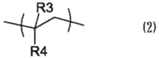
- wherein in general formula (2): R3 represents a hydrogen atom or a methyl group; R4 represents a phenyl group, a cyclohexadienyl group, a cyclohexenyl group or a cyclohexyl group which may have at least one substituent selected from the group consisting of a hydrocarbon group having 1 to 4 carbon atoms, a hydroxyl group, an alkoxy group and a halogen atom; and in the case where a plurality of the structural units (b) exist, R3s and R4s respectively may be the same or different from each other.
- wherein in general formula (1): R1 represents a hydrogen atom or a methyl group; R2 represents a group having 1 to 16 carbon atoms which has a hydrocarbon group, which may have a hydroxyl group or an alkoxy group; and in the case where a plurality of the structural units (a) exist, R1s and R2s respectively may be the same or different from each other,
- <4> The headmount display member according to item <3>, wherein in general formula (1), R1 and R2 represent a methyl group, and wherein in general formula (2): R3 represents a hydrogen atom; and R4 represents a cyclohexyl group which does not have a substituent.
- <5> The headmount display member according to item <3> or <4>, wherein the ratio of the structural unit (a) to the total of the structural units (a) and (b) is 30 to 80 mol%.
- <6> The headmount display member according to any one of items <1> to <5>, wherein the dimensional change rate at the time of water absorption in the case of a 3mmt injection-molded product is 0.2% or less.
- <7> The headmount display member according to any one of items <1> to <6>, wherein the resin composition contains an antioxidant and a mold release agent.
- <8> An optical lens comprising the headmount display member according to any one of items <1> to <7>.
- <9> A molded article comprising the headmount display member according to any one of items <1> to <7>.
- <10> A laminate having at least one vapor deposition layer on the surface of the molded article according to item <9>.
- <11> A half mirror comprising the laminate according to item <10>.
- <12> A light guide body comprising the laminate according to item <10>.
- According to a preferred aspect of the present invention, it is possible to provide a headmount display member, by which high-precision images can be viewed without distortion because of low birefringence, and by which deterioration of image quality due to aging and use environment can be suppressed because of high heat resistance and low water absorption (small dimensional change).
- Hereinafter, the present invention will be described in detail. Note that the present invention is not limited to the below-described embodiments, and can be arbitrarily changed and then carried out within a range in which the effects of the present invention are exerted.
- One embodiment of the present invention is a headmount display member which comprises a resin composition having a glass transition temperature (Tg) of 115°C or higher, wherein the saturated water absorption rate in the case of a 3mmt injection-molded product is 1.0% or less, and wherein the in-plane phase difference in the case of a 3mmt injection-molded product is 10 nm or less.
- In a preferred embodiment of the present invention, the resin composition contains a vinyl copolymer resin (A) which comprises a (meth)acrylic acid ester structural unit (a) represented by general formula (1) and a structural unit (b) represented by general formula (2).

- In general formula (1): R1 represents a hydrogen atom or a methyl group; R2 represents a group having 1 to 16 carbon atoms which has a hydrocarbon group, which may have a hydroxyl group or an alkoxy group; and in the case where a plurality of the structural units (a) exist, R1s and R2s respectively may be the same or different from each other.

- In general formula (2): R3 represents a hydrogen atom or a methyl group; R4 represents a phenyl group, a cyclohexadienyl group, a cyclohexenyl group or a cyclohexyl group which may have at least one substituent selected from the group consisting of a hydrocarbon group having 1 to 4 carbon atoms, a hydroxyl group, an alkoxy group and a halogen atom; and in the case where a plurality of the structural units (b) exist, R3s and R4s respectively may be the same or different from each other.
- In the present invention, an aspect in which: in general formula (1), R1 and R2 represent a methyl group; and in general formula (2), R3 represents a hydrogen atom and R4 represents a cyclohexyl group which does not have any substituent is particularly preferred.
- In this regard, "(meth)acrylic acid" indicates "methacrylic acid and/or acrylic acid".
- The structural unit (a) is a structural unit derived from a (meth)acrylic acid ester monomer which will be described later, and R1 is a hydrogen atom or a methyl group. Further, R2 is a group having 1 to 16 carbon atoms which has a hydrocarbon group, which may have a hydroxyl group or an alkoxy group. Specific examples thereof include: an alkyl group such as a methyl group, an ethyl group, a butyl group, a lauryl group, a stearyl group, a cyclohexyl group, and an isobornyl group; a hydroxyalkyl group such as a 2-hydroxyethyl group, a 2-hydroxypropyl group, and a 2-hydroxy-2-methylpropyl group; an alkoxyalkyl group such as a 2-methoxyethyl group and a 2-ethoxyethyl group; and an aryl group such as a benzyl group and a phenyl group. In the vinyl copolymer resin (A), R1s and R2s respectively may be the same or different from each other.
- As the structural unit (a), a (meth)acrylic acid ester structural unit in which R2 is a methyl group and/or an ethyl group is preferred, and a methyl methacrylate structural unit in which R1 is a methyl group and R2 is methyl group is more preferred.
- The structural unit (b) is represented by general formula (2) above. The structural unit (b), in which R4 is a group having a 6-membered ring other than the phenyl group, is obtained by the method for producing the vinyl copolymer resin (A) which will be described later, in which a (meth)acrylic acid ester monomer is copolymerized with an aromatic vinyl monomer which will be described later, and then the benzene ring in the aromatic vinyl monomer is hydrogenated to produce the vinyl copolymer resin (A). In the case where the benzene ring is hydrogenated, the benzene ring becomes a cyclohexyl group when the hydrogenation completely proceeds, and the benzene ring becomes a cyclohexenyl group or a cyclohexadienyl group when the hydrogenation partially proceeds. Further, it is considered that there is a case where hydrogenation is not caused and the benzene ring, i.e., the phenyl group remains. Examples of the hydrocarbon group having 1 to 4 carbon atoms include a methyl group, an ethyl group, a propyl group, an isopropyl group, a butyl group, an isobutyl group, and a tert-butyl group. The alkoxy group usually has 1 to 14 carbon atoms, and specific examples thereof include a methoxy group, an ethoxy group, a propoxy group, an isopropoxy group, a butoxy group, an isobutoxy group, and a tert-butoxy group. Examples of the halogen atom include F, Cl, Br, and I. The vinyl copolymer resin (A) usually has a plurality of structural units (b), and in this case, R3s and R4s respectively may be the same or different from each other.
- Further, the structural unit (b) may be a structural unit derived from an aliphatic vinyl monomer which will be described later. That is, in the case where a (meth)acrylic acid ester monomer is copolymerized with an aliphatic vinyl monomer to produce the vinyl copolymer resin (A) as described later, the structural unit (b) is a structural unit derived from the aliphatic vinyl monomer.
- In the vinyl copolymer resin (A), the ratio of hydrogenation of the benzene ring in the structural unit (b) is preferably 80% or more. When the ratio of hydrogenation is less than 80%, the transparency may be reduced. The ratio is more preferably 90% or more, and even more preferably 95% or more. The case where the ratio of hydrogenation of the benzene ring in the structural unit (b) is 80% or more means that the ratio of the number of R4s that are a cyclohexadienyl group, a cyclohexenyl group or a cyclohexyl group which may have a substituent to the number of all R4s in the structural units (b) is 80% or more. The case where the ratio of the number is 80% or more means that, for example, when 100 structural units (b) exist, 80 or more of 100 R4s are a cyclohexadienyl group, a cyclohexenyl group or a cyclohexyl group.
- The ratio of hydrogenation can be obtained based on the decrease ratio of the absorbance at 260 nm in the UV spectrum measurement of the resin before and after hydrogenation reaction (corresponding to absorption of the benzene ring).
- The vinyl copolymer resin (A) is mainly composed of the structural unit (a) and the structural unit (b). The ratio of the structural unit (a) is preferably 30 to 80 mol%, more preferably 50 to 80 mol%, and particularly preferably 63 to 75 relative to the total of the structural unit (a) and the structural unit (b). When the ratio of the structural unit (a) relative to the total of the structural unit (a) and the structural unit (b) is less than 30 mol%, the surface hardness may be reduced and the adhesion to a hard coat paint may be reduced, and it is not practical. Meanwhile, when the ratio is more than 80 mol%, under high-temperature and high-humidity conditions, a crack and haze may be caused in a vapor deposition layer and the size and optical properties may change, and it is not practical.
- The vinyl copolymer resin (A) is not particularly limited, and preferred are one obtained by copolymerizing a (meth)acrylic acid ester monomer with an aromatic vinyl monomer, followed by hydrogenation of an aromatic double bond derived from the aromatic vinyl monomer, and one obtained by copolymerizing a (meth)acrylic acid ester monomer with an aliphatic vinyl monomer. The former is particularly preferred.
- The (meth)acrylic acid ester monomer to be used in this case preferably has 4 to 20 carbon atoms. The (meth)acrylic acid ester monomer having 4 to 20 carbon atoms is not particularly limited, and specific examples thereof include methyl (meth)acrylate, ethyl (meth)acrylate, butyl (meth)acrylate, lauryl (meth)acrylate, stearyl (meth)acrylate, cyclohexyl (meth)acrylate, isobornyl (meth)acrylate, (2-hydroxyethyl) (meth)acrylate, (2-hydroxypropyl) (meth)acrylate, (2-hydroxy-2-methylpropyl) (meth)acrylate, (2-methoxyethyl) (meth)acrylate, (2-ethoxyethyl) (meth)acrylate, benzyl (meth)acrylate, phenyl (meth)acrylate, and 2-(meth)acryloyloxyethyl phosphorylcholine. Among them, methyl methacrylate is preferred.
- Specific examples of the aromatic vinyl monomer include styrene, α-methylstyrene, o-methylstyrene, p-hydroxystyrene, alkoxystyrene, chlorostyrene, and derivatives thereof. Among them, styrene and α-methylstyrene are preferred.
- Specific examples of the aliphatic vinyl monomer include vinylcyclohexane, isopropenylcyclohexane, and 1-isopropenyl-2-methylcyclohexane. Among them, vinylcyclohexane is preferred.
- Hereinafter, the method for hydrogenation of an aromatic double bond derived from the aromatic vinyl monomer after copolymerizing the (meth)acrylic acid ester monomer with the aromatic vinyl monomer will be described. For polymerizing the (meth)acrylic acid ester monomer and the aromatic vinyl monomer, a publicly-known method can be used, and for example, by a bulk polymerization method, a suspension polymerization method or a solution polymerization method, the vinyl copolymer resin (A) can be produced. The solution polymerization method is carried out, for example, by a method of continuously supplying a monomer composition containing monomers, a chain transfer agent and a polymerization initiator to a complete mixing tank to perform continuous polymerization at 100 to 180°C.
- Examples of the solvent to be used in this case include a hydrocarbon-based solvent such as toluene, xylene, cyclohexane, and methylcyclohexane; an ester-based solvent such as ethyl acetate and methyl isobutyrate; a ketone-based solvent such as acetone and methyl ethyl ketone; an ether-based solvent such as tetrahydrofuran and dioxane; and an alcohol-based solvent such as methanol and isopropanol.
- The hydrogenation reaction of the aromatic double bond after the polymerization of the (meth)acrylic acid ester monomer and the aromatic vinyl monomer is preferably performed in a solvent. The solvent to be used in the hydrogenation reaction may be the same as or different from the aforementioned polymerization solvent. Examples thereof include a hydrocarbon-based solvent such as cyclohexane and methylcyclohexane; an ester-based solvent such as ethyl acetate and methyl isobutyrate; a ketone-based solvent such as acetone and methyl ethyl ketone; an ether-based solvent such as tetrahydrofuran and dioxane; and an alcohol-based solvent such as methanol and isopropanol.
- The method for hydrogenation is not particularly limited, and a publicly-known method can be used. For example, hydrogenation can be performed at a hydrogen pressure of 3 to 30 MPa and a reaction temperature of 60 to 250°C by means of a batch type or continuous flow-type reaction. When the temperature is set to 60°C or higher, the reaction time is not too long, and when the temperature is set to 250°C or lower, cut of a molecular chain and hydrogenation of an ester moiety are hardly caused.
- Examples of the catalyst to be used in the hydrogenation reaction include a solid catalyst in which a metal such as nickel, palladium, platinum, cobalt, ruthenium and rhodium, or an oxide, salt or complex of the metal is carried by a porous carrier such as carbon, alumina, silica, silica-alumina, zirconia and diatomaceous earth.
- Further, the polymerization of the (meth)acrylic acid ester monomer and the aliphatic vinyl monomer can be carried out by publicly-known methods, for example, the methods described in
Japanese Laid-Open Patent Publication No. S63-3011 Japanese Laid-Open Patent Publication No. S63-170475 - In the present invention, the resin composition containing the vinyl copolymer resin (A) may contain another resin as long as transparency of the product is not impaired. Examples of said another resin that may be contained in the resin composition include methyl methacrylate/styrene copolymer resin, methyl methacrylate/styrene/maleic anhydride copolymer resin, styrene/methacrylic acid copolymer resin, styrene/maleic anhydride copolymer resin, poly(methyl methacrylate), polystyrene, norbornene-based resin, and polycarbonate.
- To the vinyl copolymer resin (A), an additive such as an antioxidant, a processing stabilizer, a light stabilizer, a heavy metal deactivator, a flame retardant, a lubricant, an antistatic agent, a surfactant, an antimicrobial agent, a mold release agent, an ultraviolet absorber, a plasticizer, and a compatibilizer may be added within a range in which the characteristics of the present invention are not impaired. The mixing method is not particularly limited, and it is possible to use a method of compounding the total amount of the additives, a method of dry-blending a master batch, a method of dry-blending the total amount of the additives, or the like.
- Examples of the antioxidant include triethylene glycol-bis[3-(3-tert-butyl-5-methyl-4-hydroxyphenyl)propionate], 1,6-hexanediol-bis[3-(3,5-di-tert-butyl-4-hydroxyphenyl)propionate], pentaerythritol-tetrakis[3-(3,5-di-tert-butyl-4-hydroxyphenyl)propionate], octadecyl-3-(3,5-di-tert-butyl-4-hydroxyphenyl)propionate, 1,3,5-trimethyl-2,4,6-tris(3,5-di-tert-butyl-4-hydroxybenzyl)benzene, N,N-hexamethylene bis(3,5-di-tert-butyl-4-hydroxy-hydrocinnamide), 3,5-di-tert-butyl-4-hydroxy-benzylphosphonate-diethyl ester, tris(3,5-di-tert-butyl-4-hydroxybenzyl) isocyanurate, and 3,9-bis{1,1-dimethyl-2-[β-(3-tert-butyl-4-hydroxy-5-methylphenyl)propionyloxy]ethyl}-2,4,8,10-tetraoxaspiro(5,5)undecane. The content of the antioxidant is preferably 0.001 to 0.3 parts by weight relative to 100 parts by weight of the vinyl copolymer resin (A).
- Examples of the processing stabilizer include a phosphorus-based processing heat stabilizer and a sulfur-based processing heat stabilizer. Examples of the phosphorus-based processing heat stabilizer include phosphorous acid, phosphoric acid, phosphonous acid, phosphonic acid, and esters thereof. Specific examples thereof include triphenyl phosphite, tris(nonylphenyl) phosphite, tris(2,4-di-tert-butylphenyl) phosphite, tris(2,6-di-tert-butylphenyl) phosphite, tridecyl phosphite, trioctyl phosphite, trioctadecyl phosphite, didecylmonophenyl phosphite, dioctylmonophenyl phosphite, diisopropylmonophenyl phosphite, monobutyldiphenyl phosphite, monodecyldiphenyl phosphite, monooctyldiphenyl phosphite, bis(2,6-di-tert-butyl-4-methylphenyl) pentaerythritol diphosphite, 2,2-methylenebis(4,6-di-tert-butylphenyl) octylphosphite, bis(nonylphenyl) pentaerythritol diphosphite, bis(2,4-dicumylphenyl) pentaerythritol diphosphite, bis(2,4-di-tert-butylphenyl) pentaerythritol diphosphite, distearylpentaerythritol diphosphite, tributyl phosphate, triethyl phosphate, trimethyl phosphate, triphenyl phosphate, diphenyl monoorthoxenyl phosphate, dibutyl phosphate, dioctyl phosphate, diisopropyl phosphate, dimethyl benzenephosphonate, diethyl benzenephosphonate, dipropyl benzenephosphonate, tetrakis(2,4-di-tert-butylphenyl)-4,4'-biphenylene diphosphonate, tetrakis(2,4-di-tert-butylphenyl)-4,3'-biphenylene diphosphonate, tetrakis(2,4-di-tert-butylphenyl)-3,3'-biphenylene diphosphonate, bis(2,4-di-tert-butylphenyl)-4-phenyl-phenylphosphonate, and bis(2,4-di-tert-butylphenyl)-3-phenyl-phenylphosphonate. The content of the phosphorus-based processing heat stabilizer is preferably 0.001 to 0.2 parts by weight relative to 100 parts by weight of the vinyl copolymer resin (A).
- Examples of the sulfur-based processing heat stabilizer include pentaerythritoltetrakis(3-lauryl thiopropionate), pentaerythritol-tetrakis(3-myristyl thiopropionate), pentaerythritol-tetrakis(3-stearyl thiopropionate), dilauryl-3,3'-thiodipropionate, dimyristyl-3,3'-thiodipropionate, and distearyl-3,3'-thiodipropionate. The content of the sulfur-based processing heat stabilizer is preferably 0.001 to 0.2 parts by weight relative to 100 parts by weight of the vinyl copolymer resin (A).
- Regarding the mold release agent, it is preferred that 90% by weight or more of it is made of an ester of an alcohol and a fatty acid. Specific examples of the ester of an alcohol and a fatty acid include an ester of a monohydric alcohol and a fatty acid and a partial ester or whole ester of a polyhydric alcohol and a fatty acid. As the above-described ester of a monohydric alcohol and a fatty acid, an ester of a monohydric alcohol having 1 to 20 carbon atoms and a saturated fatty acid having 10 to 30 carbon atoms is preferred. Further, as the partial ester or whole ester of a polyhydric alcohol and a fatty acid, a partial ester or whole ester of a polyhydric alcohol having 1 to 25 carbon atoms and a saturated fatty acid having 10 to 30 carbon atoms is preferred.
- Specific examples of the ester of a monohydric alcohol and a saturated fatty acid include stearyl stearate, palmityl palmitate, butyl stearate, methyl laurate, and isopropyl palmitate. Specific examples of the partial ester or whole ester of a polyhydric alcohol and a saturated fatty acid include whole esters or partial esters of monoglyceride stearate, diglyceride stearate, triglyceride stearate, monosorbitate stearate, monoglyceride behenate, monoglyceride caprate, monoglyceride laurate, pentaerythritol monostearate, pentaerythritol tetrastearate, pentaerythritol tetrapelargonate, propylene glycol monostearate, biphenyl biphenate, sorbitan monostearate, 2-ethylhexyl stearate and dipentaerythritols such as dipentaerythritol hexastearate. Among them, monoglyceride stearate and monoglyceride laurate are particularly preferred. The content of these mold release agents is preferably 0.005 to 2.0 parts by weight, more preferably 0.01 to 0.6 parts by weight, and even more preferably 0.02 to 0.5 parts by weight relative to 100 parts by weight of the vinyl copolymer resin (A).
- The ultraviolet absorber is preferably at least one ultraviolet absorber selected from the group consisting of a benzotriazole-based ultraviolet absorber, a benzophenone-based ultraviolet absorber, a triazine-based ultraviolet absorber, a cyclic iminoester-based ultraviolet absorber and a cyanoacrylate-based ultraviolet absorber. That is, ultraviolet absorbers mentioned below may be used solely, or two or more of them may be used in combination.
- Examples of the benzotriazole-based ultraviolet absorber include 2-(2-hydroxy-5-methylphenyl)benzotriazole, 2-(2-hydroxy-5-tert-octylphenyl)benzotriazole, 2-(2-hydroxy-3,5-dicumylphenyl)phenylbenzotriazole, 2-(2-hydroxy-3-tert-butyl-5-methylphenyl)-5-chlorobenzotriazole, 2,2'-methylenebis[4-(1,1,3,3-tetramethylbutyl)-6-(2N-benzotriazol-2-yl)phenol], 2-(2-hydroxy-3,5-di-tert-butylphenyl)benzotriazole, 2-(2-hydroxy-3,5-di-tert-butylphenyl)-5-chlorobenzotriazole, 2-(2-hydroxy-3,5-di-tert-amylphenyl)benzotriazole, 2-(2-hydroxy-5-tert-octylphenyl)benzotriazole, 2-(2-hydroxy-5-tert-butylphenyl)benzotriazole, 2-(2-hydroxy-4-octoxyphenyl)benzotriazole, 2,2'-methylenebis(4-cumyl-6-benzotriazolephenyl), 2,2'-p-phenylenebis(1,3-benzoxazin-4-one), and 2-[2-hydroxy-3-(3,4,5,6-tetrahydrophthalimidomethyl)-5-methylphenyl]benzotriazole.
- Examples of the benzophenone-based ultraviolet absorber include 2,4-dihydroxybenzophenone, 2-hydroxy-4-methoxybenzophenone, 2-hydroxy-4-octoxybenzophenone, 2-hydroxy-4-benzyloxybenzophenone, 2-hydroxy-4-methoxy-5-sulfoxybenzophenone, 2-hydroxy-4-methoxy-5-sulfoxytrihydrate benzophenone, 2,2'-dihydroxy-4-methoxybenzophenone, 2,2',4,4'-tetrahydroxybenzophenone, 2,2'-dihydroxy-4,4'-dimethoxybenzophenone, 2,2'-dihydroxy-4,4'-dimethoxy-5-sodiumsulfoxybenzophenone, bis(5-benzoyl-4-hydroxy-2-methoxyphenyl)methane, 2-hydroxy-4-n-dodecyloxybenzophonone, and 2-hydroxy-4-methoxy-2'-carboxybenzophenone.
- Examples of the triazine-based ultraviolet absorber include 2-(4,6-diphenyl-1,3,5-triazin-2-yl)-5-[(hexyl)oxy]-phenol and 2-(4,6-bis(2,4-dimethylphenyl)-1,3,5-triazin-2-yl)-5-[(octyl)oxy]-phenol.
- Examples of the cyclic iminoester-based ultraviolet absorber include 2,2'-bis(3,1-benzoxazin-4-one), 2,2'-p-phenylenebis(3,1-benzoxazin-4-one), 2,2'-m-phenylenebis(3,1-benzoxazin-4-one), 2,2'-(4,4'-diphenylene)bis(3,1-benzoxazin-4-one), 2,2'-(2,6-naphthalene)bis(3,1-benzoxazin-4-one), 2,2'-(1,5-naphthalene)bis(3,1-benzoxazin-4-one), 2,2' -(2-methyl-p-phenylene)bis(3,1 -benzoxazin-4-one), 2,2'-(2-nitro-p-phenylene)bis(3,1-benzoxazin-4-one), and 2,2'-(2-chloro-p-phenylene)bis(3,1-benzoxazin-4-one).
- Examples of the cyanoacrylate-based ultraviolet absorber include 1,3-bis-[(2'-cyano-3',3'-diphenylacryloyl)oxy]-2,2-bis[(2-cyano-3,3-diphenylacryloyl)oxy]methyl)propane and 1,3-bis-[(2-cyano-3,3-diphenylacryloyl)oxy]benzene.
- The content of the ultraviolet absorber is preferably 0.01 to 3.0 parts by weight, more preferably 0.02 to 1.0 parts by weight, and even more preferably 0.05 to 0.8 parts by weight relative to 100 parts by weight of the vinyl copolymer resin (A). When the content is within these ranges, sufficient weatherability can be imparted to the vinyl copolymer resin (A) according to intended use.
- The headmount display (hereinafter sometimes referred to as "HMD") member according to one embodiment of the present invention is a molded product which can be produced by melt-molding the above-described resin composition (preferably the resin composition containing the vinyl copolymer resin (A)), and refers to an optical member which transmits and/or separates light, characteristically polarized light.
- Hereinafter, characteristics of the HMD member according to one embodiment of the present invention will be described.
- Since the HMD member according to one embodiment of the present invention is made of the resin composition having a glass transition temperature of 115°C or higher, it is quite possible to place it around LED light sources used in recent optical projection apparatuses. Further, when it is made of the above-described resin composition also having thermal stability, it can be suitably used for applications where further high-temperature durability is required. The resin composition to be used in the present invention preferably has a glass transition temperature of 118 to 140°C, and more preferably has a glass transition temperature of 118 to 135°C.
- Regarding the HMD member according to one embodiment of the present invention, the saturated water absorption rate in the case of a 3mmt injection-molded product is 1.0% or less, preferably 0.9% or less, and more preferably 0.7% or less. The lower the value is, the better, but the lower limit is usually about 0.01%. In the present invention, the saturated water absorption rate can be measured by the method described in the Examples below.
- The HMD member according to one embodiment of the present invention is characterized in that the absolute value of in-plane direction phase difference (hereinafter also referred to as "in-plane phase difference") Re in the case of a 3mmt injection-molded product is 10 nm or less. The absolute value of in-plane direction phase difference Re is more preferably 7 nm or less, even more preferably 6 nm or less, and particularly preferably 5 nm or less.
- In general, the absolute value of in-plane direction phase difference Re is an index representing the magnitude of birefringence. The HMD member according to one embodiment of the present invention has a birefringence sufficiently smaller than those of products made of existing resins (e.g., PMMA, PC, cyclic olefin resin, etc.), and is suitable for applications where a low birefringence or zero birefringence is required as the HMD member.
- Meanwhile, when the absolute value of in-plane direction phase difference Re is more than 10 nm, it means that the refractive index anisotropy is high, and there is a case where it cannot be used as an HMD member for which low birefringence or zero birefringence is required.
- When the HMD member according to one embodiment of the present invention is a molded product molded into a film shape, the absolute value of photoelastic coefficient (CR) is preferably 10×10-12Pa-1 or less, more preferably 9.0×10⁻¹²Pa-1 or less, and even more preferably 8.0×10⁻¹²Pa-1 or less. When the value is within the above-described range, polarization disturbance due to external stress caused by, for example, the difference in linear expansion between the HMD optical member and a case supporting the member, is less likely to occur.
- In the present invention, the photoelastic coefficient (CR) is a physical coefficient represented by R=(C)×σ, wherein R is the phase difference observed when polarized light is applied to an object in which the magnitude and direction of the distortion S are changed by the addition of external force σ, and is a value specific to each transparent substance.
- The photoelastic coefficient is described in various documents (see, for example, Kagaku Sosetsu, No. 39, 1998 (published by Gakkai Publishing Center)), and is defined by formulae (i-a) and (i-b) below. It is understood that the closer to zero the value of photoelastic coefficient (CR) is, the smaller the change in birefringence due to external force is.


- The absolute value of photoelastic coefficient (CR) within the above-described range is sufficiently smaller than those of existing resins (e.g., PC, cyclic olefin resin, etc.). Accordingly, (photoelastic) birefringence caused by external force is not generated, and therefore the change in birefringence is smaller. Further, (photoelastic) birefringence caused by residual stress at the time of molding is not easily generated, and therefore the birefringence distribution in a molded article is also small.
- As described above, it is understood that the HMD member made of the resin composition according to the present invention has a saturated water absorption rate, in-plane phase difference Re and photoelastic coefficient C which are sufficiently smaller (approximately zero) when compared to HMD members made of existing resins.
- Regarding the HMD member of the present invention, the dimensional change rate at the time of water absorption in the case of a 3mmt injection-molded product is preferably 0.2% or less, more preferably 0.12% or less, and particularly preferably 0.10% or less. In the present invention, the dimensional change rate at the time of water absorption can be measured by the method described in the Examples below.
- The HMD member can be produced by melt-molding the resin composition according to the present invention. As the melt-molding method, a melt hot pressing method, an injection molding method or the like can be used. From the viewpoint of productivity, the injection molding method is preferred. Further, it is also possible to continuously extrude the resin composition into a plate-like shape by means of a melt extrusion method and then form the surface into a prism shape by means of the melt hot pressing method.
- With respect to forming the surface, it does not matter whether the surface has a regular periodic structure or a structure without any particular regularity. In the case of having a regular periodic structure, one period of the periodic structure is preferably 10 to 500 µm. When the periodic structure is 10 µm or more, light can be controlled as rays.
- A molded article obtained by melt-molding in this way may be directly used as the HMD member or may be processed as described below to be used as the HMD member.
- The HMD member according to one embodiment of the present invention may be subjected to a dielectric vapor deposition treatment, an anti-reflection treatment, a metal vapor deposition treatment, a hard coat treatment, an anchor coat treatment, a transparent conductive treatment, etc. according to need.
- These treatments can be carried out, for example, by vapor-depositing an inorganic compound or a metal compound on the surface of the molded article according to one embodiment of the present invention to provide an inorganic layer or a metal vapor deposition layer. Note that the inorganic layer is preferably a multilayer transparent dielectric film.
- According to need, to the surface of the HMD member according to one embodiment of the present invention, a multilayer transparent dielectric film can be provided by vapor-depositing an inorganic compound selected from among a metal oxide, a silicon oxide, a metal fluoride, a metal sulfide and a mixture thereof to form one to multiple layers. Specific examples of the metal oxide include titanium oxide, aluminum oxide, zirconium oxide, cerium oxide, bismuth oxide, chromium oxide, iron oxide, hafnium oxide, thallium oxide, tantalum pentoxide, iridium oxide, tungsten oxide, molybdenum oxide, lanthanum oxide, magnesium oxide, samarium oxide, antimony oxide, scandium oxide, tin oxide, yttrium oxide, europium oxide, and zinc oxide. Specific examples of the metal fluoride include aluminum fluoride, magnesium fluoride, barium fluoride, cerium fluoride, calcium fluoride, lanthanum fluoride, lithium fluoride, neodymium fluoride, sodium fluoride, lead fluoride, strontium fluoride, cryolite, and chiolite. Specific examples of the metal sulfide include zinc sulfide and rhodium sulfide.
- The thickness of the multilayer transparent dielectric film is not particularly limited, but from the viewpoint of adhesion between the member surface and the dielectric thin film, it is preferably 10 to 500 nm as a whole.
- The method for forming the multilayer transparent dielectric film is not particularly limited, and a publicly-known method can be used. Examples thereof include a vacuum deposition method, an ion plating method, a sputtering method, an ion beam-assisted method, and a plasma-assisted method. In the case where the optical thin film is a laminated film consisting of a plurality of layers, the film may be formed by combining these methods. Among them, the vacuum deposition method in which a film raw material is heated by an electron gun is widely used in terms of reproducibility and controllability of optical characteristics and production efficiency. In the case of the vacuum deposition method using electron gun heating, it is preferable to prevent reflection electrons from hitting the substrate in order to improve the adhesion between the molded article and the multilayer dielectric thin film. The method for preventing reflection electrons from hitting the substrate is not particularly limited, and a publicly-known method, for example, the methods described in
Japanese Patent No. 5280149 Japanese Laid-Open Patent Publication No. 2003-193221 - The multilayer transparent dielectric film may be directly formed on the member surface, or may be formed after performing a surface treatment by means of applying a hard coat agent, an antistatic treatment, etc., and according to need, it is possible to perform a treatment by means of corona discharge or plasma discharge, and a surface treatment by means of applying a primer agent having an epoxy group, an isocyanate group or the like to improve the adhesion to the multilayer transparent dielectric film.
- Further, for the purpose of imparting functions such as water repellency and antifouling property, a thin film may be formed on the multilayer transparent dielectric film.
- According to need, to the surface of the HMD member according to one embodiment of the present invention, a metal vapor deposition layer may be provided by vapor-depositing a metal compound such as zinc oxide and indium tin oxide to form one to multiple layers.
- As in the case of the formation of the multilayer transparent dielectric film, as the method for forming the metal vapor deposition layer, any conventionally known technique such as a vacuum deposition method, a sputtering method and an ion plating method can be used.
- The thickness of the metal vapor deposition layer is not particularly limited and can be suitably selected, for example, within a range of 5 nm to 1000 nm, according to the application.
- The number of layers of the metal vapor deposition layer is not particularly limited and can be suitably selected according to the application. Further, as in the case of the formation of the multilayer transparent dielectric film, according to need, it is possible to perform a treatment by means of corona discharge or plasma discharge, and a surface treatment by means of applying a primer agent to improve the adhesion to the metal vapor deposition layer.
- In the present invention, a molded article having, on the surface thereof, an inorganic layer (e.g., a multilayer transparent dielectric film) and a metal vapor deposition layer (e.g., aluminum, tin, and silver) like those described above, is also referred to as a "laminate".
- Examples of the optical lens according to one embodiment of the present invention include a convex lens, a Fresnel lens, an aspheric lens, an inner lens, a gradient index lens, and the microlens array described in International Publication
WO2013/175549 pamphlet. - The thickness of the optical lens according to one embodiment of the present invention is not particularly limited, and can be suitably selected, for example, within a range where the optical path length is 10 to 100000 µm, according to the application.
- The optical lens according to one embodiment of the present invention can be produced according to a publicly-known production method, except that the above-described resin composition is used as a material.
- The half mirror according to one embodiment of the present invention is characterized in that it includes the above-described laminate, and can be used as a member constituting a headmount display.
- As the aforementioned laminate included in the half mirror according to one embodiment of the present invention, one having a multilayer transparent dielectric film and a metal thin film, which are suitably selected according to the application of the half mirror, can be used.
- Further, the thickness of the half mirror according to one embodiment of the present invention can be suitably selected within a range where the optical path length is 10 to 100000 µm according to the application.
- The method for producing the half mirror according to one embodiment of the present invention is not particularly limited, except that the above-described laminate is included, and the half mirror can be produced according to a publicly-known production method.
- The half mirror according to one embodiment of the present invention includes the above-described laminate of the present invention, and therefore has high optical isotropy (low birefringence) and is excellent in heat resistance, color tone, surface hardness, durability under use environment, and inorganic adhesion.
- The light guide body according to one embodiment of the present invention is characterized in that it includes the above-described laminate, and can be used as a member constituting a headmount display.
- The light guide body according to one embodiment of the present invention includes any of a plurality of types such as a prism type, a planar type and a wedge substrate type, but the prism type is particularly suitable. A prism-type light guide body is composed of two prisms, and a multilayer transparent dielectric film and a metal thin film are formed on the overlapping surfaces that are joined to each other. That is, the above-described laminate can be used as a prism having a multilayer transparent dielectric film and a metal thin film.
- The size of the light guide body according to one embodiment of the present invention is not particularly limited and it may be designed within a range where the optical path length is 10 to 100000 µm.
- The method for producing the light guide body according to one embodiment of the present invention is not particularly limited, except that the above-described laminate is included, and the light guide body can be produced according to a publicly-known production method.
- The light guide body according to one embodiment of the present invention includes the above-described laminate of the present invention, and therefore has high optical isotropy (low birefringence) and is excellent in heat resistance, color tone, surface hardness, durability under use environment, and inorganic adhesion.
- Hereinafter, the present invention will be specifically described by way of examples, but the present invention is not limited thereto.
- Using a DSC7000X-type differential scanning calorimeter manufactured by Hitachi High-Tech Science Corporation, the measurement was carried out with 5 mg of a resin and nitrogen gas being flowed at 30 ml/min at a temperature raising rate of 10°C/min, and calculation was made according to a midpoint method.
- Using an injection molding machine (manufactured by FANUC Corporation, FANUC ROBOSHOT α-S30iA), a resin material was molded into a circular plate (diameter: 40 mm, thickness: 3 mm). The resin material used was dried at 100°C for 8 hours or more in advance. The cylinder temperature of the injection molding machine was set to 230 to 240°C, the mold temperature was set to a temperature 15°C lower than Tg, and the cooling time was 15 seconds. The saturated water absorption rate of the obtained circular plate was measured in accordance with Method A of JIS-K-7209. Specifically, the circular plate was dried using a dryer whose temperature was adjusted to 50°C until the mass of the circular plate became constant, and after that, the circular plate was immersed in distilled water (23°C) in a container and taken out therefrom at predetermined time intervals, and after the moisture on the surface was wiped off, the measurement of the mass was carried out.
- <Method for Measuring In-Plane Phase Difference (nm)>
- A circular plate (diameter: 40 mm, thickness: 3 mm) obtained by molding in the same manner as above was subjected to the measurement using a two-dimensional birefringence evaluation apparatus WPA-200 manufactured by Ryokosha Co., Ltd.
- Regarding a cast film having a thickness of 0.1 mm obtained by forming the resin material, change in birefringence relative to change in load at a wavelength of 633 nm was measured using an ellipsometer M-220 manufactured by JASCO Corporation and calculation was made. Regarding the cast film, a resin solution obtained by dissolving the resin material (5 wt%) in an organic solvent (dichloromethane, etc.) was poured into a smoothly polished SUS formwork, the solvent was evaporated over 12 hours or more, and then drying was further performed at 100°C for 4 hours or more, thereby preparing the cast film.
- A water absorption test was carried out in a manner similar to that for the saturated water absorption rate, and a circular plate was taken out from water over time, the size was measured using a micrometer, and calculation was made. Regarding the size, two diameters, which are one in the direction of resin flow at the time of injection molding and the other in the direction perpendicular thereto, were measured, and the average value of the diameters was adopted.
- A copolymer resin (A1') consisting of 75 mol% of methyl methacrylate and 25 mol% of styrene was dissolved in methyl isobutyrate to prepare a 10 wt% solution of methyl isobutyrate. To a 1000-mL autoclave, 500 parts by weight of the 10 wt% solution of methyl isobutyrate containing (A1') and 1 part by weight of 10 wt% Pd/C were fed, and the mixture was held under a hydrogen pressure of 9 MPa at 200°C for 15 hours, thereby hydrogenating a benzene ring moiety. The catalyst was removed using a filter, and the filtrate was introduced into a solvent-removing apparatus, thereby obtaining a vinyl copolymer resin (A1) in a pellet form. According to the 1H-NMR measurement, the ratio of the methyl methacrylate structural unit was 75 mol%, and according to the measurement of absorbance at a wavelength of 260 nm, the hydrogenation rate of the benzene ring moiety was 99%.
- A vinyl copolymer resin (A2) was obtained in a manner similar to that in Synthesis Example 1, except that a copolymer resin (A2') consisting of 63 mol% of methyl methacrylate and 37 mol% of styrene was used instead of (A1') used in Synthesis Example 1. According to the 1H-NMR measurement, the ratio of the methyl methacrylate structural unit was 63 mol%, and according to the measurement of absorbance at a wavelength of 260 nm, the hydrogenation rate of the benzene ring moiety was 99%.
- A vinyl copolymer resin (A3) was obtained in a manner similar to that in Synthesis Example 1, except that a copolymer resin (A3') consisting of 50 mol% of methyl methacrylate and 50 mol% of styrene was used instead of (A1') used in Synthesis Example 1. According to the 1H-NMR measurement, the ratio of the methyl methacrylate structural unit was 50 mol%, and according to the measurement of absorbance at a wavelength of 260 nm, the hydrogenation rate of the benzene ring moiety was 99%.
- A vinyl copolymer resin (A4) was obtained in a manner similar to that in Synthesis Example 1, except that a copolymer resin (A4') consisting of 30 mol% of methyl methacrylate and 70 mol% of styrene was used instead of (A1') used in Synthesis Example 1. According to the 1H-NMR measurement, the ratio of the methyl methacrylate structural unit was 30 mol%, and according to the measurement of absorbance at a wavelength of 260 nm, the hydrogenation rate of the benzene ring moiety was 99%.
- The vinyl copolymer resin (A1) obtained in Synthesis Example 1 was injection-molded to prepare a 3mmt injection-molded product, and the saturated water absorption rate, the in-plane phase difference, and the dimensional change rate at the time of water absorption were measured. The measurement results thereof are shown in Table 1 below together with the measurement results of the glass transition temperature of the resin pellet obtained in Synthesis Example 1 and the photoelastic coefficient of the molded product molded into a film shape.
- Next, the vinyl copolymer resin (A1) obtained in Synthesis Example 1 was dried at 100°C for 8 hours or more using an air-blowing constant-temperature dryer DRM420DD manufactured by ADVANTEC, and then injection-molded by an injection molding machine S-2000i30A manufactured by FANUC at a cylinder temperature of 235°C and at a mold temperature that was 10°C lower than the glass transition temperature of the resin, thereby obtaining an optical lens having a diameter of 50 mm and a maximum thickness of 6 mm.
- An optical lens was prepared in a manner similar to that in Example 1, except that one of the vinyl copolymer resins (A2) to (A4) obtained in Synthesis Examples 2-4 was used instead of the vinyl copolymer resin (A1) obtained in Synthesis Example 1. The measurement results of the values of physical properties are shown in Table 1.
- An optical lens was prepared in a manner similar to that in Example 1, except that a resin obtained by nuclear hydrogenation of polystyrene was used instead of the vinyl copolymer resin (A1) obtained in Synthesis Example 1. The measurement results of the values of physical properties are shown in Table 1.
- An optical lens was prepared in a manner similar to that in Example 1, except that polymethyl methacrylate (PMMA) was used instead of the vinyl copolymer resin (A1) obtained in Synthesis Example 1. The measurement results of the values of physical properties are shown in Table 1.
Table 1 Composition of resin before nuclear hydrogenation MMA/St (molar ratio) Tg (°C) Saturated water absorption rate (%) In-plane phase difference (nm) Photoelastic coefficient (x10-12Pa-1) Dimensional change rate at time of water absorption (%) Synthetic judgment Example 1 75/25 120 0.9 4 -5 0.11 ○ Example 2 63/37 120 0.5 2 -6 0.06 ○ Example 3 50/50 123 0.4 3 -7 0.05 ○ Example 4 30/70 129 0.3 5 -8 0.04 ○ Reference Example 1 0/100 136 0.01 10 -10 0.02 ○ Comparative Example 1 100/0 114 2 20 -4 0.40 ×
Claims (12)
- A headmount display member which comprises a resin composition having a glass transition temperature (Tg) of 115°C or higher, wherein a saturated water absorption rate in the case of a 3mmt injection-molded product is 1.0% or less, and wherein an in-plane phase difference in the case of a 3mmt injection-molded product is 10 nm or less.
- The headmount display member according to claim 1, wherein the resin composition has an absolute value of photoelastic coefficient of 10×10-12Pa-1 or less.
- The headmount display member according to claim 1 or 2, wherein the resin composition contains a vinyl copolymer resin (A) comprising a structural unit (a) represented by general formula (1) and a structural unit (b) represented by general formula (2):
 wherein in general formula (1): R1 represents a hydrogen atom or a methyl group; R2 represents a group having 1 to 16 carbon atoms which has a hydrocarbon group, which may have a hydroxyl group or an alkoxy group; and in the case where a plurality of the structural units (a) exist, R1s and R2s respectively may be the same or different from each other,
 wherein in general formula (2): R3 represents a hydrogen atom or a methyl group; R4 represents a phenyl group, a cyclohexadienyl group, a cyclohexenyl group or a cyclohexyl group which may have at least one substituent selected from the group consisting of a hydrocarbon group having 1 to 4 carbon atoms, a hydroxyl group, an alkoxy group and a halogen atom; and in the case where a plurality of the structural units (b) exist, R3s andR4s respectively may be the same or different from each other.
 - The headmount display member according to claim 3, wherein in general formula (1), R1 and R2 represent a methyl group, and wherein in general formula (2): R3 represents a hydrogen atom; and R4 represents a cyclohexyl group which does not have a substituent.
- The headmount display member according to claim 3 or 4, wherein a ratio of the structural unit (a) to the total of the structural units (a) and (b) is 30 to 80 mol%.
- The headmount display member according to any one of claims 1 to 5, wherein a dimensional change rate at the time of water absorption in the case of a 3mmt injection-molded product is 0.2% or less.
- The headmount display member according to any one of claims 1 to 6, wherein the resin composition comprises an antioxidant and a mold release agent.
- An optical lens comprising the headmount display member according to any one of claims 1 to 7.
- A molded article comprising the headmount display member according to any one of claims 1 to 7.
- A laminate having at least one vapor deposition layer on the surface of the molded article according to claim 9.
- A half mirror comprising the laminate according to claim 10.
- A light guide body comprising the laminate according to claim 10.
Applications Claiming Priority (2)
| Application Number | Priority Date | Filing Date | Title |
|---|---|---|---|
| JP2022014105 | 2022-02-01 | ||
| PCT/JP2023/001434 WO2023149216A1 (en) | 2022-02-01 | 2023-01-19 | Headmount display member and optical lens using same |
Publications (2)
| Publication Number | Publication Date |
|---|---|
| EP4474874A1 true EP4474874A1 (en) | 2024-12-11 |
| EP4474874A4 EP4474874A4 (en) | 2025-04-16 |
Family
ID=87552048
Family Applications (1)
| Application Number | Title | Priority Date | Filing Date |
|---|---|---|---|
| EP23749532.0A Pending EP4474874A4 (en) | 2022-02-01 | 2023-01-19 | HEAD SUPPORT DISPLAY ELEMENT AND OPTICAL LENS USING SAME |
Country Status (7)
| Country | Link |
|---|---|
| US (1) | US20250093655A1 (en) |
| EP (1) | EP4474874A4 (en) |
| JP (1) | JPWO2023149216A1 (en) |
| KR (1) | KR20240141236A (en) |
| CN (1) | CN118633044A (en) |
| TW (1) | TW202344865A (en) |
| WO (1) | WO2023149216A1 (en) |
Families Citing this family (3)
| Publication number | Priority date | Publication date | Assignee | Title |
|---|---|---|---|---|
| WO2025164478A1 (en) * | 2024-01-31 | 2025-08-07 | 三井化学株式会社 | Photocurable resin composition, cured product, optical molded product, and optical device |
| WO2025164479A1 (en) * | 2024-01-31 | 2025-08-07 | 三井化学株式会社 | Photocurable resin composition, optical molded product, and method for producing optical molded product |
| WO2025164476A1 (en) * | 2024-01-31 | 2025-08-07 | 三井化学株式会社 | Photocurable resin composition, optical molded product, optical device, and method for producing optical molded product |
Family Cites Families (13)
| Publication number | Priority date | Publication date | Assignee | Title |
|---|---|---|---|---|
| JPS633011A (en) | 1986-06-24 | 1988-01-08 | Hitachi Ltd | Transparent copolymer having low water-absorption |
| JPS63170475A (en) | 1987-01-07 | 1988-07-14 | Nissan Motor Co Ltd | Clear coating composition for topcoating |
| US6991763B2 (en) * | 2000-04-26 | 2006-01-31 | Rohm And Haas Company | Polymer process |
| JP2003193221A (en) | 2001-12-21 | 2003-07-09 | Ito Kogaku Kogyo Kk | Method of forming vacuum deposited film |
| JP5280149B2 (en) | 2008-10-28 | 2013-09-04 | 日本電子株式会社 | Vacuum deposition equipment |
| JP5837685B2 (en) | 2012-05-21 | 2015-12-24 | パイオニア株式会社 | Light source unit and head-up display |
| JP2014005335A (en) * | 2012-06-22 | 2014-01-16 | Mitsubishi Gas Chemical Co Inc | Transparent resin composition |
| WO2017135335A1 (en) * | 2016-02-05 | 2017-08-10 | 三菱瓦斯化学株式会社 | Stretched multilayer thermoplastic resin film |
| JP6674404B2 (en) * | 2016-03-29 | 2020-04-01 | 旭化成株式会社 | Methacrylic resin composition and molded article |
| US11333887B2 (en) | 2017-01-20 | 2022-05-17 | Sony Corporation | Optical device and display device |
| JP7129181B2 (en) * | 2017-03-17 | 2022-09-01 | 旭化成株式会社 | Parts for head-mounted displays |
| JP2020180994A (en) * | 2017-08-04 | 2020-11-05 | 三菱瓦斯化学株式会社 | Synthetic resin laminated stretch film |
| JP7405670B2 (en) * | 2020-03-30 | 2023-12-26 | 旭化成株式会社 | Resin light guide for head-mounted displays |
-
2023
- 2023-01-19 CN CN202380016463.4A patent/CN118633044A/en active Pending
- 2023-01-19 EP EP23749532.0A patent/EP4474874A4/en active Pending
- 2023-01-19 US US18/729,538 patent/US20250093655A1/en active Pending
- 2023-01-19 JP JP2023578461A patent/JPWO2023149216A1/ja active Pending
- 2023-01-19 KR KR1020247021660A patent/KR20240141236A/en active Pending
- 2023-01-19 WO PCT/JP2023/001434 patent/WO2023149216A1/en not_active Ceased
- 2023-01-19 TW TW112102735A patent/TW202344865A/en unknown
Also Published As
| Publication number | Publication date |
|---|---|
| CN118633044A (en) | 2024-09-10 |
| US20250093655A1 (en) | 2025-03-20 |
| EP4474874A4 (en) | 2025-04-16 |
| KR20240141236A (en) | 2024-09-26 |
| JPWO2023149216A1 (en) | 2023-08-10 |
| TW202344865A (en) | 2023-11-16 |
| WO2023149216A1 (en) | 2023-08-10 |
Similar Documents
| Publication | Publication Date | Title |
|---|---|---|
| JP7683643B2 (en) | Polycarbonate resin, its manufacturing method, and optical lens | |
| US20250093655A1 (en) | Headmount display member and optical lens using same | |
| EP3750939B1 (en) | Polycarbonate resin, production method therefor, and optical molded body | |
| JP6908026B2 (en) | A polycarbonate copolymer, an optical lens and a film using the same, and a method for producing the copolymer. | |
| EP3604440B1 (en) | Polycarbonate resin composition and optical lens using same | |
| CN108627979B (en) | Head-mounted display member | |
| TW202239811A (en) | Polycarbonate resin, method for producing the same, and optical lens | |
| JP6861569B2 (en) | Polycarbonate resin, its manufacturing method and optical molded product | |
| JP6918102B2 (en) | Polycarbonate resin lens and polycarbonate resin composition | |
| KR20240035915A (en) | Method for producing thermoplastic resin | |
| EP4442768A1 (en) | Polycarbonate resin composition and optical lens using same | |
| EP4455186B1 (en) | Polycarbonate resin, and method for producing same | |
| JP5038601B2 (en) | Polycarbonate resin composition and spectacle lens | |
| JP5808961B2 (en) | Polycarbonate copolymer for optical lens and optical lens comprising the polycarbonate | |
| TW201420657A (en) | Cellulose acylate film, polarizing plate using the same and liquid crystal display device | |
| JP2024102921A (en) | Thermoplastic resin composition and optical member using said resin composition | |
| EP4692165A1 (en) | Polycarbonate resin and molded article | |
| HK40000377A (en) | Polycarbonate copolymer, optical lens and film in which said polycarbonate copolymer is used, and method for producing said copolymer | |
| HK40000377B (en) | Polycarbonate copolymer, optical lens and film in which said polycarbonate copolymer is used, and method for producing said copolymer | |
| HK1213587B (en) | Polycarbonate resin, production method therefor, and optical molded body |
Legal Events
| Date | Code | Title | Description |
|---|---|---|---|
| STAA | Information on the status of an ep patent application or granted ep patent |
Free format text: STATUS: THE INTERNATIONAL PUBLICATION HAS BEEN MADE |
|
| PUAI | Public reference made under article 153(3) epc to a published international application that has entered the european phase |
Free format text: ORIGINAL CODE: 0009012 |
|
| STAA | Information on the status of an ep patent application or granted ep patent |
Free format text: STATUS: REQUEST FOR EXAMINATION WAS MADE |
|
| 17P | Request for examination filed |
Effective date: 20240719 |
|
| AK | Designated contracting states |
Kind code of ref document: A1 Designated state(s): AL AT BE BG CH CY CZ DE DK EE ES FI FR GB GR HR HU IE IS IT LI LT LU LV MC ME MK MT NL NO PL PT RO RS SE SI SK SM TR |
|
| REG | Reference to a national code |
Ref country code: DE Ref legal event code: R079 Free format text: PREVIOUS MAIN CLASS: G02B0005300000 Ipc: G02B0001040000 |
|
| A4 | Supplementary search report drawn up and despatched |
Effective date: 20250313 |
|
| RIC1 | Information provided on ipc code assigned before grant |
Ipc: G02B 1/04 20060101AFI20250307BHEP |
|
| DAV | Request for validation of the european patent (deleted) | ||
| DAX | Request for extension of the european patent (deleted) |