EP4474799A1 - Method for analyzing structure of solid-state electrolyte film - Google Patents
Method for analyzing structure of solid-state electrolyte film Download PDFInfo
- Publication number
- EP4474799A1 EP4474799A1 EP24760610.6A EP24760610A EP4474799A1 EP 4474799 A1 EP4474799 A1 EP 4474799A1 EP 24760610 A EP24760610 A EP 24760610A EP 4474799 A1 EP4474799 A1 EP 4474799A1
- Authority
- EP
- European Patent Office
- Prior art keywords
- solid electrolyte
- electrolyte film
- binder
- analyzing
- film structure
- Prior art date
- Legal status (The legal status is an assumption and is not a legal conclusion. Google has not performed a legal analysis and makes no representation as to the accuracy of the status listed.)
- Pending
Links
Images





Classifications
-
- G—PHYSICS
- G01—MEASURING; TESTING
- G01N—INVESTIGATING OR ANALYSING MATERIALS BY DETERMINING THEIR CHEMICAL OR PHYSICAL PROPERTIES
- G01N23/00—Investigating or analysing materials by the use of wave or particle radiation, e.g. X-rays or neutrons, not covered by groups G01N3/00 – G01N17/00, G01N21/00 or G01N22/00
- G01N23/22—Investigating or analysing materials by the use of wave or particle radiation, e.g. X-rays or neutrons, not covered by groups G01N3/00 – G01N17/00, G01N21/00 or G01N22/00 by measuring secondary emission from the material
- G01N23/2202—Preparing specimens therefor
-
- G—PHYSICS
- G01—MEASURING; TESTING
- G01N—INVESTIGATING OR ANALYSING MATERIALS BY DETERMINING THEIR CHEMICAL OR PHYSICAL PROPERTIES
- G01N1/00—Sampling; Preparing specimens for investigation
- G01N1/28—Preparing specimens for investigation including physical details of (bio-)chemical methods covered elsewhere, e.g. G01N33/50, C12Q
-
- G—PHYSICS
- G01—MEASURING; TESTING
- G01N—INVESTIGATING OR ANALYSING MATERIALS BY DETERMINING THEIR CHEMICAL OR PHYSICAL PROPERTIES
- G01N23/00—Investigating or analysing materials by the use of wave or particle radiation, e.g. X-rays or neutrons, not covered by groups G01N3/00 – G01N17/00, G01N21/00 or G01N22/00
- G01N23/22—Investigating or analysing materials by the use of wave or particle radiation, e.g. X-rays or neutrons, not covered by groups G01N3/00 – G01N17/00, G01N21/00 or G01N22/00 by measuring secondary emission from the material
- G01N23/225—Investigating or analysing materials by the use of wave or particle radiation, e.g. X-rays or neutrons, not covered by groups G01N3/00 – G01N17/00, G01N21/00 or G01N22/00 by measuring secondary emission from the material using electron or ion
- G01N23/2251—Investigating or analysing materials by the use of wave or particle radiation, e.g. X-rays or neutrons, not covered by groups G01N3/00 – G01N17/00, G01N21/00 or G01N22/00 by measuring secondary emission from the material using electron or ion using incident electron beams, e.g. scanning electron microscopy [SEM]
-
- H—ELECTRICITY
- H01—ELECTRIC ELEMENTS
- H01M—PROCESSES OR MEANS, e.g. BATTERIES, FOR THE DIRECT CONVERSION OF CHEMICAL ENERGY INTO ELECTRICAL ENERGY
- H01M10/00—Secondary cells; Manufacture thereof
- H01M10/05—Accumulators with non-aqueous electrolyte
- H01M10/052—Li-accumulators
-
- H—ELECTRICITY
- H01—ELECTRIC ELEMENTS
- H01M—PROCESSES OR MEANS, e.g. BATTERIES, FOR THE DIRECT CONVERSION OF CHEMICAL ENERGY INTO ELECTRICAL ENERGY
- H01M10/00—Secondary cells; Manufacture thereof
- H01M10/05—Accumulators with non-aqueous electrolyte
- H01M10/056—Accumulators with non-aqueous electrolyte characterised by the materials used as electrolytes, e.g. mixed inorganic/organic electrolytes
- H01M10/0561—Accumulators with non-aqueous electrolyte characterised by the materials used as electrolytes, e.g. mixed inorganic/organic electrolytes the electrolyte being constituted of inorganic materials only
- H01M10/0562—Solid materials
-
- H—ELECTRICITY
- H01—ELECTRIC ELEMENTS
- H01M—PROCESSES OR MEANS, e.g. BATTERIES, FOR THE DIRECT CONVERSION OF CHEMICAL ENERGY INTO ELECTRICAL ENERGY
- H01M10/00—Secondary cells; Manufacture thereof
- H01M10/05—Accumulators with non-aqueous electrolyte
- H01M10/056—Accumulators with non-aqueous electrolyte characterised by the materials used as electrolytes, e.g. mixed inorganic/organic electrolytes
- H01M10/0564—Accumulators with non-aqueous electrolyte characterised by the materials used as electrolytes, e.g. mixed inorganic/organic electrolytes the electrolyte being constituted of organic materials only
- H01M10/0566—Liquid materials
- H01M10/0569—Liquid materials characterised by the solvents
-
- H—ELECTRICITY
- H01—ELECTRIC ELEMENTS
- H01M—PROCESSES OR MEANS, e.g. BATTERIES, FOR THE DIRECT CONVERSION OF CHEMICAL ENERGY INTO ELECTRICAL ENERGY
- H01M10/00—Secondary cells; Manufacture thereof
- H01M10/42—Methods or arrangements for servicing or maintenance of secondary cells or secondary half-cells
- H01M10/4285—Testing apparatus
-
- H—ELECTRICITY
- H01—ELECTRIC ELEMENTS
- H01M—PROCESSES OR MEANS, e.g. BATTERIES, FOR THE DIRECT CONVERSION OF CHEMICAL ENERGY INTO ELECTRICAL ENERGY
- H01M10/00—Secondary cells; Manufacture thereof
- H01M10/42—Methods or arrangements for servicing or maintenance of secondary cells or secondary half-cells
- H01M10/48—Accumulators combined with arrangements for measuring, testing or indicating the condition of cells, e.g. the level or density of the electrolyte
-
- G—PHYSICS
- G01—MEASURING; TESTING
- G01N—INVESTIGATING OR ANALYSING MATERIALS BY DETERMINING THEIR CHEMICAL OR PHYSICAL PROPERTIES
- G01N2223/00—Investigating materials by wave or particle radiation
- G01N2223/40—Imaging
- G01N2223/418—Imaging electron microscope
-
- H—ELECTRICITY
- H01—ELECTRIC ELEMENTS
- H01M—PROCESSES OR MEANS, e.g. BATTERIES, FOR THE DIRECT CONVERSION OF CHEMICAL ENERGY INTO ELECTRICAL ENERGY
- H01M2300/00—Electrolytes
- H01M2300/0017—Non-aqueous electrolytes
- H01M2300/0065—Solid electrolytes
-
- H—ELECTRICITY
- H01—ELECTRIC ELEMENTS
- H01M—PROCESSES OR MEANS, e.g. BATTERIES, FOR THE DIRECT CONVERSION OF CHEMICAL ENERGY INTO ELECTRICAL ENERGY
- H01M2300/00—Electrolytes
- H01M2300/0017—Non-aqueous electrolytes
- H01M2300/0065—Solid electrolytes
- H01M2300/0068—Solid electrolytes inorganic
-
- Y—GENERAL TAGGING OF NEW TECHNOLOGICAL DEVELOPMENTS; GENERAL TAGGING OF CROSS-SECTIONAL TECHNOLOGIES SPANNING OVER SEVERAL SECTIONS OF THE IPC; TECHNICAL SUBJECTS COVERED BY FORMER USPC CROSS-REFERENCE ART COLLECTIONS [XRACs] AND DIGESTS
- Y02—TECHNOLOGIES OR APPLICATIONS FOR MITIGATION OR ADAPTATION AGAINST CLIMATE CHANGE
- Y02E—REDUCTION OF GREENHOUSE GAS [GHG] EMISSIONS, RELATED TO ENERGY GENERATION, TRANSMISSION OR DISTRIBUTION
- Y02E60/00—Enabling technologies; Technologies with a potential or indirect contribution to GHG emissions mitigation
- Y02E60/10—Energy storage using batteries
Definitions
- the present disclosure relates to a method for analyzing the structure of a solid electrolyte film.
- metal-air batteries with significantly higher theoretical capacity compared to lithium secondary batteries; all-solid-state batteries, which do not have the risk of explosion in terms of safety; supercapacitors in terms of power output; NaS batteries or redox flow batteries (RFBs) in terms of large size, and thin film batteries in terms of miniaturization are being continuously researched in academia and industry.
- a solid-state battery refers to a battery in which part or all of the liquid electrolyte used in a conventional lithium secondary battery is replaced with a solid one, and safety can be greatly improved by not using flammable solvents in the battery, so that ignition or explosion due to decomposition reactions of the conventional electrolyte does not occur at all.
- Li metal or Li alloy can be used as negative electrode material, it has the advantage of dramatically improving the energy density per mass and volume of the battery.
- mineral-based solid electrolytes can be categorized into sulfide-based and oxide-based solid electrolytes.
- the most technologically advanced solid electrolyte is the sulfide-based solid electrolyte, and the ionic conductivity of the solid electrolyte has been developed to the point where materials with ionic conductivity close to that of organic electrolytes are developed.
- the present inventors have completed the present disclosure after researching a method for efficiently removing only the solid electrolyte within the solid electrolyte film structure to accurately analyze the solid electrolyte film structure comprising a frame comprising a binder while keeping the solid electrolyte film structure intact.
- Patent Document 1 Korean Publication Patent No. 2019-0123002
- the present disclosure seeks to provide a solid electrolyte film structure analysis method for a solid electrolyte film in which only the solid electrolyte in the solid electrolyte film structure can be efficiently removed, leaving the structure of the film intact, to analyze the structure of the solid electrolyte film, more specifically, the structure of the binder.
- the present disclosure provides a method for analyzing a solid electrolyte film structure, comprising the step of: dissolving a solid electrolyte film comprising a solid electrolyte and a binder in a polar solvent.
- the polar solvent comprises at least one selected from a group consisting of water and alcohol.
- the alcohol is an alcohol with a carbon number of 4 or less.
- the solid electrolyte may comprise at least one selected from a group consisting of a sulfide-based solid electrolyte, a halide-based solid electrolyte and an oxide-based solid electrolyte.
- the binder comprises a fibrous binder or a particulate binder.
- the binder comprises at least one selected from a group consisting of: polytetrafluoroethylene (PTFE), ethylene-vinyl acetate (EVA), styrene-ethylene-butylene-styrene (SEBS), styrene butadiene rubber (SBR), nitrile butadiene rubber (NBR) and hydrogenated nitrile butadiene rubber (HNBR).
- PTFE polytetrafluoroethylene
- EVA ethylene-vinyl acetate
- SEBS styrene-ethylene-butylene-styrene
- SBR styrene butadiene rubber
- NBR nitrile butadiene rubber
- HNBR hydrogenated nitrile butadiene rubber
- the polar solvent in the dissolution step is supplied to achieve a concentration of the solid electrolyte to 10 weight % or less.
- the dissolution step is performed for a period of 5 minutes to 1 hour.
- a method for analyzing the structure of a solid electrolyte film by dissolving the solid electrolyte in a solid electrolyte film comprising a solid electrolyte and a binder using a polar solvent that selectively dissolves only the solid electrolyte, effectively removing the solid electrolyte from the solid electrolyte film while leaving the structure of the solid electrolyte film intact by the residual binder.
- the internal structure such as the connectivity of the binders that comprise the solid electrolyte film, can be readily seen.
- structural analysis of a solid electrolyte film may refer to analyzing the structure of the binder, i.e., the frame formed by the binder after removal of the solid electrolyte from a solid electrolyte film comprising the solid electrolyte and the binder.
- the solid electrolyte film may be fabricated by a wet process or a dry process.
- the wet process uses a solvent, so there may be some residual solvent in the solid electrolyte film, but the residual amount is negligible, and the dry process does not use a solvent, so the solid electrolyte film consists only of the solid electrolyte and the binder, so removing the solid electrolyte from the solid electrolyte film may mean analyzing the structure of the binder.
- FIG. 1 is a schematic diagram illustrating a method for analyzing a solid electrolyte film structure, according to an embodiment.
- the present disclosure relates to a method for analyzing a solid electrolyte film structure, which may include the step of dissolving a solid electrolyte film comprising a solid electrolyte and a binder by immersing the solid electrolyte film in a polar solvent. After dissolving the solid electrolyte, a framework comprising the binder can be obtained, which can be used to analyze the solid electrolyte film structure.
- a sulfide-based solid electrolyte film including a sulfide-based solid electrolyte and a fibrous binder is shown as an example, but the present disclosure is not limited thereto.
- the method for analyzing a solid electrolyte film structure includes a dissolution step of dissolving a solid electrolyte in a solid electrolyte film comprising the solid electrolyte and a binder with a polar solvent.
- the dissolving step allows for the removal of large chunks of the solid electrolyte that have penetrated into the solid electrolyte film structure.
- the polar solvent selectively dissolves only the solid electrolyte, but not the binder.
- the polar solvent may comprise at least one selected from a group consisting of water and alcohol.
- the alcohol is an alcohol with a carbon number of 4 or less. If the carbon number is too high, the polarity may decrease, reducing its effectiveness as a solvent.
- ethanol can be desirably utilized.
- the polar solvent in the dissolution step, is supplied such that the concentration of the solid electrolyte is 10 weight % or less, 5 weight % or less, 3 weight % or less, or 1 weight % or less. If the concentration of the solid electrolyte in the polar solvent becomes too high, the solubility of the polar solvent may be reduced and the solid electrolyte may not be effectively removed or additional removal processes may be required. Due to the high content of the solid electrolyte in the solid electrolyte film, the removal process can easily be performed in a single step.
- the dissolution time may be from 5 minutes to 1 hour. If it is less than 5 minutes, the solid electrolyte may remain in the solid electrolyte film, and if it is greater than 1 hour, the process may be less efficient. Specifically, the dissolution time may be 5 minutes or more, 8 minutes or more, or 10 minutes or more, and may be 1 hour or less, 50 minutes or less, or 40 minutes or less. A single dissolution step may be sufficient.
- the solid electrolyte may be any solid electrolyte commonly used in the technical field that is soluble in the solvent according to an embodiment of the present disclosure.
- the solid electrolyte comprises an inorganic solid electrolyte, wherein the inorganic solid electrolyte is a sulfide-based solid electrolyte, a halide-based solid electrolyte, an oxide-based solid electrolyte, or a combination thereof.
- the sulfide-based solid electrolyte includes sulfur atoms among the electrolyte components, but is not limited to any particular component, and may include one or more of crystalline solid electrolytes, amorphous solid electrolytes (glassy solid electrolytes), and glass-ceramic solid electrolytes.
- the sulfide-based solid electrolyte may be one represented by Formula 1 below: ⁇ Formula 1> L a1 M b1 P c1 S d1 A e1
- L is an element selected from Li, Na and K
- M is an element selected from B, Zn, Sn, Si, Cu, Ga, Sb, Al and Ge
- A represents I, Br, Cl, or F
- a1-e1 represent the composition ratio of each element, and a1: b1:c1:d1:e1 is 1 ⁇ 12:0 ⁇ 1:1:2-12:0-5.
- the halide-based solid electrolyte may be one represented by Formula 2 below: ⁇ Formula 2> Li 6-3a M a Br b Cl c
- M is a metal other than Li
- a is 0 ⁇ a ⁇ 2
- b is 0 ⁇ b ⁇ 6
- the halide-based solid electrolyte may include, but is not necessarily limited to, at least one of Li 3 YCl 6 and Li 3 YBr 6 .
- the oxide-based solid electrolyte may be that represented by the following Formula 3: [Formula 3] Li 1+x+y Al x Ti 2-x Si y P 3-y O 12
- the above oxide-based solid electrolyte can be suitably selected from LLT-based with a perovskite structure such as Li 3x La 2/3-x TiO 3 , LISICON such as Li 14 Zn(GeO 4 ) 4 , LATP-based such as Li 1.3 Al 0.3 Ti 1.7 (PO 4 ) 3 , LAGP-based such as (Li 1+x Ge 2-x Al x (PO 4 ) 3 ), phosphate-based such as LiPON, and the like for use, but is not necessarily limited thereto.
- LLT-based with a perovskite structure such as Li 3x La 2/3-x TiO 3
- LISICON such as Li 14 Zn(GeO 4 ) 4
- LATP-based such as Li 1.3 Al 0.3 Ti 1.7 (PO 4 ) 3
- LAGP-based such as (Li 1+x Ge 2-x Al x (PO 4 ) 3 )
- phosphate-based such as LiPON, and the like for use,
- the method for analyzing the solid electrolyte film structure can be applied to any solid electrolyte film, provided that the solid electrolyte can be dissolved in a solvent.
- the solid electrolyte acts as a support within the solid electrolyte film.
- applying the corresponding solid electrolyte film structure analysis method to the solid electrolyte film structure may cause collapse due to dissolution of the solid electrolyte.
- the analysis method for the solid electrolyte film structure can be applied effectively to the solid electrolyte film structure that is fabricated in a dry state by introducing a solid electrolyte into the binder, and the solid electrolyte film structure is sufficiently supported solely by the binder.
- the binder may be a fibrous binder or a particulate binder.
- the fibrous binder may be in the form of a solid electrolyte incorporated into a solid electrolyte fabricated by physically mixing the binder with the solid electrolyte during a dry process. During the dry process, the binder may be fibrillized by physically mixing to become a fibrous binder.
- the binders may include one or more selected from a group consisting of polytetrafluoroethylene (PTFE), ethylene-vinyl acetate (EVA), styrene-ethylene-butylene-styrene (SEBS), styrene butadiene rubber (SBR), nitrile butadiene rubber (NBR), and hydrogenated nitrile butadiene rubber (HNBR).
- PTFE polytetrafluoroethylene
- EVA ethylene-vinyl acetate
- SEBS styrene-ethylene-butylene-styrene
- SBR styrene butadiene rubber
- NBR nitrile butadiene rubber
- HNBR hydrogenated nitrile butadiene rubber
- Styrene-ethylene-butylene-styrene (SEBS) particles (Sigma Aldrich, 200557), which is a binder, were dissolved in xylene solvent at 2 weight %, and Li 6 PS 5 Cl powder, which is a sulfide-based solid electrolyte, was further mixed to fabricate a uniform slurry. The slurry was then coated on a PET release film, dried, and calendared five times with a roll press to produce a solid electrolyte film with a thickness of about 50 ⁇ m. The content of the binder in the fabricated solid electrolyte film was 3 weight %.
- the solid electrolyte film was fixed, and the solid electrolyte in the solid electrolyte film was dissolved for 10 minutes after immersion in a water solvent such that the concentration of the solid electrolyte was 1 weight %.
- the water solvent was removed from the solid electrolyte film and dried, and the structure of the solid electrolyte film obtained was analyzed ( FIG. 2 ).
- Example 2 The same method was used as in Example 1, except that ethanol solvent was used instead of water solvent.
- Example 2 The same method was used as in Example 1, except that the water solvent was immersed so that the concentration of the solid electrolyte was 3 weight %, and the dissolution time was 20 minutes.
- Example 2 The same method was used as in Example 1, except that the dissolution time was 30 minutes.
- Example 2 The same method was used as in Example 1, except for the content of the binder being 2 weight % in the solid electrolyte film.
- Example 2 The same method was used as in Example 1, except for using EVA (ethylene-vinyl acetate, Sigma Aldrich, 340502) particles instead of SEBS particles as the binder.
- EVA ethylene-vinyl acetate, Sigma Aldrich, 340502
- Example 3 The same method was used as in Example 3, except for conducting a solvent treatment for 1 minute on the manufactured solid electrolyte film.
- Example 1 The solid electrolyte film fabricated in Example 1 was prepared without solvent treatment.
- Example 7 The solid electrolyte film fabricated in Example 7 was prepared without solvent treatment.
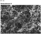
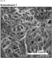
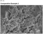
- FIGS. 3a through 3i are SEM images of solid electrolyte films obtained from the examples and comparative examples.
Landscapes
- Chemical & Material Sciences (AREA)
- Physics & Mathematics (AREA)
- General Physics & Mathematics (AREA)
- Immunology (AREA)
- Pathology (AREA)
- General Health & Medical Sciences (AREA)
- Biochemistry (AREA)
- Analytical Chemistry (AREA)
- Life Sciences & Earth Sciences (AREA)
- Health & Medical Sciences (AREA)
- General Chemical & Material Sciences (AREA)
- Electrochemistry (AREA)
- Chemical Kinetics & Catalysis (AREA)
- Manufacturing & Machinery (AREA)
- Engineering & Computer Science (AREA)
- Condensed Matter Physics & Semiconductors (AREA)
- Inorganic Chemistry (AREA)
- Conductive Materials (AREA)
- Secondary Cells (AREA)
- Sampling And Sample Adjustment (AREA)
Abstract
Description
- This application claims the benefit of priority to
Korean Patent Application No. 10-2023-0024417, filed February 23, 2023 - The present disclosure relates to a method for analyzing the structure of a solid electrolyte film.
- Various batteries are being researched to overcome the limitations of current lithium secondary batteries in terms of capacity, safety, power output, enlargement, and miniaturization.
- For example, metal-air batteries with significantly higher theoretical capacity compared to lithium secondary batteries; all-solid-state batteries, which do not have the risk of explosion in terms of safety; supercapacitors in terms of power output; NaS batteries or redox flow batteries (RFBs) in terms of large size, and thin film batteries in terms of miniaturization are being continuously researched in academia and industry.
- A solid-state battery refers to a battery in which part or all of the liquid electrolyte used in a conventional lithium secondary battery is replaced with a solid one, and safety can be greatly improved by not using flammable solvents in the battery, so that ignition or explosion due to decomposition reactions of the conventional electrolyte does not occur at all. In addition, since Li metal or Li alloy can be used as negative electrode material, it has the advantage of dramatically improving the energy density per mass and volume of the battery.
- In particular, among the solid electrolytes in solid-state batteries, mineral-based solid electrolytes can be categorized into sulfide-based and oxide-based solid electrolytes. Currently, the most technologically advanced solid electrolyte is the sulfide-based solid electrolyte, and the ionic conductivity of the solid electrolyte has been developed to the point where materials with ionic conductivity close to that of organic electrolytes are developed.
- In recent years, research has been conducted on techniques to analyze the internal structure of solid electrolytes in order to improve the ionic conductivity of solid electrolytes. However, conventional solid electrolytes have low content of the binder, making it difficult to analyze their structures. Even if the structures of solid electrolyte is to be analyzed, the cross-section observed through Scanning Electron Microscope (SEM) images is two-dimensional (2D), which makes it difficult to analyze the three-dimensional structures.
- Methods for analyzing sulfide-based solid electrolytes using computational modeling have been developed (see Patent Document 1). However, computational simulation indirectly generates the three-dimensional structure of the sulfide-based solid electrolyte based on the conduction properties of lithium ions, so that only the structure of the sulfide-based solid electrolyte is predicted, and the accuracy of the structure analysis of the binder or pores inside the solid electrolyte film is somewhat reduced.
- The present inventors have completed the present disclosure after researching a method for efficiently removing only the solid electrolyte within the solid electrolyte film structure to accurately analyze the solid electrolyte film structure comprising a frame comprising a binder while keeping the solid electrolyte film structure intact.
- (Patent Document 1)
Korean Publication Patent No. 2019-0123002 - The present disclosure seeks to provide a solid electrolyte film structure analysis method for a solid electrolyte film in which only the solid electrolyte in the solid electrolyte film structure can be efficiently removed, leaving the structure of the film intact, to analyze the structure of the solid electrolyte film, more specifically, the structure of the binder.
- According to a first aspect of the present disclosure, the present disclosure provides a method for analyzing a solid electrolyte film structure, comprising the step of: dissolving a solid electrolyte film comprising a solid electrolyte and a binder in a polar solvent.
- In an embodiment of the present disclosure, the polar solvent comprises at least one selected from a group consisting of water and alcohol.
- In an embodiment of the present disclosure, the alcohol is an alcohol with a carbon number of 4 or less.
- In an embodiment of the present disclosure, the solid electrolyte may comprise at least one selected from a group consisting of a sulfide-based solid electrolyte, a halide-based solid electrolyte and an oxide-based solid electrolyte.
- In an embodiment of the present disclosure, the binder comprises a fibrous binder or a particulate binder.
- In an embodiment of the present disclosure, the binder comprises at least one selected from a group consisting of: polytetrafluoroethylene (PTFE), ethylene-vinyl acetate (EVA), styrene-ethylene-butylene-styrene (SEBS), styrene butadiene rubber (SBR), nitrile butadiene rubber (NBR) and hydrogenated nitrile butadiene rubber (HNBR).
- In an embodiment of the present disclosure, the polar solvent in the dissolution step is supplied to achieve a concentration of the solid electrolyte to 10 weight % or less.
- In an embodiment of the present disclosure, the dissolution step is performed for a period of 5 minutes to 1 hour.
- A method for analyzing the structure of a solid electrolyte film according to an embodiment of the present disclosure, by dissolving the solid electrolyte in a solid electrolyte film comprising a solid electrolyte and a binder using a polar solvent that selectively dissolves only the solid electrolyte, effectively removing the solid electrolyte from the solid electrolyte film while leaving the structure of the solid electrolyte film intact by the residual binder.
- As the solid electrolyte is removed from within the solid electrolyte film, the internal structure, such as the connectivity of the binders that comprise the solid electrolyte film, can be readily seen.
-
-
FIG. 1 is a schematic diagram illustrating an analysis process of a solid electrolyte film structure, according to an embodiment. -
FIG. 2 is a photograph illustrating the analysis process of a solid electrolyte film structure, according to an embodiment. -
FIGS. 3a through 3i are scanning electron microscope (SEM) images of a solid electrolyte film obtained in embodiments and comparative examples. - All of the embodiments provided by the present disclosure can be achieved by the following description. It should be understood that the following description describes a preferred embodiment of the present disclosure and is not necessarily limited to the present disclosure.
- For any property described in this specification, if the measurement conditions and methods are not specifically stated, the property shall be measured in accordance with the measurement conditions and methods commonly used by one of ordinary skill in the art.
- As used in this specification, the term "structural analysis of a solid electrolyte film" may refer to analyzing the structure of the binder, i.e., the frame formed by the binder after removal of the solid electrolyte from a solid electrolyte film comprising the solid electrolyte and the binder. The solid electrolyte film may be fabricated by a wet process or a dry process. The wet process uses a solvent, so there may be some residual solvent in the solid electrolyte film, but the residual amount is negligible, and the dry process does not use a solvent, so the solid electrolyte film consists only of the solid electrolyte and the binder, so removing the solid electrolyte from the solid electrolyte film may mean analyzing the structure of the binder.
-
FIG. 1 is a schematic diagram illustrating a method for analyzing a solid electrolyte film structure, according to an embodiment. - Referring to
FIG. 1 , the present disclosure relates to a method for analyzing a solid electrolyte film structure, which may include the step of dissolving a solid electrolyte film comprising a solid electrolyte and a binder by immersing the solid electrolyte film in a polar solvent. After dissolving the solid electrolyte, a framework comprising the binder can be obtained, which can be used to analyze the solid electrolyte film structure. InFIG. 1 , a sulfide-based solid electrolyte film including a sulfide-based solid electrolyte and a fibrous binder is shown as an example, but the present disclosure is not limited thereto. - The method for analyzing a solid electrolyte film structure according to an embodiment of the present disclosure includes a dissolution step of dissolving a solid electrolyte in a solid electrolyte film comprising the solid electrolyte and a binder with a polar solvent. The dissolving step allows for the removal of large chunks of the solid electrolyte that have penetrated into the solid electrolyte film structure. The polar solvent selectively dissolves only the solid electrolyte, but not the binder. According to an embodiment of the present disclosure, the polar solvent may comprise at least one selected from a group consisting of water and alcohol. According to an embodiment of the present disclosure, the alcohol is an alcohol with a carbon number of 4 or less. If the carbon number is too high, the polarity may decrease, reducing its effectiveness as a solvent. Considering the functionality as a solvent and processability of alcohols, ethanol can be desirably utilized.
- According to an embodiment of the present disclosure, in the dissolution step, the polar solvent is supplied such that the concentration of the solid electrolyte is 10 weight % or less, 5 weight % or less, 3 weight % or less, or 1 weight % or less. If the concentration of the solid electrolyte in the polar solvent becomes too high, the solubility of the polar solvent may be reduced and the solid electrolyte may not be effectively removed or additional removal processes may be required. Due to the high content of the solid electrolyte in the solid electrolyte film, the removal process can easily be performed in a single step.
- In the above process, the dissolution time may be from 5 minutes to 1 hour. If it is less than 5 minutes, the solid electrolyte may remain in the solid electrolyte film, and if it is greater than 1 hour, the process may be less efficient. Specifically, the dissolution time may be 5 minutes or more, 8 minutes or more, or 10 minutes or more, and may be 1 hour or less, 50 minutes or less, or 40 minutes or less. A single dissolution step may be sufficient.
- The solid electrolyte may be any solid electrolyte commonly used in the technical field that is soluble in the solvent according to an embodiment of the present disclosure. According to an embodiment of the present disclosure, the solid electrolyte comprises an inorganic solid electrolyte, wherein the inorganic solid electrolyte is a sulfide-based solid electrolyte, a halide-based solid electrolyte, an oxide-based solid electrolyte, or a combination thereof.
- The sulfide-based solid electrolyte includes sulfur atoms among the electrolyte components, but is not limited to any particular component, and may include one or more of crystalline solid electrolytes, amorphous solid electrolytes (glassy solid electrolytes), and glass-ceramic solid electrolytes.
- The sulfide-based solid electrolyte may be one represented by
Formula 1 below:
<Formula 1> La1Mb1Pc1Sd1Ae1
- In
Formula 1 above, L is an element selected from Li, Na and K; M is an element selected from B, Zn, Sn, Si, Cu, Ga, Sb, Al and Ge; A represents I, Br, Cl, or F; and a1-e1 represent the composition ratio of each element, and a1: b1:c1:d1:e1 is 1~12:0~1:1:2-12:0-5. - For example, the sulfide-based solid electrolyte may be LPS-type sulfide containing sulfur and phosphorus, LPSCI-type sulfide, Li4-xGe1-xPxS4(x is from 0.1 to 2, specifically, x is 3/4, 2/3), Li10±1MP2X12(M=Ge, Si, Sn, Al, X=S, Se), Li3.833Sn0.833As0.166S4, Li4SnS4, Li3.25Ge0.25P0.75S4, Li2S-P2S5, B2S3-Li2S, xLi2S-(100-x)P2S5 (x is from 70 to 80), Li2S-LiI-P2S5, Li2S-LiI-Li2O-P2S5, Li2S-LiBr-P2S5, Li2S-LiCl-P2S5, Li2S-Li2O-P2S5, Li2S-Li3PO4-P2S5, Li2S-P2S5-P2O5, Li2S-P2S5-SiS2, Li2S-P2S5-SnS, Li2S-P2S5-Al2S3, Li2S-GeS2, Li2S-GeS2-ZnS, Li2S-SiS2-Li3N, Li2S-SiS2-LiI, or Li2S-B2S3-LiI, although not limited thereto. For example, the above LPSCI-type sulfide may be Li6PS5Cl.
- The halide-based solid electrolyte may be one represented by
Formula 2 below:
<Formula 2> Li6-3aMaBrbClc
- In
Formula 2 above, M is a metal other than Li, a is 0<a<2, b is 0≤b≤6, c is 0≤c≤6, and b+c=6. - For example, the halide-based solid electrolyte may include, but is not necessarily limited to, at least one of Li3YCl6 and Li3YBr6.
- The oxide-based solid electrolyte may be that represented by the following Formula 3:
[Formula 3] Li1+x+yAlxTi2-xSiyP3-yO12
- (In
Formula 3 above, x is 0≤ x ≤2 and y is 0≤ y ≤3.) - For example, the above oxide-based solid electrolyte can be suitably selected from LLT-based with a perovskite structure such as Li3xLa2/3-xTiO3, LISICON such as Li14Zn(GeO4)4, LATP-based such as Li1.3Al0.3Ti1.7(PO4)3, LAGP-based such as (Li1+xGe2-xAlx(PO4)3), phosphate-based such as LiPON, and the like for use, but is not necessarily limited thereto.
- The method for analyzing the solid electrolyte film structure according to an embodiment of the present disclosure can be applied to any solid electrolyte film, provided that the solid electrolyte can be dissolved in a solvent. However, in the wet solid electrolyte film fabrication method in which the solid electrolyte is dissolved in a non-polar solvent with a conductive material and a binder and applied to form a solid electrolyte film structure, the solid electrolyte acts as a support within the solid electrolyte film. Thus, applying the corresponding solid electrolyte film structure analysis method to the solid electrolyte film structure may cause collapse due to dissolution of the solid electrolyte. Therefore, the analysis method for the solid electrolyte film structure can be applied effectively to the solid electrolyte film structure that is fabricated in a dry state by introducing a solid electrolyte into the binder, and the solid electrolyte film structure is sufficiently supported solely by the binder.
- Further, the binder may be a fibrous binder or a particulate binder. The fibrous binder may be in the form of a solid electrolyte incorporated into a solid electrolyte fabricated by physically mixing the binder with the solid electrolyte during a dry process. During the dry process, the binder may be fibrillized by physically mixing to become a fibrous binder.
- The binders may include one or more selected from a group consisting of polytetrafluoroethylene (PTFE), ethylene-vinyl acetate (EVA), styrene-ethylene-butylene-styrene (SEBS), styrene butadiene rubber (SBR), nitrile butadiene rubber (NBR), and hydrogenated nitrile butadiene rubber (HNBR).
- Hereinafter, preferred examples are presented to facilitate the understanding of the present disclosure, but the following examples are provided to facilitate the understanding of the present disclosure, and the present disclosure is not limited to the examples.
[Table 1] Solid electrolyte Binders Weight Ratio (solid electrolyte: binder) Solvent Concentr ation (weight %) Time (min) Example 1 Li6PS5Cl SEBS 97:3 Water 1 10 Example 2 Li6PS5Cl SEBS 97:3 Ethanol 1 10 Example 3 Li6PS5Cl SEBS 97:3 Water 3 20 Example 4 Li6PS5Cl SEBS 97:3 Water 1 30 Example 5 Li6PS5Cl SEBS 98:2 Water 1 10 Example 6 Li6PS5Cl EVA 97:3 Water 1 10 Example 7 Li6PS5Cl PTFE 99.5:0.5 Water 1 10 Example 8 Li6PS5Cl SEBS 97:3 Water 3 1 Comparative Example 1 Li6PS5Cl SEBS 97:3 - - - Comparative Example 2 Li6PS5Cl PTFE 99.5:0.5 - - - - Styrene-ethylene-butylene-styrene (SEBS) particles (Sigma Aldrich, 200557), which is a binder, were dissolved in xylene solvent at 2 weight %, and Li6PS5Cl powder, which is a sulfide-based solid electrolyte, was further mixed to fabricate a uniform slurry. The slurry was then coated on a PET release film, dried, and calendared five times with a roll press to produce a solid electrolyte film with a thickness of about 50 µm. The content of the binder in the fabricated solid electrolyte film was 3 weight %.
- The solid electrolyte film was fixed, and the solid electrolyte in the solid electrolyte film was dissolved for 10 minutes after immersion in a water solvent such that the concentration of the solid electrolyte was 1 weight %. The water solvent was removed from the solid electrolyte film and dried, and the structure of the solid electrolyte film obtained was analyzed (
FIG. 2 ). - The same method was used as in Example 1, except that ethanol solvent was used instead of water solvent.
- The same method was used as in Example 1, except that the water solvent was immersed so that the concentration of the solid electrolyte was 3 weight %, and the dissolution time was 20 minutes.
- The same method was used as in Example 1, except that the dissolution time was 30 minutes.
- The same method was used as in Example 1, except for the content of the binder being 2 weight % in the solid electrolyte film.
- The same method was used as in Example 1, except for using EVA (ethylene-vinyl acetate, Sigma Aldrich, 340502) particles instead of SEBS particles as the binder.
- A mixture obtained by mixing PTFE (polytetrafluoroethylene) particles (Chemours) as a binder with Li6PS5Cl powder, a sulfide-based solid electrolyte, was calendared five times using a roll press to fabricate a solid electrolyte film with a thickness of 300 µm. The content of the binder in the fabricated solid electrolyte film was set to 0.5 weight %.
- The same method was used as in Example 3, except for conducting a solvent treatment for 1 minute on the manufactured solid electrolyte film.
- The solid electrolyte film fabricated in Example 1 was prepared without solvent treatment.
- The solid electrolyte film fabricated in Example 7 was prepared without solvent treatment.
- The structure of the solid electrolyte films obtained from the examples and comparative examples were analyzed using SEM (Thermo Scientific, FEI Apreo SEM).
-
FIGS. 3a through 3i are SEM images of solid electrolyte films obtained from the examples and comparative examples. - Referring to
FIGS. 3a through 3i , it can be seen that in the solid electrolyte film of the examples, only the binder frame was clearly visible after the solid electrolyte was removed. In particular, it can be seen that regardless of the structure of the binder and the fabrication method for the solid electrolyte film, the solid electrolyte contained in the solid electrolyte film was removed using water or ethanol. However, in Example 8, where the dissolution time was relatively short, it can be seen that some solid electrolyte remain. - On the other hand, it can be seen that for the solid electrolyte film of the comparative examples, the solid electrolyte dissolution step is not performed, making it difficult to identify the binder structure.
- Simple modifications or changes of the present disclosure are all within the scope of the present disclosure, and the specific protection scope of the present disclosure will be clarified by the appended claims.
Claims (8)
- A method for analyzing a solid electrolyte film structure, comprising the step of:
dissolving a solid electrolyte film comprising a solid electrolyte and a binder in a polar solvent. - The method for analyzing a solid electrolyte film structure according to claim 1, wherein the polar solvent comprises at least one selected from a group consisting of water and alcohol.
- The method for analyzing a solid electrolyte film structure according to claim 2, wherein the alcohol is an alcohol with a carbon number of 4 or less.
- The method for analyzing a solid electrolyte film structure according to claim 1, wherein the solid electrolyte comprises at least one selected from a group consisting of a sulfide-based solid electrolyte, a halide-based solid electrolyte and an oxide-based solid electrolyte.
- The method for analyzing a solid electrolyte film structure according to claim 1, wherein the binder comprises a fibrous binder or a particulate binder.
- The method for analyzing a solid electrolyte film structure according to claim 1, wherein the binder comprises at least one selected from a group consisting of:
polytetrafluoroethylene (PTFE), ethylene-vinyl acetate (EVA), styrene-ethylene-butylene-styrene (SEBS), styrene butadiene rubber (SBR), nitrile butadiene rubber (NBR) and hydrogenated nitrile butadiene rubber (HNBR). - The method for analyzing a solid electrolyte film structure according to claim 1, wherein the polar solvent in the dissolution step is supplied to achieve a concentration of the solid electrolyte to 10 weight % or less.
- The method for analyzing a solid electrolyte film structure according to claim 1, wherein the dissolution step is performed for a period of 5 minutes to 1 hour.
Applications Claiming Priority (2)
| Application Number | Priority Date | Filing Date | Title |
|---|---|---|---|
| KR1020230024417A KR20240131101A (en) | 2023-02-23 | 2023-02-23 | Solid electrolyte membrane structure analysis method |
| PCT/KR2024/002367 WO2024177421A1 (en) | 2023-02-23 | 2024-02-23 | Method for analyzing structure of solid-state electrolyte film |
Publications (2)
| Publication Number | Publication Date |
|---|---|
| EP4474799A1 true EP4474799A1 (en) | 2024-12-11 |
| EP4474799A4 EP4474799A4 (en) | 2025-07-09 |
Family
ID=92461435
Family Applications (1)
| Application Number | Title | Priority Date | Filing Date |
|---|---|---|---|
| EP24760610.6A Pending EP4474799A4 (en) | 2023-02-23 | 2024-02-23 | Method for analyzing the structure of a solid-state electrolyte film |
Country Status (6)
| Country | Link |
|---|---|
| US (1) | US20240288390A1 (en) |
| EP (1) | EP4474799A4 (en) |
| JP (1) | JP7813014B2 (en) |
| KR (1) | KR20240131101A (en) |
| CN (1) | CN118843790A (en) |
| WO (1) | WO2024177421A1 (en) |
Family Cites Families (14)
| Publication number | Priority date | Publication date | Assignee | Title |
|---|---|---|---|---|
| JP2010123508A (en) * | 2008-11-21 | 2010-06-03 | Toyota Motor Corp | Manufacturing method of electrolyte membrane for fuel cell and electrolyte membrane for fuel cell |
| JP4728385B2 (en) | 2008-12-10 | 2011-07-20 | ナミックス株式会社 | Lithium ion secondary battery and manufacturing method thereof |
| KR101724817B1 (en) * | 2015-01-08 | 2017-04-07 | 현대자동차주식회사 | Process for producting solid electrolyte membrane |
| KR20180021797A (en) | 2015-06-24 | 2018-03-05 | 콴텀스케이프 코포레이션 | Composite electrolyte |
| JP6679736B2 (en) | 2016-09-12 | 2020-04-15 | 出光興産株式会社 | Sulfide solid electrolyte |
| JP7188204B2 (en) * | 2018-03-30 | 2022-12-13 | 東レ株式会社 | Composite electrolyte membrane and membrane electrode assembly using the same, polymer electrolyte fuel cell |
| JP7388192B2 (en) * | 2018-03-30 | 2023-11-29 | 東レ株式会社 | electrolyte membrane |
| KR102070600B1 (en) | 2018-04-23 | 2020-01-29 | 한국과학기술연구원 | An analysis method of sulfide-based solid electrolyte using computer simulation technique and an analysis program of sulfide-based solid electrolyte using computer simulation technique |
| KR102611144B1 (en) * | 2018-07-09 | 2023-12-07 | 주식회사 엘지에너지솔루션 | Qualitative and quantitative analysis method of solid electolyte interphase film of a secondary battery |
| KR102184881B1 (en) * | 2018-11-28 | 2020-12-01 | 서울대학교산학협력단 | Electrode binder for solid electrolyte-based all solid-state lithium secondary battery, cathode in all solid-state lithium secondary battery comprising the same, and solid electrolyte-based all solid-state lithium secondary battery comprising the same |
| WO2020185664A1 (en) | 2019-03-08 | 2020-09-17 | The Penn State Research Foundation | Polymer-inorganic solid-electrolyte interphase for stable metal batteries under lean electrolyte conditions |
| CN113544886B (en) * | 2019-03-08 | 2025-04-15 | 旭化成株式会社 | Electrolyte membrane for redox flow battery, redox flow battery and method for producing electrolyte membrane |
| JP7445505B2 (en) * | 2019-06-11 | 2024-03-07 | 日本特殊陶業株式会社 | Lithium ion conductor, power storage device, and method for manufacturing lithium ion conductor |
| US20230347353A1 (en) | 2020-06-22 | 2023-11-02 | Combinati Incorporated | Systems and methods for analyzing a biological sample |
-
2023
- 2023-02-23 KR KR1020230024417A patent/KR20240131101A/en active Pending
-
2024
- 2024-02-22 US US18/584,514 patent/US20240288390A1/en active Pending
- 2024-02-23 CN CN202480001811.5A patent/CN118843790A/en active Pending
- 2024-02-23 JP JP2024556763A patent/JP7813014B2/en active Active
- 2024-02-23 WO PCT/KR2024/002367 patent/WO2024177421A1/en not_active Ceased
- 2024-02-23 EP EP24760610.6A patent/EP4474799A4/en active Pending
Also Published As
| Publication number | Publication date |
|---|---|
| CN118843790A (en) | 2024-10-25 |
| US20240288390A1 (en) | 2024-08-29 |
| JP2025512280A (en) | 2025-04-17 |
| KR20240131101A (en) | 2024-08-30 |
| JP7813014B2 (en) | 2026-02-12 |
| EP4474799A4 (en) | 2025-07-09 |
| WO2024177421A1 (en) | 2024-08-29 |
Similar Documents
| Publication | Publication Date | Title |
|---|---|---|
| DE112019002427B4 (en) | Rechargeable lithium-ion battery with an anode structure containing a porous zone | |
| CN110277586B (en) | Lithium ion solid electrolyte and preparation method thereof | |
| CN109980211B (en) | Cathode material for sodium ion battery, preparation method and application thereof | |
| DE60123522T2 (en) | Negative electrode for lithium secondary battery | |
| DE102015222553B4 (en) | Cathode for solid-state lithium battery and accumulator using same | |
| CN108511791B (en) | A kind of quasi-solid electrolyte film and its preparation method and application | |
| CN106887639B (en) | A kind of open-frame fluorine-based solid electrolyte material and preparation method thereof | |
| DE112014000685T5 (en) | Electrode materials with a synthetic solid electrolyte interface | |
| EP2769427B1 (en) | Active material for batteries | |
| DE102021101871A1 (en) | LITHIUM PHOSPHATE COATING FOR LITHIUM LANTHANE ZIRCONIUM OXIDE SOLID ELECTROLYTE POWDER | |
| DE102019111405A1 (en) | SULPHIDE AND OXYSULPHIDE GLASS AND CERAMIC SOLID BODY ELECTROLYTE FOR ELECTROCHEMICAL CELLS | |
| Chen et al. | Silver-modified hollow ZnSnO3 boxes as high capacity anode materials for Li-ion batteries | |
| CN105633338A (en) | Preparation method of composite metal anode for secondary battery and product thereof | |
| DE102022107900A1 (en) | COMPOSITE INTERLAYER FOR SOLID STATE BATTERIES BASED ON LITHIUM METAL AND PROCESS FOR THEIR MANUFACTURE | |
| CN117476879A (en) | Preparation method and application of metal lithium foil with lithium metal modification layer | |
| CN115020919A (en) | Coating slurry, diaphragm, preparation method of diaphragm and battery | |
| DE212025000035U1 (en) | Battery cells, battery devices and electrical devices | |
| CN117996163A (en) | High-compactness sulfide electrolyte membrane, preparation method thereof and all-solid-state lithium battery | |
| EP3311440A1 (en) | Sodium-sulfur battery, method for operating same, and use of phosphorus polysulfide as electrolyte additive in sodium-sulfur batteries | |
| CN116417665A (en) | Non-aqueous electrolyte and lithium-ion battery | |
| Zhou et al. | Electrochemo-Mechanics insights of Sn foil anode in Sodium-Ion batteries | |
| DE212025000026U1 (en) | Battery cells, battery devices and electrical equipment | |
| CN104591112A (en) | Manganese-cesium-lithium phosphate as well as preparation method and application thereof | |
| JP7813014B2 (en) | Structural analysis method for solid electrolyte membranes | |
| CN119029306A (en) | Non-aqueous electrolyte and sodium ion battery |
Legal Events
| Date | Code | Title | Description |
|---|---|---|---|
| STAA | Information on the status of an ep patent application or granted ep patent |
Free format text: STATUS: THE INTERNATIONAL PUBLICATION HAS BEEN MADE |
|
| PUAI | Public reference made under article 153(3) epc to a published international application that has entered the european phase |
Free format text: ORIGINAL CODE: 0009012 |
|
| STAA | Information on the status of an ep patent application or granted ep patent |
Free format text: STATUS: REQUEST FOR EXAMINATION WAS MADE |
|
| 17P | Request for examination filed |
Effective date: 20240902 |
|
| AK | Designated contracting states |
Kind code of ref document: A1 Designated state(s): AL AT BE BG CH CY CZ DE DK EE ES FI FR GB GR HR HU IE IS IT LI LT LU LV MC ME MK MT NL NO PL PT RO RS SE SI SK SM TR |
|
| REG | Reference to a national code |
Ref country code: DE Ref legal event code: R079 Free format text: PREVIOUS MAIN CLASS: G01N0023220200 Ipc: G01N0001280000 |
|
| A4 | Supplementary search report drawn up and despatched |
Effective date: 20250610 |
|
| RIC1 | Information provided on ipc code assigned before grant |
Ipc: H01M 8/00 20160101ALI20250603BHEP Ipc: H01M 10/48 20060101ALI20250603BHEP Ipc: H01M 10/0569 20100101ALI20250603BHEP Ipc: H01M 10/0562 20100101ALI20250603BHEP Ipc: G01N 1/28 20060101AFI20250603BHEP |
|
| STAA | Information on the status of an ep patent application or granted ep patent |
Free format text: STATUS: EXAMINATION IS IN PROGRESS |
|
| 17Q | First examination report despatched |
Effective date: 20250902 |
|
| GRAP | Despatch of communication of intention to grant a patent |
Free format text: ORIGINAL CODE: EPIDOSNIGR1 |
|
| STAA | Information on the status of an ep patent application or granted ep patent |
Free format text: STATUS: GRANT OF PATENT IS INTENDED |
|
| DAV | Request for validation of the european patent (deleted) | ||
| DAX | Request for extension of the european patent (deleted) | ||
| INTG | Intention to grant announced |
Effective date: 20260206 |