EP4474773A1 - Azimuth calculation device and azimuth calculation method - Google Patents
Azimuth calculation device and azimuth calculation method Download PDFInfo
- Publication number
- EP4474773A1 EP4474773A1 EP24178986.6A EP24178986A EP4474773A1 EP 4474773 A1 EP4474773 A1 EP 4474773A1 EP 24178986 A EP24178986 A EP 24178986A EP 4474773 A1 EP4474773 A1 EP 4474773A1
- Authority
- EP
- European Patent Office
- Prior art keywords
- azimuth
- angular velocity
- temperature characteristic
- temperature
- azimuth calculation
- Prior art date
- Legal status (The legal status is an assumption and is not a legal conclusion. Google has not performed a legal analysis and makes no representation as to the accuracy of the status listed.)
- Granted
Links
Images



Classifications
-
- G—PHYSICS
- G01—MEASURING; TESTING
- G01C—MEASURING DISTANCES, LEVELS OR BEARINGS; SURVEYING; NAVIGATION; GYROSCOPIC INSTRUMENTS; PHOTOGRAMMETRY OR VIDEOGRAMMETRY
- G01C25/00—Manufacturing, calibrating, cleaning, or repairing instruments or devices referred to in the other groups of this subclass
- G01C25/005—Manufacturing, calibrating, cleaning, or repairing instruments or devices referred to in the other groups of this subclass initial alignment, calibration or starting-up of inertial devices
-
- G—PHYSICS
- G01—MEASURING; TESTING
- G01S—RADIO DIRECTION-FINDING; RADIO NAVIGATION; DETERMINING DISTANCE OR VELOCITY BY USE OF RADIO WAVES; LOCATING OR PRESENCE-DETECTING BY USE OF THE REFLECTION OR RERADIATION OF RADIO WAVES; ANALOGOUS ARRANGEMENTS USING OTHER WAVES
- G01S19/00—Satellite radio beacon positioning systems; Determining position, velocity or attitude using signals transmitted by such systems
- G01S19/38—Determining a navigation solution using signals transmitted by a satellite radio beacon positioning system
- G01S19/39—Determining a navigation solution using signals transmitted by a satellite radio beacon positioning system the satellite radio beacon positioning system transmitting time-stamped messages, e.g. GPS [Global Positioning System], GLONASS [Global Orbiting Navigation Satellite System] or GALILEO
- G01S19/42—Determining position
- G01S19/48—Determining position by combining or switching between position solutions derived from the satellite radio beacon positioning system and position solutions derived from a further system
- G01S19/49—Determining position by combining or switching between position solutions derived from the satellite radio beacon positioning system and position solutions derived from a further system whereby the further system is an inertial position system, e.g. loosely-coupled
-
- G—PHYSICS
- G01—MEASURING; TESTING
- G01C—MEASURING DISTANCES, LEVELS OR BEARINGS; SURVEYING; NAVIGATION; GYROSCOPIC INSTRUMENTS; PHOTOGRAMMETRY OR VIDEOGRAMMETRY
- G01C1/00—Measuring angles
-
- G—PHYSICS
- G01—MEASURING; TESTING
- G01C—MEASURING DISTANCES, LEVELS OR BEARINGS; SURVEYING; NAVIGATION; GYROSCOPIC INSTRUMENTS; PHOTOGRAMMETRY OR VIDEOGRAMMETRY
- G01C21/00—Navigation; Navigational instruments not provided for in groups G01C1/00 - G01C19/00
- G01C21/005—Navigation; Navigational instruments not provided for in groups G01C1/00 - G01C19/00 with correlation of navigation data from several sources, e.g. map or contour matching
-
- G—PHYSICS
- G01—MEASURING; TESTING
- G01C—MEASURING DISTANCES, LEVELS OR BEARINGS; SURVEYING; NAVIGATION; GYROSCOPIC INSTRUMENTS; PHOTOGRAMMETRY OR VIDEOGRAMMETRY
- G01C21/00—Navigation; Navigational instruments not provided for in groups G01C1/00 - G01C19/00
- G01C21/10—Navigation; Navigational instruments not provided for in groups G01C1/00 - G01C19/00 by using measurements of speed or acceleration
- G01C21/12—Navigation; Navigational instruments not provided for in groups G01C1/00 - G01C19/00 by using measurements of speed or acceleration executed aboard the object being navigated; Dead reckoning
- G01C21/16—Navigation; Navigational instruments not provided for in groups G01C1/00 - G01C19/00 by using measurements of speed or acceleration executed aboard the object being navigated; Dead reckoning by integrating acceleration or speed, i.e. inertial navigation
- G01C21/165—Navigation; Navigational instruments not provided for in groups G01C1/00 - G01C19/00 by using measurements of speed or acceleration executed aboard the object being navigated; Dead reckoning by integrating acceleration or speed, i.e. inertial navigation combined with non-inertial navigation instruments
-
- G—PHYSICS
- G01—MEASURING; TESTING
- G01S—RADIO DIRECTION-FINDING; RADIO NAVIGATION; DETERMINING DISTANCE OR VELOCITY BY USE OF RADIO WAVES; LOCATING OR PRESENCE-DETECTING BY USE OF THE REFLECTION OR RERADIATION OF RADIO WAVES; ANALOGOUS ARRANGEMENTS USING OTHER WAVES
- G01S19/00—Satellite radio beacon positioning systems; Determining position, velocity or attitude using signals transmitted by such systems
- G01S19/38—Determining a navigation solution using signals transmitted by a satellite radio beacon positioning system
- G01S19/39—Determining a navigation solution using signals transmitted by a satellite radio beacon positioning system the satellite radio beacon positioning system transmitting time-stamped messages, e.g. GPS [Global Positioning System], GLONASS [Global Orbiting Navigation Satellite System] or GALILEO
- G01S19/42—Determining position
- G01S19/45—Determining position by combining measurements of signals from the satellite radio beacon positioning system with a supplementary measurement
Definitions
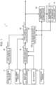
- FIG. 1 is a diagram illustrating a configuration example of an azimuth calculation device according to a first embodiment.
- an azimuth calculation device 1 according to the first embodiment includes a first azimuth calculation unit 20, a second azimuth calculation unit 30, a third azimuth calculation unit 40, an angular velocity bias prediction unit 50, a temperature characteristic estimation unit 60, and a storage unit 70.
- the azimuth calculation device 1 may include a satellite signal receiver 11, a wheel speed sensor 12, an angular velocity sensor 13, a 6DoF sensor 14, and a temperature sensor 15. Dof is an abbreviation for degrees of freedom.
- the azimuth calculation device 1 may have a configuration in which some of the components in FIG. 1 are omitted or changed or other components are added.
- the 6DoF sensor 14 detects angular velocities around three axes perpendicular to each other and accelerations in the directions of the three axes, and outputs three-axis angular velocity signals and three-axis accelerations signals.
- the 6DoF sensor 14 has three detection axes perpendicular to each other, and is mounted on the moving body such that the three detection axes extend along the X-axis, the Y-axis, and the Z-axis, respectively.
- the 6DoF sensor 14 detects an angular velocity around the X-axis, an angular velocity around the Y-axis, and an angular velocity around the Z-axis and outputs three-axis angular velocity signals, and detects an acceleration in the X-axis direction, an acceleration in the Y-axis direction, and an acceleration in the Z-axis direction and outputs three-axis acceleration signals.
- the 6DoF sensor 14 may be a capacitive sensor obtained by processing a silicon substrate using a MEMS technique.
- the angular velocity sensor 13 and the 6DoF sensor 14 may be housed in one housing so that the detection axis of the angular velocity sensor 13 and any one of the three detection axes of the 6DoF sensor 14 are in the same direction, thereby forming a sensor module 10 that detects angular velocities around the three axes and accelerations in the directions of the three axes.
- the sensor module 10 is mounted on a vehicle 5, which is a moving body, such that the three axes extend along the X-axis, the Y-axis, and the Z-axis.
- the sensor module 10 may output data including the angular velocity around the Z-axis detected by the angular velocity sensor 13 and the angular velocity around the X-axis, the angular velocity around the Y-axis, and the accelerations in the directions of the three axes detected by the 6DoF sensor 14.
- the angular velocity sensor 13 and the 6DoF sensor 14 may be separate bodies.
- the temperature sensor 15 detects a temperature and outputs a temperature signal.
- the temperature sensor 15 is disposed in the vicinity of the angular velocity sensor 13 and detects the temperature of the angular velocity sensor 13.
- the angular velocity sensor 13 and the temperature sensor 15 may be housed in one housing.
- the first azimuth calculation unit 20 calculates, based on the satellite signal received by the satellite signal receiver 11, a first azimuth ⁇ gnss,k , which is the azimuth of the moving body in the global coordinate system at time k.
- the first azimuth calculation unit 20 calculates the first azimuth ⁇ gnss,k at a predetermined period, for example, every one second.
- the first azimuth calculation unit 20 may calculate the velocity vector of the moving body by using a phenomenon in which the frequency of the satellite signal shifts according to the relationship between the position of the satellite and the velocity of the moving body due to the Doppler effect, and may calculate the first azimuth ⁇ gnss,k from the direction of the velocity vector.
- the first azimuth calculation unit 20 may calculate based on the satellite signal, the position of the moving body in the global coordinate system, calculate a velocity vector by differentiating the position, and calculate the first azimuth ⁇ gnss,k from the direction of the velocity vector.
- antennas for receiving satellite signals may be provided at two different positions of the moving body, the satellite signal receiver 11 may calculate the positions of the two antennas based on the satellite signals received by the two antennas, and the first azimuth ⁇ gnss,k may be calculated from the two calculated positions.
- two satellite signal receivers 11 may be mounted on the moving body, two positions may be calculated based on the respective satellite signals received by the two satellite signal receivers 11, and the first azimuth ⁇ gnss,k may be calculated from the two calculated positions.
- the first azimuth calculation unit 20 may further calculate the position or the speed of the moving body in the global coordinate system by using known satellite navigation.
- the second azimuth calculation unit 30 calculates, based on the angular velocity signal output from the angular velocity sensor 13, a second azimuth ⁇ ins,k , which is the azimuth of the moving body in the global coordinate system at time k.
- the second azimuth calculation unit 30 calculates the second azimuth ⁇ ins,k at time k with the angular velocity bias corrected, based on the angular velocity bias ⁇ k-1 at the last time k-1 predicted by the angular velocity bias prediction unit 50.
- the second azimuth calculation unit 30 calculates the second azimuth ⁇ ins,k at a predetermined period, for example, every 0.01 seconds.
- the pitch angle ⁇ is a rotation angle with the Y-axis in the right direction perpendicular to the traveling direction of the vehicle 5 as a rotation axis.
- the yaw angle ⁇ is a rotation angle with the Z-axis in the downward direction perpendicular to the plane on which the vehicle 5 travels as a rotation axis.
- the yaw angle ⁇ indicates the relative azimuth of the moving body, and the roll angle ⁇ and the pitch angle ⁇ indicate the posture of the moving body.
- the third azimuth calculation unit 40 calculates the third azimuth ⁇ est,k , which is the azimuth of the moving body in the global coordinate system at time k, based on the first azimuth ⁇ gnss,k at time k calculated by the first azimuth calculation unit 20 and the second azimuth ⁇ ins,k at time k calculated by the second azimuth calculation unit 30.
- the third azimuth calculation unit 40 calculates the third azimuth ⁇ est,k at a predetermined period, for example, every one second by using known composite navigation in which the satellite navigation and the inertial navigation are combined.
- the third azimuth calculation unit 40 may set the first azimuth ⁇ gnss,k as the third azimuth ⁇ est,k at the timing when the first azimuth ⁇ gnss,k is calculated, and may set the second azimuth ⁇ ins,k as the third azimuth ⁇ est,k at the timing when the first azimuth ⁇ gnss,k is not calculated.
- the third azimuth calculation unit 40 may calculate the third azimuth ⁇ est,k by using a Kalman filter.
- the third azimuth calculation unit 40 may further calculate the position of the moving body based on the speed, the posture, and the azimuth of the moving body.
- the speed of the moving body may be a speed calculated by the first azimuth calculation unit 20, or may be a speed calculated based on the wheel speed signal output from the wheel speed sensor 12.
- the posture of the moving body may be expressed by the roll angle ⁇ est,k and the pitch angle ⁇ est,k , and the roll angle ⁇ and the pitch angle ⁇ may be calculated by the second azimuth calculation unit 30.
- the storage unit 70 stores temperature characteristic information 71 of an angular velocity bias ⁇ k .
- the angular velocity bias ⁇ k is the bias of the angular velocity of the second azimuth ⁇ ins,k calculated by the second azimuth calculation unit 30, and is expressed by Equation (2).
- ⁇ ins,k in Equation (2) is an error of the second azimuth ⁇ ins,k , and is a difference between the second azimuth ⁇ ins,k and the third azimuth ⁇ est,k at time k calculated by the third azimuth calculation unit 40 as shown in Equation (3).
- ⁇ t in Equation (2) is a period at which the third azimuth calculation unit 40 calculates the third azimuth ⁇ est,k .
- ⁇ t is 1 second.
- the angular velocity bias ⁇ k is approximated by an n-th degree polynomial having a temperature change ⁇ T k at time k as a variable as in Equation (4).
- the temperature change ⁇ T k is a difference between the temperature T k at time k and the temperature T k at time k-1 detected by the temperature sensor 15.
- the temperature characteristic information 71 includes values of coefficients c 0,k to c n,k of the polynomial (4) for each of a plurality of temperatures.
- FIG. 3 is a diagram illustrating an example of the temperature characteristic information 71.
- the temperature characteristic information 71 includes values of coefficients c 0,k to c n,k for each temperature in units of 1°C of -40°C to +85°C.
- the temperature characteristic information 71 does not necessarily include at least one of the values of the coefficients c 0,k to c n,k for at least one temperature.
- the temperature characteristic estimation unit 60 estimates the temperature characteristic of the angular velocity bias ⁇ k for the temperature T k detected by the temperature sensor 15, based on the second azimuth ⁇ ins,k calculated by the second azimuth calculation unit 30 and the third azimuth ⁇ est,k calculated by the third azimuth calculation unit 40, and updates the temperature characteristic information 71 stored in the storage unit 70 based on the estimated temperature characteristic.
- the temperature characteristic estimation unit 60 may estimate the values of the coefficients c 0,k to c n,k of the polynomial (4) as the temperature characteristic of the angular velocity bias ⁇ k for the temperature T k and calculate the variances of the estimated coefficients c 0,k to c n,k .
- the temperature characteristic estimation unit 60 may update the value of the coefficient c i,k included in the temperature characteristic information 71 to the estimated value of the coefficient c i,k when the variance of the coefficient c i,k is equal to or less than a predetermined threshold value, and may not update the value of the coefficient c i,k included in the temperature characteristic information 71 when the variance of the coefficient c i,k is larger than the predetermined threshold value.
- the temperature characteristic estimation unit 60 may update the value of the coefficient c i,k for the temperature T k , which is included in the temperature characteristic information 71, only when the estimation accuracy of the value of the coefficient c i,k for the temperature T k is equal to or greater than a predetermined value.
- the temperature characteristic estimation unit 60 updates the values c 0(+25°C) to c n(+25°C) of the coefficients c 0,k to c n,k for 25°C included in the temperature characteristic information 71 to the estimated values of the coefficients c 0,k to c n,k .
- the temperature characteristic estimation unit 60 may update the values of the coefficients c 0,k to c n,k included in the temperature characteristic information 71 to the estimated values of the coefficients c 0,k to c n,k regardless of the values of the variances.
- the temperature characteristic estimation unit 60 estimates the temperature characteristic of the angular velocity bias ⁇ k at a predetermined period at which the third azimuth ⁇ est,k is updated, for example, at a short period such as one second. Therefore, in each period in which the temperature characteristic estimation unit 60 estimates the temperature characteristic, the temperature change ⁇ T k is small. As illustrated in FIG. 4 , when the temperature change ⁇ T k is small, the angular velocity bias ⁇ k can be regarded as changing linearly for the temperature change ⁇ T k . That is, the angular velocity bias ⁇ k is approximated by a linear polynomial of the temperature change ⁇ T k as shown in Equation (5).
- the temperature characteristic estimation unit 60 may estimate the first-order coefficient c 1,k and the zero-order coefficient c 0,k of the polynomial in Equation (5) for the temperature T k according to the temperature signal output from the temperature sensor 15.
- the temperature characteristic estimation unit 60 estimates the first-order coefficient c 1,k and the zero-order coefficient c 0,k for the temperature T k by using an extended Kalman filter.
- Equation (6) a state variable x k having the first-order coefficient c 1,k , the zero-order coefficient c 0,k , and the temperature T k as its elements is defined.
- x k c 1 , k c 0 , k T k
- Equation (7) F k is a state transition matrix, and is assumed to be 3 ⁇ 3 unit matrix as shown in Equation (8).
- v k is drive noise, and has, as its elements, ⁇ v1 , ⁇ v2 , and ⁇ v3 that are set to appropriate values in advance as shown in Equation (9).
- x k F k x k ⁇ 1 + v k
- Equation (10) an observation variable y k having the angular velocity bias ⁇ k , an angular velocity bias change ⁇ k - ⁇ k-1 , and the temperature T k as its elements is defined.
- y k ⁇ k ⁇ k ⁇ ⁇ k ⁇ 1 T k
- Equation (11) H k is the observation Jacobian, and is expressed by Equation (12).
- Equation (12) w k is observation noise, and has, as its elements, ⁇ w1 , ⁇ w2 , and ⁇ w3 that are set to appropriate values in advance as shown in Equation (13).
- the temperature characteristic estimation unit 60 executes a prediction step, an observation step, and an update step of the extended Kalman filter, and estimates the temperature characteristic of the angular velocity bias ⁇ k .
- the temperature characteristic estimation unit 60 predicts a state variable x ⁇ k
- k ⁇ 1 F k x ⁇ k ⁇ 1
- k ⁇ 1 x ⁇ k ⁇ 1
- the temperature characteristic estimation unit 60 predicts, by using Equation (15), the covariance matrix P k
- V k is a covariance matrix of the drive noise v k , and is calculated by Equation (16).
- the temperature characteristic estimation unit 60 calculates a value to be observed from the state variables x ⁇ k
- the temperature change ⁇ T k is, as in Equation (18), a difference between the temperature T k
- the temperature change ⁇ T k-1 is, as in Equation (19), a difference between the temperature T k-1
- the temperature characteristic estimation unit 60 calculates, by using Equation (20), an observation residual e k , which is a difference between the value of the observation variable y k at time k of actual observation and the value calculated by Equation (17).
- e k y k ⁇ h x ⁇ k
- the temperature characteristic estimation unit 60 calculates, by using Equation (21), the covariance matrix S k of the observation residual e k from the covariance matrix P k
- W k is a covariance matrix of the observation noise w k , and is calculated by Equation (22).
- H k is an observation Jacobian matrix, and is calculated by Equation (23).
- the temperature characteristic estimation unit 60 calculates, by using Equation (24), a Kalman gain K k from the covariance matrix P k
- K k P k
- the temperature characteristic estimation unit 60 updates, by using Equation (25), the state variable x ⁇ k
- k-1 is a priori estimation value at time k.
- k is a posteriori estimation value at time k.
- the temperature characteristic estimation unit 60 estimates, by using the extended Kalman filter, the first-order coefficient c 1,k and the zero-order coefficient c 0,k included in the state variables x k .
- the temperature characteristic estimation unit 60 updates, by using Equation (26), the covariance matrix P k
- the temperature characteristic estimation unit 60 updates the value of the first-order coefficient c 1,k included in the temperature characteristic information 71 to the estimated value of the first-order coefficient c 1,k when the variance p 11 is equal to or less than a predetermined threshold value and does not update the value of the first-order coefficient c 1,k included in the temperature characteristic information 71 when the variance p 11 is larger than the predetermined threshold value.
- the first azimuth calculation unit 20 of the azimuth calculation device 1 calculates the first azimuth ⁇ gnss,k based on the satellite signal received by the satellite signal receiver 11.
- the second azimuth calculation unit 30 of the azimuth calculation device 1 calculates the second azimuth ⁇ ins,k based on the angular velocity signal output from the angular velocity sensor 13 detecting the angular velocity.
- the second azimuth calculation unit 30 calculates the second azimuth ⁇ ins,k with the angular velocity bias corrected, based on the angular velocity bias ⁇ k-1 last time predicted in the angular velocity bias prediction step S50 to be described later.
- the temperature characteristic estimation unit 60 of the azimuth calculation device 1 estimates, based on the second azimuth ⁇ ins,k calculated in the second azimuth calculation step S20 and the third azimuth ⁇ est,k calculated in the third azimuth calculation step S30, the temperature characteristic of the angular velocity biases ⁇ k for the temperature T k detected by the temperature sensors 15, and updates, based on the estimated temperature characteristic, the temperature characteristic information 71 of the angular velocity bias ⁇ k stored in the storage unit 70.
- the angular velocity bias prediction unit 50 of the azimuth calculation device 1 predicts the angular velocity bias ⁇ k based on the temperature T k detected by the temperature sensor 15 and the temperature characteristic information 71 stored in the storage unit 70.
- the azimuth calculation device 1 repeatedly performs steps S10 to S50 until the azimuth calculation process ends in step S60.
- step S1 the azimuth calculation device 1 initializes time k to 0.
- Step S11 corresponds to the first azimuth calculation step S10 in FIG. 5 .
- step S21 the second azimuth calculation unit 30 of the azimuth calculation device 1 sets the initial value of the second azimuth ⁇ ins,k .
- the third azimuth ⁇ est,k-1 last time calculated in step S31 described later is set as the initial value of the second azimuth ⁇ ins,k .
- the second azimuth calculation unit 30 sets the second azimuth ⁇ ins,k-1 last time calculated in step S23, which will be described later, as the initial value of the second azimuth ⁇ ins,k .
- time k is 0, the second azimuth calculation unit 30 sets the second azimuth ⁇ ins,k to an appropriate initial value.
- the second azimuth calculation unit 30 calculates, by using Equation (1) above, the angular velocity of the yaw angle ⁇ based on the angular velocity ⁇ z,k around the Z-axis detected by the angular velocity sensor 13, and corrects the bias of the angular velocity of the yaw angle ⁇ by subtracting the angular velocity bias ⁇ k-1 last time predicted in step S51, which will be described later, from the angular velocity of the yaw angle ⁇ .
- step S23 a value obtained by integrating the angular velocity of the yaw angle ⁇ whose bias has been corrected in step S21 is added to the initial value of the second azimuth ⁇ ins,k set in step S22 to calculate the second azimuth ⁇ ins,k with the angular velocity bias corrected.
- Steps S21, S22, and S23 correspond to the second azimuth calculation step S20 in FIG. 5 .
- step S31 the third azimuth calculation unit 40 of the azimuth calculation device 1 calculates the third azimuth ⁇ est,k based on the first azimuth ⁇ gnss,k calculated in step S11 and the second azimuth ⁇ ins,k calculated in step S23.
- step S30 when the first azimuth ⁇ gnss,k is not calculated in step S11, the third azimuth calculation unit 40 does not perform the processing of step S31.
- Step S31 corresponds to the third azimuth calculation step S30 in FIG. 5 .
- step S41 the temperature characteristic estimation unit 60 of the azimuth calculation device 1 calculates, by using Equation (3) above, an error ⁇ ins,k of the second azimuth ⁇ ins,k .
- step S42 the temperature characteristic estimation unit 60 calculates, by using Equation (2) above, the angular velocity bias ⁇ k , which is the bias of the angular velocity of the second azimuth ⁇ ins,k .
- the temperature characteristic estimation unit 60 calculates the temperature characteristic of the angular velocity bias ⁇ k . Specifically, the temperature characteristic estimation unit 60 calculates the observation variable y k shown in Equation (10) above based on the angular velocity bias ⁇ k calculated in step S42 and the temperature T k detected by the temperature sensor 15, and calculates, by using the extended Kalman filter described above, the state variable x k having, as its elements, the first-order coefficient c 1,k , the zero-order coefficient c 0,k , and the temperature T k of the above polynomial (5) shown in Equation (6) above.
- step S44 the temperature characteristic estimation unit 60 updates the temperature characteristic information 71 stored in the storage unit 70. Specifically, the temperature characteristic estimation unit 60 calculates the covariance matrix P k
- the temperature characteristic estimation unit 60 updates the value of the coefficient c 1,k included in the temperature characteristic information 71 to the estimated value of the coefficient c 1,k when the variance p 11 is equal to or less than a predetermined threshold value and does not update the value of the coefficient c 1,k included in the temperature characteristic information 71 when the variance p 11 is larger than the predetermined threshold value.
- the temperature characteristic estimation unit 60 updates the value of the first-order coefficient c 1,k included in the temperature characteristic information 71 to the estimated value of the first-order coefficient c 1,k regardless of the value of the variance p 11 .
- the temperature characteristic estimation unit 60 updates the value of the zero-order coefficient c 0,k included in the temperature characteristic information 71 to the estimated value of the zero-order coefficient c 0,k when the variance p 22 is equal to or less than a predetermined threshold value and does not update the value of the zero-order coefficient c 0,k included in the temperature characteristic information 71 when the variance p 22 is larger than the predetermined threshold value.
- the temperature characteristic estimation unit 60 updates the value of the zero-order coefficient c 0,k included in the temperature characteristic information 71 to the estimated value of the zero-order coefficient c 0,k regardless of the value of the variance p 22 .
- Steps S41, S42, S43, and S44 correspond to the temperature characteristic estimation step S40 in FIG. 5 .
- step S51 the angular velocity bias prediction unit 50 of the azimuth calculation device 1 predicts the angular velocity bias ⁇ k of the second azimuth ⁇ ins,k based on the temperature characteristic information 71 stored in the storage unit 70.
- the angular velocity bias prediction unit 50 may predict the angular velocity bias ⁇ k by substituting the temperature T k-1 , the temperature T k , and the first-order coefficient c 1,k and the zero-order coefficient c 0,k for the temperature T k included in the temperature characteristic information 71 into the linear polynomial (5).
- Step S51 corresponds to the angular velocity bias prediction step S50 in FIG. 5 .
- the azimuth calculation device 1 increases time k by 1 in step S58, and repeatedly performs steps S2 to S58 until the azimuth calculation process ends in step S60.
- the azimuth calculation device 1 can estimate the angular velocity bias ⁇ k at a predetermined period, for example, every one second, regardless of whether the vehicle 5 as a moving body is stopped or traveling, and calculate the highly accurate third azimuth ⁇ est,k with the angular velocity bias corrected.
- the first azimuth calculation unit 20 can calculate the first azimuth ⁇ gnss,k based on the satellite signal regardless of whether the moving body on which the azimuth calculation device 1 is mounted is stopped or traveling, and the second azimuth calculation unit 30 can calculate the second azimuth ⁇ ins,k based on the angular velocity signal output from the angular velocity sensor 13 even when a satellite signal cannot be received. Therefore, the third azimuth calculation unit 40 can seamlessly and periodically calculate the third azimuth ⁇ est,k based on the first azimuth ⁇ gnss,k and the second azimuth ⁇ ins,k .
- the temperature characteristic estimation unit 60 can periodically estimate the temperature characteristic of the angular velocity bias ⁇ k of the second azimuth ⁇ ins,k based on the second azimuth ⁇ ins,k and the third azimuth ⁇ est,k and can update the temperature characteristic information 71 stored in the storage unit 70. Therefore, the second azimuth calculation unit 30 can calculate the second azimuth ⁇ ins,k with the angular velocity bias corrected, based on the angular velocity bias ⁇ k-1 last time predicted by the angular velocity bias prediction unit 50 based on the temperature characteristic information 71.
- the azimuth calculation device 1 can calculate the azimuth with the angular velocity bias corrected with high accuracy regardless of whether the moving body is stopped or traveling.
- the angular velocity bias ⁇ k is not approximated by a polynomial having the temperature T k as a variable, but is approximated by the polynomial (4) having the temperature change ⁇ T k as a variable. Therefore, the temperature characteristic estimation unit 60 can accurately estimate the temperature characteristic of the angular velocity bias ⁇ k for each narrow temperature range. In a narrow temperature range, the angular velocity bias ⁇ k is accurately approximated by the linear polynomial (5) having the temperature change ⁇ T k as a variable. Therefore, it is possible to reduce the calculation load for estimation while maintaining the estimation accuracy of the temperature characteristic of the angular velocity bias ⁇ k by the temperature characteristic estimation unit 60.
- the angular velocity bias prediction unit 50 can accurately predict the angular velocity bias ⁇ k based on the temperature characteristic information 71. Therefore, according to the first embodiment, the azimuth calculation device 1 can calculate the azimuth with the angular velocity bias corrected with high accuracy.
- the second azimuth calculation unit 30 calculates a second azimuth ⁇ ins,k , which is the azimuth of the moving body in the global coordinate system at time k, based on the angular velocity signal output from the angular velocity sensor 13.
- the second azimuth calculation unit 30 calculates the second azimuth ⁇ ins,k at time k with the angular velocity bias corrected, based on the angular velocity bias ⁇ k-1 at the last time k-1 predicted by the angular velocity bias prediction unit 50.
- the second azimuth calculation unit 30 calculates the second azimuth ⁇ ins,k at time k by adding, to the third azimuth ⁇ est,k-1 , a value, which is obtained by integrating the angular velocity of the yaw angle ⁇ obtained by substituting the angular velocity around the Z-axis into Equation (1).
- the temperature characteristic estimation unit 60 estimates the first-order coefficient c 1,k and the zero-order coefficient c 0,k of the linear polynomial (5) for the temperature T k by using the extended Kalman filter similar to that in the first embodiment.
- the angular velocity bias prediction unit 50 predicts the angular velocity bias ⁇ k based on the temperature T k detected by the temperature sensor 15 and the temperature characteristic information 71 stored in the storage unit 70. For example, the angular velocity bias prediction unit 50 may predict the angular velocity bias ⁇ k by substituting the temperature T k-1 , the temperature T k , and the coefficient c 0,k to c n,k for the temperature T k included in the temperature characteristic information 71 into the above polynomial (4).
- the other configurations and functions of the azimuth calculation device 1 according to the second embodiment are the same as those in the first embodiment, and accordingly, description thereof will be omitted.
- FIG. 7 is a flowchart illustrating an example of the specific procedure of an azimuth calculation method according to a second embodiment.
- the same steps as those in FIG. 6 are denoted by the same reference numerals.
- step S1 the azimuth calculation device 1 initializes time k to 0.
- Step S11 corresponds to the first azimuth calculation step S10 in FIG. 5 .
- step S21 the second azimuth calculation unit 30 of the azimuth calculation device 1 sets the initial value of the second azimuth ⁇ ins,k .
- the third azimuth ⁇ est,k-1 last time calculated in step S31 described later is set as the initial value of the second azimuth ⁇ ins,k .
- the second azimuth calculation unit 30 sets the second azimuth ⁇ ins,k-1 last time calculated in step S23a, which will be described later, as the initial value of the second azimuth ⁇ ins,k .
- time k is 0, the second azimuth calculation unit 30 sets the second azimuth ⁇ ins,k to an appropriate initial value.
- step S22a the second azimuth calculation unit 30 corrects the angular velocity bias around the yaw axis by subtracting the angular velocity bias ⁇ k-1 last time predicted in step S51a, which will be described later, from the angular velocity ⁇ z,k around the Z-axis detected by the angular velocity sensor 13.
- step S23a the second azimuth calculation unit 30 adds, to the initial value of the second azimuth ⁇ ins,k set in step S21, a value obtained by integrating the angular velocity of the yaw angle ⁇ obtained by substituting the angular velocity around the yaw axis whose bias has been corrected in step S22a into Equation (1) above to calculate the second azimuth ⁇ ins,k .
- Steps S21, S22a, and S23a correspond to the second azimuth calculation step S20 in FIG. 5 .
- step S31 the third azimuth calculation unit 40 of the azimuth calculation device 1 calculates, in step S31, the third azimuth ⁇ est,k based on the first azimuth ⁇ gnss,k calculated in step S11 and the second azimuth ⁇ ins,k calculated in step S23a.
- step S30 when the first azimuth ⁇ gnss,k is not calculated in step S11, the third azimuth calculation unit 40 does not perform the processing of step S31.
- step S31 the third azimuth calculation unit 40 also calculates the roll angle ⁇ est,k and the pitch angle ⁇ est,k .
- Step S31 corresponds to the third azimuth calculation step S30 in FIG. 5 .
- step S41 the temperature characteristic estimation unit 60 of the azimuth calculation device 1 calculates an error ⁇ ins,k of the second azimuth ⁇ ins,k by using Equation (3) above.
- step S42a the temperature characteristic estimation unit 60 calculates the angular velocity bias ⁇ k , which is the bias of the angular velocity ⁇ z,k around the yaw axis, by using Equation (27) above.
- the temperature characteristic estimation unit 60 calculates the temperature characteristic of the angular velocity bias ⁇ k . Specifically, the temperature characteristic estimation unit 60 calculates the observation variable y k shown in Equation (10) above based on the angular velocity bias ⁇ k calculated in step S42a and the temperature T k detected by the temperature sensor 15, and calculates the state variable x k having, as its elements, the first-order coefficient c 1,k , the zero-order coefficient c 0,k , and the temperature T k of the above polynomial (5) shown in Equation (6) above by using the extended Kalman filter described above.
- step S44a the temperature characteristic estimation unit 60 updates the temperature characteristic information 71 stored in the storage unit 70. Specifically, the temperature characteristic estimation unit 60 calculates the covariance matrix P k
- the temperature characteristic estimation unit 60 updates the value of the first-order coefficient c 1,k included in the temperature characteristic information 71 to the estimated value of the first-order coefficient c 1,k regardless of the value of the variance p 11 .
- the temperature characteristic estimation unit 60 updates the value of the zero-order coefficient c 0,k included in the temperature characteristic information 71 to the estimated value of the zero-order coefficient c 0,k when the variance p 22 is equal to or less than a predetermined threshold value and does not update the value of the zero-order coefficient c 0,k included in the temperature characteristic information 71 when the variance p 22 is larger than the predetermined threshold value.
- the temperature characteristic estimation unit 60 updates the value of the zero-order coefficient c 0,k included in the temperature characteristic information 71 to the estimated value of the zero-order coefficient c 0,k regardless of the value of the variance p 22 .
- Steps S41, S42a, S43a, and S44a correspond to the temperature characteristic estimation step S40 in FIG. 5 .
- step S51a the angular velocity bias prediction unit 50 of the azimuth calculation device 1 predicts the angular velocity bias ⁇ k around the yaw axis based on the temperature characteristic information 71 stored in the storage unit 70.
- the angular velocity bias prediction unit 50 may predict the angular velocity bias ⁇ k by substituting the temperature T k-1 , the temperature T k , and the first-order coefficient c 1,k and the zero-order coefficient c 0,k for the temperature T k included in the temperature characteristic information 71 into the linear polynomial (5).
- Step S51a corresponds to the angular velocity bias prediction step S50 in FIG. 5 .
- the azimuth calculation device 1 increases time k by 1 in step S58, and repeatedly performs steps S2 to S58 until the azimuth calculation process ends in step S60.
- the temperature characteristic estimation unit 60 can periodically estimate, based on the second azimuth ⁇ ins,k and the third azimuth ⁇ est,k , the temperature characteristic of the angular velocity bias ⁇ k of the angular velocity ⁇ z,k around the yaw axis detected by the angular velocity sensor 13 and can update the temperature characteristic information 71 stored in the storage unit 70. Therefore, the second azimuth calculation unit 30 can calculate the second azimuth ⁇ ins,k with the angular velocity bias corrected, based on the angular velocity bias ⁇ k-1 last time predicted by the angular velocity bias prediction unit 50 based on the temperature characteristic information 71.
- the azimuth calculation device 1 can calculate the azimuth with the angular velocity bias corrected with high accuracy regardless of whether the moving body is stopped or traveling.
- the same effects as those in the first embodiment can be obtained.
- FIG. 8 is a diagram illustrating a configuration example of an azimuth calculation device 1 according to the third embodiment.
- the azimuth calculation device 1 according to the third embodiment includes, similarly to the first embodiment, a first azimuth calculation unit 20, a second azimuth calculation unit 30, a third azimuth calculation unit 40, an angular velocity bias prediction unit 50, a temperature characteristic estimation unit 60, and a storage unit 70.
- the azimuth calculation device 1 may include a wheel speed sensor 12, an angular velocity sensor 13, a 6DoF sensor 14, a temperature sensor 15, and an external sensor 16.
- the azimuth calculation device 1 may have a configuration in which some of the components in FIG. 8 are omitted or changed or other components are added.
- the third embodiment is different from the first and second embodiments in that the first azimuth calculation unit 20 performs processing using the external sensor 16 instead of the satellite signal receiver 11.
- the external sensor 16 is a sensor that detects information around the moving body, and may be, for example, a LiDAR, a camera, and a millimeter wave radar that are used for AD, ADAS, and the like.
- AD is an abbreviation for autonomous driving
- ADAS is an abbreviation for advanced driver assistance system.
- LiDAR is an abbreviation for light detection and ranging or laser imaging detection and ranging.
- the first azimuth calculation unit 20 calculates a first azimuth ⁇ EXT,k , which is the azimuth of the moving body in the global coordinate system at time k, based on the detection result of the external sensor 16.
- the first azimuth calculation unit 20 calculates the first azimuth ⁇ EXT,k at a predetermined period, for example, every one second.
- the first azimuth calculation unit 20 calculates the first azimuth ⁇ EXT,k , which is the azimuth of the moving body in the global coordinate system, by comparing the information around the moving body, which is the detection result of the external sensor 16, with map information 72 stored in the storage unit 70.
- the first azimuth calculation unit 20 may further calculate the position or the speed of the moving body in the global coordinate system.
- the second azimuth calculation unit 30 calculates, based on the angular velocity signal output from the angular velocity sensor 13, the second azimuth ⁇ ins,k , which is the azimuth of the moving body in the global coordinate system at time k.
- the second azimuth calculation unit 30 calculates the second azimuth ⁇ ins,k at time k with the angular velocity bias corrected, based on the angular velocity bias ⁇ k-1 at the last time k-1 predicted by the angular velocity bias prediction unit 50.
- the third azimuth calculation unit 40 calculates the third azimuth ⁇ est,k , which is the azimuth of the moving body in the global coordinate system at time k, based on the first azimuth ⁇ EXT,k at time k calculated by the first azimuth calculation unit 20 and the second azimuth ⁇ ins,k at time k calculated by the second azimuth calculation unit 30.
- the third azimuth calculation unit 40 calculates the third azimuth ⁇ est,k at a predetermined period, for example, every one second.
- the third azimuth calculation unit 40 may set the first azimuth ⁇ EXT,k as the third azimuth ⁇ est,k at the timing when the first azimuth ⁇ EXT,k is calculated, and may set the second azimuth ⁇ ins,k as the third azimuth ⁇ est,k at the timing when the first azimuth ⁇ EXT,k is not calculated.
- the third azimuth calculation unit 40 may calculate the third azimuth ⁇ est,k by using a Kalman filter.
- the storage unit 70 stores the temperature characteristic information 71 of the angular velocity bias ⁇ k .
- the angular velocity bias ⁇ k may be a bias of the angular velocity of the second azimuth ⁇ ins,k calculated by the second azimuth calculation unit 30, as illustrated in Equation (2) above.
- the angular velocity bias ⁇ k may be a bias of the angular velocity ⁇ z,k around the yaw axis detected by the angular velocity sensor 13, as illustrated in Equation (27) above.
- the storage unit 70 stores the map information 72 used for calculation of the first azimuth ⁇ EXT,k by the first azimuth calculation unit 20.
- the temperature characteristic estimation unit 60 estimates the temperature characteristic of the angular velocity bias ⁇ k for the temperature T k detected by the temperature sensor 15, based on the second azimuth ⁇ ins,k calculated by the second azimuth calculation unit 30 and the third azimuth ⁇ est,k calculated by the third azimuth calculation unit 40, and updates the temperature characteristic information 71 stored in the storage unit 70, based on the estimated temperature characteristic.
- the temperature characteristic estimation unit 60 may estimate the first-order coefficient c 1,k and the zero-order coefficient c 0,k for the temperature T k by using an extended Kalman filter.
- the angular velocity bias prediction unit 50 predicts the angular velocity bias ⁇ k based on the temperature T k detected by the temperature sensor 15 and the temperature characteristic information 71 stored in the storage unit 70. As described above, the angular velocity bias prediction unit 50 may predict the angular velocity bias ⁇ k by substituting the temperature T k-1 , the temperature T k , and the coefficient c 0,k to c n,k for the temperature T k included in the temperature characteristic information 71 into the above polynomial (4).
- the other configurations and functions of the azimuth calculation device 1 according to the third embodiment are the same as those of the azimuth calculation device 1 according to the first embodiment or the second embodiment, and accordingly, description thereof will be omitted.
- a flowchart illustrating an example of the procedure of an azimuth calculation method according to the third embodiment is the same as FIG. 5 , and accordingly, illustration thereof will be omitted.
- the first azimuth calculation unit 20 of the azimuth calculation device 1 calculates the first azimuth ⁇ EXT,k based on the detection result of the external sensor 16.
- the processing from the second azimuth calculation step S20 in FIG. 5 which is performed by the azimuth calculation device 1, is the same as that in the first embodiment or the second embodiment except that the first azimuth ⁇ EXT,k is used instead of the first azimuth ⁇ gnss,k , and accordingly, description thereof will be omitted.
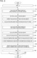
- FIG. 9 is a flowchart illustrating an example of the specific procedure of the azimuth calculation method according to the third embodiment.
- the same steps as those in FIG. 6 are denoted by the same reference numerals.
- the angular velocity bias ⁇ k is the bias of the angular velocity of the second azimuth ⁇ ins,k .
- step S1 the azimuth calculation device 1 initializes time k to 0.
- step S12 the first azimuth calculation unit 20 of the azimuth calculation device 1 calculates the first azimuth ⁇ EXT,k based on the detection result of the external sensor 16.
- Step S12 corresponds to the first azimuth calculation step S10 in FIG. 5 .
- the second azimuth calculation unit 30 of the azimuth calculation device 1 calculates, by performing the same processing as steps S21, S22, and S23 in FIG. 6 , the second azimuth ⁇ ins,k with the angular velocity bias corrected.
- Steps S21, S22, and S23 correspond to the second azimuth calculation step S20 in FIG. 5 .
- step S31 the third azimuth calculation unit 40 of the azimuth calculation device 1 calculates the third azimuth ⁇ est,k based on the first azimuth ⁇ EXT,k calculated in step S12 and the second azimuth ⁇ ins,k calculated in step S23.
- Step S31 corresponds to the third azimuth calculation step S30 in FIG. 5 .
- the temperature characteristic estimation unit 60 of the azimuth calculation device 1 performs processing similar to that in steps S41, S42, S43, and S44 in FIG. 6 and updates the temperature characteristic information 71 stored in the storage unit 70.
- Steps S41, S42, S43, and S44 correspond to the temperature characteristic estimation step S40 in FIG. 5 .
- step S51 the angular velocity bias prediction unit 50 of the azimuth calculation device 1performs processing similar to that in step S51 in FIG. 6 and predicts the angular velocity bias ⁇ k of the second azimuth ⁇ ins,k .
- the azimuth calculation device 1 increases time k by 1 in step S58, and repeatedly performs steps S2 to S58 until the azimuth calculation process ends in step S60.
- FIG. 10 is a flowchart illustrating another example of the specific procedure of the azimuth calculation method according to the third embodiment.
- the same steps as those in FIG. 7 are denoted by the same reference numerals.
- the angular velocity bias ⁇ k may be the bias of the angular velocity ⁇ z,k around the yaw axis detected by the angular velocity sensor 13.
- step S1 the azimuth calculation device 1 initializes time k to 0.
- step S12 the first azimuth calculation unit 20 of the azimuth calculation device 1 calculates the first azimuth ⁇ EXT,k based on the detection result of the external sensor 16.
- Step S12 corresponds to the first azimuth calculation step S10 in FIG. 5 .
- the second azimuth calculation unit 30 of the azimuth calculation device 1 performs processing similar to that in steps S21, S22a, and S23a in FIG. 7 and calculates the second azimuth ⁇ ins,k with the angular velocity bias corrected.
- Steps S21, S22a, and S23a correspond to the second azimuth calculation step S20 in FIG. 5 .
- step S31 the third azimuth calculation unit 40 of the azimuth calculation device 1 calculates the third azimuth ⁇ est,k based on the first azimuth ⁇ EXT,k calculated in step S12 and the second azimuth ⁇ ins,k calculated in step S23a.
- Step S31 corresponds to the third azimuth calculation step S30 in FIG. 5 .
- the temperature characteristic estimation unit 60 of the azimuth calculation device 1 performs processing similar to that in steps S41, S42a, S43a, and S44a in FIG. 7 and updates the temperature characteristic information 71 stored in the storage unit 70.
- Steps S41, S42a, S43a, and S44a correspond to the temperature characteristic estimation step S40 in FIG. 5 .
- step S51a the angular velocity bias prediction unit 50 of the azimuth calculation device 1 performs processing similar to that in step S51a in FIG. 7 and predicts the angular velocity bias ⁇ k around the yaw axis.
- the azimuth calculation device 1 increases time k by 1 in step S58, and repeatedly performs steps S2 to S58 until the azimuth calculation process ends in step S60.
- the first azimuth calculation unit 20 can calculate the first azimuth ⁇ EXT,k based on the detection result of the external sensor 16 regardless of whether the moving body on which the azimuth calculation device 1 is mounted is stopped or traveling, and the second azimuth calculation unit 30 can calculate the second azimuth ⁇ ins,k based on the angular velocity signal output from the angular velocity sensor 13. Therefore, the third azimuth calculation unit 40 can seamlessly and periodically calculate the third azimuth ⁇ est,k based on the first azimuth ⁇ EXT,k and the second azimuth ⁇ ins,k .
- the temperature characteristic estimation unit 60 can periodically estimate the temperature characteristic of the angular velocity bias ⁇ k based on the second azimuth ⁇ ins,k and the third azimuth ⁇ est,k and can update the temperature characteristic information 71 stored in the storage unit 70. Therefore, the second azimuth calculation unit 30 can calculate the second azimuth ⁇ ins,k with the angular velocity bias corrected, based on the angular velocity bias ⁇ k-1 last time predicted by the angular velocity bias prediction unit 50 based on the temperature characteristic information 71.
- the temperature characteristic estimation unit 60 estimates the temperature characteristic of the angular velocity bias ⁇ k for the temperature T k detected by the temperature sensor 15, it is possible to accurately estimate the temperature characteristic of the angular velocity bias ⁇ k for each narrow temperature range. Therefore, according to the third embodiment, the azimuth calculation device 1 can calculate the azimuth with the angular velocity bias corrected with high accuracy regardless of whether the moving body is stopped or traveling. In addition, according to the third embodiment, the same effects as those in the first embodiment or the second embodiment can be obtained.
- the azimuth calculation device 1 may be mounted on a moving body other than the vehicle
- the moving body include not only a vehicle but also an agricultural machine such as a tractor, a construction machine such as an excavator, an unmanned transport vehicle, a robot lawn mower, a robot vacuum cleaner, aircraft such as jet aircraft and helicopter, a ship, a rocket, a satellite, and a railroad vehicle.
- the azimuth calculation device 1 includes the angular velocity sensor 13 and the 6DoF sensor 14 in each of the above embodiments, the azimuth calculation device 1 may include other sensors instead of these.
- the azimuth calculation device 1 may include two 6DoF sensors.
- the present disclosure includes a configuration that is substantially the same as the configuration described in the embodiments, for example, a configuration that has the same function, method, and result, or a configuration that has the same purpose and effect.
- the present disclosure includes a configuration in which non-essential portions of the configuration described in the embodiments are replaced.
- the present disclosure includes a configuration having the same function and effect as the configuration described in the embodiments or a configuration capable of achieving the same object.
- the present disclosure includes a configuration in which a known technique is added to the configuration described in the embodiments.
- An azimuth calculation device includes: a first azimuth calculation unit that calculates a first azimuth based on a satellite signal received by a satellite signal receiver or a detection result of an external sensor; a second azimuth calculation unit that calculates a second azimuth based on an angular velocity signal output from an angular velocity sensor detecting an angular velocity; a third azimuth calculation unit that calculates a third azimuth based on the first azimuth and the second azimuth; a storage unit that stores temperature characteristic information of an angular velocity bias; a temperature characteristic estimation unit that estimates, based on the second azimuth and the third azimuth, a temperature characteristic of the angular velocity bias for a temperature detected by a temperature sensor and updates, based on the estimated temperature characteristic, the temperature characteristic information stored in the storage unit; and an angular velocity bias prediction unit that predicts the angular velocity bias based on the temperature detected by the temperature sensor and the temperature characteristic information stored in the storage unit.
- the second azimuth calculation unit
- the first azimuth calculation unit can calculate the first azimuth based on the satellite signal or the detection result of the external sensor regardless of whether the moving body on which the azimuth calculation device is mounted is stopped or traveling, and the second azimuth calculation unit can calculate the second azimuth based on the angular velocity signal even when a satellite signal cannot be received. Therefore, the third azimuth calculation unit can seamlessly and periodically calculate the third azimuth based on the first azimuth and the second azimuth. As a result, even when the moving body is traveling, the temperature characteristic estimation unit can periodically estimate, based on the second azimuth and the third azimuth, the temperature characteristic of the angular velocity bias and can update the temperature characteristic information.
- the second azimuth calculation unit can calculate the second azimuth with the angular velocity bias corrected, based on the angular velocity bias last time predicted by the angular velocity bias prediction unit based on the temperature characteristic information.
- the temperature characteristic estimation unit estimates the temperature characteristic of the angular velocity bias for the temperature detected by the temperature sensor, it is possible to accurately estimate the temperature characteristic of the angular velocity bias for each narrow temperature range. Therefore, according to this azimuth calculation device, it is possible to calculate the azimuth with the angular velocity bias corrected with high accuracy regardless of whether the moving body is stopped or traveling.
- the angular velocity bias may be approximated by a polynomial having a temperature change as a variable.
- the temperature characteristic estimation unit can accurately estimate the temperature characteristic of the angular velocity bias for each narrow temperature range.
- the temperature characteristic information may include a value of a coefficient of the polynomial for each of a plurality of temperatures.
- the polynomial may be a linear polynomial.
- the angular velocity bias is accurately approximated in a narrow temperature range by the linear polynomial having a temperature change as a variable. Therefore, it is possible to reduce the calculation load for estimation while maintaining the estimation accuracy of the temperature characteristic of the angular velocity bias by the temperature characteristic estimation unit.
- the angular velocity bias may be a bias of an angular velocity of the second azimuth.
- the angular velocity bias may be a bias of an angular velocity around a yaw axis detected by the angular velocity sensor.
- the temperature characteristic estimation unit may estimate the value of the coefficient as the temperature characteristic and calculate a variance of the estimated coefficient, and in a case in which the temperature characteristic information includes the value of the coefficient for the temperature detected by the temperature sensor, the temperature characteristic estimation unit may update the value of the coefficient included in the temperature characteristic information to the estimated value of the coefficient when the variance is equal to or less than a predetermined threshold value and may not update the value of the coefficient included in the temperature characteristic information when the variance is larger than the predetermined threshold value.
- the angular velocity bias prediction unit can accurately predict the angular velocity bias based on the temperature characteristic information. Therefore, according to this azimuth calculation device, it is possible to calculate the azimuth with the angular velocity bias corrected with high accuracy.
- An azimuth calculation method includes: a first azimuth calculation step of calculating a first azimuth based on a satellite signal received by a satellite signal receiver or a detection result of an external sensor; a second azimuth calculation step of calculating a second azimuth based on an angular velocity signal output from an angular velocity sensor detecting an angular velocity; a third azimuth calculation step of calculating a third azimuth based on the first azimuth and the second azimuth; a temperature characteristic estimation step of estimating, based on the second azimuth and the third azimuth, a temperature characteristic of an angular velocity bias for a temperature detected by a temperature sensor and updating, based on the estimated temperature characteristic, temperature characteristic information of the angular velocity bias stored in a storage unit; and an angular velocity bias prediction step of predicting the angular velocity bias based on the temperature detected by the temperature sensor and the temperature characteristic information stored in the storage unit.
- the second azimuth calculation step the second azimuth calculation step of
- the first azimuth can be calculated based on the satellite signal or the detection result of the external sensor in the first azimuth calculation step regardless of whether the moving body is stopped or traveling, and the second azimuth can be calculated based on the angular velocity signal in the second azimuth calculation step even when a satellite signal cannot be received. Therefore, in the third azimuth calculation step, it is possible to seamlessly and periodically calculate the third azimuth based on the first azimuth and the second azimuth. As a result, even when the moving body is traveling, in the temperature characteristic estimation step, it is possible to periodically estimate, based on the second azimuth and the third azimuth, the temperature characteristic of the angular velocity bias and update the temperature characteristic information.
- the second azimuth calculation step it is possible to calculate the second azimuth with the angular velocity bias corrected, based on the angular velocity bias last time predicted based on the temperature characteristic information in the angular velocity bias prediction step.
- the temperature characteristic of the angular velocity bias for the temperature detected by the temperature sensor is estimated in the temperature characteristic estimation step, it is possible to accurately estimate the temperature characteristic of the angular velocity bias for each narrow temperature range. Therefore, according to this azimuth calculation method, it is possible to calculate the azimuth with the angular velocity bias corrected with high accuracy regardless of whether the moving body is stopped or traveling.
Landscapes
- Engineering & Computer Science (AREA)
- Radar, Positioning & Navigation (AREA)
- Remote Sensing (AREA)
- Physics & Mathematics (AREA)
- General Physics & Mathematics (AREA)
- Automation & Control Theory (AREA)
- Computer Networks & Wireless Communication (AREA)
- Manufacturing & Machinery (AREA)
- Gyroscopes (AREA)
- Navigation (AREA)
Abstract
Description
- The present application is based on, and claims priority from
JP Application Serial Number 2023-090752, filed June 1, 2023 - The present disclosure relates to an azimuth calculation device and an azimuth calculation method.
-
JP-A-2009-192495 - However, in the control device described in
JP-A-2009-192495 - An azimuth calculation device according to an aspect of the present disclosure includes: a first azimuth calculation unit that calculates a first azimuth based on a satellite signal received by a satellite signal receiver or a detection result of an external sensor; a second azimuth calculation unit that calculates a second azimuth based on an angular velocity signal output from an angular velocity sensor detecting an angular velocity; a third azimuth calculation unit that calculates a third azimuth based on the first azimuth and the second azimuth; a storage unit that stores temperature characteristic information of an angular velocity bias; a temperature characteristic estimation unit that estimates, based on the second azimuth and the third azimuth, a temperature characteristic of the angular velocity bias for a temperature detected by a temperature sensor and updates, based on the estimated temperature characteristic, the temperature characteristic information stored in the storage unit; and an angular velocity bias prediction unit that predicts the angular velocity bias based on the temperature detected by the temperature sensor and the temperature characteristic information stored in the storage unit. The second azimuth calculation unit calculates, based on the angular velocity bias last time predicted by the angular velocity bias prediction unit, the second azimuth with the angular velocity bias corrected.
- An azimuth calculation method according to another aspect of the present disclosure includes: a first azimuth calculation step of calculating a first azimuth based on a satellite signal received by a satellite signal receiver or a detection result of an external sensor; a second azimuth calculation step of calculating a second azimuth based on an angular velocity signal output from an angular velocity sensor detecting an angular velocity; a third azimuth calculation step of calculating a third azimuth based on the first azimuth and the second azimuth; a temperature characteristic estimation step of estimating, based on the second azimuth and the third azimuth, a temperature characteristic of an angular velocity bias for a temperature detected by a temperature sensor and updating, based on the estimated temperature characteristic, temperature characteristic information of the angular velocity bias stored in a storage unit; and an angular velocity bias prediction step of predicting the angular velocity bias based on the temperature detected by the temperature sensor and the temperature characteristic information stored in the storage unit. In the second azimuth calculation step, the second azimuth with the angular velocity bias corrected is calculated based on the angular velocity bias last time predicted in the angular velocity bias prediction step.
-
-
FIG. 1 is a diagram illustrating a configuration example of an azimuth calculation device according to a first embodiment; -
FIG. 2 is an explanatory diagram of an X-axis, a Y-axis, and a Z-axis; -
FIG. 3 is a diagram illustrating an example of temperature characteristic information; -
FIG. 4 is a graph illustrating an example of a temperature characteristic of angular velocity bias; -
FIG. 5 is a flowchart illustrating an example of a procedure of an azimuth calculation method according to the present embodiment; -
FIG. 6 is a flowchart illustrating an example of the specific procedure of an azimuth calculation method according to a first embodiment; -
FIG. 7 is a flowchart illustrating an example of the specific procedure of an azimuth calculation method according to a second embodiment; -
FIG. 8 is a diagram illustrating a configuration example of an azimuth calculation device according to a third embodiment; -
FIG. 9 is a flowchart illustrating an example of the specific procedure of an azimuth calculation method according to the third embodiment; and -
FIG. 10 is a flowchart illustrating another example of the specific procedure of the azimuth calculation method according to the third embodiment. - Hereinafter, preferred embodiments of the present disclosure will be described in detail with reference to the drawings. It should be noted that the embodiments described below do not unduly limit the contents of the present disclosure described in the appended claims. In addition, all of the configurations described below are not necessarily essential components of the present disclosure.
-
FIG. 1 is a diagram illustrating a configuration example of an azimuth calculation device according to a first embodiment. As illustrated inFIG. 1 , anazimuth calculation device 1 according to the first embodiment includes a firstazimuth calculation unit 20, a secondazimuth calculation unit 30, a thirdazimuth calculation unit 40, an angular velocitybias prediction unit 50, a temperaturecharacteristic estimation unit 60, and astorage unit 70. Theazimuth calculation device 1 may include asatellite signal receiver 11, awheel speed sensor 12, anangular velocity sensor 13, a6DoF sensor 14, and atemperature sensor 15. Dof is an abbreviation for degrees of freedom. Theazimuth calculation device 1 may have a configuration in which some of the components inFIG. 1 are omitted or changed or other components are added. - The
azimuth calculation device 1 is mounted on a moving body. A local coordinate system, which is a three-axis coordinate system including an X-axis, a Y-axis, and a Z-axis, is defined in a moving body on which theazimuth calculation device 1 is mounted. The X-axis is an axis in which the traveling direction of the moving body is positive, the Y-axis is an axis in which a right direction perpendicular to the traveling direction of the moving body is positive, and the Z-axis is an axis in which a downward direction perpendicular to a plane on which the moving body travels is positive. In addition, a global coordinate system is defined in a space in which the moving body moves. The global coordinate system is a coordinate system fixed to the earth. In the following description, it is assumed that theazimuth calculation device 1 is mounted on a vehicle which is a moving body. - The
satellite signal receiver 11 receives, via an antenna (not shown), a satellite signal transmitted from a satellite. The satellite forms a part of a satellite positioning system. The satellite positioning system may be a global navigation satellite system (GNSS). Examples of the GNSS include GPS (Global Positioning System), EGNOS (European Geostationary Navigation Overlay Service), QZSS (Quasi Zenith Satellite System), GLONASS (Global Navigation Satellite System), GALILEO, and BeiDou (BeiDou Navigation Satellite System). - The
wheel speed sensor 12 detects a rotational speed of a wheel of a vehicle, which is a moving body, and outputs a wheel speed signal. - The
angular velocity sensor 13 detects an angular velocity and outputs an angular velocity signal. Specifically, theangular velocity sensor 13 has one detection axis and is mounted on the moving body such that the detection axis extends along the Z-axis. Theangular sensor 13 detects an angular velocity around the Z-axis and outputs a Z-axis angular velocity signal. For example, theangular velocity sensor 13 may be a crystal gyro sensor that has a sensor element (not shown) made of crystal and detects an angular velocity with high accuracy. - The
6DoF sensor 14 detects angular velocities around three axes perpendicular to each other and accelerations in the directions of the three axes, and outputs three-axis angular velocity signals and three-axis accelerations signals. Specifically, the6DoF sensor 14 has three detection axes perpendicular to each other, and is mounted on the moving body such that the three detection axes extend along the X-axis, the Y-axis, and the Z-axis, respectively. The6DoF sensor 14 detects an angular velocity around the X-axis, an angular velocity around the Y-axis, and an angular velocity around the Z-axis and outputs three-axis angular velocity signals, and detects an acceleration in the X-axis direction, an acceleration in the Y-axis direction, and an acceleration in the Z-axis direction and outputs three-axis acceleration signals. For example, the6DoF sensor 14 may be a capacitive sensor obtained by processing a silicon substrate using a MEMS technique. - For example, the
angular velocity sensor 13 and the6DoF sensor 14 may be housed in one housing so that the detection axis of theangular velocity sensor 13 and any one of the three detection axes of the6DoF sensor 14 are in the same direction, thereby forming asensor module 10 that detects angular velocities around the three axes and accelerations in the directions of the three axes. In this case, for example, as illustrated inFIG. 2 , thesensor module 10 is mounted on avehicle 5, which is a moving body, such that the three axes extend along the X-axis, the Y-axis, and the Z-axis. Theangular velocity sensor 13 detects an angular velocity around the Z-axis, and the6DoF sensor 14 detects an angular velocity around the X-axis, an angular velocity around the Y-axis, an angular velocity around the Z-axis, an acceleration in the X-axis direction, an acceleration in the Y-axis direction, and an acceleration in the Z-axis direction. Thesensor module 10 may output data including the angular velocity around the Z-axis detected by theangular velocity sensor 13 and the angular velocities around the three axes and the accelerations in the directions of the three axes detected by the6DoF sensor 14. For example, when the angular velocity around the Z-axis detected by theangular velocity sensor 13 is more accurate than the angular velocity around the Z-axis detected by the6DoF sensor 14, thesensor module 10 may output data including the angular velocity around the Z-axis detected by theangular velocity sensor 13 and the angular velocity around the X-axis, the angular velocity around the Y-axis, and the accelerations in the directions of the three axes detected by the6DoF sensor 14. - Here, the
angular velocity sensor 13 and the6DoF sensor 14 may be separate bodies. - The
temperature sensor 15 detects a temperature and outputs a temperature signal. For example, thetemperature sensor 15 is disposed in the vicinity of theangular velocity sensor 13 and detects the temperature of theangular velocity sensor 13. Alternatively, theangular velocity sensor 13 and thetemperature sensor 15 may be housed in one housing. - The first
azimuth calculation unit 20 calculates, based on the satellite signal received by thesatellite signal receiver 11, a first azimuth Ψgnss,k, which is the azimuth of the moving body in the global coordinate system at time k. The firstazimuth calculation unit 20 calculates the first azimuth Ψgnss,k at a predetermined period, for example, every one second. For example, the firstazimuth calculation unit 20 may calculate the velocity vector of the moving body by using a phenomenon in which the frequency of the satellite signal shifts according to the relationship between the position of the satellite and the velocity of the moving body due to the Doppler effect, and may calculate the first azimuth Ψgnss,k from the direction of the velocity vector. In addition, for example, the firstazimuth calculation unit 20 may calculate based on the satellite signal, the position of the moving body in the global coordinate system, calculate a velocity vector by differentiating the position, and calculate the first azimuth Ψgnss,k from the direction of the velocity vector. For example, antennas for receiving satellite signals may be provided at two different positions of the moving body, thesatellite signal receiver 11 may calculate the positions of the two antennas based on the satellite signals received by the two antennas, and the first azimuth Ψgnss,k may be calculated from the two calculated positions. Alternatively, twosatellite signal receivers 11 may be mounted on the moving body, two positions may be calculated based on the respective satellite signals received by the twosatellite signal receivers 11, and the first azimuth Ψgnss,k may be calculated from the two calculated positions. The firstazimuth calculation unit 20 may further calculate the position or the speed of the moving body in the global coordinate system by using known satellite navigation. - The second
azimuth calculation unit 30 calculates, based on the angular velocity signal output from theangular velocity sensor 13, a second azimuth Ψins,k, which is the azimuth of the moving body in the global coordinate system at time k. The secondazimuth calculation unit 30 calculates the second azimuth Ψins,k at time k with the angular velocity bias corrected, based on the angular velocity bias δΩk-1 at the last time k-1 predicted by the angular velocitybias prediction unit 50. The secondazimuth calculation unit 30 calculates the second azimuth Ψins,k at a predetermined period, for example, every 0.01 seconds. Specifically, the secondazimuth calculation unit 30 calculates the angular velocities of the roll angle φ, the pitch angle θ, and the yaw angle ψ by using Equation (1) based on the angular velocity ωz around the Z-axis at time k detected by theangular velocity sensor 13 and the angular velocity ωx around the X-axis and the angular velocity ωy around the Y-axis at time k detected by the6DoF sensor 14. As illustrated inFIG. 2 , the roll angle φ is a rotation angle with the X-axis in the traveling direction of thevehicle 5 as a rotation axis. In addition, the pitch angle θ is a rotation angle with the Y-axis in the right direction perpendicular to the traveling direction of thevehicle 5 as a rotation axis. In addition, the yaw angle ψ is a rotation angle with the Z-axis in the downward direction perpendicular to the plane on which thevehicle 5 travels as a rotation axis. The yaw angle ψ indicates the relative azimuth of the moving body, and the roll angle φ and the pitch angle θ indicate the posture of the moving body.
- With a third azimuth Ψest,k-1 at the last time k-1 calculated by the third
azimuth calculation unit 40 as the initial azimuth, the secondazimuth calculation unit 30 calculates the second azimuth Ψins,k at time k by adding a value, which is obtained by subtracting the angular velocity bias δΩk-1 from the angular velocity of the yaw angle ψ and integrating the subtraction result, to the third azimuth Ψest,k-1. In the traveling control of thevehicle 5, the yaw angle ψ is most important among the roll angle φ, the pitch angle θ, and the yaw angle ψ. Therefore, in order to calculate the yaw angle ψ with high accuracy, theazimuth calculation device 1 includes, in addition to the6DoF sensor 14, theangular velocity sensor 13 that detects the angular velocity around the Z-axis with high accuracy. - The third
azimuth calculation unit 40 calculates the third azimuth Ψest,k, which is the azimuth of the moving body in the global coordinate system at time k, based on the first azimuth Ψgnss,k at time k calculated by the firstazimuth calculation unit 20 and the second azimuth Ψins,k at time k calculated by the secondazimuth calculation unit 30. The thirdazimuth calculation unit 40 calculates the third azimuth Ψest,k at a predetermined period, for example, every one second by using known composite navigation in which the satellite navigation and the inertial navigation are combined. For example, the thirdazimuth calculation unit 40 may set the first azimuth Ψgnss,k as the third azimuth Ψest,k at the timing when the first azimuth Ψgnss,k is calculated, and may set the second azimuth Ψins,k as the third azimuth Ψest,k at the timing when the first azimuth Ψgnss,k is not calculated. In addition, the thirdazimuth calculation unit 40 may calculate the third azimuth Ψest,k by using a Kalman filter. The thirdazimuth calculation unit 40 may further calculate the position of the moving body based on the speed, the posture, and the azimuth of the moving body. The speed of the moving body may be a speed calculated by the firstazimuth calculation unit 20, or may be a speed calculated based on the wheel speed signal output from thewheel speed sensor 12. In addition, the posture of the moving body may be expressed by the roll angle Φest,k and the pitch angle Θest,k, and the roll angle φ and the pitch angle θ may be calculated by the secondazimuth calculation unit 30. - The
storage unit 70 stores temperaturecharacteristic information 71 of an angular velocity bias δΩk. In the present embodiment, the angular velocity bias δΩk is the bias of the angular velocity of the second azimuth Ψins,k calculated by the secondazimuth calculation unit 30, and is expressed by Equation (2). δΨins,k in Equation (2) is an error of the second azimuth Ψins,k, and is a difference between the second azimuth Ψins,k and the third azimuth Ψest,k at time k calculated by the thirdazimuth calculation unit 40 as shown in Equation (3). Δt in Equation (2) is a period at which the thirdazimuth calculation unit 40 calculates the third azimuth Ψest,k. For example, Δt is 1 second.

- The angular velocity bias δΩk is approximated by an n-th degree polynomial having a temperature change ΔTk at time k as a variable as in Equation (4). The temperature change ΔTk is a difference between the temperature Tk at time k and the temperature Tk at time k-1 detected by the
temperature sensor 15.
- In the present embodiment, the temperature
characteristic information 71 includes values of coefficients c0,k to cn,k of the polynomial (4) for each of a plurality of temperatures.FIG. 3 is a diagram illustrating an example of the temperaturecharacteristic information 71. In the example ofFIG. 3 , the temperaturecharacteristic information 71 includes values of coefficients c0,k to cn,k for each temperature in units of 1°C of -40°C to +85°C. The temperaturecharacteristic information 71 does not necessarily include at least one of the values of the coefficients c0,k to cn,k for at least one temperature. - The temperature
characteristic estimation unit 60 estimates the temperature characteristic of the angular velocity bias δΩk for the temperature Tk detected by thetemperature sensor 15, based on the second azimuth Ψins,k calculated by the secondazimuth calculation unit 30 and the third azimuth Ψest,k calculated by the thirdazimuth calculation unit 40, and updates the temperaturecharacteristic information 71 stored in thestorage unit 70 based on the estimated temperature characteristic. The temperaturecharacteristic estimation unit 60 may estimate the values of the coefficients c0,k to cn,k of the polynomial (4) as the temperature characteristic of the angular velocity bias δΩk for the temperature Tk and calculate the variances of the estimated coefficients c0,k to cn,k. In a case in which the temperaturecharacteristic information 71 includes the value of the coefficient ci,k of the polynomial (4) for the temperature Tk, the temperaturecharacteristic estimation unit 60 may update the value of the coefficient ci,k included in the temperaturecharacteristic information 71 to the estimated value of the coefficient ci,k when the variance of the coefficient ci,k is equal to or less than a predetermined threshold value, and may not update the value of the coefficient ci,k included in the temperaturecharacteristic information 71 when the variance of the coefficient ci,k is larger than the predetermined threshold value. That is, the temperaturecharacteristic estimation unit 60 may update the value of the coefficient ci,k for the temperature Tk, which is included in the temperaturecharacteristic information 71, only when the estimation accuracy of the value of the coefficient ci,k for the temperature Tk is equal to or greater than a predetermined value. In a case in which the temperaturecharacteristic information 71 illustrated inFIG. 3 is stored in thestorage unit 70, for example, when the temperature Tk is 25°C and the variances of the coefficients c0,k to cn,k are all equal to or less than a predetermined threshold value, the temperaturecharacteristic estimation unit 60 updates the values c0(+25°C) to cn(+25°C) of the coefficients c0,k to cn,k for 25°C included in the temperaturecharacteristic information 71 to the estimated values of the coefficients c0,k to cn,k. - When the temperature
characteristic information 71 does not include the values of the coefficients c0,k to cn,k of the polynomial (4) for the temperature Tk, the temperaturecharacteristic estimation unit 60 may update the values of the coefficients c0,k to cn,k included in the temperaturecharacteristic information 71 to the estimated values of the coefficients c0,k to cn,k regardless of the values of the variances. - The temperature
characteristic estimation unit 60 estimates the temperature characteristic of the angular velocity bias δΩk at a predetermined period at which the third azimuth Ψest,k is updated, for example, at a short period such as one second. Therefore, in each period in which the temperaturecharacteristic estimation unit 60 estimates the temperature characteristic, the temperature change ΔTk is small. As illustrated inFIG. 4 , when the temperature change ΔTk is small, the angular velocity bias δΩk can be regarded as changing linearly for the temperature change ΔTk. That is, the angular velocity bias δΩk is approximated by a linear polynomial of the temperature change ΔTk as shown in Equation (5). Equation (5) corresponds to the polynomial (4) when n is 1.
- Therefore, the temperature
characteristic estimation unit 60 may estimate the first-order coefficient c1,k and the zero-order coefficient c0,k of the polynomial in Equation (5) for the temperature Tk according to the temperature signal output from thetemperature sensor 15. In the present embodiment, the temperaturecharacteristic estimation unit 60 estimates the first-order coefficient c1,k and the zero-order coefficient c0,k for the temperature Tk by using an extended Kalman filter. - In the present embodiment, as shown in Equation (6), a state variable xk having the first-order coefficient c1,k, the zero-order coefficient c0,k, and the temperature Tk as its elements is defined.

- The state equation is defined by Equation (7). In Equation (7), Fk is a state transition matrix, and is assumed to be 3×3 unit matrix as shown in Equation (8). In addition, in Equation (7), vk is drive noise, and has, as its elements, σv1, σv2, and σv3 that are set to appropriate values in advance as shown in Equation (9).


- In the present embodiment, as shown in Equation (10), an observation variable yk having the angular velocity bias δΩk, an angular velocity bias change δΩk - δΩk-1, and the temperature Tk as its elements is defined.
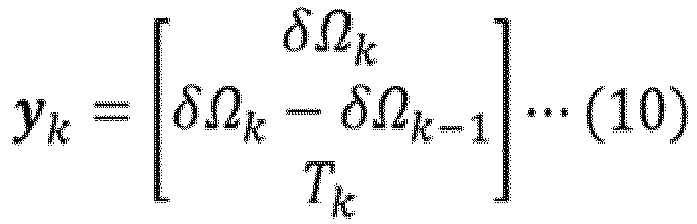
- The observation equation is defined by Equation (11). In Equation (11), Hk is the observation Jacobian, and is expressed by Equation (12). In addition, in Equation (11), wk is observation noise, and has, as its elements, σw1, σw2, and σw3 that are set to appropriate values in advance as shown in Equation (13).


- The temperature
characteristic estimation unit 60 executes a prediction step, an observation step, and an update step of the extended Kalman filter, and estimates the temperature characteristic of the angular velocity bias δΩk. - First, in the prediction step, the temperature
characteristic estimation unit 60 predicts a state variable x̂k|k-1 at time k from a state variable x̂k-1|k-1 updated in the update step at time k-1 by using Equation (14) based on State Equation (7). That is, the state variable x̂k-1|k-1 is a posteriori estimation value at time k-1, and the state variable x̂k|k-1 is a priori estimation value at time k.
- In addition, in the prediction step, the temperature
characteristic estimation unit 60 predicts, by using Equation (15), the covariance matrix Pk|k-1 of the state variable x̂k|k-1 at time k from the covariance matrix Pk-1|k-1 of the state variable x̂k-1|k-1 updated in the update step at time k-1. In Equation (15), Vk is a covariance matrix of the drive noise vk, and is calculated by Equation (16).

- Subsequently, in the observation step, the temperature
characteristic estimation unit 60 calculates a value to be observed from the state variables x̂k|k-1 predicted in the prediction step at time k by using Equation (17) based on Observation Equation (11). In Equation (17), the temperature change ΔTk is, as in Equation (18), a difference between the temperature Tk|k-1 included in the state variable x̂k|k-1 and the temperature Tk-1|k-1 included in the state variable x̂k-1|k-1. In addition, the temperature change ΔTk-1 is, as in Equation (19), a difference between the temperature Tk-1|k-1 included in the state variable x̂k-1|k-1 and the temperature Tk-2|k-2 included in the state variable x̂k-2|k-2.


- The temperature
characteristic estimation unit 60 calculates, by using Equation (20), an observation residual ek, which is a difference between the value of the observation variable yk at time k of actual observation and the value calculated by Equation (17).
- In addition, in the observation step, the temperature
characteristic estimation unit 60 calculates, by using Equation (21), the covariance matrix Sk of the observation residual ek from the covariance matrix Pk|k-1 of the state variable x̂k|k-1 predicted in the prediction step at time k. In Equation (21), Wk is a covariance matrix of the observation noise wk, and is calculated by Equation (22). In addition, Hk is an observation Jacobian matrix, and is calculated by Equation (23).


- Finally, in the update step, the temperature
characteristic estimation unit 60 calculates, by using Equation (24), a Kalman gain Kk from the covariance matrix Pk|k-1 of the state variable x̂k|k-1 predicted in the prediction step at time k and the covariance matrix Sk of the observation residual ek calculated in the observation step at time k.
- In the update step, the temperature
characteristic estimation unit 60 updates, by using Equation (25), the state variable x̂k|k-1 predicted in the prediction step at time k to the state variable x̂k|k, based on the Kalman gain Kk and the observation residual ek calculated in the observation step at time k. As described above, the state variable x̂k|k-1 is a priori estimation value at time k. In addition, the state variable x̂k|k is a posteriori estimation value at time k.
- Thus, the temperature
characteristic estimation unit 60 estimates, by using the extended Kalman filter, the first-order coefficient c1,k and the zero-order coefficient c0,k included in the state variables xk. - In the update step, the temperature
characteristic estimation unit 60 updates, by using Equation (26), the covariance matrix Pk|k-1 of the state variables x̂k|k-1 predicted in the prediction step at time k to the covariance matrix Pk|k of the state variables x̂k|k, based on the Kalman gains Kk.
- In the covariance matrix Pk|k, p11 is the variance of the first-order coefficient c1,k and p22 is the variance of the zero-order coefficient c0,k. In a case in which the temperature
characteristic information 71 includes the value of the first-order coefficient c1,k for the temperature Tk, the temperaturecharacteristic estimation unit 60 updates the value of the first-order coefficient c1,k included in the temperaturecharacteristic information 71 to the estimated value of the first-order coefficient c1,k when the variance p11 is equal to or less than a predetermined threshold value and does not update the value of the first-order coefficient c1,k included in the temperaturecharacteristic information 71 when the variance p11 is larger than the predetermined threshold value. When the temperaturecharacteristic information 71 does not include the value of the first-order coefficient c1,k for the temperature Tk, the temperaturecharacteristic estimation unit 60 updates the value of the first-order coefficient c1,k included in the temperaturecharacteristic information 71 to the estimated value of the first-order coefficient c1,k regardless of the value of the variance p11. - Similarly, in a case in which the temperature
characteristic information 71 includes the value of the zero-order coefficient c0,k for the temperature Tk, the temperaturecharacteristic estimation unit 60 updates the value of the zero-order coefficient c0,k included in the temperaturecharacteristic information 71 to the estimated value of the zero-order coefficient c0,k when the variance p22 is equal to or less than a predetermined threshold value and does not update the value of the zero-order coefficient c0,k included in the temperaturecharacteristic information 71 when the variance p22 is larger than the predetermined threshold value. When the temperaturecharacteristic information 71 does not include the value of the zero-order coefficient c0,k for the temperature Tk, the temperaturecharacteristic estimation unit 60 updates the value of the zero-order coefficient c0,k included in the temperaturecharacteristic information 71 to the estimated value of the zero-order coefficient c0,k regardless of the value of the variance p22. - The angular velocity
bias prediction unit 50 predicts the angular velocity bias δΩk based on the temperature Tk detected by thetemperature sensor 15 and the temperaturecharacteristic information 71 stored in thestorage unit 70. For example, the angular velocitybias prediction unit 50 may predict the angular velocity bias δΩk by substituting the temperature Tk-1, the temperature Tk, and the coefficient c0,k to cn,k for the temperature Tk included in the temperaturecharacteristic information 71 into the polynomial (4). - The
azimuth calculation device 1 configured as described above can estimate the angular velocity bias δΩk at a predetermined period, for example, every one second, regardless of whether thevehicle 5 as a moving body is stopped or traveling, and calculate the highly accurate third azimuth Ψest,k with the angular velocity bias corrected. - A person who manufactures the
angular velocity sensor 13 or a place where theangular velocity sensor 13 is manufactured may be the same as or different from a person who modularizes a part or entirety of theazimuth calculation device 1 including theangular velocity sensor 13 or a place where a part or entirety of theazimuth calculation device 1 including theangular velocity sensor 13 is modularized. -
FIG. 5 is a flowchart illustrating an example of the procedure of an azimuth calculation method according to the present embodiment. As illustrated inFIG. 5 , the azimuth calculation method according to the present embodiment includes a first azimuth calculation step S10, a second azimuth calculation step S20, a third azimuth calculation step S30, a temperature characteristic estimation step S40, and an angular velocity bias prediction step S50. In the present embodiment, theazimuth calculation device 1 performs processing of each step according to the procedure illustrated inFIG. 5 . Theazimuth calculation device 1 may perform the processing of each step by executing a program (not shown). - First, in the first azimuth calculation step S10, the first
azimuth calculation unit 20 of theazimuth calculation device 1 calculates the first azimuth Ψgnss,k based on the satellite signal received by thesatellite signal receiver 11. - Subsequently, in the second azimuth calculation step S20, the second
azimuth calculation unit 30 of theazimuth calculation device 1 calculates the second azimuth Ψins,k based on the angular velocity signal output from theangular velocity sensor 13 detecting the angular velocity. The secondazimuth calculation unit 30 calculates the second azimuth Ψins,k with the angular velocity bias corrected, based on the angular velocity bias δΩk-1 last time predicted in the angular velocity bias prediction step S50 to be described later. - Subsequently, in the third azimuth calculation step S30, the third
azimuth calculation unit 40 of theazimuth calculation device 1 calculates the third azimuth Ψest,k based on the first azimuth Ψgnss,k calculated in the first azimuth calculation step S10 and the second azimuth Ψins,k calculated in the second azimuth calculation step S20. - Subsequently, in the temperature characteristic estimation step S40, the temperature
characteristic estimation unit 60 of theazimuth calculation device 1 estimates, based on the second azimuth Ψins,k calculated in the second azimuth calculation step S20 and the third azimuth Ψest,k calculated in the third azimuth calculation step S30, the temperature characteristic of the angular velocity biases δΩk for the temperature Tk detected by thetemperature sensors 15, and updates, based on the estimated temperature characteristic, the temperaturecharacteristic information 71 of the angular velocity bias δΩk stored in thestorage unit 70. - The temperature
characteristic estimation unit 60 estimates the values of the coefficients c0,k to cn,k of the polynomial (4) as the temperature characteristic of the angular velocity bias δΩk, calculates the variance of the estimated coefficients c0,k to cn,k. In a case in which the temperaturecharacteristic information 71 includes the value of the coefficient ci,k for the temperature Tk, the temperaturecharacteristic estimation unit 60 may update the value of the coefficient ci,k included in the temperaturecharacteristic information 71 to the estimated value of the coefficient ci,k when the variance of the coefficient ci,k is equal to or less than a predetermined threshold value and may not update the value of the coefficient ci,k included in the temperaturecharacteristic information 71 when the variance of the coefficient ci,k is larger than the predetermined threshold value. - Subsequently, in the angular velocity bias prediction step S50, the angular velocity
bias prediction unit 50 of theazimuth calculation device 1 predicts the angular velocity bias δΩk based on the temperature Tk detected by thetemperature sensor 15 and the temperaturecharacteristic information 71 stored in thestorage unit 70. - The
azimuth calculation device 1 repeatedly performs steps S10 to S50 until the azimuth calculation process ends in step S60. -
FIG. 6 is a flowchart illustrating an example of the specific procedure of an azimuth calculation method according to a first embodiment. - As illustrated in
FIG. 6 , first, in step S1, theazimuth calculation device 1 initializes time k to 0. - Subsequently, when the
satellite signal receiver 11 can receive a satellite signal in step S2, the firstazimuth calculation unit 20 of theazimuth calculation device 1 calculates the first azimuth Ψgnss,k based on the satellite signal received by thesatellite signal receiver 11 in step S11. When thesatellite signal receiver 11 cannot receive a satellite signal in step S2, the firstazimuth calculation unit 20 does not perform the processing of step S11. Step S11 corresponds to the first azimuth calculation step S10 inFIG. 5 . - Subsequently, in step S21, the second
azimuth calculation unit 30 of theazimuth calculation device 1 sets the initial value of the second azimuth Ψins,k. Specifically, the third azimuth Ψest,k-1 last time calculated in step S31 described later is set as the initial value of the second azimuth Ψins,k. When the third azimuth Ψest,k-1 is not calculated last time in step S31, the secondazimuth calculation unit 30 sets the second azimuth Ψins,k-1 last time calculated in step S23, which will be described later, as the initial value of the second azimuth Ψins,k. When time k is 0, the secondazimuth calculation unit 30 sets the second azimuth Ψins,k to an appropriate initial value. - Subsequently, in step S22, the second
azimuth calculation unit 30 calculates, by using Equation (1) above, the angular velocity of the yaw angle ψ based on the angular velocity ωz,k around the Z-axis detected by theangular velocity sensor 13, and corrects the bias of the angular velocity of the yaw angle ψ by subtracting the angular velocity bias δΩk-1 last time predicted in step S51, which will be described later, from the angular velocity of the yaw angle ψ. - Subsequently, in step S23, a value obtained by integrating the angular velocity of the yaw angle ψ whose bias has been corrected in step S21 is added to the initial value of the second azimuth Ψins,k set in step S22 to calculate the second azimuth Ψins,k with the angular velocity bias corrected.
- Steps S21, S22, and S23 correspond to the second azimuth calculation step S20 in
FIG. 5 . - Subsequently, when it is determined in step S28 that the first azimuth Ψgnss,k has been calculated in step S11, in step S31, the third
azimuth calculation unit 40 of theazimuth calculation device 1 calculates the third azimuth Ψest,k based on the first azimuth ψgnss,k calculated in step S11 and the second azimuth Ψins,k calculated in step S23. In step S30, when the first azimuth Ψgnss,k is not calculated in step S11, the thirdazimuth calculation unit 40 does not perform the processing of step S31. Step S31 corresponds to the third azimuth calculation step S30 inFIG. 5 . - Subsequently, in step S41, the temperature
characteristic estimation unit 60 of theazimuth calculation device 1 calculates, by using Equation (3) above, an error δΨins,k of the second azimuth Ψins,k. - Subsequently, in step S42, the temperature
characteristic estimation unit 60 calculates, by using Equation (2) above, the angular velocity bias δΩk, which is the bias of the angular velocity of the second azimuth Ψins,k. - Subsequently, in step S43, the temperature
characteristic estimation unit 60 calculates the temperature characteristic of the angular velocity bias δΩk. Specifically, the temperaturecharacteristic estimation unit 60 calculates the observation variable yk shown in Equation (10) above based on the angular velocity bias δΩk calculated in step S42 and the temperature Tk detected by thetemperature sensor 15, and calculates, by using the extended Kalman filter described above, the state variable xk having, as its elements, the first-order coefficient c1,k, the zero-order coefficient c0,k, and the temperature Tk of the above polynomial (5) shown in Equation (6) above. - Subsequently, in step S44, the temperature
characteristic estimation unit 60 updates the temperaturecharacteristic information 71 stored in thestorage unit 70. Specifically, the temperaturecharacteristic estimation unit 60 calculates the covariance matrix Pk|k shown in Equation (26) above. - Subsequently, in a case in which the temperature
characteristic information 71 includes the value of the first-order coefficient c1,k for the temperature Tk, the temperaturecharacteristic estimation unit 60 updates the value of the coefficient c1,k included in the temperaturecharacteristic information 71 to the estimated value of the coefficient c1,k when the variance p11 is equal to or less than a predetermined threshold value and does not update the value of the coefficient c1,k included in the temperaturecharacteristic information 71 when the variance p11 is larger than the predetermined threshold value. When the temperaturecharacteristic information 71 does not include the value of the first-order coefficient c1,k for the temperature Tk, the temperaturecharacteristic estimation unit 60 updates the value of the first-order coefficient c1,k included in the temperaturecharacteristic information 71 to the estimated value of the first-order coefficient c1,k regardless of the value of the variance p11. - Similarly, in a case in which the temperature
characteristic information 71 includes the value of the zero-order coefficient c0,k for the temperature Tk, the temperaturecharacteristic estimation unit 60 updates the value of the zero-order coefficient c0,k included in the temperaturecharacteristic information 71 to the estimated value of the zero-order coefficient c0,k when the variance p22 is equal to or less than a predetermined threshold value and does not update the value of the zero-order coefficient c0,k included in the temperaturecharacteristic information 71 when the variance p22 is larger than the predetermined threshold value. When the temperaturecharacteristic information 71 does not include the value of the zero-order coefficient c0,k for the temperature Tk, the temperaturecharacteristic estimation unit 60 updates the value of the zero-order coefficient c0,k included in the temperaturecharacteristic information 71 to the estimated value of the zero-order coefficient c0,k regardless of the value of the variance p22. - Steps S41, S42, S43, and S44 correspond to the temperature characteristic estimation step S40 in
FIG. 5 . - Subsequently, in step S51, the angular velocity
bias prediction unit 50 of theazimuth calculation device 1 predicts the angular velocity bias δΩk of the second azimuth Ψins,k based on the temperaturecharacteristic information 71 stored in thestorage unit 70. For example, the angular velocitybias prediction unit 50 may predict the angular velocity bias δΩk by substituting the temperature Tk-1, the temperature Tk, and the first-order coefficient c1,k and the zero-order coefficient c0,k for the temperature Tk included in the temperaturecharacteristic information 71 into the linear polynomial (5). Step S51 corresponds to the angular velocity bias prediction step S50 inFIG. 5 . - The
azimuth calculation device 1 increases time k by 1 in step S58, and repeatedly performs steps S2 to S58 until the azimuth calculation process ends in step S60. - In this manner, the
azimuth calculation device 1 can estimate the angular velocity bias δΩk at a predetermined period, for example, every one second, regardless of whether thevehicle 5 as a moving body is stopped or traveling, and calculate the highly accurate third azimuth Ψest,k with the angular velocity bias corrected. - As described above, in the first embodiment, the first
azimuth calculation unit 20 can calculate the first azimuth Ψgnss,k based on the satellite signal regardless of whether the moving body on which theazimuth calculation device 1 is mounted is stopped or traveling, and the secondazimuth calculation unit 30 can calculate the second azimuth Ψins,k based on the angular velocity signal output from theangular velocity sensor 13 even when a satellite signal cannot be received. Therefore, the thirdazimuth calculation unit 40 can seamlessly and periodically calculate the third azimuth Ψest,k based on the first azimuth Ψgnss,k and the second azimuth Ψins,k. As a result, even when the moving body is traveling, the temperaturecharacteristic estimation unit 60 can periodically estimate the temperature characteristic of the angular velocity bias δΩk of the second azimuth Ψins,k based on the second azimuth Ψins,k and the third azimuth Ψest,k and can update the temperaturecharacteristic information 71 stored in thestorage unit 70. Therefore, the secondazimuth calculation unit 30 can calculate the second azimuth Ψins,k with the angular velocity bias corrected, based on the angular velocity bias δΩk-1 last time predicted by the angular velocitybias prediction unit 50 based on the temperaturecharacteristic information 71. In addition, since the temperaturecharacteristic estimation unit 60 estimates the temperature characteristic of the angular velocity bias δΩk for the temperature Tk detected by thetemperature sensor 15, it is possible to accurately estimate the temperature characteristic of the angular velocity bias δΩk for each narrow temperature range. Therefore, according to the first embodiment, theazimuth calculation device 1 can calculate the azimuth with the angular velocity bias corrected with high accuracy regardless of whether the moving body is stopped or traveling. - In addition, in the first embodiment, the angular velocity bias δΩk is not approximated by a polynomial having the temperature Tk as a variable, but is approximated by the polynomial (4) having the temperature change ΔTk as a variable. Therefore, the temperature
characteristic estimation unit 60 can accurately estimate the temperature characteristic of the angular velocity bias δΩk for each narrow temperature range. In a narrow temperature range, the angular velocity bias δΩk is accurately approximated by the linear polynomial (5) having the temperature change ΔTk as a variable. Therefore, it is possible to reduce the calculation load for estimation while maintaining the estimation accuracy of the temperature characteristic of the angular velocity bias δΩk by the temperaturecharacteristic estimation unit 60. - In addition, in the first embodiment, since the temperature
characteristic estimation unit 60 updates the values of the coefficients c0,k to cn,k included in the temperaturecharacteristic information 71 only when the estimation accuracy of the coefficients c0,k to cn,k of the polynomial (4) approximating the angular velocity bias δΩk is equal to or greater than a predetermined value, the angular velocitybias prediction unit 50 can accurately predict the angular velocity bias δΩk based on the temperaturecharacteristic information 71. Therefore, according to the first embodiment, theazimuth calculation device 1 can calculate the azimuth with the angular velocity bias corrected with high accuracy. - Hereinafter, in a second embodiment, components similar to those in the first embodiment are denoted by the same reference numerals, descriptions overlapping those in the first embodiment will be omitted or simplified, and contents different from those in the first embodiment will be mainly described.
- In the second embodiment, the angular velocity bias δΩk is different from that in the first embodiment. That is, in the first embodiment, the angular velocity bias δΩk is the bias of the angular velocity of the second azimuth Ψins,k calculated by the second
azimuth calculation unit 30. However, in the second embodiment, the angular velocity bias δΩk is the bias of the angular velocity ωz,k around the Z-axis detected by theangular velocity sensor 13. Since the Z-axis corresponds to the yaw axis, the angular velocity bias δΩk is, in other words, the bias of the angular velocity ωz,k around the yaw axis. - Since a configuration example of an
azimuth calculation device 1 according to the second embodiment is the same as that inFIG. 1 , illustration thereof will be omitted. However, in theazimuth calculation device 1 according to the second embodiment, processes performed by the secondazimuth calculation unit 30, the angular velocitybias prediction unit 50, and the temperaturecharacteristic estimation unit 60 are different from those in the first embodiment. - The second
azimuth calculation unit 30 calculates a second azimuth Ψins,k, which is the azimuth of the moving body in the global coordinate system at time k, based on the angular velocity signal output from theangular velocity sensor 13. The secondazimuth calculation unit 30 calculates the second azimuth Ψins,k at time k with the angular velocity bias corrected, based on the angular velocity bias δΩk-1 at the last time k-1 predicted by the angular velocitybias prediction unit 50. Specifically, the secondazimuth calculation unit 30 calculates the angular velocity around the Z-axis with the angular velocity bias corrected by subtracting the angular velocity bias δΩk-1 from the angular velocity ωz,k around the Z-axis detected by theangular velocity sensor 13. With the third azimuth Ψest,k-1 at the last time k-1 calculated by the thirdazimuth calculation unit 40 as the initial azimuth, the secondazimuth calculation unit 30 calculates the second azimuth Ψins,k at time k by adding, to the third azimuth Ψest,k-1, a value, which is obtained by integrating the angular velocity of the yaw angle ψ obtained by substituting the angular velocity around the Z-axis into Equation (1). - The temperature
characteristic estimation unit 60 estimates the temperature characteristic of the angular velocity bias δΩk for the temperature Tk detected by thetemperature sensor 15, based on the second azimuth Ψins,k calculated by the secondazimuth calculation unit 30 and the third azimuth Ψest,k calculated by the thirdazimuth calculation unit 40, and updates, based on the estimated temperature characteristic, the temperaturecharacteristic information 71 stored in thestorage unit 70. - In the present embodiment, the temperature
characteristic estimation unit 60 calculates, by using Equation (27), the angular velocity bias δΩk, which is an element of the observation variable yk shown in Equation (10) above.
- The temperature
characteristic estimation unit 60 calculates, by Equation (28), the angular velocity ωest z,k included in Equation (27), using the third azimuth Ψest,k, the roll angle Φest,k, and the pitch angle Θest,k calculated by the thirdazimuth calculation unit 40. In Equation (29), ΔΘest,k and ΔΨest,k are expressed by Equation (29) and Equation (30), respectively.


- The temperature
characteristic estimation unit 60 estimates the first-order coefficient c1,k and the zero-order coefficient c0,k of the linear polynomial (5) for the temperature Tk by using the extended Kalman filter similar to that in the first embodiment. - The angular velocity
bias prediction unit 50 predicts the angular velocity bias δΩk based on the temperature Tk detected by thetemperature sensor 15 and the temperaturecharacteristic information 71 stored in thestorage unit 70. For example, the angular velocitybias prediction unit 50 may predict the angular velocity bias δΩk by substituting the temperature Tk-1, the temperature Tk, and the coefficient c0,k to cn,k for the temperature Tk included in the temperaturecharacteristic information 71 into the above polynomial (4). - The other configurations and functions of the
azimuth calculation device 1 according to the second embodiment are the same as those in the first embodiment, and accordingly, description thereof will be omitted. - A flowchart illustrating an example of the procedure of an azimuth calculation method according to the second embodiment is the same as
FIG. 5 , and accordingly, illustration and description thereof will be omitted. However, in the second embodiment, specific procedures of the second azimuth calculation step S20, the temperature characteristic estimation step S40, and the angular velocity bias prediction step S50 inFIG. 5 are different from those in the first embodiment.FIG. 7 is a flowchart illustrating an example of the specific procedure of an azimuth calculation method according to a second embodiment. InFIG. 7 , the same steps as those inFIG. 6 are denoted by the same reference numerals. - As illustrated in
FIG. 7 , first, in step S1, theazimuth calculation device 1 initializes time k to 0. - Subsequently, when the
satellite signal receiver 11 can receive a satellite signal in step S2, the firstazimuth calculation unit 20 of theazimuth calculation device 1 calculates, in step S11, the first azimuth Ψgnss,k based on the satellite signal received by thesatellite signal receiver 11. When thesatellite signal receiver 11 cannot receive a satellite signal in step S2, the firstazimuth calculation unit 20 does not perform the processing of step S11. Step S11 corresponds to the first azimuth calculation step S10 inFIG. 5 . - Subsequently, in step S21, the second
azimuth calculation unit 30 of theazimuth calculation device 1 sets the initial value of the second azimuth Ψins,k. Specifically, the third azimuth Ψest,k-1 last time calculated in step S31 described later is set as the initial value of the second azimuth Ψins,k. When the third azimuth Ψest,k-1 is not calculated last time in step S31, the secondazimuth calculation unit 30 sets the second azimuth Ψins,k-1 last time calculated in step S23a, which will be described later, as the initial value of the second azimuth Ψins,k. When time k is 0, the secondazimuth calculation unit 30 sets the second azimuth Ψins,k to an appropriate initial value. - Subsequently, in step S22a, the second
azimuth calculation unit 30 corrects the angular velocity bias around the yaw axis by subtracting the angular velocity bias δΩk-1 last time predicted in step S51a, which will be described later, from the angular velocity ωz,k around the Z-axis detected by theangular velocity sensor 13. - Subsequently, in step S23a, the second
azimuth calculation unit 30 adds, to the initial value of the second azimuth Ψins,k set in step S21, a value obtained by integrating the angular velocity of the yaw angle ψ obtained by substituting the angular velocity around the yaw axis whose bias has been corrected in step S22a into Equation (1) above to calculate the second azimuth Ψins,k. - Steps S21, S22a, and S23a correspond to the second azimuth calculation step S20 in
FIG. 5 . - Subsequently, when it is determined in step S28 that the first azimuth Ψgnss,k has been calculated in step S11, the third
azimuth calculation unit 40 of theazimuth calculation device 1 calculates, in step S31, the third azimuth Ψest,k based on the first azimuth Ψgnss,k calculated in step S11 and the second azimuth Ψins,k calculated in step S23a. In step S30, when the first azimuth Ψgnss,k is not calculated in step S11, the thirdazimuth calculation unit 40 does not perform the processing of step S31. In step S31, the thirdazimuth calculation unit 40 also calculates the roll angle Φest,k and the pitch angle Θest,k. Step S31 corresponds to the third azimuth calculation step S30 inFIG. 5 . - Subsequently, in step S41, the temperature
characteristic estimation unit 60 of theazimuth calculation device 1 calculates an error δΨins,k of the second azimuth Ψins,k by using Equation (3) above. - Subsequently, in step S42a, the temperature
characteristic estimation unit 60 calculates the angular velocity bias δΩk, which is the bias of the angular velocity ωz,k around the yaw axis, by using Equation (27) above. - Subsequently, in step S43a, the temperature
characteristic estimation unit 60 calculates the temperature characteristic of the angular velocity bias δΩk. Specifically, the temperaturecharacteristic estimation unit 60 calculates the observation variable yk shown in Equation (10) above based on the angular velocity bias δΩk calculated in step S42a and the temperature Tk detected by thetemperature sensor 15, and calculates the state variable xk having, as its elements, the first-order coefficient c1,k, the zero-order coefficient c0,k, and the temperature Tk of the above polynomial (5) shown in Equation (6) above by using the extended Kalman filter described above. - Subsequently, in step S44a, the temperature
characteristic estimation unit 60 updates the temperaturecharacteristic information 71 stored in thestorage unit 70. Specifically, the temperaturecharacteristic estimation unit 60 calculates the covariance matrix Pk|k shown in Equation (26) above. - In a case in which the temperature
characteristic information 71 includes the value of the first-order coefficient c1,k for the temperature Tk, the temperaturecharacteristic estimation unit 60 updates the value of the coefficient c1,k included in the temperaturecharacteristic information 71 to the estimated value of the coefficient c1,k when the variance p11 is equal to or less than a predetermined threshold value and does not update the value of the coefficient c1,k included in the temperaturecharacteristic information 71 when the variance p11 is larger than the predetermined threshold value. When the temperaturecharacteristic information 71 does not include the value of the first-order coefficient c1,k for the temperature Tk, the temperaturecharacteristic estimation unit 60 updates the value of the first-order coefficient c1,k included in the temperaturecharacteristic information 71 to the estimated value of the first-order coefficient c1,k regardless of the value of the variance p11. - Similarly, in a case in which the temperature
characteristic information 71 includes the value of the zero-order coefficient c0,k for the temperature Tk, the temperaturecharacteristic estimation unit 60 updates the value of the zero-order coefficient c0,k included in the temperaturecharacteristic information 71 to the estimated value of the zero-order coefficient c0,k when the variance p22 is equal to or less than a predetermined threshold value and does not update the value of the zero-order coefficient c0,k included in the temperaturecharacteristic information 71 when the variance p22 is larger than the predetermined threshold value. When the temperaturecharacteristic information 71 does not include the value of the zero-order coefficient c0,k for the temperature Tk, the temperaturecharacteristic estimation unit 60 updates the value of the zero-order coefficient c0,k included in the temperaturecharacteristic information 71 to the estimated value of the zero-order coefficient c0,k regardless of the value of the variance p22. - Steps S41, S42a, S43a, and S44a correspond to the temperature characteristic estimation step S40 in
FIG. 5 . - Subsequently, in step S51a, the angular velocity
bias prediction unit 50 of theazimuth calculation device 1 predicts the angular velocity bias δΩk around the yaw axis based on the temperaturecharacteristic information 71 stored in thestorage unit 70. For example, the angular velocitybias prediction unit 50 may predict the angular velocity bias δΩk by substituting the temperature Tk-1, the temperature Tk, and the first-order coefficient c1,k and the zero-order coefficient c0,k for the temperature Tk included in the temperaturecharacteristic information 71 into the linear polynomial (5). Step S51a corresponds to the angular velocity bias prediction step S50 inFIG. 5 . - The
azimuth calculation device 1 increases time k by 1 in step S58, and repeatedly performs steps S2 to S58 until the azimuth calculation process ends in step S60. - As described above, in the second embodiment, even when the moving body is traveling, the temperature
characteristic estimation unit 60 can periodically estimate, based on the second azimuth Ψins,k and the third azimuth Ψest,k, the temperature characteristic of the angular velocity bias δΩk of the angular velocity ωz,k around the yaw axis detected by theangular velocity sensor 13 and can update the temperaturecharacteristic information 71 stored in thestorage unit 70. Therefore, the secondazimuth calculation unit 30 can calculate the second azimuth Ψins,k with the angular velocity bias corrected, based on the angular velocity bias δΩk-1 last time predicted by the angular velocitybias prediction unit 50 based on the temperaturecharacteristic information 71. Therefore, according to the second embodiment, theazimuth calculation device 1 can calculate the azimuth with the angular velocity bias corrected with high accuracy regardless of whether the moving body is stopped or traveling. In addition, according to the second embodiment, the same effects as those in the first embodiment can be obtained. - Hereinafter, in a third embodiment, components similar to those in the first embodiment or the second embodiment are denoted by the same reference numerals, descriptions overlapping those in the first embodiment or the second embodiment will be omitted or simplified, and contents different from those in the first and second embodiments will be mainly described.
-
FIG. 8 is a diagram illustrating a configuration example of anazimuth calculation device 1 according to the third embodiment. InFIG. 8 , the same components as those inFIG. 1 are denoted by the same reference numerals. As illustrated inFIG. 8 , theazimuth calculation device 1 according to the third embodiment includes, similarly to the first embodiment, a firstazimuth calculation unit 20, a secondazimuth calculation unit 30, a thirdazimuth calculation unit 40, an angular velocitybias prediction unit 50, a temperaturecharacteristic estimation unit 60, and astorage unit 70. Theazimuth calculation device 1 may include awheel speed sensor 12, anangular velocity sensor 13, a6DoF sensor 14, atemperature sensor 15, and anexternal sensor 16. Theazimuth calculation device 1 may have a configuration in which some of the components inFIG. 8 are omitted or changed or other components are added. - The third embodiment is different from the first and second embodiments in that the first
azimuth calculation unit 20 performs processing using theexternal sensor 16 instead of thesatellite signal receiver 11. - The
external sensor 16 is a sensor that detects information around the moving body, and may be, for example, a LiDAR, a camera, and a millimeter wave radar that are used for AD, ADAS, and the like. AD is an abbreviation for autonomous driving, and ADAS is an abbreviation for advanced driver assistance system. LiDAR is an abbreviation for light detection and ranging or laser imaging detection and ranging. - The first
azimuth calculation unit 20 calculates a first azimuth ΨEXT,k, which is the azimuth of the moving body in the global coordinate system at time k, based on the detection result of theexternal sensor 16. The firstazimuth calculation unit 20 calculates the first azimuth ΨEXT,k at a predetermined period, for example, every one second. For example, the firstazimuth calculation unit 20 calculates the first azimuth ΨEXT,k, which is the azimuth of the moving body in the global coordinate system, by comparing the information around the moving body, which is the detection result of theexternal sensor 16, withmap information 72 stored in thestorage unit 70. The firstazimuth calculation unit 20 may further calculate the position or the speed of the moving body in the global coordinate system. - As in the first embodiment or the second embodiment, the second
azimuth calculation unit 30 calculates, based on the angular velocity signal output from theangular velocity sensor 13, the second azimuth Ψins,k, which is the azimuth of the moving body in the global coordinate system at time k. The secondazimuth calculation unit 30 calculates the second azimuth Ψins,k at time k with the angular velocity bias corrected, based on the angular velocity bias δΩk-1 at the last time k-1 predicted by the angular velocitybias prediction unit 50. - The third
azimuth calculation unit 40 calculates the third azimuth Ψest,k, which is the azimuth of the moving body in the global coordinate system at time k, based on the first azimuth ΨEXT,k at time k calculated by the firstazimuth calculation unit 20 and the second azimuth Ψins,k at time k calculated by the secondazimuth calculation unit 30. The thirdazimuth calculation unit 40 calculates the third azimuth Ψest,k at a predetermined period, for example, every one second. For example, the thirdazimuth calculation unit 40 may set the first azimuth ΨEXT,k as the third azimuth Ψest,k at the timing when the first azimuth ΨEXT,k is calculated, and may set the second azimuth Ψins,k as the third azimuth Ψest,k at the timing when the first azimuth ΨEXT,k is not calculated. In addition, the thirdazimuth calculation unit 40 may calculate the third azimuth Ψest,k by using a Kalman filter. - As in the first embodiment or the second embodiment, the
storage unit 70 stores the temperaturecharacteristic information 71 of the angular velocity bias δΩk. The angular velocity bias δΩk may be a bias of the angular velocity of the second azimuth Ψins,k calculated by the secondazimuth calculation unit 30, as illustrated in Equation (2) above. In addition, the angular velocity bias δΩk may be a bias of the angular velocity ωz,k around the yaw axis detected by theangular velocity sensor 13, as illustrated in Equation (27) above. In addition, in the third embodiment, thestorage unit 70 stores themap information 72 used for calculation of the first azimuth ΨEXT,k by the firstazimuth calculation unit 20. - As in the first embodiment or the second embodiment, the temperature
characteristic estimation unit 60 estimates the temperature characteristic of the angular velocity bias δΩk for the temperature Tk detected by thetemperature sensor 15, based on the second azimuth Ψins,k calculated by the secondazimuth calculation unit 30 and the third azimuth Ψest,k calculated by the thirdazimuth calculation unit 40, and updates the temperaturecharacteristic information 71 stored in thestorage unit 70, based on the estimated temperature characteristic. As described above, the temperaturecharacteristic estimation unit 60 may estimate the first-order coefficient c1,k and the zero-order coefficient c0,k for the temperature Tk by using an extended Kalman filter. - As in the first embodiment or the second embodiment, the angular velocity
bias prediction unit 50 predicts the angular velocity bias δΩk based on the temperature Tk detected by thetemperature sensor 15 and the temperaturecharacteristic information 71 stored in thestorage unit 70. As described above, the angular velocitybias prediction unit 50 may predict the angular velocity bias δΩk by substituting the temperature Tk-1, the temperature Tk, and the coefficient c0,k to cn,k for the temperature Tk included in the temperaturecharacteristic information 71 into the above polynomial (4). - The other configurations and functions of the
azimuth calculation device 1 according to the third embodiment are the same as those of theazimuth calculation device 1 according to the first embodiment or the second embodiment, and accordingly, description thereof will be omitted. - A flowchart illustrating an example of the procedure of an azimuth calculation method according to the third embodiment is the same as
FIG. 5 , and accordingly, illustration thereof will be omitted. In the third embodiment, in the first azimuth calculation step S10 inFIG. 5 , the firstazimuth calculation unit 20 of theazimuth calculation device 1 calculates the first azimuth ΨEXT,k based on the detection result of theexternal sensor 16. The processing from the second azimuth calculation step S20 inFIG. 5 , which is performed by theazimuth calculation device 1, is the same as that in the first embodiment or the second embodiment except that the first azimuth ΨEXT,k is used instead of the first azimuth Ψgnss,k, and accordingly, description thereof will be omitted. -
FIG. 9 is a flowchart illustrating an example of the specific procedure of the azimuth calculation method according to the third embodiment. InFIG. 9 , the same steps as those inFIG. 6 are denoted by the same reference numerals. InFIG. 9 , the angular velocity bias δΩk is the bias of the angular velocity of the second azimuth Ψins,k. - As illustrated in
FIG. 9 , first, in step S1, theazimuth calculation device 1 initializes time k to 0. - Subsequently, in step S12, the first
azimuth calculation unit 20 of theazimuth calculation device 1 calculates the first azimuth ΨEXT,k based on the detection result of theexternal sensor 16. Step S12 corresponds to the first azimuth calculation step S10 inFIG. 5 . - Subsequently, in steps S21, S22, and S23, the second
azimuth calculation unit 30 of theazimuth calculation device 1 calculates, by performing the same processing as steps S21, S22, and S23 inFIG. 6 , the second azimuth Ψins,k with the angular velocity bias corrected. Steps S21, S22, and S23 correspond to the second azimuth calculation step S20 inFIG. 5 . - Subsequently, in step S31, the third
azimuth calculation unit 40 of theazimuth calculation device 1 calculates the third azimuth Ψest,k based on the first azimuth ΨEXT,k calculated in step S12 and the second azimuth Ψins,k calculated in step S23. Step S31 corresponds to the third azimuth calculation step S30 inFIG. 5 . - Subsequently, in steps S41, S42, S43, and S44, the temperature
characteristic estimation unit 60 of theazimuth calculation device 1 performs processing similar to that in steps S41, S42, S43, and S44 inFIG. 6 and updates the temperaturecharacteristic information 71 stored in thestorage unit 70. Steps S41, S42, S43, and S44 correspond to the temperature characteristic estimation step S40 inFIG. 5 . - Subsequently, in step S51, the angular velocity
bias prediction unit 50 of the azimuth calculation device 1performs processing similar to that in step S51 inFIG. 6 and predicts the angular velocity bias δΩk of the second azimuth Ψins,k. - The
azimuth calculation device 1 increases time k by 1 in step S58, and repeatedly performs steps S2 to S58 until the azimuth calculation process ends in step S60. -
FIG. 10 is a flowchart illustrating another example of the specific procedure of the azimuth calculation method according to the third embodiment. InFIG. 10 , the same steps as those inFIG. 7 are denoted by the same reference numerals. InFIG. 10 , the angular velocity bias δΩk may be the bias of the angular velocity ωz,k around the yaw axis detected by theangular velocity sensor 13. - As illustrated in
FIG. 10 , first, in step S1, theazimuth calculation device 1 initializes time k to 0. - Subsequently, in step S12, the first
azimuth calculation unit 20 of theazimuth calculation device 1 calculates the first azimuth ΨEXT,k based on the detection result of theexternal sensor 16. Step S12 corresponds to the first azimuth calculation step S10 inFIG. 5 . - Subsequently, in steps S21, S22a, and S23a, the second
azimuth calculation unit 30 of theazimuth calculation device 1 performs processing similar to that in steps S21, S22a, and S23a inFIG. 7 and calculates the second azimuth Ψins,k with the angular velocity bias corrected. Steps S21, S22a, and S23a correspond to the second azimuth calculation step S20 inFIG. 5 . - Subsequently, in step S31, the third
azimuth calculation unit 40 of theazimuth calculation device 1 calculates the third azimuth Ψest,k based on the first azimuth ΨEXT,k calculated in step S12 and the second azimuth Ψins,k calculated in step S23a. Step S31 corresponds to the third azimuth calculation step S30 inFIG. 5 . - Subsequently, in steps S41, S42a, S43a, and S44a, the temperature
characteristic estimation unit 60 of theazimuth calculation device 1 performs processing similar to that in steps S41, S42a, S43a, and S44a inFIG. 7 and updates the temperaturecharacteristic information 71 stored in thestorage unit 70. Steps S41, S42a, S43a, and S44a correspond to the temperature characteristic estimation step S40 inFIG. 5 . - Subsequently, in step S51a, the angular velocity
bias prediction unit 50 of theazimuth calculation device 1 performs processing similar to that in step S51a inFIG. 7 and predicts the angular velocity bias δΩk around the yaw axis. - The
azimuth calculation device 1 increases time k by 1 in step S58, and repeatedly performs steps S2 to S58 until the azimuth calculation process ends in step S60. - As described above, in the third embodiment, the first
azimuth calculation unit 20 can calculate the first azimuth ΨEXT,k based on the detection result of theexternal sensor 16 regardless of whether the moving body on which theazimuth calculation device 1 is mounted is stopped or traveling, and the secondazimuth calculation unit 30 can calculate the second azimuth Ψins,k based on the angular velocity signal output from theangular velocity sensor 13. Therefore, the thirdazimuth calculation unit 40 can seamlessly and periodically calculate the third azimuth Ψest,k based on the first azimuth ΨEXT,k and the second azimuth Ψins,k. As a result, even when the moving body is traveling, the temperaturecharacteristic estimation unit 60 can periodically estimate the temperature characteristic of the angular velocity bias δΩk based on the second azimuth Ψins,k and the third azimuth Ψest,k and can update the temperaturecharacteristic information 71 stored in thestorage unit 70. Therefore, the secondazimuth calculation unit 30 can calculate the second azimuth Ψins,k with the angular velocity bias corrected, based on the angular velocity bias δΩk-1 last time predicted by the angular velocitybias prediction unit 50 based on the temperaturecharacteristic information 71. In addition, since the temperaturecharacteristic estimation unit 60 estimates the temperature characteristic of the angular velocity bias δΩk for the temperature Tk detected by thetemperature sensor 15, it is possible to accurately estimate the temperature characteristic of the angular velocity bias δΩk for each narrow temperature range. Therefore, according to the third embodiment, theazimuth calculation device 1 can calculate the azimuth with the angular velocity bias corrected with high accuracy regardless of whether the moving body is stopped or traveling. In addition, according to the third embodiment, the same effects as those in the first embodiment or the second embodiment can be obtained. - The present disclosure is not limited to the present embodiment, and various modifications can be made within the scope of the gist of the present disclosure.
- For example, although an example in which the
azimuth calculation device 1 is mounted on thevehicle 5 has been described in each of the above embodiments, theazimuth calculation device 1 may be mounted on a moving body other than the vehicle Examples of the moving body include not only a vehicle but also an agricultural machine such as a tractor, a construction machine such as an excavator, an unmanned transport vehicle, a robot lawn mower, a robot vacuum cleaner, aircraft such as jet aircraft and helicopter, a ship, a rocket, a satellite, and a railroad vehicle. - In addition, for example, although the
azimuth calculation device 1 includes theangular velocity sensor 13 and the6DoF sensor 14 in each of the above embodiments, theazimuth calculation device 1 may include other sensors instead of these. For example, theazimuth calculation device 1 may include two 6DoF sensors. - The above-described embodiments and modification examples are merely examples, and the present disclosure is not limited thereto. For example, each embodiment and each modification example may be combined as appropriate.
- The present disclosure includes a configuration that is substantially the same as the configuration described in the embodiments, for example, a configuration that has the same function, method, and result, or a configuration that has the same purpose and effect. In addition, the present disclosure includes a configuration in which non-essential portions of the configuration described in the embodiments are replaced. In addition, the present disclosure includes a configuration having the same function and effect as the configuration described in the embodiments or a configuration capable of achieving the same object. In addition, the present disclosure includes a configuration in which a known technique is added to the configuration described in the embodiments.
- The following contents are derived from the above-described embodiments and modification examples.
- An azimuth calculation device according to an aspect of the present disclosure includes: a first azimuth calculation unit that calculates a first azimuth based on a satellite signal received by a satellite signal receiver or a detection result of an external sensor; a second azimuth calculation unit that calculates a second azimuth based on an angular velocity signal output from an angular velocity sensor detecting an angular velocity; a third azimuth calculation unit that calculates a third azimuth based on the first azimuth and the second azimuth; a storage unit that stores temperature characteristic information of an angular velocity bias; a temperature characteristic estimation unit that estimates, based on the second azimuth and the third azimuth, a temperature characteristic of the angular velocity bias for a temperature detected by a temperature sensor and updates, based on the estimated temperature characteristic, the temperature characteristic information stored in the storage unit; and an angular velocity bias prediction unit that predicts the angular velocity bias based on the temperature detected by the temperature sensor and the temperature characteristic information stored in the storage unit. The second azimuth calculation unit calculates, based on the angular velocity bias last time predicted by the angular velocity bias prediction unit, the second azimuth with the angular velocity bias corrected.
- In this azimuth calculation device, the first azimuth calculation unit can calculate the first azimuth based on the satellite signal or the detection result of the external sensor regardless of whether the moving body on which the azimuth calculation device is mounted is stopped or traveling, and the second azimuth calculation unit can calculate the second azimuth based on the angular velocity signal even when a satellite signal cannot be received. Therefore, the third azimuth calculation unit can seamlessly and periodically calculate the third azimuth based on the first azimuth and the second azimuth. As a result, even when the moving body is traveling, the temperature characteristic estimation unit can periodically estimate, based on the second azimuth and the third azimuth, the temperature characteristic of the angular velocity bias and can update the temperature characteristic information. Therefore, the second azimuth calculation unit can calculate the second azimuth with the angular velocity bias corrected, based on the angular velocity bias last time predicted by the angular velocity bias prediction unit based on the temperature characteristic information. In addition, since the temperature characteristic estimation unit estimates the temperature characteristic of the angular velocity bias for the temperature detected by the temperature sensor, it is possible to accurately estimate the temperature characteristic of the angular velocity bias for each narrow temperature range. Therefore, according to this azimuth calculation device, it is possible to calculate the azimuth with the angular velocity bias corrected with high accuracy regardless of whether the moving body is stopped or traveling.
- In the azimuth calculation device according to the aspect of the present disclosure, the angular velocity bias may be approximated by a polynomial having a temperature change as a variable.
- According to this azimuth calculation device, since the angular velocity bias is not approximated by a polynomial having a temperature as a variable but is approximated by a polynomial having a temperature change as a variable, the temperature characteristic estimation unit can accurately estimate the temperature characteristic of the angular velocity bias for each narrow temperature range.
- In the azimuth calculation device according to the aspect of the present disclosure, the temperature characteristic information may include a value of a coefficient of the polynomial for each of a plurality of temperatures.
- In the azimuth calculation device according to the aspect of the present disclosure, the polynomial may be a linear polynomial.
- According to this azimuth calculation device, the angular velocity bias is accurately approximated in a narrow temperature range by the linear polynomial having a temperature change as a variable. Therefore, it is possible to reduce the calculation load for estimation while maintaining the estimation accuracy of the temperature characteristic of the angular velocity bias by the temperature characteristic estimation unit.
- In the azimuth calculation device according to the aspect of the present disclosure, the angular velocity bias may be a bias of an angular velocity of the second azimuth.
- In the azimuth calculation device according to the aspect of the present disclosure, the angular velocity bias may be a bias of an angular velocity around a yaw axis detected by the angular velocity sensor.
- In the azimuth calculation device according to the aspect of the present disclosure, the temperature characteristic estimation unit may estimate the value of the coefficient as the temperature characteristic and calculate a variance of the estimated coefficient, and in a case in which the temperature characteristic information includes the value of the coefficient for the temperature detected by the temperature sensor, the temperature characteristic estimation unit may update the value of the coefficient included in the temperature characteristic information to the estimated value of the coefficient when the variance is equal to or less than a predetermined threshold value and may not update the value of the coefficient included in the temperature characteristic information when the variance is larger than the predetermined threshold value.
- According to this azimuth calculation device, since the temperature characteristic estimation unit updates the value of the coefficient included in the temperature characteristic information only when the estimation accuracy of the coefficient of the polynomial approximating the angular velocity bias is equal to or greater than a predetermined value, the angular velocity bias prediction unit can accurately predict the angular velocity bias based on the temperature characteristic information. Therefore, according to this azimuth calculation device, it is possible to calculate the azimuth with the angular velocity bias corrected with high accuracy.
- An azimuth calculation method according to another aspect of the present disclosure includes: a first azimuth calculation step of calculating a first azimuth based on a satellite signal received by a satellite signal receiver or a detection result of an external sensor; a second azimuth calculation step of calculating a second azimuth based on an angular velocity signal output from an angular velocity sensor detecting an angular velocity; a third azimuth calculation step of calculating a third azimuth based on the first azimuth and the second azimuth; a temperature characteristic estimation step of estimating, based on the second azimuth and the third azimuth, a temperature characteristic of an angular velocity bias for a temperature detected by a temperature sensor and updating, based on the estimated temperature characteristic, temperature characteristic information of the angular velocity bias stored in a storage unit; and an angular velocity bias prediction step of predicting the angular velocity bias based on the temperature detected by the temperature sensor and the temperature characteristic information stored in the storage unit. In the second azimuth calculation step, the second azimuth with the angular velocity bias corrected is calculated based on the angular velocity bias last time predicted in the angular velocity bias prediction step.
- In this azimuth calculation method, the first azimuth can be calculated based on the satellite signal or the detection result of the external sensor in the first azimuth calculation step regardless of whether the moving body is stopped or traveling, and the second azimuth can be calculated based on the angular velocity signal in the second azimuth calculation step even when a satellite signal cannot be received. Therefore, in the third azimuth calculation step, it is possible to seamlessly and periodically calculate the third azimuth based on the first azimuth and the second azimuth. As a result, even when the moving body is traveling, in the temperature characteristic estimation step, it is possible to periodically estimate, based on the second azimuth and the third azimuth, the temperature characteristic of the angular velocity bias and update the temperature characteristic information. Therefore, in the second azimuth calculation step, it is possible to calculate the second azimuth with the angular velocity bias corrected, based on the angular velocity bias last time predicted based on the temperature characteristic information in the angular velocity bias prediction step. In addition, since the temperature characteristic of the angular velocity bias for the temperature detected by the temperature sensor is estimated in the temperature characteristic estimation step, it is possible to accurately estimate the temperature characteristic of the angular velocity bias for each narrow temperature range. Therefore, according to this azimuth calculation method, it is possible to calculate the azimuth with the angular velocity bias corrected with high accuracy regardless of whether the moving body is stopped or traveling.
Claims (8)
- An azimuth calculation device, comprising:a first azimuth calculation unit that calculates a first azimuth based on a satellite signal received by a satellite signal receiver or a detection result of an external sensor;a second azimuth calculation unit that calculates a second azimuth based on an angular velocity signal output from an angular velocity sensor detecting an angular velocity;a third azimuth calculation unit that calculates a third azimuth based on the first azimuth and the second azimuth;a storage unit that stores temperature characteristic information of an angular velocity bias;a temperature characteristic estimation unit that estimates, based on the second azimuth and the third azimuth, a temperature characteristic of the angular velocity bias for a temperature detected by a temperature sensor and updates, based on the estimated temperature characteristic, the temperature characteristic information stored in the storage unit; andan angular velocity bias prediction unit that predicts the angular velocity bias based on the temperature detected by the temperature sensor and the temperature characteristic information stored in the storage unit,wherein the second azimuth calculation unit calculates, based on the angular velocity bias last time predicted by the angular velocity bias prediction unit, the second azimuth with the angular velocity bias corrected.
- The azimuth calculation device according to claim 1,
wherein the angular velocity bias is approximated by a polynomial having a temperature change as a variable. - The azimuth calculation device according to claim 2,
wherein the temperature characteristic information includes a value of a coefficient of the polynomial for each of a plurality of temperatures. - The azimuth calculation device according to claim 2,
wherein the polynomial is a linear polynomial. - The azimuth calculation device according to claim 1,
wherein the angular velocity bias is a bias of an angular velocity of the second azimuth. - The azimuth calculation device according to claim 1,
wherein the angular velocity bias is a bias of an angular velocity around a yaw axis detected by the angular velocity sensor. - The azimuth calculation device according to claim 3,
wherein the temperature characteristic estimation unit estimates the value of the coefficient as the temperature characteristic and calculates a variance of the estimated coefficient, and in a case in which the temperature characteristic information includes the value of the coefficient for the temperature detected by the temperature sensor, the temperature characteristic estimation unit updates the value of the coefficient included in the temperature characteristic information to the estimated value of the coefficient when the variance is equal to or less than a predetermined threshold value and does not update the value of the coefficient included in the temperature characteristic information when the variance is larger than the predetermined threshold value. - An azimuth calculation method, comprising:a first azimuth calculation step of calculating a first azimuth based on a satellite signal received by a satellite signal receiver or a detection result of an external sensor;a second azimuth calculation step of calculating a second azimuth based on an angular velocity signal output from an angular velocity sensor detecting an angular velocity;a third azimuth calculation step of calculating a third azimuth based on the first azimuth and the second azimuth;a temperature characteristic estimation step of estimating, based on the second azimuth and the third azimuth, a temperature characteristic of an angular velocity bias for a temperature detected by a temperature sensor and updating, based on the estimated temperature characteristic, temperature characteristic information of the angular velocity bias stored in a storage unit; andan angular velocity bias prediction step of predicting the angular velocity bias based on the temperature detected by the temperature sensor and the temperature characteristic information stored in the storage unit,wherein, in the second azimuth calculation step, the second azimuth with the angular velocity bias corrected is calculated based on the angular velocity bias last time predicted in the angular velocity bias prediction step.
Applications Claiming Priority (1)
| Application Number | Priority Date | Filing Date | Title |
|---|---|---|---|
| JP2023090752A JP2024172786A (en) | 2023-06-01 | 2023-06-01 | Direction calculation device and direction calculation method |
Publications (2)
| Publication Number | Publication Date |
|---|---|
| EP4474773A1 true EP4474773A1 (en) | 2024-12-11 |
| EP4474773B1 EP4474773B1 (en) | 2025-12-03 |
Family
ID=91334739
Family Applications (1)
| Application Number | Title | Priority Date | Filing Date |
|---|---|---|---|
| EP24178986.6A Active EP4474773B1 (en) | 2023-06-01 | 2024-05-30 | Azimuth calculation device and azimuth calculation method |
Country Status (4)
| Country | Link |
|---|---|
| US (1) | US20240402362A1 (en) |
| EP (1) | EP4474773B1 (en) |
| JP (1) | JP2024172786A (en) |
| CN (1) | CN119063689A (en) |
Citations (4)
| Publication number | Priority date | Publication date | Assignee | Title |
|---|---|---|---|---|
| JP2008122252A (en) * | 2006-11-13 | 2008-05-29 | Denso Corp | Signal correction device for angular velocity sensor |
| JP2009192495A (en) | 2008-02-18 | 2009-08-27 | Furuno Electric Co Ltd | Navigation equipment |
| KR20170109816A (en) * | 2016-03-22 | 2017-10-10 | 주식회사 링킨유 | Sports tracking device |
| JP2023090752A (en) | 2013-09-13 | 2023-06-29 | 株式会社半導体エネルギー研究所 | light emitting device |
-
2023
- 2023-06-01 JP JP2023090752A patent/JP2024172786A/en active Pending
-
2024
- 2024-05-30 CN CN202410689860.4A patent/CN119063689A/en active Pending
- 2024-05-30 US US18/678,430 patent/US20240402362A1/en active Pending
- 2024-05-30 EP EP24178986.6A patent/EP4474773B1/en active Active
Patent Citations (4)
| Publication number | Priority date | Publication date | Assignee | Title |
|---|---|---|---|---|
| JP2008122252A (en) * | 2006-11-13 | 2008-05-29 | Denso Corp | Signal correction device for angular velocity sensor |
| JP2009192495A (en) | 2008-02-18 | 2009-08-27 | Furuno Electric Co Ltd | Navigation equipment |
| JP2023090752A (en) | 2013-09-13 | 2023-06-29 | 株式会社半導体エネルギー研究所 | light emitting device |
| KR20170109816A (en) * | 2016-03-22 | 2017-10-10 | 주식회사 링킨유 | Sports tracking device |
Non-Patent Citations (1)
| Title |
|---|
| FENG YIBO ET AL: "An Adaptive Compensation Algorithm for Temperature Drift of Micro-Electro-Mechanical Systems Gyroscopes Using a Strong Tracking Kalman Filter", SENSORS, vol. 15, no. 5, 13 May 2015 (2015-05-13), CH, pages 11222 - 11238, XP093216990, ISSN: 1424-8220, DOI: 10.3390/s150511222 * |
Also Published As
| Publication number | Publication date |
|---|---|
| CN119063689A (en) | 2024-12-03 |
| JP2024172786A (en) | 2024-12-12 |
| EP4474773B1 (en) | 2025-12-03 |
| US20240402362A1 (en) | 2024-12-05 |
Similar Documents
| Publication | Publication Date | Title |
|---|---|---|
| US11441907B2 (en) | Positioning device and positioning method | |
| EP3408688B1 (en) | Gnss and inertial navigation system utilizing relative yaw as an observable for an ins filter | |
| US6205400B1 (en) | Vehicle positioning and data integrating method and system thereof | |
| US9939532B2 (en) | Heading for a hybrid navigation solution based on magnetically calibrated measurements | |
| US7248964B2 (en) | System and method for using multiple aiding sensors in a deeply integrated navigation system | |
| US6859727B2 (en) | Attitude change kalman filter measurement apparatus and method | |
| US6516272B2 (en) | Positioning and data integrating method and system thereof | |
| US9714841B2 (en) | Satellite navigation/dead-reckoning navigation integrated positioning device | |
| JP5019687B2 (en) | Solution separation method and apparatus for ground enhanced satellite navigation system | |
| US20020120400A1 (en) | Fully-coupled vehicle positioning method and system thereof | |
| US8560234B2 (en) | System and method of navigation based on state estimation using a stepped filter | |
| EP3040680B1 (en) | Magnetic anomaly tracking for an inertial navigation system | |
| CN113631883B (en) | Vehicle positioning device | |
| JP7407947B2 (en) | Vehicle control device | |
| US11947021B2 (en) | Method for determining the position and orientation of a vehicle | |
| Sasiadek et al. | Sensor fusion for navigation of an autonomous unmanned aerial vehicle | |
| EP4474773B1 (en) | Azimuth calculation device and azimuth calculation method | |
| US20260056331A1 (en) | Method and system for determining initial heading angle | |
| Kozorez et al. | Integrated navigation system for a space vehicle on a geostationary or highly elliptic orbit operating in the presence of active jam | |
| US20240210569A1 (en) | System and method for estimating the movement or position of a moving object | |
| EP4556957A1 (en) | Method, systems, and computer programs for estimating a position and generating at least one protection level associated therewith | |
| US20250389852A1 (en) | Navigation and positioning device | |
| US20260056224A1 (en) | Sensor Module | |
| Katriniok et al. | Uncertainty Aware Sensor Fusion for a GNSS-based Collision Avoidance System | |
| JP2025070509A (en) | MOBILE BODY CONTROL DEVICE, MOBILE BODY CONTROL METHOD, AND PROGRAM |
Legal Events
| Date | Code | Title | Description |
|---|---|---|---|
| PUAI | Public reference made under article 153(3) epc to a published international application that has entered the european phase |
Free format text: ORIGINAL CODE: 0009012 |
|
| STAA | Information on the status of an ep patent application or granted ep patent |
Free format text: STATUS: THE APPLICATION HAS BEEN PUBLISHED |
|
| AK | Designated contracting states |
Kind code of ref document: A1 Designated state(s): AL AT BE BG CH CY CZ DE DK EE ES FI FR GB GR HR HU IE IS IT LI LT LU LV MC ME MK MT NL NO PL PT RO RS SE SI SK SM TR |
|
| STAA | Information on the status of an ep patent application or granted ep patent |
Free format text: STATUS: REQUEST FOR EXAMINATION WAS MADE |
|
| 17P | Request for examination filed |
Effective date: 20250130 |
|
| GRAP | Despatch of communication of intention to grant a patent |
Free format text: ORIGINAL CODE: EPIDOSNIGR1 |
|
| STAA | Information on the status of an ep patent application or granted ep patent |
Free format text: STATUS: GRANT OF PATENT IS INTENDED |
|
| RIC1 | Information provided on ipc code assigned before grant |
Ipc: G01C 25/00 20060101AFI20250618BHEP |
|
| INTG | Intention to grant announced |
Effective date: 20250710 |
|
| GRAS | Grant fee paid |
Free format text: ORIGINAL CODE: EPIDOSNIGR3 |
|
| GRAA | (expected) grant |
Free format text: ORIGINAL CODE: 0009210 |
|
| STAA | Information on the status of an ep patent application or granted ep patent |
Free format text: STATUS: THE PATENT HAS BEEN GRANTED |
|
| AK | Designated contracting states |
Kind code of ref document: B1 Designated state(s): AL AT BE BG CH CY CZ DE DK EE ES FI FR GB GR HR HU IE IS IT LI LT LU LV MC ME MK MT NL NO PL PT RO RS SE SI SK SM TR |
|
| REG | Reference to a national code |
Ref country code: CH Ref legal event code: F10 Free format text: ST27 STATUS EVENT CODE: U-0-0-F10-F00 (AS PROVIDED BY THE NATIONAL OFFICE) Effective date: 20251203 Ref country code: GB Ref legal event code: FG4D |
|
| REG | Reference to a national code |
Ref country code: DE Ref legal event code: R096 Ref document number: 602024001498 Country of ref document: DE |
|
| REG | Reference to a national code |
Ref country code: IE Ref legal event code: FG4D |
|
| REG | Reference to a national code |
Ref country code: NL Ref legal event code: MP Effective date: 20251203 |
|
| PG25 | Lapsed in a contracting state [announced via postgrant information from national office to epo] |
Ref country code: ES Free format text: LAPSE BECAUSE OF FAILURE TO SUBMIT A TRANSLATION OF THE DESCRIPTION OR TO PAY THE FEE WITHIN THE PRESCRIBED TIME-LIMIT Effective date: 20251203 |
|
| REG | Reference to a national code |
Ref country code: LT Ref legal event code: MG9D |
|
| PG25 | Lapsed in a contracting state [announced via postgrant information from national office to epo] |
Ref country code: NO Free format text: LAPSE BECAUSE OF FAILURE TO SUBMIT A TRANSLATION OF THE DESCRIPTION OR TO PAY THE FEE WITHIN THE PRESCRIBED TIME-LIMIT Effective date: 20260303 |
|
| PG25 | Lapsed in a contracting state [announced via postgrant information from national office to epo] |
Ref country code: FI Free format text: LAPSE BECAUSE OF FAILURE TO SUBMIT A TRANSLATION OF THE DESCRIPTION OR TO PAY THE FEE WITHIN THE PRESCRIBED TIME-LIMIT Effective date: 20251203 Ref country code: HR Free format text: LAPSE BECAUSE OF FAILURE TO SUBMIT A TRANSLATION OF THE DESCRIPTION OR TO PAY THE FEE WITHIN THE PRESCRIBED TIME-LIMIT Effective date: 20251203 |
|
| PG25 | Lapsed in a contracting state [announced via postgrant information from national office to epo] |
Ref country code: RS Free format text: LAPSE BECAUSE OF FAILURE TO SUBMIT A TRANSLATION OF THE DESCRIPTION OR TO PAY THE FEE WITHIN THE PRESCRIBED TIME-LIMIT Effective date: 20260303 |
|
| PG25 | Lapsed in a contracting state [announced via postgrant information from national office to epo] |
Ref country code: PL Free format text: LAPSE BECAUSE OF FAILURE TO SUBMIT A TRANSLATION OF THE DESCRIPTION OR TO PAY THE FEE WITHIN THE PRESCRIBED TIME-LIMIT Effective date: 20251203 |
|
| PG25 | Lapsed in a contracting state [announced via postgrant information from national office to epo] |
Ref country code: LV Free format text: LAPSE BECAUSE OF FAILURE TO SUBMIT A TRANSLATION OF THE DESCRIPTION OR TO PAY THE FEE WITHIN THE PRESCRIBED TIME-LIMIT Effective date: 20251203 |
|
| PG25 | Lapsed in a contracting state [announced via postgrant information from national office to epo] |
Ref country code: BG Free format text: LAPSE BECAUSE OF FAILURE TO SUBMIT A TRANSLATION OF THE DESCRIPTION OR TO PAY THE FEE WITHIN THE PRESCRIBED TIME-LIMIT Effective date: 20251203 |