EP4474761A1 - Apparatus for locating hardware on a tubular element - Google Patents
Apparatus for locating hardware on a tubular element Download PDFInfo
- Publication number
- EP4474761A1 EP4474761A1 EP24169569.1A EP24169569A EP4474761A1 EP 4474761 A1 EP4474761 A1 EP 4474761A1 EP 24169569 A EP24169569 A EP 24169569A EP 4474761 A1 EP4474761 A1 EP 4474761A1
- Authority
- EP
- European Patent Office
- Prior art keywords
- hardware
- tubular structure
- angular
- linear
- slider
- Prior art date
- Legal status (The legal status is an assumption and is not a legal conclusion. Google has not performed a legal analysis and makes no representation as to the accuracy of the status listed.)
- Granted
Links
Images




Classifications
-
- G—PHYSICS
- G01—MEASURING; TESTING
- G01B—MEASURING LENGTH, THICKNESS OR SIMILAR LINEAR DIMENSIONS; MEASURING ANGLES; MEASURING AREAS; MEASURING IRREGULARITIES OF SURFACES OR CONTOURS
- G01B3/00—Measuring instruments characterised by the use of mechanical techniques
- G01B3/02—Rulers with scales or marks for direct reading
- G01B3/04—Rulers with scales or marks for direct reading rigid
-
- B—PERFORMING OPERATIONS; TRANSPORTING
- B23—MACHINE TOOLS; METAL-WORKING NOT OTHERWISE PROVIDED FOR
- B23Q—DETAILS, COMPONENTS, OR ACCESSORIES FOR MACHINE TOOLS, e.g. ARRANGEMENTS FOR COPYING OR CONTROLLING; MACHINE TOOLS IN GENERAL CHARACTERISED BY THE CONSTRUCTION OF PARTICULAR DETAILS OR COMPONENTS; COMBINATIONS OR ASSOCIATIONS OF METAL-WORKING MACHINES, NOT DIRECTED TO A PARTICULAR RESULT
- B23Q17/00—Arrangements for observing, indicating or measuring on machine tools
- B23Q17/22—Arrangements for observing, indicating or measuring on machine tools for indicating or measuring existing or desired position of tool or work
-
- G—PHYSICS
- G01—MEASURING; TESTING
- G01B—MEASURING LENGTH, THICKNESS OR SIMILAR LINEAR DIMENSIONS; MEASURING ANGLES; MEASURING AREAS; MEASURING IRREGULARITIES OF SURFACES OR CONTOURS
- G01B3/00—Measuring instruments characterised by the use of mechanical techniques
- G01B3/56—Gauges for measuring angles or tapers, e.g. conical calipers
- G01B3/563—Protractors
-
- G—PHYSICS
- G01—MEASURING; TESTING
- G01B—MEASURING LENGTH, THICKNESS OR SIMILAR LINEAR DIMENSIONS; MEASURING ANGLES; MEASURING AREAS; MEASURING IRREGULARITIES OF SURFACES OR CONTOURS
- G01B5/00—Measuring arrangements characterised by the use of mechanical techniques
- G01B5/0002—Arrangements for supporting, fixing or guiding the measuring instrument or the object to be measured
- G01B5/0004—Supports
Definitions
- the present disclosure relates to an apparatus for locating a hardware at a desired location on a tubular structure of a machine.
- a machine for example, a mining truck typically includes a frame that supports various components of the machine thereon.
- the frame may support components, such as, a battery module, a control unit, and the like.
- Such components are mounted on the frame using one or more hardware.
- the hardware may include, for example, a boss, a bracket, a block, and the like that has to be coupled to the frame for mounting of the abovementioned components.
- some frames are made of multiple tubular members and locating the hardware on such tubular members may be a challenging task due to continuous profile changes of the tubular members.
- conventional locating tools may not be compatible with different types and dimensions of the hardware and/or a design of the locating tool may have to be revised as the intended location of the hardware changes, which may increase part numbers and costs associated with coupling of the hardware.
- U.S. Patent Number 3,130,496 describes a measuring device comprising a first linear measuring element, a second linear measuring element slidably connected with and angularly adjustable relative to said first linear measuring element, angle measuring means mounted on and affixed in position relative to said first linear measuring element, and indicating means pivotally connected with said first linear measuring element, said second linear measuring device being interposed between said indicating means and said angle measuring means and having indicia thereon disposed to register with a first part of said indicating means and said indicating means being movable linearly but not angularly relative to said second linear measuring element and indicating particular linear relationship therebetween and said indicating means being angularly but not linearly movable relative to said angle measuring means and to said first linear measuring element and having a second part for indicating particular angular relationships therebetween.
- an apparatus for locating a hardware at a desired location on a tubular structure of a machine includes a linear element extending along a longitudinal axis, and defining a first end and a second end.
- the linear element includes a plurality of linear reference indicia thereon.
- the apparatus also includes a slider coupled to the linear element.
- the linear element is linearly slidable relative to the slider along the longitudinal axis to dispose the slider at any one of the plurality of linear reference indicia based on the desired location of the hardware.
- the apparatus further includes an angular element adapted to be coupled with and at least partially surround the tubular structure. The slider is angularly slidable relative to the angular element.
- the angular element includes a plurality of angular reference indicia thereon.
- the slider is disposable at any one of the plurality of angular reference indicia based on the desired location of the hardware.
- the apparatus includes a hardware locator coupled to the linear element at the first end thereof.
- the hardware locator is adapted to engage with the hardware to locate the hardware at the desired location on the tubular structure.
- the apparatus also includes a reference hardware locator coupled to the angular element.
- the angular element is coupled to the tubular structure such that the reference hardware locator engages with a pre-existing hardware mounted on the tubular structure.
- the pre-existing hardware is used as a reference to locate the hardware at the desired location on the tubular structure.
- a system for locating a hardware at a desired location on a tubular structure of a machine includes a pre-existing hardware mounted on the tubular structure.
- the pre-existing hardware is used as a reference to locate the hardware at the desired location on the tubular structure.
- the system also includes an apparatus adapted to locate the hardware at the desired location on the tubular structure using the pre-existing hardware as the reference.
- the apparatus includes a linear element extending along a longitudinal axis, and defining a first end and a second end.
- the linear element includes a plurality of linear reference indicia thereon.
- the apparatus also includes a slider coupled to the linear element.
- the linear element is linearly slidable relative to the slider along the longitudinal axis to dispose the slider at any one of the plurality of linear reference indicia based on the desired location of the hardware.
- the apparatus further includes an angular element adapted to be coupled with and at least partially surround the tubular structure.
- the slider is angularly slidable relative to the angular element.
- the angular element includes a plurality of angular reference indicia thereon.
- the slider is disposable at any one of the plurality of angular reference indicia based on the desired location of the hardware.
- the apparatus includes a hardware locator coupled to the linear element at the first end thereof.
- the hardware locator is adapted to engage with the hardware to locate the hardware at the desired location on the tubular structure.
- the apparatus also includes a reference hardware locator coupled to the angular element.
- the angular element is coupled to the tubular structure such that the reference hardware locator engages with the pre-existing hardware mounted on the
- FIG. 1 a schematic side view of a machine 100 is illustrated.
- the machine 100 is embodied as a mining truck that may be used to move payload, such as, asphalt, debris, dirt, snow, feed, gravel, logs, raw minerals, recycled material, rock, sand, woodchips, etc. from one location to another.
- the machine 100 may include any other work/construction machine, such as, a hydraulic excavator, a dozer, a wheel loader, a track-type tractor, a motor grader, or any other machine that may be used for purposes, such as, digging, construction, landscaping, and the like.
- the machine 100 may include a passenger vehicle, such as, a car, a van, a bus, etc. that may be used for transportation of passengers from one location to another.
- the machine 100 includes a frame 102.
- the frame 102 is formed from a number of tubular structures that are joined with each other.
- One such tubular structure 104 is illustrated in FIGS. 4 , 5 , and 7 .
- the frame 102 supports a pair of front wheels 106 and a pair of rear wheels 108 of the machine 100.
- the machine 100 further includes a dump body 110 that may hold the payload therein.
- the machine 100 also includes an enclosure 112 and an operator cabin 114 mounted to the frame 102.
- the enclosure 112 may house a power source (not shown).
- the power source may include, for example, a battery pack to provide power to various components of the machine 100 for operational and mobility requirements.
- the battery pack may include one or more battery modules, each of which may include battery cells, such as, lithium titanate battery cells.
- the power source may include a fuel cell or an engine (for e.g., an internal combustion engine).
- the frame 102 may support a number of machine parts, such as, components of the battery pack and/or a control unit thereon, without any limitations.
- one or more hardware 116, 118 may have to be coupled to the tubular structure 104.
- the hardware 116 has a circular profile herein.
- the hardware 116 includes a boss.
- the hardware 116 may include any other element having a circular profile, such as, a cylindrical member.
- the hardware 118 has a non-circular profile herein.
- the hardware 118 includes a bracket.
- the hardware 118 may include a plate or a block or any other element that may assist in mounting machine parts on the tubular structure 104. It should be noted that the present disclosure is not limited by a shape of the hardware 116, 118.
- the present disclosure relates to a system 200 (shown inf FIG. 2 ) for locating the hardware 116, 118 at a desired location L1 (shown in FIGS. 5 and 7 ) on the tubular structure 104 of the machine 100.
- the system 200 includes a pre-existing hardware 120 (shown in FIG. 4 ) mounted on the tubular structure 104.
- the pre-existing hardware 120 is used as a reference to locate the hardware 116, 118 at the desired location L1 on the tubular structure 104.
- the pre-existing hardware 120 is embodied as a boss herein. However, it should be noted that the pre-existing hardware 120 may include any other element, without any limitations.
- the system 200 includes an apparatus 202 for locating the hardware 116 (see FIG. 4 ) at the desired location L1 (see FIG. 5 ) on the tubular structure 104 (see FIG. 5 ) of the machine 100.
- various components of the apparatus 202 may be made from a metallic material. However, it may be contemplated that the components of the apparatus 202 may be made from high strength polymers.
- the apparatus 202 includes a linear element 204 extending along a longitudinal axis A1, and defining a first end 206 and a second end 208.
- the linear element 204 includes a number of linear reference indicia 210 thereon.
- the linear element 204 is embodied as a rectangular bar herein.
- the apparatus 202 includes a slider 212 coupled to the linear element 204.
- the linear element 204 is linearly slidable relative to the slider 212 along the longitudinal axis A1 to dispose the slider 212 at any one of the number of linear reference indicia 210 based on the desired location L1 of the hardware 116.
- the slider 212 includes a rectangular block 214.
- the rectangular block 214 receives a portion of the linear element 204 therethrough.
- the slider 212 includes a pair of coupling elements 216 extending from the rectangular block 214 along a vertical axis A2.
- the rectangular block 214 is integral with each coupling element 216.
- the rectangular block 214 and the coupling elements 216 may be manufactured as separate components, and may be joined with each other to form the slider 212.
- the slider 212 includes a first fastening member 218 that couples the slider 212 with the linear element 204.
- the first fastening member 218 is embodied as a clamp herein. In order to dispose the slider 212 at any one of the number of linear reference indicia 210, the first fastening member 218 may be loosened to facilitate movement of the linear element 204 relative to the slider 212. Further, the first fastening member 218 may be tightened to prevent any unintentional movement of the linear element 204 relative to the slider 212.
- the apparatus 202 further includes an angular element 220.
- the angular element 220 is substantially semi-circular in shape.
- the angular element 220 can be coupled with and at least partially surround the tubular structure 104 (as shown in FIG. 4 ).
- An inner diameter defined by the angular element 220 may be slightly greater than an outer diameter of the tubular structure 104 so that the angular element 220 may surround the tubular structure 104 when the apparatus 202 is coupled with the tubular structure 104.
- the slider 212 is angularly slidable relative to the angular element 220.
- the angular element 220 includes a number of angular reference indicia 222 thereon.
- the slider 212 is disposable at any one of the number of angular reference indicia 222 based on the desired location L1 of the hardware 116. It should be noted that the slider 212 may be moved along a clockwise direction C1 or an anti-clockwise direction C2 relative to the angular element 220 to dispose the slider 212 at any one of the number of angular reference indicia 222.
- the slider 212 includes a second fastening member 224 that couples the slider 212 with the angular element 220.
- the second fastening member 224 is embodied as a clamp herein. In order to dispose the slider 212 at any one of the number of angular reference indicia 222, the second fastening member 224 may be loosened to facilitate movement of the linear element 204 relative to the angular element 220. Further, the second fastening member 224 may be tightened to prevent any unintentional movement of the slider 212 relative to the angular element 220.
- the slider 212 also includes a pointer 226. The slider 212 may be movable relative to the angular element 220, so that the pointer 226 may point at a particular angular reference indicia 222.
- the angular element 220 includes one or more magnets 228 and one or more third fastening members 230.
- the one or more magnets 228 and the one or more third fastening members 230 couple the angular element 220 with the tubular structure 104.
- the magnets 228 are circumferentially spaced apart from each other along the angular element 220. Only one magnet 228 is illustrated herein, however, the angular element 220 includes multiple magnets 228 that are obstructed from the view illustrated in FIG. 2 . In some examples, a total number of the magnets 228 may be based on a dimension of the tubular structure 104 and a dimension of the angular element 220.
- the angular element 220 includes two third fastening members 230 herein.
- the third fastening members 230 are embodied as clamps herein.
- the third fastening members 230 may be loosened to couple or remove the angular element 220 from the tubular structure 104. Further, the third fastening members 230 may be tightened to prevent any unintentional movement of the angular element 220 relative to the tubular structure 104.
- the apparatus 202 includes a hardware locator 232 coupled to the linear element 204 at the first end 206 thereof. It should be noted that the hardware locator 232 is removably coupled with the linear element 204. The hardware locator 232 engages with the hardware 116 to locate the hardware 116 at the desired location L1 on the tubular structure 104.
- the hardware locator 232 includes an L-shaped design.
- the hardware locator 232 includes a first plate 234 coupled with the linear element 204.
- the first plate 234 is substantially orthogonal to the linear element 204. Specifically, the first plate 234 extends along the vertical axis A2.
- the hardware locator 232 also includes a second plate 236.
- the first and second plates 234, 236 are formed as an integral component herein. Further, the second plate 236 extends from the first plate 234 along the longitudinal axis A1.
- the second plate 236 defines a slot (not shown) that is substantially U-shaped.
- the hardware locator 232 includes a bush 240 to locate the hardware 116 at the desired location L1 on the tubular structure 104.
- the bush 240 engages with the hardware 116 for locating the hardware 116 on the tubular structure 104.
- the second plate 236 may be designed to hold bushes of different dimensions, based on a dimension of the hardware 116.
- the bush 240 includes a first portion 242 that rests on the second plate 236, and a second portion 244 extending from the first portion 242 that is received within the slot of the second plate 236.
- the bush 240 also includes a slot 246 extending through the first and second portions 242, 244.
- the slot 246 is substantially U-shaped. The slot 246 is in alignment with the slot of the second plate 236. Further, the slot 246 receives the hardware 116 therein.
- the hardware locator 232 further includes a pair of fourth fastening members 248.
- the fourth fastening members 248 are embodied as clamps herein.
- the fourth fastening members 248 facilitate coupling of the bush 240 with the second plate 236 of the hardware locator 232.
- the fourth fastening members 248 may be loosened to replace the bush 240 as per the dimension of the hardware 116. Further, the fourth fastening members 248 may be tightened to prevent any unintentional movement of the bush 240 relative to the second plate 236.
- the apparatus 202 also includes a supporting block 250 slidably coupled to the linear element 204 and disposed between the slider 212 and the hardware locator 232.
- the supporting block 250 abuts with the tubular structure 104.
- the supporting block 250 may be disposed anywhere between the slider 212 and the hardware locator 232.
- the supporting block 250 includes a fifth fastening member 252 that couples the supporting block 250 with the linear element 204.
- the fifth fastening member 252 is embodied as a clamp herein.
- the fifth fastening member 252 may be loosened to facilitate movement of the supporting block 250 relative to the linear element 204. Further, the fifth fastening member 252 may be tightened to prevent any unintentional movement of the supporting block 250 relative to the linear element 204.
- the apparatus 202 includes a reference hardware locator 254 coupled to the angular element 220.
- the angular element 220 is coupled to the tubular structure 104 (see FIG. 4 ) such that the reference hardware locator 254 engages with the pre-existing hardware 120 mounted on the tubular structure 104.
- the reference hardware locator 254 extends from the angular element 220 along the longitudinal axis A1.
- the reference hardware locator 254 includes a plate 256 defining a circular through-hole (not shown). Further, the plate 256 is coupled with a reference bush 258 of the reference hardware locator 254. It should be noted that the plate 256 may be designed to hold bushes of different dimensions, based on a dimension of the pre-existing hardware 120.
- the reference bush 258 may be replaced by another reference element having a design and a dimension that may accommodate a design and the dimension of the pre-existing hardware 120.
- the pre-existing hardware 120 includes a plate, a block, or a bracket
- the reference bush 258 may be replaced by an element that can engage with the said plate, block, or bracket.
- the reference bush 258 includes a third portion 260 that rests on the plate 256 and a fourth portion 262 extending from the third portion 260 and received within the circular through-hole of the plate 256. Further, the reference bush 258 includes a through-opening 264 that is in alignment with the circular through-hole of the plate 256. Further, the through-opening 264 receives the hardware 116 (see FIG. 4 ) therein.
- the reference hardware locator 254 includes a pair of sixth fastening members 266.
- the sixth fastening members 266 are embodied as clamps herein.
- the sixth fastening members 266 facilitate coupling of the reference bush 258 with the plate 256 of the reference hardware locator 254.
- the sixth fastening members 266 may be loosened to replace the reference bush 258 as per the dimension of the pre-existing hardware 120. Further, the sixth fastening members 266 may be tightened to prevent any unintentional movement of the reference bush 258 relative to the plate 256.
- the reference hardware locator 254 includes a bush locator 268 that allows location of the reference bush 258 on the plate 256.
- the angular element 220 is coupled with the tubular structure 104 such that the pre-existing hardware 120 (see FIG. 3 ) is received within the through-opening 264 of the reference bush 258.
- the hardware 116 to be located on the tubular structure 104 may have a predetermined linear orientation and a predetermined angular orientation with respect to the pre-existing hardware 120.
- the hardware 116 may have to be located at a predetermined linear distance and a predetermined angular distance from the pre-existing hardware 120.
- a user such as an assembly personnel, may be aware of the values of the predetermined linear distance and the predetermined angular distance.
- the user may move the slider 212 relative to the angular element 220 (in the clockwise direction C1 or the anti-clockwise direction C2) such that the slider 212 is disposed at a desired angular reference indicia 222 that corresponds to the predetermined angular distance.
- the user may move the linear element 204 relative to the slider 212 such that the linear element 204 is disposed at a desired linear reference indicia 210 that corresponds to the predetermined linear distance.
- the hardware 116 may be engaged with the hardware locator 232. Subsequently, the hardware 116 may be tacked, welded, or bolted at the desired location L1, as per requirements.
- FIGS. 6 and 7 a perspective view of an apparatus 602 for locating the hardware 118 at the desired location L1 on the tubular structure 104 of the machine 100 is illustrated.
- the apparatus 602 is substantially similar to the apparatus 202 described in relation to FIGS. 2 to 5 , with common components being referred to by the same reference numerals.
- the apparatus 602 shown in FIG. 6 is used to locate the hardware 118 having a non-circular profile.
- the apparatus 602 is used to locate the hardware 118 that is embodied as a bracket.
- the hardware 118 may include a plate, a block, or any other element having a non-circular profile.
- the apparatus 602 includes a hardware locator 632.
- the hardware locator 632 is removably coupled with the linear element 204.
- the hardware locator 632 includes a first plate 634 coupled with the linear element 204 and is substantially orthogonal to the linear element 204. Specifically, the first plate 634 extends along the vertical axis A2.
- the hardware locator 632 also includes a second plate 636.
- the first and second plates 634, 636 are formed as an integral component. Further, the second plate 636 extends from the first plate 634 along the longitudinal axis A1.
- the hardware locator 632 includes a locating bracket 670 to locate the hardware 118 at the desired location L1 (see FIG.
- the locating bracket 670 is slidable relative to the linear element 204 along a lateral axis A3 that is orthogonal to the longitudinal axis A1. Specifically, the locating bracket 670 slides relative to the second plate 636.
- the locating bracket 670 includes a slot 672, and a number of linear reference indicia 674 thereon.
- the slot 672 is substantially rectangular in shape and may accommodate at least a portion of the hardware 118 therein.
- the hardware locator 632 also includes a coupling assembly 678 that couples the locating bracket 670 with the second plate 636.
- the coupling assembly 678 includes a coupling bracket 680 having a pointer 682.
- the locating bracket 670 may be movable relative to the second plate 636, so that the pointer 682 may point at a desired linear reference indicia 674 on the locating bracket 670.
- the coupling assembly 678 includes a seventh fastening member 684.
- the seventh fastening member 684 is embodied as a clamp herein.
- the seventh fastening member 684 facilitates coupling of the locating bracket 670 with the second plate 636.
- the seventh fastening member 684 may be loosened to move the locating bracket 670 relative to the second plate 636. Further, the seventh fastening members 684 may be tightened to prevent any unintentional movement of the locating bracket 670 relative to the second plate 636.
- the user may move the slider 212 relative to the angular element 220 (in the clockwise direction C1 or the anti-clockwise direction C2) such that the slider 212 is disposed at a desired angular reference indicia 222 that corresponds to a predetermined angular distance.
- the user may move the linear element 204 relative to the slider 212 such that the linear element 204 is disposed at a desired linear reference indicia 210 that corresponds to the predetermined linear distance.
- the user may move the locating bracket 670 relative to the second plate 636 such that the locating bracket 670 is disposed at a desired linear reference indicia 674.
- the hardware 118 may be engaged with the hardware locator 632. Subsequently, the hardware 118 may be tacked, welded, or bolted at the desired location L1, as per requirements.
- the present disclosure relates to the apparatus 202, 602 for locating the hardware 116, 118.
- the apparatus 202, 602 may be particularly advantageous to locate the hardware 116, 118 on tubular shaped members, such as, the tubular structure 104.
- the apparatus 202, 602 may be used to locate hardware having circular profiles, such as the hardware 116, and hardware having non-circular profiles, such as the hardware 118. More particularly, for locating the hardware 116, the hardware locator 232 may be coupled with the linear element 204. Further, for locating the hardware 118, the hardware locator 632 may be coupled with the linear element 204. Moreover, the linear element 204 may be interchangeably coupled with the hardware locator 232 or the hardware locator 632.
- the apparatus 202, 602 provides a modular solution that can be used to locate hardware having different designs and dimensions. Such a modular solution may reduce part numbers and costs associated with handling and manufacturing of multiple part numbers, thereby reducing an overall cost associated with locating the hardware 116, 118.
- the hardware locators 232, 632 of the apparatus 202, 602, respectively, are designed to engage and hold the corresponding hardware 116, 118 in position while the hardware 116, 118 is being tacked and welded.
- the apparatus 202, 602 may allow locating of the hardware 116, 118 in a time-effective manner as the apparatus 202, 602 may be quickly set-up for locating the hardware 116, 118. Thus, during a replacement procedure, it may be possible to quickly replace the hardware 116, 118 without impacting machine productivity.
- the apparatus 202, 602 may be carried and used at remote locations, such as, a mining site. Further, the apparatus 202, 602 provides flexibility to change the location of the hardware 116, 118, for example, during design changes. Moreover, the apparatus 202, 602 may be light in weight as compared to conventional locating devices.
Landscapes
- Physics & Mathematics (AREA)
- General Physics & Mathematics (AREA)
- Engineering & Computer Science (AREA)
- Mechanical Engineering (AREA)
- Mutual Connection Of Rods And Tubes (AREA)
Abstract
Description
- The present disclosure relates to an apparatus for locating a hardware at a desired location on a tubular structure of a machine.
- A machine, for example, a mining truck typically includes a frame that supports various components of the machine thereon. For example, the frame may support components, such as, a battery module, a control unit, and the like. Such components are mounted on the frame using one or more hardware. The hardware may include, for example, a boss, a bracket, a block, and the like that has to be coupled to the frame for mounting of the abovementioned components. Further, some frames are made of multiple tubular members and locating the hardware on such tubular members may be a challenging task due to continuous profile changes of the tubular members.
- Conventional techniques of locating the hardware may involve usage of bulky locating tools and set-ups, and the techniques may be time consuming and costly. Further, it may be difficult to have access to the locating tools and set-ups at locations such as, mining sites, proving grounds, or test beds in order to locate, tack, and weld the hardware at an intended location. Accordingly, it may be challenging to locate the hardware at remote worksites during a replacement procedure, for example when one or more hardware fails, which may turn impact machine productivity.
- Moreover, conventional locating tools may not be compatible with different types and dimensions of the hardware and/or a design of the locating tool may have to be revised as the intended location of the hardware changes, which may increase part numbers and costs associated with coupling of the hardware.
-
U.S. Patent Number 3,130,496 describes a measuring device comprising a first linear measuring element, a second linear measuring element slidably connected with and angularly adjustable relative to said first linear measuring element, angle measuring means mounted on and affixed in position relative to said first linear measuring element, and indicating means pivotally connected with said first linear measuring element, said second linear measuring device being interposed between said indicating means and said angle measuring means and having indicia thereon disposed to register with a first part of said indicating means and said indicating means being movable linearly but not angularly relative to said second linear measuring element and indicating particular linear relationship therebetween and said indicating means being angularly but not linearly movable relative to said angle measuring means and to said first linear measuring element and having a second part for indicating particular angular relationships therebetween. - In an aspect of the present disclosure, an apparatus for locating a hardware at a desired location on a tubular structure of a machine is provided. The apparatus includes a linear element extending along a longitudinal axis, and defining a first end and a second end. The linear element includes a plurality of linear reference indicia thereon. The apparatus also includes a slider coupled to the linear element. The linear element is linearly slidable relative to the slider along the longitudinal axis to dispose the slider at any one of the plurality of linear reference indicia based on the desired location of the hardware. The apparatus further includes an angular element adapted to be coupled with and at least partially surround the tubular structure. The slider is angularly slidable relative to the angular element. The angular element includes a plurality of angular reference indicia thereon. The slider is disposable at any one of the plurality of angular reference indicia based on the desired location of the hardware. The apparatus includes a hardware locator coupled to the linear element at the first end thereof. The hardware locator is adapted to engage with the hardware to locate the hardware at the desired location on the tubular structure. The apparatus also includes a reference hardware locator coupled to the angular element. The angular element is coupled to the tubular structure such that the reference hardware locator engages with a pre-existing hardware mounted on the tubular structure. The pre-existing hardware is used as a reference to locate the hardware at the desired location on the tubular structure.
- In another aspect of the present disclosure, a system for locating a hardware at a desired location on a tubular structure of a machine is provided. The system includes a pre-existing hardware mounted on the tubular structure. The pre-existing hardware is used as a reference to locate the hardware at the desired location on the tubular structure. The system also includes an apparatus adapted to locate the hardware at the desired location on the tubular structure using the pre-existing hardware as the reference. The apparatus includes a linear element extending along a longitudinal axis, and defining a first end and a second end. The linear element includes a plurality of linear reference indicia thereon. The apparatus also includes a slider coupled to the linear element. The linear element is linearly slidable relative to the slider along the longitudinal axis to dispose the slider at any one of the plurality of linear reference indicia based on the desired location of the hardware. The apparatus further includes an angular element adapted to be coupled with and at least partially surround the tubular structure. The slider is angularly slidable relative to the angular element. The angular element includes a plurality of angular reference indicia thereon. The slider is disposable at any one of the plurality of angular reference indicia based on the desired location of the hardware. The apparatus includes a hardware locator coupled to the linear element at the first end thereof. The hardware locator is adapted to engage with the hardware to locate the hardware at the desired location on the tubular structure. The apparatus also includes a reference hardware locator coupled to the angular element. The angular element is coupled to the tubular structure such that the reference hardware locator engages with the pre-existing hardware mounted on the tubular structure.
- Other features and aspects of this disclosure will be apparent from the following description and the accompanying drawings.
-
-
FIG. 1 is a schematic side view of a mining truck, according to an example of the present disclosure; -
FIG. 2 is a front perspective view of an apparatus for locating a hardware at a desired location on a tubular structure of the machine ofFIG. 1 , according to an example of the present disclosure; -
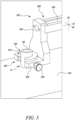
FIG. 3 is a rear perspective view of the apparatus ofFIG. 2 ; -
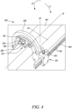
FIG. 4 illustrates a portion of the apparatus ofFIG. 2 wherein a reference hardware locator is in engagement with a pre-exiting hardware on the tubular structure; -
FIG. 5 illustrates a cylindrical hardware located on the tubular structure using the apparatus ofFIG. 2 ; -
FIG. 6 is a front perspective view of an apparatus for locating another hardware, such as, a plate, a block, a bracket, etc. at the desired location on the tubular structure of the machine ofFIG. 1 , according to another example of the present disclosure; and -
FIG. 7 illustrates the hardware located on the tubular structure using the apparatus ofFIG. 6 . - Wherever possible, the same reference numbers will be used throughout the drawings to refer to same or like parts. Referring to
FIG. 1 , a schematic side view of amachine 100 is illustrated. Themachine 100 is embodied as a mining truck that may be used to move payload, such as, asphalt, debris, dirt, snow, feed, gravel, logs, raw minerals, recycled material, rock, sand, woodchips, etc. from one location to another. However, themachine 100 may include any other work/construction machine, such as, a hydraulic excavator, a dozer, a wheel loader, a track-type tractor, a motor grader, or any other machine that may be used for purposes, such as, digging, construction, landscaping, and the like. Alternatively, themachine 100 may include a passenger vehicle, such as, a car, a van, a bus, etc. that may be used for transportation of passengers from one location to another. - The
machine 100 includes aframe 102. Theframe 102 is formed from a number of tubular structures that are joined with each other. One suchtubular structure 104 is illustrated inFIGS. 4 ,5 , and7 . Further, theframe 102 supports a pair offront wheels 106 and a pair ofrear wheels 108 of themachine 100. Themachine 100 further includes adump body 110 that may hold the payload therein. Themachine 100 also includes anenclosure 112 and anoperator cabin 114 mounted to theframe 102. Theenclosure 112 may house a power source (not shown). The power source may include, for example, a battery pack to provide power to various components of themachine 100 for operational and mobility requirements. The battery pack may include one or more battery modules, each of which may include battery cells, such as, lithium titanate battery cells. In other examples, the power source may include a fuel cell or an engine (for e.g., an internal combustion engine). - It should be noted that the
frame 102 may support a number of machine parts, such as, components of the battery pack and/or a control unit thereon, without any limitations. In order to mount the machine parts on thetubular structure 104 of theframe 102, one ormore hardware 116, 118 (shown inFIGS. 5 and7 , respectively) may have to be coupled to thetubular structure 104. Thehardware 116 has a circular profile herein. Specifically, thehardware 116 includes a boss. Alternatively, thehardware 116 may include any other element having a circular profile, such as, a cylindrical member. Further, thehardware 118 has a non-circular profile herein. Specifically, thehardware 118 includes a bracket. Alternatively, thehardware 118 may include a plate or a block or any other element that may assist in mounting machine parts on thetubular structure 104. It should be noted that the present disclosure is not limited by a shape of thehardware - The present disclosure relates to a system 200 (shown inf
FIG. 2 ) for locating thehardware FIGS. 5 and7 ) on thetubular structure 104 of themachine 100. Thesystem 200 includes a pre-existing hardware 120 (shown inFIG. 4 ) mounted on thetubular structure 104. Thepre-existing hardware 120 is used as a reference to locate thehardware tubular structure 104. Thepre-existing hardware 120 is embodied as a boss herein. However, it should be noted that thepre-existing hardware 120 may include any other element, without any limitations. - Referring to
FIG. 2 , thesystem 200 includes anapparatus 202 for locating the hardware 116 (seeFIG. 4 ) at the desired location L1 (seeFIG. 5 ) on the tubular structure 104 (seeFIG. 5 ) of themachine 100. In an example, various components of theapparatus 202 may be made from a metallic material. However, it may be contemplated that the components of theapparatus 202 may be made from high strength polymers. Theapparatus 202 includes alinear element 204 extending along a longitudinal axis A1, and defining afirst end 206 and asecond end 208. Thelinear element 204 includes a number oflinear reference indicia 210 thereon. Thelinear element 204 is embodied as a rectangular bar herein. - Further, the
apparatus 202 includes aslider 212 coupled to thelinear element 204. Thelinear element 204 is linearly slidable relative to theslider 212 along the longitudinal axis A1 to dispose theslider 212 at any one of the number oflinear reference indicia 210 based on the desired location L1 of thehardware 116. Theslider 212 includes arectangular block 214. Therectangular block 214 receives a portion of thelinear element 204 therethrough. Further, theslider 212 includes a pair ofcoupling elements 216 extending from therectangular block 214 along a vertical axis A2. In the illustrated example ofFIG. 2 , therectangular block 214 is integral with eachcoupling element 216. Alternatively, therectangular block 214 and thecoupling elements 216 may be manufactured as separate components, and may be joined with each other to form theslider 212. - The
slider 212 includes afirst fastening member 218 that couples theslider 212 with thelinear element 204. Thefirst fastening member 218 is embodied as a clamp herein. In order to dispose theslider 212 at any one of the number oflinear reference indicia 210, thefirst fastening member 218 may be loosened to facilitate movement of thelinear element 204 relative to theslider 212. Further, thefirst fastening member 218 may be tightened to prevent any unintentional movement of thelinear element 204 relative to theslider 212. - The
apparatus 202 further includes anangular element 220. Theangular element 220 is substantially semi-circular in shape. Theangular element 220 can be coupled with and at least partially surround the tubular structure 104 (as shown inFIG. 4 ). An inner diameter defined by theangular element 220 may be slightly greater than an outer diameter of thetubular structure 104 so that theangular element 220 may surround thetubular structure 104 when theapparatus 202 is coupled with thetubular structure 104. Theslider 212 is angularly slidable relative to theangular element 220. Theangular element 220 includes a number ofangular reference indicia 222 thereon. Further, theslider 212 is disposable at any one of the number ofangular reference indicia 222 based on the desired location L1 of thehardware 116. It should be noted that theslider 212 may be moved along a clockwise direction C1 or an anti-clockwise direction C2 relative to theangular element 220 to dispose theslider 212 at any one of the number ofangular reference indicia 222. - The
slider 212 includes asecond fastening member 224 that couples theslider 212 with theangular element 220. Thesecond fastening member 224 is embodied as a clamp herein. In order to dispose theslider 212 at any one of the number ofangular reference indicia 222, thesecond fastening member 224 may be loosened to facilitate movement of thelinear element 204 relative to theangular element 220. Further, thesecond fastening member 224 may be tightened to prevent any unintentional movement of theslider 212 relative to theangular element 220. Theslider 212 also includes apointer 226. Theslider 212 may be movable relative to theangular element 220, so that thepointer 226 may point at a particularangular reference indicia 222. - Further, the
angular element 220 includes one ormore magnets 228 and one or morethird fastening members 230. The one ormore magnets 228 and the one or morethird fastening members 230 couple theangular element 220 with thetubular structure 104. Themagnets 228 are circumferentially spaced apart from each other along theangular element 220. Only onemagnet 228 is illustrated herein, however, theangular element 220 includesmultiple magnets 228 that are obstructed from the view illustrated inFIG. 2 . In some examples, a total number of themagnets 228 may be based on a dimension of thetubular structure 104 and a dimension of theangular element 220. Further, theangular element 220 includes twothird fastening members 230 herein. Thethird fastening members 230 are embodied as clamps herein. Thethird fastening members 230 may be loosened to couple or remove theangular element 220 from thetubular structure 104. Further, thethird fastening members 230 may be tightened to prevent any unintentional movement of theangular element 220 relative to thetubular structure 104. - The
apparatus 202 includes ahardware locator 232 coupled to thelinear element 204 at thefirst end 206 thereof. It should be noted that thehardware locator 232 is removably coupled with thelinear element 204. Thehardware locator 232 engages with thehardware 116 to locate thehardware 116 at the desired location L1 on thetubular structure 104. Thehardware locator 232 includes an L-shaped design. Thehardware locator 232 includes afirst plate 234 coupled with thelinear element 204. Thefirst plate 234 is substantially orthogonal to thelinear element 204. Specifically, thefirst plate 234 extends along the vertical axis A2. Thehardware locator 232 also includes asecond plate 236. The first andsecond plates second plate 236 extends from thefirst plate 234 along the longitudinal axis A1. Thesecond plate 236 defines a slot (not shown) that is substantially U-shaped. - Further, when the
hardware 116 includes the circular profile, thehardware locator 232 includes abush 240 to locate thehardware 116 at the desired location L1 on thetubular structure 104. Thebush 240 engages with thehardware 116 for locating thehardware 116 on thetubular structure 104. It should be noted that thesecond plate 236 may be designed to hold bushes of different dimensions, based on a dimension of thehardware 116. Thebush 240 includes afirst portion 242 that rests on thesecond plate 236, and asecond portion 244 extending from thefirst portion 242 that is received within the slot of thesecond plate 236. Further, thebush 240 also includes aslot 246 extending through the first andsecond portions slot 246 is substantially U-shaped. Theslot 246 is in alignment with the slot of thesecond plate 236. Further, theslot 246 receives thehardware 116 therein. - The
hardware locator 232 further includes a pair offourth fastening members 248. Thefourth fastening members 248 are embodied as clamps herein. Thefourth fastening members 248 facilitate coupling of thebush 240 with thesecond plate 236 of thehardware locator 232. Thefourth fastening members 248 may be loosened to replace thebush 240 as per the dimension of thehardware 116. Further, thefourth fastening members 248 may be tightened to prevent any unintentional movement of thebush 240 relative to thesecond plate 236. - The
apparatus 202 also includes a supportingblock 250 slidably coupled to thelinear element 204 and disposed between theslider 212 and thehardware locator 232. When theangular element 220 is coupled to thetubular structure 104, the supportingblock 250 abuts with thetubular structure 104. The supportingblock 250 may be disposed anywhere between theslider 212 and thehardware locator 232. The supportingblock 250 includes afifth fastening member 252 that couples the supportingblock 250 with thelinear element 204. Thefifth fastening member 252 is embodied as a clamp herein. Thefifth fastening member 252 may be loosened to facilitate movement of the supportingblock 250 relative to thelinear element 204. Further, thefifth fastening member 252 may be tightened to prevent any unintentional movement of the supportingblock 250 relative to thelinear element 204. - As shown in
FIG. 3 , theapparatus 202 includes areference hardware locator 254 coupled to theangular element 220. Theangular element 220 is coupled to the tubular structure 104 (seeFIG. 4 ) such that thereference hardware locator 254 engages with thepre-existing hardware 120 mounted on thetubular structure 104. Thereference hardware locator 254 extends from theangular element 220 along the longitudinal axis A1. Thereference hardware locator 254 includes aplate 256 defining a circular through-hole (not shown). Further, theplate 256 is coupled with areference bush 258 of thereference hardware locator 254. It should be noted that theplate 256 may be designed to hold bushes of different dimensions, based on a dimension of thepre-existing hardware 120. It should be noted that thereference bush 258 may be replaced by another reference element having a design and a dimension that may accommodate a design and the dimension of thepre-existing hardware 120. For example, if thepre-existing hardware 120 includes a plate, a block, or a bracket, thereference bush 258 may be replaced by an element that can engage with the said plate, block, or bracket. - The
reference bush 258 includes athird portion 260 that rests on theplate 256 and afourth portion 262 extending from thethird portion 260 and received within the circular through-hole of theplate 256. Further, thereference bush 258 includes a through-opening 264 that is in alignment with the circular through-hole of theplate 256. Further, the through-opening 264 receives the hardware 116 (seeFIG. 4 ) therein. - The
reference hardware locator 254 includes a pair ofsixth fastening members 266. Thesixth fastening members 266 are embodied as clamps herein. Thesixth fastening members 266 facilitate coupling of thereference bush 258 with theplate 256 of thereference hardware locator 254. Thesixth fastening members 266 may be loosened to replace thereference bush 258 as per the dimension of thepre-existing hardware 120. Further, thesixth fastening members 266 may be tightened to prevent any unintentional movement of thereference bush 258 relative to theplate 256. Moreover, thereference hardware locator 254 includes abush locator 268 that allows location of thereference bush 258 on theplate 256. - Referring to
FIG. 4 , when thehardware 116 is to be located on thetubular structure 104, theangular element 220 is coupled with thetubular structure 104 such that the pre-existing hardware 120 (seeFIG. 3 ) is received within the through-opening 264 of thereference bush 258. It should be noted that thehardware 116 to be located on thetubular structure 104 may have a predetermined linear orientation and a predetermined angular orientation with respect to thepre-existing hardware 120. For example, thehardware 116 may have to be located at a predetermined linear distance and a predetermined angular distance from thepre-existing hardware 120. A user, such as an assembly personnel, may be aware of the values of the predetermined linear distance and the predetermined angular distance. In order to locate thehardware 116 at the predetermined angular orientation with respect to thepre-existing hardware 120, the user may move theslider 212 relative to the angular element 220 (in the clockwise direction C1 or the anti-clockwise direction C2) such that theslider 212 is disposed at a desiredangular reference indicia 222 that corresponds to the predetermined angular distance. Further, in order to locate thehardware 116 at the predetermined linear orientation with respect to thepre-existing hardware 120, the user may move thelinear element 204 relative to theslider 212 such that thelinear element 204 is disposed at a desiredlinear reference indicia 210 that corresponds to the predetermined linear distance. - Referring now to
FIG. 5 , once theapparatus 202 is adjusted to the desiredlinear reference indicia 210 and the desiredangular reference indicia 222, thehardware 116 may be engaged with thehardware locator 232. Subsequently, thehardware 116 may be tacked, welded, or bolted at the desired location L1, as per requirements. - Referring now to
FIGS. 6 and7 , a perspective view of anapparatus 602 for locating thehardware 118 at the desired location L1 on thetubular structure 104 of themachine 100 is illustrated. Theapparatus 602 is substantially similar to theapparatus 202 described in relation toFIGS. 2 to 5 , with common components being referred to by the same reference numerals. However, theapparatus 602 shown inFIG. 6 is used to locate thehardware 118 having a non-circular profile. Specifically, theapparatus 602 is used to locate thehardware 118 that is embodied as a bracket. Alternatively, thehardware 118 may include a plate, a block, or any other element having a non-circular profile. - As shown in
FIG. 6 , theapparatus 602 includes ahardware locator 632. Thehardware locator 632 is removably coupled with thelinear element 204. Thehardware locator 632 includes afirst plate 634 coupled with thelinear element 204 and is substantially orthogonal to thelinear element 204. Specifically, thefirst plate 634 extends along the vertical axis A2. Thehardware locator 632 also includes asecond plate 636. The first andsecond plates second plate 636 extends from thefirst plate 634 along the longitudinal axis A1. When thehardware 118 includes the non-circular profile, thehardware locator 632 includes a locatingbracket 670 to locate thehardware 118 at the desired location L1 (seeFIG. 7 ) on the tubular structure 104 (seeFIG. 7 ). The locatingbracket 670 is slidable relative to thelinear element 204 along a lateral axis A3 that is orthogonal to the longitudinal axis A1. Specifically, the locatingbracket 670 slides relative to thesecond plate 636. The locatingbracket 670 includes aslot 672, and a number oflinear reference indicia 674 thereon. Theslot 672 is substantially rectangular in shape and may accommodate at least a portion of thehardware 118 therein. - The
hardware locator 632 also includes acoupling assembly 678 that couples the locatingbracket 670 with thesecond plate 636. Thecoupling assembly 678 includes acoupling bracket 680 having apointer 682. The locatingbracket 670 may be movable relative to thesecond plate 636, so that thepointer 682 may point at a desiredlinear reference indicia 674 on the locatingbracket 670. Further, thecoupling assembly 678 includes aseventh fastening member 684. Theseventh fastening member 684 is embodied as a clamp herein. Theseventh fastening member 684 facilitates coupling of the locatingbracket 670 with thesecond plate 636. Theseventh fastening member 684 may be loosened to move the locatingbracket 670 relative to thesecond plate 636. Further, theseventh fastening members 684 may be tightened to prevent any unintentional movement of the locatingbracket 670 relative to thesecond plate 636. - When the
hardware 118 is to be located at the desired location L1, the user may move theslider 212 relative to the angular element 220 (in the clockwise direction C1 or the anti-clockwise direction C2) such that theslider 212 is disposed at a desiredangular reference indicia 222 that corresponds to a predetermined angular distance. Further, in order to locate thehardware 118 at a predetermined linear orientation with respect to thepre-existing hardware 120 along the longitudinal axis A1, the user may move thelinear element 204 relative to theslider 212 such that thelinear element 204 is disposed at a desiredlinear reference indicia 210 that corresponds to the predetermined linear distance. Moreover, in order to locate thehardware 118 at a predetermined linear orientation with respect to thepre-existing hardware 120 along the lateral axis A3, the user may move the locatingbracket 670 relative to thesecond plate 636 such that the locatingbracket 670 is disposed at a desiredlinear reference indicia 674. - Referring now to
FIG. 7 , once theapparatus 602 is adjusted to the desiredlinear reference indicia 210, 674 (along the longitudinal axis A1 and the lateral axis A3, respectively) and the desiredangular reference indicia 222, thehardware 118 may be engaged with thehardware locator 632. Subsequently, thehardware 118 may be tacked, welded, or bolted at the desired location L1, as per requirements. - It is to be understood that individual features shown or described for one embodiment may be combined with individual features shown or described for another embodiment. The above described implementation does not in any way limit the scope of the present disclosure. Therefore, it is to be understood although some features are shown or described to illustrate the use of the present disclosure in the context of functional segments, such features may be omitted from the scope of the present disclosure without departing from the spirit of the present disclosure as defined in the appended claims.
- The present disclosure relates to the
apparatus hardware apparatus hardware tubular structure 104. - The
apparatus hardware 116, and hardware having non-circular profiles, such as thehardware 118. More particularly, for locating thehardware 116, thehardware locator 232 may be coupled with thelinear element 204. Further, for locating thehardware 118, thehardware locator 632 may be coupled with thelinear element 204. Moreover, thelinear element 204 may be interchangeably coupled with thehardware locator 232 or thehardware locator 632. Thus, theapparatus hardware - The
hardware locators apparatus corresponding hardware hardware apparatus hardware apparatus hardware hardware apparatus apparatus hardware apparatus - While aspects of the present disclosure have been particularly shown and described with reference to the embodiments above, it will be understood by those skilled in the art that various additional embodiments may be contemplated by the modification of the disclosed machine, systems and methods without departing from the spirit and scope of the disclosure. Such embodiments should be understood to fall within the scope of the present disclosure as determined based upon the claims and any equivalents thereof.
Claims (10)
- An apparatus (202, 602) for locating a hardware (116, 118) at a desired location (L1) on a tubular structure (104) of a machine (100), the apparatus (202, 602) comprising:a linear element (204) extending along a longitudinal axis (A1), and defining a first end (206) and a second end (208), wherein the linear element (204) includes a plurality of linear reference indicia (210) thereon;a slider (212) coupled to the linear element (204), wherein the linear element (204) is linearly slidable relative to the slider (212) along the longitudinal axis (A1) to dispose the slider (212) at any one of the plurality of linear reference indicia (210) based on the desired location (L1) of the hardware (116, 118);an angular element (220) adapted to be coupled with and at least partially surround the tubular structure (104), wherein the slider (212) is angularly slidable relative to the angular element (220), wherein the angular element (220) includes a plurality of angular reference indicia (222) thereon, and wherein the slider (212) is disposable at any one of the plurality of angular reference indicia (222) based on the desired location (L1) of the hardware (116, 118);a hardware locator (232, 632) coupled to the linear element (204) at the first end (206) thereof, wherein the hardware locator (232, 632) is adapted to engage with the hardware (116, 118) to locate the hardware (116, 118) at the desired location (L1) on the tubular structure (104); anda reference hardware locator (254) coupled to the angular element (220), wherein the angular element (220) is coupled to the tubular structure (104) such that the reference hardware locator (254) engages with a pre-existing hardware (120) mounted on the tubular structure (104), and wherein the pre-existing hardware (120) is used as a reference to locate the hardware (116, 118) at the desired location (L1) on the tubular structure (104).
- The apparatus (202, 602) of claim 1, wherein the apparatus (202, 602) includes a supporting block (250) slidably coupled to the linear element (204) and disposed between the slider (212) and the hardware locator (232, 632), and wherein, when the angular element (220) is coupled to the tubular structure (104), the supporting block (250) abuts with the tubular structure (104).
- The apparatus (202, 602) of claim 1, wherein the slider (212) includes a first fastening member (218) that couples the slider (212) with the linear element (204) and a second fastening member (224) that couples the slider (212) with the angular element (220).
- The apparatus (202, 602) of claim 1, wherein the angular element (220) includes at least one magnet (228) and at least one third fastening member (230), and wherein the at least one magnet (228) and the at least one third fastening member (230) couple the angular element (220) with the tubular structure (104).
- The apparatus (202) of claim 1, wherein, when the hardware (116) includes a circular profile, the hardware locator (232) includes a bush (240) to locate the hardware (116) at the desired location (L1) on the tubular structure (104).
- The apparatus (602) of claim 1, wherein, when the hardware (118) includes a non-circular profile, the hardware locator (632) includes a locating bracket (670) to locate the hardware (118) at the desired location (L1) on the tubular structure (104), wherein the locating bracket (670) is slidable relative to the linear element (204) along a lateral axis (A3) that is orthogonal to the longitudinal axis (A1), and wherein the locating bracket (670) includes a slot (672), and a plurality of linear reference indicia (674) thereon.
- A system (200) for locating a hardware (116, 118) at a desired location (L1) on a tubular structure (104) of a machine (100), the system (200) comprising:a pre-existing hardware (120) mounted on the tubular structure (104), wherein the pre-existing hardware (120) is used as a reference to locate the hardware (116, 118) at the desired location (L1) on the tubular structure (104); andan apparatus (202, 602) adapted to locate the hardware (116, 118) at the desired location (L1) on the tubular structure (104) using the pre-existing hardware (120) as the reference, the apparatus (202, 602) including:a linear element (204) extending along a longitudinal axis (A1), and defining a first end (206) and a second end (208), wherein the linear element (204) includes a plurality of linear reference indicia (210) thereon;a slider (212) coupled to the linear element (204), wherein the linear element (204) is linearly slidable relative to the slider (212) along the longitudinal axis (A1) to dispose the slider (212) at any one of the plurality of linear reference indicia (210) based on the desired location (L 1) of the hardware (116, 118);an angular element (220) adapted to be coupled with and at least partially surround the tubular structure (104), wherein the slider (212) is angularly slidable relative to the angular element (220), wherein the angular element (220) includes a plurality of angular reference indicia (222) thereon, and wherein the slider (212) is disposable at any one of the plurality of angular reference indicia (222) based on the desired location (L1) of the hardware (116, 118);a hardware locator (232, 632) coupled to the linear element (204) at the first end (206) thereof, wherein the hardware locator (232, 632) is adapted to engage with the hardware (116, 118) to locate the hardware (116, 118) at the desired location (L1) on the tubular structure (104); anda reference hardware locator (254) coupled to the angular element (220), wherein the angular element (220) is coupled to the tubular structure (104) such that the reference hardware locator (254) engages with the pre-existing hardware (120) mounted on the tubular structure (104).
- The system (200) of claim 7, wherein the apparatus (202, 602) includes a supporting block (250) slidably coupled to the linear element (204) and disposed between the slider (212) and the hardware locator (232, 632), and wherein, when the angular element (220) is coupled to the tubular structure (104), the supporting block (250) abuts with the tubular structure (104).
- The system (200) of claim 7, wherein, when the hardware (116) includes a circular profile, the hardware locator (232) includes a bush (240) to locate the hardware (116) at the desired location (L1) on the tubular structure (104).
- The system (200) of claim 7, wherein, when the hardware (118) includes a non-circular profile, the hardware locator (632) includes a locating bracket (670) to locate the hardware (118) at the desired location (L1) on the tubular structure (104), wherein the locating bracket (670) is slidable relative to the linear element (204) along a lateral axis (A3) that is orthogonal to the longitudinal axis (A1), and wherein the locating bracket (670) includes a slot (672), and a plurality of linear reference indicia (674) thereon.
Applications Claiming Priority (1)
| Application Number | Priority Date | Filing Date | Title |
|---|---|---|---|
| IN202311032695 | 2023-05-09 |
Publications (2)
| Publication Number | Publication Date |
|---|---|
| EP4474761A1 true EP4474761A1 (en) | 2024-12-11 |
| EP4474761B1 EP4474761B1 (en) | 2026-06-03 |
Family
ID=90721432
Family Applications (1)
| Application Number | Title | Priority Date | Filing Date |
|---|---|---|---|
| EP24169569.1A Active EP4474761B1 (en) | 2023-05-09 | 2024-04-11 | Apparatus for locating hardware on a tubular element |
Country Status (2)
| Country | Link |
|---|---|
| US (1) | US20240375232A1 (en) |
| EP (1) | EP4474761B1 (en) |
Citations (5)
| Publication number | Priority date | Publication date | Assignee | Title |
|---|---|---|---|---|
| US2178293A (en) * | 1937-12-03 | 1939-10-31 | Messerschmitt Boelkow Blohm | Measuring device |
| US3130496A (en) | 1960-12-14 | 1964-04-28 | Copeland Roy Dee | Angle measuring and cutting device for tubular conduits |
| US7178252B1 (en) * | 2003-11-05 | 2007-02-20 | Advanced Designs, L.L.C. | Pipe fitting aligning device |
| US7240437B1 (en) * | 2006-03-20 | 2007-07-10 | Emilian Moldovan | Pipe sizing and alignment device |
| WO2014059297A1 (en) * | 2012-10-11 | 2014-04-17 | Hypertherm, Inc. | Apparatuses for cutting a section of pipe having a non linear longitudinal axis; method of cutting such a pipe |
-
2024
- 2024-04-11 EP EP24169569.1A patent/EP4474761B1/en active Active
- 2024-05-01 US US18/652,510 patent/US20240375232A1/en active Pending
Patent Citations (5)
| Publication number | Priority date | Publication date | Assignee | Title |
|---|---|---|---|---|
| US2178293A (en) * | 1937-12-03 | 1939-10-31 | Messerschmitt Boelkow Blohm | Measuring device |
| US3130496A (en) | 1960-12-14 | 1964-04-28 | Copeland Roy Dee | Angle measuring and cutting device for tubular conduits |
| US7178252B1 (en) * | 2003-11-05 | 2007-02-20 | Advanced Designs, L.L.C. | Pipe fitting aligning device |
| US7240437B1 (en) * | 2006-03-20 | 2007-07-10 | Emilian Moldovan | Pipe sizing and alignment device |
| WO2014059297A1 (en) * | 2012-10-11 | 2014-04-17 | Hypertherm, Inc. | Apparatuses for cutting a section of pipe having a non linear longitudinal axis; method of cutting such a pipe |
Also Published As
| Publication number | Publication date |
|---|---|
| US20240375232A1 (en) | 2024-11-14 |
| EP4474761B1 (en) | 2026-06-03 |
Similar Documents
| Publication | Publication Date | Title |
|---|---|---|
| EP3946995B1 (en) | A system and a method for installation of traction batteries for a vehicle | |
| US7824145B2 (en) | Common pivot and support member for attachment interface | |
| US20150056052A1 (en) | Construction machine | |
| CN115723846A (en) | Modular main frame for work vehicles | |
| US20240375232A1 (en) | Apparatus for Locating Hardware | |
| US20170145657A1 (en) | Wing for an implement | |
| EP3392414B1 (en) | Main frame, front loader equipped with main frame, and work vehicle equipped with main frame | |
| US20060186703A1 (en) | Rops canopy of hydraulic shovel | |
| US8328274B2 (en) | Cabin apparatus for moving vehicle | |
| EP0455868A2 (en) | Low-bed trailer suspension system | |
| EP4005873B1 (en) | Construction machine, antenna attachment method, and antenna attachment structure | |
| KR20150033817A (en) | Front loader and front loader with a Agricultural | |
| JPWO2018159860A1 (en) | Work vehicle cover, work vehicle cab and work vehicle | |
| US20170030051A1 (en) | Frame assembly of wheel loader | |
| CN102431005B (en) | Tool for assembling rear cover of car | |
| CN104334803A (en) | Utility Vehicle | |
| CN108572084A (en) | Fixation limiting device and method, the middle heavy truck vehicle of front-wheel six square phase slip ring | |
| US9855976B2 (en) | Actuation system for hood of a machine | |
| US20240409040A1 (en) | Display system for work machine | |
| CN211685344U (en) | Automobile fender positioning device | |
| JP2018044474A (en) | Exhaust pipe for construction machine, assembling method for exhaust pipe, and construction machine equipped with exhaust pipe | |
| US20250270794A1 (en) | Front loader | |
| US12071060B1 (en) | System and method for positioning or removing pin | |
| JP2018009416A (en) | Engine support method and engine support structure in construction machine | |
| US12523016B2 (en) | Work implement for construction machine |
Legal Events
| Date | Code | Title | Description |
|---|---|---|---|
| PUAI | Public reference made under article 153(3) epc to a published international application that has entered the european phase |
Free format text: ORIGINAL CODE: 0009012 |
|
| STAA | Information on the status of an ep patent application or granted ep patent |
Free format text: STATUS: THE APPLICATION HAS BEEN PUBLISHED |
|
| AK | Designated contracting states |
Kind code of ref document: A1 Designated state(s): AL AT BE BG CH CY CZ DE DK EE ES FI FR GB GR HR HU IE IS IT LI LT LU LV MC ME MK MT NL NO PL PT RO RS SE SI SK SM TR |
|
| STAA | Information on the status of an ep patent application or granted ep patent |
Free format text: STATUS: REQUEST FOR EXAMINATION WAS MADE |
|
| 17P | Request for examination filed |
Effective date: 20250527 |
|
| GRAP | Despatch of communication of intention to grant a patent |
Free format text: ORIGINAL CODE: EPIDOSNIGR1 |
|
| STAA | Information on the status of an ep patent application or granted ep patent |
Free format text: STATUS: GRANT OF PATENT IS INTENDED |
|
| RIC1 | Information provided on ipc code assigned before grant |
Ipc: G01B 5/02 20060101AFI20251006BHEP Ipc: G01B 3/04 20060101ALI20251006BHEP Ipc: B23K 7/00 20060101ALI20251006BHEP Ipc: B23K 37/053 20060101ALI20251006BHEP Ipc: G01B 3/56 20060101ALI20251006BHEP Ipc: G01B 5/00 20060101ALI20251006BHEP Ipc: G01B 5/25 20060101ALI20251006BHEP Ipc: G01B 11/27 20060101ALI20251006BHEP |
|
| INTG | Intention to grant announced |
Effective date: 20251110 |
|
| GRAS | Grant fee paid |
Free format text: ORIGINAL CODE: EPIDOSNIGR3 |
|
| P01 | Opt-out of the competence of the unified patent court (upc) registered |
Free format text: CASE NUMBER: UPC_APP_0004674_4474761/2026 Effective date: 20260209 |
|
| GRAA | (expected) grant |
Free format text: ORIGINAL CODE: 0009210 |
|
| STAA | Information on the status of an ep patent application or granted ep patent |
Free format text: STATUS: THE PATENT HAS BEEN GRANTED |
|
| AK | Designated contracting states |
Kind code of ref document: B1 Designated state(s): AL AT BE BG CH CY CZ DE DK EE ES FI FR GB GR HR HU IE IS IT LI LT LU LV MC ME MK MT NL NO PL PT RO RS SE SI SK SM TR |
|
| REG | Reference to a national code |
Ref country code: CH Ref legal event code: F10 Free format text: ST27 STATUS EVENT CODE: U-0-0-F10-F00 (AS PROVIDED BY THE NATIONAL OFFICE) Effective date: 20260603 Ref country code: GB Ref legal event code: FG4D |
|
| REG | Reference to a national code |
Ref country code: DE Ref legal event code: R096 Ref document number: 602024005186 Country of ref document: DE |
|
| REG | Reference to a national code |
Ref country code: IE Ref legal event code: FG4D |