EP4474731A2 - Heat source system and indoor unit of heat source system - Google Patents
Heat source system and indoor unit of heat source system Download PDFInfo
- Publication number
- EP4474731A2 EP4474731A2 EP24175352.4A EP24175352A EP4474731A2 EP 4474731 A2 EP4474731 A2 EP 4474731A2 EP 24175352 A EP24175352 A EP 24175352A EP 4474731 A2 EP4474731 A2 EP 4474731A2
- Authority
- EP
- European Patent Office
- Prior art keywords
- utilization
- pipe
- indoor unit
- source system
- outdoor unit
- Prior art date
- Legal status (The legal status is an assumption and is not a legal conclusion. Google has not performed a legal analysis and makes no representation as to the accuracy of the status listed.)
- Pending
Links
Images



Classifications
-
- F—MECHANICAL ENGINEERING; LIGHTING; HEATING; WEAPONS; BLASTING
- F25—REFRIGERATION OR COOLING; COMBINED HEATING AND REFRIGERATION SYSTEMS; HEAT PUMP SYSTEMS; MANUFACTURE OR STORAGE OF ICE; LIQUEFACTION SOLIDIFICATION OF GASES
- F25B—REFRIGERATION MACHINES, PLANTS OR SYSTEMS; COMBINED HEATING AND REFRIGERATION SYSTEMS; HEAT PUMP SYSTEMS
- F25B13/00—Compression machines, plants or systems, with reversible cycle
-
- F—MECHANICAL ENGINEERING; LIGHTING; HEATING; WEAPONS; BLASTING
- F24—HEATING; RANGES; VENTILATING
- F24D—DOMESTIC- OR SPACE-HEATING SYSTEMS, e.g. CENTRAL HEATING SYSTEMS; DOMESTIC HOT-WATER SUPPLY SYSTEMS; ELEMENTS OR COMPONENTS THEREFOR
- F24D11/00—Central heating systems using heat accumulated in storage masses
- F24D11/02—Central heating systems using heat accumulated in storage masses using heat pumps
- F24D11/0214—Central heating systems using heat accumulated in storage masses using heat pumps water heating system
-
- F—MECHANICAL ENGINEERING; LIGHTING; HEATING; WEAPONS; BLASTING
- F24—HEATING; RANGES; VENTILATING
- F24D—DOMESTIC- OR SPACE-HEATING SYSTEMS, e.g. CENTRAL HEATING SYSTEMS; DOMESTIC HOT-WATER SUPPLY SYSTEMS; ELEMENTS OR COMPONENTS THEREFOR
- F24D17/00—Domestic hot-water supply systems
- F24D17/02—Domestic hot-water supply systems using heat pumps
-
- F—MECHANICAL ENGINEERING; LIGHTING; HEATING; WEAPONS; BLASTING
- F24—HEATING; RANGES; VENTILATING
- F24D—DOMESTIC- OR SPACE-HEATING SYSTEMS, e.g. CENTRAL HEATING SYSTEMS; DOMESTIC HOT-WATER SUPPLY SYSTEMS; ELEMENTS OR COMPONENTS THEREFOR
- F24D19/00—Details
- F24D19/10—Arrangement or mounting of control or safety devices
- F24D19/1006—Arrangement or mounting of control or safety devices for water heating systems
- F24D19/1066—Arrangement or mounting of control or safety devices for water heating systems for the combination of central heating and domestic hot water
- F24D19/1072—Arrangement or mounting of control or safety devices for water heating systems for the combination of central heating and domestic hot water the system uses a heat pump
-
- F—MECHANICAL ENGINEERING; LIGHTING; HEATING; WEAPONS; BLASTING
- F24—HEATING; RANGES; VENTILATING
- F24H—FLUID HEATERS, e.g. WATER OR AIR HEATERS, HAVING HEAT-GENERATING MEANS, e.g. HEAT PUMPS, IN GENERAL
- F24H15/00—Control of fluid heaters
- F24H15/30—Control of fluid heaters characterised by control outputs; characterised by the components to be controlled
- F24H15/375—Control of heat pumps
- F24H15/38—Control of compressors of heat pumps
-
- F—MECHANICAL ENGINEERING; LIGHTING; HEATING; WEAPONS; BLASTING
- F25—REFRIGERATION OR COOLING; COMBINED HEATING AND REFRIGERATION SYSTEMS; HEAT PUMP SYSTEMS; MANUFACTURE OR STORAGE OF ICE; LIQUEFACTION SOLIDIFICATION OF GASES
- F25B—REFRIGERATION MACHINES, PLANTS OR SYSTEMS; COMBINED HEATING AND REFRIGERATION SYSTEMS; HEAT PUMP SYSTEMS
- F25B25/00—Machines, plants or systems, using a combination of modes of operation covered by two or more of the groups F25B1/00 - F25B23/00
- F25B25/005—Machines, plants or systems, using a combination of modes of operation covered by two or more of the groups F25B1/00 - F25B23/00 using primary and secondary systems
-
- F—MECHANICAL ENGINEERING; LIGHTING; HEATING; WEAPONS; BLASTING
- F25—REFRIGERATION OR COOLING; COMBINED HEATING AND REFRIGERATION SYSTEMS; HEAT PUMP SYSTEMS; MANUFACTURE OR STORAGE OF ICE; LIQUEFACTION SOLIDIFICATION OF GASES
- F25B—REFRIGERATION MACHINES, PLANTS OR SYSTEMS; COMBINED HEATING AND REFRIGERATION SYSTEMS; HEAT PUMP SYSTEMS
- F25B49/00—Arrangement or mounting of control or safety devices
- F25B49/02—Arrangement or mounting of control or safety devices for compression type machines, plants or systems
-
- F—MECHANICAL ENGINEERING; LIGHTING; HEATING; WEAPONS; BLASTING
- F24—HEATING; RANGES; VENTILATING
- F24D—DOMESTIC- OR SPACE-HEATING SYSTEMS, e.g. CENTRAL HEATING SYSTEMS; DOMESTIC HOT-WATER SUPPLY SYSTEMS; ELEMENTS OR COMPONENTS THEREFOR
- F24D2200/00—Heat sources or energy sources
- F24D2200/12—Heat pump
- F24D2200/123—Compression type heat pumps
-
- F—MECHANICAL ENGINEERING; LIGHTING; HEATING; WEAPONS; BLASTING
- F25—REFRIGERATION OR COOLING; COMBINED HEATING AND REFRIGERATION SYSTEMS; HEAT PUMP SYSTEMS; MANUFACTURE OR STORAGE OF ICE; LIQUEFACTION SOLIDIFICATION OF GASES
- F25B—REFRIGERATION MACHINES, PLANTS OR SYSTEMS; COMBINED HEATING AND REFRIGERATION SYSTEMS; HEAT PUMP SYSTEMS
- F25B2313/00—Compression machines, plants or systems with reversible cycle not otherwise provided for
- F25B2313/003—Indoor unit with water as a heat sink or heat source
-
- F—MECHANICAL ENGINEERING; LIGHTING; HEATING; WEAPONS; BLASTING
- F25—REFRIGERATION OR COOLING; COMBINED HEATING AND REFRIGERATION SYSTEMS; HEAT PUMP SYSTEMS; MANUFACTURE OR STORAGE OF ICE; LIQUEFACTION SOLIDIFICATION OF GASES
- F25B—REFRIGERATION MACHINES, PLANTS OR SYSTEMS; COMBINED HEATING AND REFRIGERATION SYSTEMS; HEAT PUMP SYSTEMS
- F25B2700/00—Sensing or detecting of parameters; Sensors therefor
- F25B2700/21—Temperatures
- F25B2700/2116—Temperatures of a condenser
- F25B2700/21161—Temperatures of a condenser of the fluid heated by the condenser
-
- F—MECHANICAL ENGINEERING; LIGHTING; HEATING; WEAPONS; BLASTING
- F25—REFRIGERATION OR COOLING; COMBINED HEATING AND REFRIGERATION SYSTEMS; HEAT PUMP SYSTEMS; MANUFACTURE OR STORAGE OF ICE; LIQUEFACTION SOLIDIFICATION OF GASES
- F25B—REFRIGERATION MACHINES, PLANTS OR SYSTEMS; COMBINED HEATING AND REFRIGERATION SYSTEMS; HEAT PUMP SYSTEMS
- F25B2700/00—Sensing or detecting of parameters; Sensors therefor
- F25B2700/21—Temperatures
- F25B2700/2117—Temperatures of an evaporator
- F25B2700/21171—Temperatures of an evaporator of the fluid cooled by the evaporator
Definitions
- the present invention relates to a heat source system using a heat pump and an indoor unit of such a heat source system.
- a heat source system that includes an outdoor unit to be installed outdoors and an indoor unit, which is also called a hydro unit, to be installed indoors.
- the outdoor unit is provided with a compressor, a four-way valve, and an outdoor heat exchanger
- the indoor unit is provided with a pump, an expansion tank, and an indoor heat exchanger.
- the compressor, the four-way valve, the outdoor heat exchanger, and the indoor heat exchanger constitute a refrigeration cycle apparatus in which a refrigerant circulates.
- the outdoor heat exchanger exchanges heat between the refrigerant and outside air
- the indoor heat exchanger exchanges heat between the refrigerant and fluid to be used such as water.
- the fluid to be used is referred to as utilization fluid.
- the indoor unit is connected to an outgoing pipe and a return pipe.
- the outgoing pipe supplies utilization fluid such as water to an indoor utilization device such as a hot water tank or a fan coil unit, and the return pipe introduces the utilization fluid after use in the utilization device into the indoor unit.
- the outgoing pipe is connected to an outflow port (i.e., outlet) of a heat medium of the indoor heat exchanger via an interior pipe of the indoor unit on the outgoing side
- the return pipe is connected to an inflow port (i.e., inlet) of the indoor heat exchanger via the interior pipe of the indoor unit on the return side.
- the expansion tank is provided in the interior pipe of the indoor unit on the outgoing side, and the pump is connected to the interior pipe of the indoor unit on the outgoing or return side.
- the indoor unit and the outdoor unit are connected to each other by two refrigerant pipes composed of one pipe on the outgoing side and the other pipe on the return side.
- the indoor heat exchanger is supplied with a high-temperature or low-temperature refrigerant from the outdoor unit, and exchanges heat between this refrigerant and the utilization fluid.
- both the outgoing pipe and the return pipe are connected to the indoor unit, and this configuration causes a problem that the number of man-hours required for pipe-connection work in the indoor unit increases and installation of the indoor unit is time-consuming. Since both the outgoing pipe and the return pipe need to be connected to the indoor unit, in some cases, the overall length of the piping becomes longer depending on positional relationship between the respective installation locations of the indoor unit and the utilization device, which requires higher performance of the pump and increases its manufacturing cost.
- an object of the present invention is to provide a heat source system that is simplified in configuration of its indoor unit to the extent of reducing both the size of the indoor unit and man-hours required for installing the indoor unit and is also decreased in piping length to the extent of contributing to the reduction of manufacturing cost.
- a heat source system includes: an indoor unit that includes an expansion tank and a pump configured to circulate utilization fluid; and an outdoor unit that includes a refrigeration cycle apparatus, the refrigeration cycle apparatus including a first heat exchanger that exchanges heat between a refrigerant and the utilization fluid, and being configured such that the refrigerant circulates through the first heat exchanger.
- the indoor unit is configured to be connectable to the outdoor unit via a relay pipe, and also be connectable to a utilization device via an outgoing pipe so that the utilization fluid having passed through the first heat exchanger is supplied to the utilization device via the relay pipe, the indoor unit, and the outgoing pipe.
- a return pipe for introducing the utilization fluid after use in the utilization device into the outdoor unit is configured to be directly connectable to the outdoor unit without passing through the indoor unit.
- the heat source system may further include a water temperature sensor configured to detect a temperature of the utilization fluid introduced into the outdoor unit via the return pipe.
- the heat source system may include a controller configured to control operation of the heat source system, and the controller preferably controls the operation of the heat source system based on the temperature of the utilization fluid detected by the water temperature sensor.
- the water temperature sensor may be disposed in the outdoor unit, and the controller may be disposed in the indoor unit.
- the outdoor unit may be configured to transmit the temperature of the utilization fluid detected by the water temperature sensor to the controller through communication, which may be wired or wireless.
- the controller may be configured to control operation of the heat source system based on the temperature of the utilization fluid transmitted from the outdoor unit.
- the outdoor unit may include an inflow port, an outflow port, and an inlet connection joint configured to connect the return pipe to the inflow port.
- the inflow port may be a port through which the utilization fluid before heat exchange by the first heat exchanger flows in.
- the outlet port may be a port through which the utilization fluid after heat exchange by the first heat exchanger flows out.
- the inlet connection joint may have a sensor fixing portion provided inside a housing of the outdoor unit.
- the sensor fixing portion may be a portion to which the water temperature sensor is fixed.
- the indoor unit may further include a housing provided with an inlet connection port and an outlet connection port.
- the inlet connection port may be a port to which the relay pipe is connected and through which the utilization fluid having passed through the first heat exchanger flows in from the relay pipe.
- the outlet connection port may be a port to which the outgoing pipe is connected and through which the utilization fluid flows out to the outgoing pipe.
- the indoor unit may further include an interior pipe housed in the housing.
- the interior pipe may be a pipe that connects the inlet connection port and the outlet connection port to allow the utilization fluid to flow therethrough.
- the indoor unit may include a backup heater housed in the housing.
- the pump may be housed in the housing and connected to the interior pipe to allow the utilization fluid to circulate.
- the expansion tank may be housed in the housing and connected to the interior pipe.
- the backup heater may be installed in such a manner that the backup heater is able to heat the utilization fluid flowing through the interior pipe.
- the backup heater may be connected to the interior pipe on an upstream side of the pump.
- the backup heater may be connected to the interior pipe on an upstream side of the expansion tank.
- An indoor unit may constitute a heat source system in cooperation with an outdoor unit that is configured to control a temperature of utilization fluid through refrigeration cycle.
- the indoor unit includes a housing provided with an inlet connection port and an outlet connection port, an interior pipe, a pump, and an expansion tank.
- the inlet connection port is a port through which the utilization fluid subjected to temperature control by the outdoor unit flows in.
- the outlet connection port is a port through which the utilization fluid flows out to a utilization device.
- the interior pipe is housed in the housing and connects the inlet connection port and the outlet connection port to allow the utilization fluid to flow therethrough.
- the pump is housed in the housing and connected to the interior pipe to allow the utilization fluid to circulate.
- the expansion tank is housed in the housing and connected to the interior pipe. In this aspect, the housing does not have a connection port to be connected with a flow path through which the utilization fluid after use in the utilization device flows.
- the indoor unit may further include a backup heater housed in the housing and installed in such a manner that the backup heater is able to heat the utilization fluid flowing through the interior pipe.
- the backup heater may be connected to the interior pipe on an upstream side of the pump.
- the backup heater may be connected to the interior pipe on an upstream side of the expansion tank.
- the configuration of an indoor unit can be simplified by installing a first heat exchanger in an outdoor unit and disposing a pump for circulating utilization fluid and an expansion tank in the indoor unit.
- a return pipe is configured to be directly connectable to the outdoor unit without going through the indoor unit, and this configuration can downsize the indoor unit and reduce man-hours required for pipe-connection work and installation of the indoor unit.
- This configuration can also shorten piping length on the return side from a utilization device to the outdoor unit, and can reduce its manufacturing cost by optimizing performance required of the pump.
- the indoor unit can be structurally simplified. Further, the indoor unit is configured to be disposed independently of the flow path through which the utilization fluid after use in the utilization device flows, and such a configuration can reduce the man-hours required for pipe-connection work and installation of the indoor unit and can also shorten the length of the overall piping involved in installation of the heat source unit so as to reduce the manufacturing cost.
- a heat source system S includes an indoor unit 1, an outdoor unit 2, and a manual operating device 3.
- the heat source system S cools or heats utilization fluid that is circulated between the heat source system S and at least one utilization device 4, which is configured as an indoor fan coil unit serving as a cooling/heating device, a floor heating system, or a hot water storage device, for example.
- the number of utilization devices 4 may be one or plural regardless of whether the utilization devices 4 are of the same type or different types.
- One aspect of a plurality of different utilization devices 4 is a combination of a fan coil unit and a hot water storage device, for example.
- the heat source system S is connected to the utilization device 4 via an outgoing pipe Pf and a return pipe Pr, supplies the utilization device 4 with the utilization fluid subjected to temperature control by the heat source system S via the outgoing pipe Pf connected to the indoor unit 1, and directly returns the utilization fluid after use in the utilization device 4 to the outdoor unit 2 via the return pipe Pr connected to the utilization device 4.
- water is generally used as the utilization fluid
- brine is used in some cases for the purpose of antifreeze, for example.
- water is used as the utilization fluid.
- Any medium that can form a refrigeration cycle can be used as the refrigerant, such as an R410A refrigerant, an R32 refrigerant, and a CO 2 refrigerant.
- the heat source system S is configured as a combination of the indoor unit 1 and the outdoor unit 2, both of which are provided independently.
- the indoor unit 1 has a vertically long housing in the shape of a rectangular parallelepiped, and is installed for example on a wall indoors (in a mechanical room, a basement, or the like isolated from a living space).
- the outdoor unit 2 has a box-shaped housing and is installed outdoors.
- the manual operating device 3 is a so-called remote controller and is installed indoors at a position where a user can operate it. Specifically, the manual operating device 3 is installed on a wall in the living space.
- the respective housings of the indoor unit 1 and the outdoor unit 2 are schematically indicated by the two-dot chain-line frames.
- the indoor unit 1 includes an indoor-unit controller 10, an expansion tank 12, and a pump 11 that circulates the utilization fluid between the outdoor unit 2 and the utilization device 4.
- the pump 11, the expansion tank 12, and the indoor-unit controller 101 are accommodated in the housing of the indoor unit 1.
- the indoor unit 1 includes an interior pipe 15 through which water serving as the utilization fluid can flow.
- the pump 11 and the expansion tank 12 are connected to the interior pipe 15.
- the indoor unit 1 further includes a backup heater 13 and an overpressure prevention valve 14.
- the inlet for the utilization fluid communicates with the inlet opening 15a via the upstream portion of the interior pipe 15, and the outlet for the utilization fluid communicates with a suction port of the pump 11 via the middle portion of the interior pipe 15.
- the pump 11 has a discharge port that communicates with the outlet opening 15b via the downstream portion of the interior pipe 15.
- the inlet opening 15a, the backup heater 13, the pump 11, and the outlet opening 15b are connected in series via the interior pipe 15 in terms of the flow of the utilization fluid.
- the expansion tank 12 is connected to the interior pipe 15 via a branch pipe 16 that branches from the middle portion of the interior pipe 15, i.e., from the portion of the interior pipe 15 between the backup heater 13 and the pump 11.
- the overpressure prevention valve 14 is provided on the branch pipe 16.
- the branch pipe 16 ends at the expansion tank 12, and there is no pipe-connection beyond the expansion tank 12.
- the pump 11 imparts potential energy corresponding to a lifting height to the utilization fluid that is circulated between the pump 11 and the utilization device 4.
- the indoor unit 1 is disposed on the outlet side of the outdoor unit 2, and the disposition of the pump 11 with respect to the outdoor unit 2 is on the tension side or suction side due to the positional relationship between the indoor unit 1 and the outdoor unit 2.
- the expansion tank 12 suppresses a pressure rise of the utilization fluid flowing through the piping, and thereby suppresses damage to the piping to be caused by excessive expansion ascribable to heating of the utilization fluid.
- the expansion tank 12 is preferably located on the upstream side of the pump 11 with respect to the flow of utilization fluid in the interior pipe 15 in view of its function, the expansion tank 12 may also be disposed on the downstream side. When the expansion tank 12 is disposed on the upstream side of the pump 11 in the interior pipe 15, this configuration can prevent the effect of excessive expansion of the utilization fluid from spreading to the pump 11, and thereby can protect the pump 11 and also ensure stable operation of the pump 11.
- the backup heater 13 is installed in the indoor unit 1.
- the backup heater 13 When heating of the utilization fluid by a heat exchanger 21 of the outdoor unit 2 for exchanging heat between the utilization fluid and the refrigerant is insufficient, for example, when the outside temperature is low, the backup heater 13 is activated to supplementally heat the utilization fluid.
- the heat exchanger 21 Since water is used as the utilization fluid in the present embodiment, the heat exchanger 21 is hereinafter referred to as the water heat exchanger 21.
- the backup heater 13 includes an air vent valve 13a.
- the air vent valve 13a releases gas generated from the utilization fluid due to heating in the backup heater 13 to the outside.
- the backup heater 13 is disposed on the upstream side of the pump 11 and on the upstream side of the expansion tank 12 in the interior pipe 15. Such a disposition can supply the utilization fluid adjusted in temperature with respect to a setting temperature to the utilization device 4 at an appropriate flow rate, while reliably alleviating the effect of excessive expansion due to heating in the backup heater 13.
- the overpressure prevention valve 14 opens to release the pressure outside the pipe and protect the interior pipe 15.
- the outdoor unit 2 includes a compressor 22, an air/refrigerant heat exchanger 23, a four-way valve 24, an expansion valve 25, and a refrigerant pipe 26 in addition to the water heat exchanger 21.
- the outdoor unit 2 further includes an outdoor-unit controller 201.
- the water heat exchanger 21, the compressor 22, the air/refrigerant heat exchanger 23, the four-way valve 24, and the expansion valve 25 constitute a heat-pump type refrigeration cycle apparatus in which the refrigerant circulates through the refrigerant pipe 26 while undergoing a phase change.
- These refrigeration cycle components i.e., the water heat exchanger 21, the compressor 22, the air/refrigerant heat exchanger 23, the four-way valve 24, the expansion valve 25, and the refrigerant pipe 26 are housed in the housing of the outdoor unit 2.
- the water heat exchanger 21 constitutes a "first heat exchanger" according to the present embodiment.
- the water heat exchanger 21 is configured as a plate type heat exchanger, for example.
- the water heat exchanger 21 includes a plurality of plates arranged inside in such a manner that the refrigerant and the utilization fluid alternately flow through the gaps formed between these plates.
- the plates provided as partition plates function as heat transfer members, and heat exchange is performed between the refrigerant and the utilization fluid by circulating the refrigerant and the utilization fluid along the front and back surfaces of the plates.
- the water heat exchanger 21 is not limited to the plate type heat exchanger but may also be a coil type heat exchanger or another type of heat exchanger.
- the coil-type heat exchanger is provided with a coil-shaped pipe through which the refrigerant flows and another coil-shaped pipe through which the utilization fluid flows (hereinafter both pipes are collectively referred to as the flow pipes), and has a structure in which both flow pipes are joined or welded to each other so as to enable heat exchange between both.
- the respective flow pipes function as heat transfer members.
- the water heat exchanger 21 includes as a structure that allows the utilization fluid to flow through: an inlet port 21a communicated with an inlet-side pipe; and an outlet port 21b communicated with an outlet-side pipe.
- the compressor 22 compresses the refrigerant, raises its pressure, and then discharges the refrigerant.
- the compressor 22 is, for example, a sealed rotary compressor, inside of which is high pressure.
- the operating frequency F of the compressor 22 can be changed by known inverter control, and discharge amount of the refrigerant can be adjusted by changing the operating frequency F. However, the operating frequency F does not need to be adjustable, and the compressor 22 may be operated at a constant speed by using the commercial frequency.
- the compressor 22 is provided with an accumulator 22a. When a liquid refrigerant is mixed in the refrigerant, the compressor 22 sucks in only the gaseous refrigerant after gas-liquid separation by the accumulator 22a.
- the air/refrigerant heat exchanger 23 (hereinafter referred to as "the air heat exchanger 23") exchanges heat between the refrigerant and the outside air.
- the air heat exchanger 23 is configured as, for example, a fin-and-tube heat exchanger.
- the air heat exchanger 23 includes a fan 23a and a motor that is its drive source, and promotes heat transfer between the refrigerant flowing through its tube and the outside air by forcibly forming a flow of the outside air along the surfaces of the fins with the use of the fan 23a.
- the air heat exchanger 23 constitutes a "second heat exchanger" according to the present embodiment.
- the four-way valve 24 switches the flow path of the refrigerant between during cold water generation and during hot water generation.
- the four-way valve 24 sets the flow path of the refrigerant discharged by the compressor 22 in the direction from the four-way valve 24 toward the air heat exchanger 23. Under this flow-setting, the refrigerant having left the four-way valve 24 passes through the air heat exchanger 23 and then flows into the water heat exchanger 21.
- the four-way valve 24 sets the flow path of the refrigerant discharged by the compressor 22 in the direction from the four-way valve 24 toward the water heat exchanger 21. Under this flow-setting, the refrigerant having left the four-way valve 24 passes through the water heat exchanger 21 and then flows into the air heat exchanger 23.
- the expansion valve 25 adjusts the pressure of the refrigerant having flowed out of a condenser (for example, the air heat exchanger 23 functioning as a condenser during the cold water generation) by the action of an orifice, and regulates the pressure of the refrigerant flowing toward an evaporator (for example, the water heat exchanger 21 functioning as an evaporator during the cold water generation) by using flow resistance to generate a pressure drop.
- a condenser for example, the air heat exchanger 23 functioning as a condenser during the cold water generation
- the refrigerant pipe 26 is formed of, for example, a copper pipe.
- the refrigerant pipe 26 connects the water heat exchanger 21, the compressor 22, the air heat exchanger 23, the four-way valve 24, and the expansion valve 25 in such a manner that the refrigerant can flow therebetween.
- the heat source system S and the utilization device 4 are connected via both the outgoing pipe Pf through which the utilization fluid subjected to temperature control by the heat source system S flows and the return pipe Pr through which the utilization fluid after use in the utilization device 4 flows.
- a relay pipe Pi is provided between the outdoor unit 2 and the indoor unit 1, and the outlet port 21b of the water heat exchanger 21 is connected to the inlet opening 15a of the interior pipe 15 of the indoor unit 1 via the relay pipe Pi.
- an inlet connection port 17i and an outlet connection port 17o are formed to penetrate the housing 17 from the inside to the outside.
- the pipe end of the relay pipe Pi is inserted into the housing 17 via the inlet connection port 17i, and the relay pipe Pi is connected to the inlet opening 15a of the interior pipe 15.
- the outlet opening 15b of the interior pipe 15 is connected to the outgoing pipe Pf, which communicates with the utilization device 4.
- the pipe end of the outgoing pipe Pf is inserted into the housing 17 via the outlet connection port 17o, and the outgoing pipe Pf is connected to the outlet opening 15b of the interior pipe 15.
- the return pipe Pr On the inlet side of the utilization fluid of the outdoor unit 2, i.e., on the discharge side of the utilization device 4, the return pipe Pr is directly connected to the outdoor unit 2 without passing through the indoor unit 1.
- the return pipe Pr bypasses the indoor unit 1 and connects the utilization device 4 to the outdoor unit 2, the indoor unit 1 does not have a connection portion or connection port of the return pipe Pr, and the indoor unit 1 has neither an interior pipe connected to the return pipe Pr nor an outflow port for discharging the utilization fluid toward the outdoor unit 2. That is, the indoor unit 1 is not on the path through which the utilization fluid after use in the utilization device 4 flows, and the indoor unit 1 is installed independently of the flow path on the return side of the utilization fluid.
- the indoor unit 1 does not have the connection portion of the return pipe Pr, the interior pipe connected to the return pipe Pr, or the outlet port toward the outdoor unit 2 in the above-described manner, the indoor unit 1 can be significantly downsized and the components to be accommodated in the housing 17 of the indoor unit 1 can be simplified.
- the connection structure between the return pipe Pr and the outdoor unit 2 it will be described below in more detail.
- the manual operating device 3 includes a manual operation unit 31, a display 32, and an audio output unit 33.
- the manual operation unit 31 includes various manual switches disposed at positions where the user can operate them, as exemplified by: a start switch configured to switch the heat source system S between operation and stop; a mode selector switch configured to switch the operation mode of the heat source system S; and a temperature adjustment switch configured to increase or decrease the setting temperature for heating/cooling air-conditioning and hot water supply.
- the heat source system S may be able to switch the operation mode between a cooling mode and a heating mode.
- the heat source system S may also be able to switch between the cooling mode, the heating mode, a hot water supply mode, and a combination mode of these three modes depending on the type of the utilization device 4 to be connected.
- the display 32 is installed at a position that is visible to the user, and displays the setting temperature and the operating state of the heat source system S, for example. Aspects of the state to be displayed by the display 32 include: the operation mode of the heat source system S such as the cooling mode and the heating mode; and information that the heat source system S is in operation, for example.
- the display 32 can be realized by using a liquid crystal panel.
- the audio output unit 33 outputs guidance to the user as auditory information, for example, in the form of voice.
- the control apparatus of the heat source system S is composed of the indoor-unit controller 101 provided in the indoor unit 1, the outdoor-unit controller 201 provided in outdoor unit 2, and the manual operating device 3.
- An inlet water-temperature sensor 211 provided on the inlet side of the water heat exchanger 21 inside the outdoor unit 2 is connected to the outdoor-unit controller 201.
- the inlet water-temperature sensor 211 detects the temperature of the utilization fluid before heat exchange by the water heat exchanger 21 (hereinafter referred to as "the inlet water-temperature Twi").
- An outlet water-temperature sensor 111 is connected to the indoor-unit controller 101.
- the outlet water-temperature sensor 111 is attached to the interior pipe 15 near the inlet opening 15a on the upstream side of the backup heater 13 of the indoor unit 1, and detects the temperature of the utilization fluid on the outlet side of the water heat exchanger 21, i.e., the temperature of the utilization fluid after heat exchange by the water heat exchanger 21 (hereinafter referred to as "the outlet water-temperature Two").
- the outlet water-temperature sensor 111 may be provided in the outlet-side piping portion of the water heat exchanger 21 inside the outdoor unit 2, and this disposition enables the outlet water-temperature sensor 111 to detect the outlet water-temperature Two at a position closer to the water heat exchanger 21.
- the portion near the installation position of the pump 11 is provided with a supply water temperature sensor 112 that detects the temperature of the utilization fluid to be supplied to the outgoing pipe Pf (hereinafter referred to as "the supply water temperature Tho").
- the supply water temperature Tho detected by the supply water temperature sensor 112 is read by the indoor-unit controller 101.
- the supply water temperature Tho approximately matches the outlet water-temperature Two.
- the supply water temperature Tho becomes higher than the outlet water-temperature Two (Tho>Two) due to heating of the utilization fluid by the backup heater 13.
- the indoor-unit controller 101, the outdoor-unit controller 201, and the manual operating device 3 are communicably connected to each other by signal lines C1 and C2.
- the indoor-unit controller 101 and the outdoor-unit controller 201 communicate bidirectionally via the signal line C1
- the indoor-unit controller 101 and the manual operating device 3 communicate bidirectionally via the signal line C2.
- the information acquired by the outdoor unit 2 is transmitted to the manual operating device 3 via the indoor-unit controller 101 as necessary.
- the information acquired by the manual operating device 3 is transmitted to the outdoor-unit controller 201 via the indoor-unit controller 101 as necessary. In this manner, information is shared between the indoor-unit controller 101, the outdoor-unit controller 201, and the manual operating device 3 to the extent necessary for the operation of the heat source system S.
- Each of the indoor-unit controller 101, the outdoor-unit controller 201, and the manual operating device 3 is composed of a microcomputer and its peripheral circuit and operates on the basis of control programs stored in a memory in advance.
- the information to be transmitted from the indoor-unit controller 101 to the outdoor-unit controller 201 includes an operation command for the outdoor unit 2, such as activation and stop of the outdoor unit 2 and the operating frequency F of the compressor 22.
- the information to be transmitted from the outdoor-unit controller 201 to the indoor-unit controller 101 includes the respective operating states of various devices installed in the outdoor unit 2, as exemplified by: activation and stop of the compressor 22; the operating frequency of the compressor 22; the inlet water-temperature Twi detected by the inlet water-temperature sensor 211; and notification that defrosting operation is in progress.
- the information to be transmitted from the indoor-unit controller 101 to the manual operating device 3 includes the supply water temperature Tho and information regarding display contents on the display 32 (e.g., the operating state of the outdoor unit 2), for example.
- the information to be transmitted from the manual operating device 3 to the indoor-unit controller 101 includes information based on the user's operation (e.g., a command to start or stop the heat source system S) and the setting temperature (water temperature) Ts, for example.
- the indoor-unit controller 101 functions as a main controller for controlling the operation of the heat source system S on the basis of the information acquired through various sensors and the information acquired from the outdoor-unit controller 201 and the manual operating device 3.
- the indoor-unit controller 101 constitutes a "controller" according to the present embodiment. Additionally, part of the control to be executed by the indoor-unit controller 101 in the present embodiment may be executed by another controller (for example, the outdoor-unit controller 201) such that the indoor-unit controller 101 and the other controller are made to function in combination. In this case, the indoor-unit controller 101 and the other controller work in cooperation with each other to constitute the "controller" according to the present embodiment.
- step S101 various control information items such as the inlet water-temperature Twi, the outlet water-temperature Two, and the setting temperature Ts are read in.
- Setting the capacity is performed by setting the operating frequency F (i.e., the inverter output frequency F) of the electric motor provided in the compressor 22.
- the operating frequency F is set by using proportional-integral control calculation or integral control calculation based on the difference ⁇ T, for example.
- step S103 it is determined whether to stop the compressor 22 or not. In other words, in the case of the inverter-driven compressor 22, it is determined whether its operating frequency F is 0 Hz or not. If the compressor 22 is to be stopped, the processing proceeds to the step S104. Otherwise, i.e., if the compressor 22 is to be operated, the processing proceeds to the step S105.
- step S104 a command signal to stop the compressor 22 is outputted, and the compressor 22 is stopped.
- the pump 11 is also stopped at the same timing as the stop timing of the compressor 22 or with a slight delay from the stop timing of the compressor 22.
- a command signal to operate the compressor 22 is outputted. This causes the compressor 22 to start when the compressor 22 is activated from a stopped state, and causes the compressor 22 to continue operating when the compressor 22 is in operation. While the compressor 22 is operating, the pump 11 is basically operating at the same time to circulate water, which is the utilization fluid.
- step S106 it is determined whether a timer Tm is in operation or not.
- the compressor 22 is stopped, if it is determined based on the inlet water-temperature Twi that there is a risk of freezing of the water in the water heat exchanger 21, the relay pipe Pi, or the return pipe Pr, the timer Tm starts its operation and ends its operation after elapse of a setting time such as 5 minutes from the start of its operation. If the timer Tm is in operation, the processing proceeds to the step S107. If the timer Tm is not in operation, the processing proceeds to the step S108.
- step S107 the pump 11 is operated to prevent freezing of the water in the relay pipe Pi and the return pipe Pr. If the pump 11 is already in operation, the pump 11 continues to operate.
- step S108 it is determined whether the inlet water-temperature Twi detected by the inlet temperature sensor 211 is lower than a predetermined temperature Lt or not.
- This predetermined temperature Lt is set as a temperature indicating that there is a risk of freezing of the utilization fluid, and is, for example, 4°C. If the inlet water-temperature Twi is lower than the predetermined temperature Lt, the processing proceeds to the step S109. If the inlet water-temperature Twi is equal to or higher than the predetermined temperature Lt, the processing proceeds to the step S110.
- the timer Tm is started or restarted. After starting, the timer Tm operates for the setting time. The timer Tm stops at the timing when this setting time elapses from its start, and repeatedly operates each time a restart command is inputted to the the timer Tm.
- step S110 the pump 11 is stopped or kept stopped.
- the comparison between the inlet water-temperature Twi and the predetermined temperature Lt is performed to determine in the step S108 whether there is a risk of freezing of the utilization fluid or not, and if it is determined that the inlet water-temperature Twi is lower than the predetermined temperature Lt and there is a risk of freezing of the utilization fluid, the timer Tm is started in the step S109 and the pump 11 is accordingly operated in the step S107. Further, while the timer Tm is operating, the pump 11 continues to operate in the step S107.
- the pump 11 is stopped in the step S110 on the condition that the inlet water-temperature Twi is equal to or higher than the predetermined temperature Lt. Thereafter, every time the inlet water-temperature Twi falls below the predetermined temperature Lt, the timer Tm is started in the step S109 and the pump 11 is operated in the step S107. As a result, after the compressor 22 is stopped, the intermittent operation of the pump 11 prevents the water flowing through the water heat exchanger 21 and the piping from freezing. When brine or antifreeze fluid is used as the utilization fluid, the above-described antifreeze control is unnecessary.
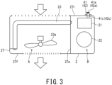
- Fig. 3 schematically illustrates the internal configuration of the outdoor unit 2 in a horizontal cross-section.
- the lower part of the sheet of Fig. 3 shows the front of the outdoor unit 2, and the upper part of the sheet of Fig. 3 shows the rear of the outdoor unit 2.
- the outside air passes through the interior of the outdoor unit 2 from the rear to the front as shown by the arrow in Fig. 3 .
- the outdoor unit 2 includes the housing 27 that accommodates various outdoor-unit components such as the water heat exchanger 21, and the interior of the housing 27 is divided into a blower chamber A and a machine chamber B on the respective left and right sides by a partition plate 27a that extends in the vertical direction.
- the blower chamber A houses the air heat exchanger 23 and the fan 23a, and openings for ventilation are provided in a front surface 27f and a rear surface 27r of the housing 27 facing the air heat exchanger 23.
- the machine chamber B houses refrigeration-cycle components excluding the air heat exchanger 23 and the fan 23a, specifically, houses the water heat exchanger 21, the compressor 22, and the four-way valve 24, for example.
- the partition plate 27a is made of, for example, sheet metal.
- the partition plate 27a is attached to the housing 27 in such a manner that extraneous substance such as rainwater having entered the blower chamber A through gaps such as the openings does not enter the machine chamber B. Furthermore, the outer contour including the top plate of the housing 27 and the partition plate 27a prevents direct intrusion of extraneous substance such as rainwater into the machine chamber B from the outside.
- the water heat exchanger 21 and the compressor 22 are disposed close to each other inside the machine chamber B.
- an inlet connection joint 41 and an outlet connection joint 42 are connected to the open end of the water pipe.
- the inlet connection joint 41 and the outlet connection joint 42 penetrate the rear surface 27r of the housing 27.
- the edge 41a of the inlet connection joint 41 and the edge 42a of outlet connection joint 42 extend to reach the outside of the housing 27.
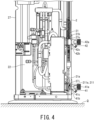
- Fig. 4 shows the internal structure of the machine chamber B of the outdoor unit 2 in a vertical cross-section.
- a lower open end and an upper open end are formed as open ends of the water pipe through which the utilization fluid flows.
- the lower open end is close to the installation surface D of the outdoor unit 2, and constitutes the inlet port 21a of the utilization fluid.
- the upper open end is far from the installation surface D, and constitutes the outlet port 21b of the utilization fluid.
- the utilization fluid is introduced into the water heat exchanger 21 via the inlet port 21a and is discharged from the water heat exchanger 21 via the outlet port 21b.
- the inlet port 21a and the outlet port 21b of the water heat exchanger 21 are both located inside the housing 27.
- the housing 27 has an inflow port 27i and an outflow port 27o, the utilization fluid before heat exchange by the water heat exchanger 21 flows into the outdoor unit 2 via the inflow port 27i, and the utilization fluid after heat exchange by the water heat exchanger 21 flows out of the outdoor unit 2 via the outflow port 27o.
- the return pipe Pr is connected to the inlet port 21a of the water heat exchanger 21 via the inlet connection joint 41 attached to its pipe end.
- the relay pipe Pi is connected to the outlet port 21b of the water heat exchanger 21 via the outlet connection joint 42 attached to its pipe end.
- the inlet connection joint 41 and the outlet connection joint 42 have the same structure except the part where the inlet connection joint 41 has a sensor fixing portion 211a.
- the inlet connection joint 41 and the outlet connection joint 42 penetrate the housing 27 of the outdoor unit 2 from the inside to the outside, and their edges 41a and 42a are located on the outside of the outdoor unit 2.
- the inlet connection joint 41 and the outlet connection joint 42 respectively have flanges 41b and 42b that extend vertically within a plane perpendicular to the central axis of the pipe conduit.
- the inflow port 27i and the outflow port 27o are closed by abutting and fixing the flanges 41b and 42b to the outer surface of the housing 27 of the outdoor unit 2, and thereby positioning of the inlet connection joint 41 and the outlet connection joint 42 with respect to the housing 27 is achieved.
- the respective base ends 41c and 42c of the inlet connection joint 41 and the outlet connection joint 42 are located inside the housing 27 of the outdoor unit 2, i.e., in the gap between the water heat exchanger 21 and the housing 27 of the outdoor unit 2.
- Fig. 5 is a perspective view of the joint structure on the inlet side of the water heat exchanger 21 as viewed diagonally from above, and illustrates an enlarged view of the inlet connection joint 41 and its surrounding region.
- Fig. 5 shows the state in which the housing 27 of the outdoor unit 2 is detached.
- the sensor fixing portion 211a for attaching the inlet water-temperature sensor 211 is formed at the base end 41c of the inlet connection joint 41, and the inlet water-temperature sensor 211 is attached to this sensor fixing portion 211a.
- the inlet water-temperature sensor 211 can be configured as a thermistor.
- the sensor fixing portion 211a may be a sensor holder on which the inlet water-temperature sensor 211 is detachably attached.
- the sensor fixing portion 211a may be configured such that the inlet water-temperature sensor 211 is non-removably embedded in the sensor fixing portion 211a.
- the respective base ends 41c and 42c of the inlet connection joint 41 and the outlet connection joint 42 are tightened with fasteners 51 to the inlet port 21a and the outlet port 21b of the water heat exchanger 21, and both are fixed to be watertight.
- the heat source system S includes the indoor unit 1 and the outdoor unit 2, and is configured to: supply the utilization fluid having passed through the outdoor unit 2 from the indoor unit 1 to the utilization device 4 via the outgoing pipe Pf; and return the utilization fluid after use in the utilization device 4 to the outdoor unit 2 via the return pipe Pr.
- the indoor unit 1 is provided with the pump 11 and the expansion tank 12, the outdoor unit 2 is provided with the refrigeration cycle apparatus that includes the water heat exchanger 21, the outdoor unit 2 and the indoor unit 1 are connected to each other via the relay pipe Pi, the indoor unit 1 and the utilization device 4 are connected to each other via the outgoing pipe Pf, and thus, the indoor unit 1 can be structurally simplified and downsized.
- the return pipe Pr installed from the utilization device 4 and configured as a flow path for the utilization fluid after use is directly connected to the outdoor unit 2 without passing through the indoor unit 1.
- the outgoing flow path i.e., the outgoing pipe Pf
- the return flow path i.e., the return pipe Pr
- This configuration allows the indoor unit 1 to omit: the connection portion (or connection port) of the return pipe Pr from the utilization device 4; the connection portion (or connection port) of the pipe connected to the return pipe Pr inside the indoor unit 1; or the connection portion (or connection port) of the return-side relay pipe extending from the outdoor unit 2. Omission of these components enables both miniaturization of the indoor unit 1 and reduction in man-hours required for pipe-connection work of the indoor unit 1 and installation of the return pipe Pr.
- the piping length of the return pipe Pr can be significantly shortened, and the total piping length of the overall piping including the outgoing pipe Pf and the return pipe Pr can be shortened.
- Such reduction in piping length can reduce the pressure drop in the piping, lower the lifting height required for the pump 11, and optimize the performance required of the pump 11 to reduce the manufacturing cost.
- the indoor unit 1 cannot directly detect the temperature of the utilization fluid after use in the utilization device 4, i.e., the inlet water-temperature Twi of the water heat exchanger 21, which needs to be detected in various control processes of the heat source system S.
- the inlet water-temperature Twi of the water heat exchanger 21 is detected by the outdoor-unit controller 201 as the temperature of the utilization fluid introduced into the outdoor unit 2 via the return pipe Pr, and thus, the operation of the heat source system S can be properly controlled without any problem by sharing this temperature information with the indoor-unit controller 101. Since the inlet water-temperature sensor 211 configured to detect the inlet water-temperature Twi is installed in the outdoor unit 2, the number of components to be installed in the indoor unit 1 can be reduced and the configuration of the indoor unit 1 can be further simplified.
- the sensor fixing portion 211a for fixing the inlet water-temperature sensor 211 is integrally formed on the inlet connection joint 41. This configuration enables installation of the inlet water-temperature sensor 211 even in a narrow space inside the outdoor unit 2, provides higher degree of freedom in the installation of the inlet water-temperature sensor 211, and allows a larger water heat exchanger 21 to be used and housed in the outdoor unit 2.
Landscapes
- Engineering & Computer Science (AREA)
- Physics & Mathematics (AREA)
- Thermal Sciences (AREA)
- Mechanical Engineering (AREA)
- General Engineering & Computer Science (AREA)
- Chemical & Material Sciences (AREA)
- Combustion & Propulsion (AREA)
- Other Air-Conditioning Systems (AREA)
Abstract
Description
- The present invention relates to a heat source system using a heat pump and an indoor unit of such a heat source system.
- As a system for generating cold or hot water for use in an indoor device, a heat source system that includes an outdoor unit to be installed outdoors and an indoor unit, which is also called a hydro unit, to be installed indoors. In such a known heat source system, the outdoor unit is provided with a compressor, a four-way valve, and an outdoor heat exchanger, while the indoor unit is provided with a pump, an expansion tank, and an indoor heat exchanger. The compressor, the four-way valve, the outdoor heat exchanger, and the indoor heat exchanger constitute a refrigeration cycle apparatus in which a refrigerant circulates. The outdoor heat exchanger exchanges heat between the refrigerant and outside air, and the indoor heat exchanger exchanges heat between the refrigerant and fluid to be used such as water. Hereinafter, the fluid to be used is referred to as utilization fluid.
- In such a heat source system, the indoor unit is connected to an outgoing pipe and a return pipe. The outgoing pipe supplies utilization fluid such as water to an indoor utilization device such as a hot water tank or a fan coil unit, and the return pipe introduces the utilization fluid after use in the utilization device into the indoor unit. Inside the indoor unit, the outgoing pipe is connected to an outflow port (i.e., outlet) of a heat medium of the indoor heat exchanger via an interior pipe of the indoor unit on the outgoing side, and the return pipe is connected to an inflow port (i.e., inlet) of the indoor heat exchanger via the interior pipe of the indoor unit on the return side. The expansion tank is provided in the interior pipe of the indoor unit on the outgoing side, and the pump is connected to the interior pipe of the indoor unit on the outgoing or return side. The indoor unit and the outdoor unit are connected to each other by two refrigerant pipes composed of one pipe on the outgoing side and the other pipe on the return side. The indoor heat exchanger is supplied with a high-temperature or low-temperature refrigerant from the outdoor unit, and exchanges heat between this refrigerant and the utilization fluid.
[Patent Document 1]JP 2017-180911 A - However, in the known heat source system, both the outgoing pipe and the return pipe are connected to the indoor unit, and this configuration causes a problem that the number of man-hours required for pipe-connection work in the indoor unit increases and installation of the indoor unit is time-consuming. Since both the outgoing pipe and the return pipe need to be connected to the indoor unit, in some cases, the overall length of the piping becomes longer depending on positional relationship between the respective installation locations of the indoor unit and the utilization device, which requires higher performance of the pump and increases its manufacturing cost.
- Since many other components such as the expansion tank and the pump in addition to the indoor heat exchanger are installed in the indoor unit, there is a further problem that disposition of the components inside the indoor unit becomes complicated and the housing for accommodating these components becomes larger in size.
- In view of the above-described circumstances, an object of the present invention is to provide a heat source system that is simplified in configuration of its indoor unit to the extent of reducing both the size of the indoor unit and man-hours required for installing the indoor unit and is also decreased in piping length to the extent of contributing to the reduction of manufacturing cost.
- To solve the above-mentioned problems, a heat source system according to one aspect of the present invention includes: an indoor unit that includes an expansion tank and a pump configured to circulate utilization fluid; and an outdoor unit that includes a refrigeration cycle apparatus, the refrigeration cycle apparatus including a first heat exchanger that exchanges heat between a refrigerant and the utilization fluid, and being configured such that the refrigerant circulates through the first heat exchanger. The indoor unit is configured to be connectable to the outdoor unit via a relay pipe, and also be connectable to a utilization device via an outgoing pipe so that the utilization fluid having passed through the first heat exchanger is supplied to the utilization device via the relay pipe, the indoor unit, and the outgoing pipe. A return pipe for introducing the utilization fluid after use in the utilization device into the outdoor unit is configured to be directly connectable to the outdoor unit without passing through the indoor unit.
- The heat source system may further include a water temperature sensor configured to detect a temperature of the utilization fluid introduced into the outdoor unit via the return pipe. In such case, the heat source system may include a controller configured to control operation of the heat source system, and the controller preferably controls the operation of the heat source system based on the temperature of the utilization fluid detected by the water temperature sensor.
- The water temperature sensor may be disposed in the outdoor unit, and the controller may be disposed in the indoor unit.
- The outdoor unit may be configured to transmit the temperature of the utilization fluid detected by the water temperature sensor to the controller through communication, which may be wired or wireless. In such case, the controller may be configured to control operation of the heat source system based on the temperature of the utilization fluid transmitted from the outdoor unit.
- The outdoor unit may include an inflow port, an outflow port, and an inlet connection joint configured to connect the return pipe to the inflow port. The inflow port may be a port through which the utilization fluid before heat exchange by the first heat exchanger flows in. The outlet port may be a port through which the utilization fluid after heat exchange by the first heat exchanger flows out.
- The inlet connection joint may have a sensor fixing portion provided inside a housing of the outdoor unit. The sensor fixing portion may be a portion to which the water temperature sensor is fixed.
- The indoor unit may further include a housing provided with an inlet connection port and an outlet connection port. The inlet connection port may be a port to which the relay pipe is connected and through which the utilization fluid having passed through the first heat exchanger flows in from the relay pipe. The outlet connection port may be a port to which the outgoing pipe is connected and through which the utilization fluid flows out to the outgoing pipe. In such case, the indoor unit may further include an interior pipe housed in the housing. The interior pipe may be a pipe that connects the inlet connection port and the outlet connection port to allow the utilization fluid to flow therethrough.
- The indoor unit may include a backup heater housed in the housing.
- The pump may be housed in the housing and connected to the interior pipe to allow the utilization fluid to circulate.
- The expansion tank may be housed in the housing and connected to the interior pipe.
- The backup heater may be installed in such a manner that the backup heater is able to heat the utilization fluid flowing through the interior pipe.
- The backup heater may be connected to the interior pipe on an upstream side of the pump.
- The backup heater may be connected to the interior pipe on an upstream side of the expansion tank.
- An indoor unit according to another aspect of the present invention may constitute a heat source system in cooperation with an outdoor unit that is configured to control a temperature of utilization fluid through refrigeration cycle. The indoor unit includes a housing provided with an inlet connection port and an outlet connection port, an interior pipe, a pump, and an expansion tank. The inlet connection port is a port through which the utilization fluid subjected to temperature control by the outdoor unit flows in. The outlet connection port is a port through which the utilization fluid flows out to a utilization device. The interior pipe is housed in the housing and connects the inlet connection port and the outlet connection port to allow the utilization fluid to flow therethrough. The pump is housed in the housing and connected to the interior pipe to allow the utilization fluid to circulate. The expansion tank is housed in the housing and connected to the interior pipe. In this aspect, the housing does not have a connection port to be connected with a flow path through which the utilization fluid after use in the utilization device flows.
- The indoor unit may further include a backup heater housed in the housing and installed in such a manner that the backup heater is able to heat the utilization fluid flowing through the interior pipe.
- The backup heater may be connected to the interior pipe on an upstream side of the pump.
- The backup heater may be connected to the interior pipe on an upstream side of the expansion tank.
- According to one aspect of the present invention, the configuration of an indoor unit can be simplified by installing a first heat exchanger in an outdoor unit and disposing a pump for circulating utilization fluid and an expansion tank in the indoor unit. Further, a return pipe is configured to be directly connectable to the outdoor unit without going through the indoor unit, and this configuration can downsize the indoor unit and reduce man-hours required for pipe-connection work and installation of the indoor unit. This configuration can also shorten piping length on the return side from a utilization device to the outdoor unit, and can reduce its manufacturing cost by optimizing performance required of the pump.
- According to another aspect, the indoor unit can be structurally simplified. Further, the indoor unit is configured to be disposed independently of the flow path through which the utilization fluid after use in the utilization device flows, and such a configuration can reduce the man-hours required for pipe-connection work and installation of the indoor unit and can also shorten the length of the overall piping involved in installation of the heat source unit so as to reduce the manufacturing cost.
- In the accompanying drawings:
-
Fig. 1 is a schematic diagram illustrating a configuration of a heat source system according to one embodiment of the present invention; -
Fig. 2 is a flowchart illustrating an overall flow of operation control of the heat source system; -
Fig. 3 is a schematic diagram illustrating an internal configuration of an outdoor unit; -
Fig. 4 is a schematic diagram illustrating a piping structure in the outdoor unit; and -
Fig. 5 is a perspective view illustrating a joint structure in a fluid introduction portion of a first heat exchanger. - Hereinbelow, embodiments of the present invention will be described by referring to the accompanying drawings.
- As shown in
Fig. 1 , a heat source system S according to one embodiment of the present invention includes anindoor unit 1, anoutdoor unit 2, and amanual operating device 3. The heat source system S cools or heats utilization fluid that is circulated between the heat source system S and at least oneutilization device 4, which is configured as an indoor fan coil unit serving as a cooling/heating device, a floor heating system, or a hot water storage device, for example. The number ofutilization devices 4 may be one or plural regardless of whether theutilization devices 4 are of the same type or different types. One aspect of a plurality ofdifferent utilization devices 4 is a combination of a fan coil unit and a hot water storage device, for example. The heat source system S is connected to theutilization device 4 via an outgoing pipe Pf and a return pipe Pr, supplies theutilization device 4 with the utilization fluid subjected to temperature control by the heat source system S via the outgoing pipe Pf connected to theindoor unit 1, and directly returns the utilization fluid after use in theutilization device 4 to theoutdoor unit 2 via the return pipe Pr connected to theutilization device 4. - Although water is generally used as the utilization fluid, brine is used in some cases for the purpose of antifreeze, for example. In the present embodiment, water is used as the utilization fluid. Any medium that can form a refrigeration cycle can be used as the refrigerant, such as an R410A refrigerant, an R32 refrigerant, and a CO2 refrigerant.
- The heat source system S is configured as a combination of the
indoor unit 1 and theoutdoor unit 2, both of which are provided independently. Theindoor unit 1 has a vertically long housing in the shape of a rectangular parallelepiped, and is installed for example on a wall indoors (in a mechanical room, a basement, or the like isolated from a living space). Theoutdoor unit 2 has a box-shaped housing and is installed outdoors. Themanual operating device 3 is a so-called remote controller and is installed indoors at a position where a user can operate it. Specifically, themanual operating device 3 is installed on a wall in the living space. InFig. 1 , the respective housings of theindoor unit 1 and theoutdoor unit 2 are schematically indicated by the two-dot chain-line frames. - The
indoor unit 1 includes an indoor-unit controller 10, anexpansion tank 12, and apump 11 that circulates the utilization fluid between theoutdoor unit 2 and theutilization device 4. Thepump 11, theexpansion tank 12, and the indoor-unit controller 101 are accommodated in the housing of theindoor unit 1. - Inside the
indoor unit 1, aninlet opening 15a is formed at one end and an outlet opening 15b is formed at the other end. Theindoor unit 1 includes aninterior pipe 15 through which water serving as the utilization fluid can flow. Thepump 11 and theexpansion tank 12 are connected to theinterior pipe 15. Theindoor unit 1 further includes abackup heater 13 and anoverpressure prevention valve 14. - In the
backup heater 13, the inlet for the utilization fluid communicates with theinlet opening 15a via the upstream portion of theinterior pipe 15, and the outlet for the utilization fluid communicates with a suction port of thepump 11 via the middle portion of theinterior pipe 15. - The
pump 11 has a discharge port that communicates with the outlet opening 15b via the downstream portion of theinterior pipe 15. - In other words, inside the
indoor unit 1, theinlet opening 15a, thebackup heater 13, thepump 11, and the outlet opening 15b are connected in series via theinterior pipe 15 in terms of the flow of the utilization fluid. - The
expansion tank 12 is connected to theinterior pipe 15 via abranch pipe 16 that branches from the middle portion of theinterior pipe 15, i.e., from the portion of theinterior pipe 15 between thebackup heater 13 and thepump 11. Theoverpressure prevention valve 14 is provided on thebranch pipe 16. In the present embodiment, thebranch pipe 16 ends at theexpansion tank 12, and there is no pipe-connection beyond theexpansion tank 12. - The
pump 11 imparts potential energy corresponding to a lifting height to the utilization fluid that is circulated between thepump 11 and theutilization device 4. In the present embodiment, theindoor unit 1 is disposed on the outlet side of theoutdoor unit 2, and the disposition of thepump 11 with respect to theoutdoor unit 2 is on the tension side or suction side due to the positional relationship between theindoor unit 1 and theoutdoor unit 2. - The
expansion tank 12 suppresses a pressure rise of the utilization fluid flowing through the piping, and thereby suppresses damage to the piping to be caused by excessive expansion ascribable to heating of the utilization fluid. Although theexpansion tank 12 is preferably located on the upstream side of thepump 11 with respect to the flow of utilization fluid in theinterior pipe 15 in view of its function, theexpansion tank 12 may also be disposed on the downstream side. When theexpansion tank 12 is disposed on the upstream side of thepump 11 in theinterior pipe 15, this configuration can prevent the effect of excessive expansion of the utilization fluid from spreading to thepump 11, and thereby can protect thepump 11 and also ensure stable operation of thepump 11. - The
backup heater 13 is installed in theindoor unit 1. When heating of the utilization fluid by aheat exchanger 21 of theoutdoor unit 2 for exchanging heat between the utilization fluid and the refrigerant is insufficient, for example, when the outside temperature is low, thebackup heater 13 is activated to supplementally heat the utilization fluid. Since water is used as the utilization fluid in the present embodiment, theheat exchanger 21 is hereinafter referred to as thewater heat exchanger 21. - The
backup heater 13 includes anair vent valve 13a. Theair vent valve 13a releases gas generated from the utilization fluid due to heating in thebackup heater 13 to the outside. In the present embodiment, thebackup heater 13 is disposed on the upstream side of thepump 11 and on the upstream side of theexpansion tank 12 in theinterior pipe 15. Such a disposition can supply the utilization fluid adjusted in temperature with respect to a setting temperature to theutilization device 4 at an appropriate flow rate, while reliably alleviating the effect of excessive expansion due to heating in thebackup heater 13. - When an abnormal pressure rise occurs in the utilization fluid in the
interior pipe 15, theoverpressure prevention valve 14 opens to release the pressure outside the pipe and protect theinterior pipe 15. - The
outdoor unit 2 includes acompressor 22, an air/refrigerant heat exchanger 23, a four-way valve 24, anexpansion valve 25, and arefrigerant pipe 26 in addition to thewater heat exchanger 21. Theoutdoor unit 2 further includes an outdoor-unit controller 201. - The
water heat exchanger 21, thecompressor 22, the air/refrigerant heat exchanger 23, the four-way valve 24, and theexpansion valve 25 constitute a heat-pump type refrigeration cycle apparatus in which the refrigerant circulates through therefrigerant pipe 26 while undergoing a phase change. These refrigeration cycle components, i.e., thewater heat exchanger 21, thecompressor 22, the air/refrigerant heat exchanger 23, the four-way valve 24, theexpansion valve 25, and therefrigerant pipe 26 are housed in the housing of theoutdoor unit 2. Thewater heat exchanger 21 constitutes a "first heat exchanger" according to the present embodiment. - The
water heat exchanger 21 is configured as a plate type heat exchanger, for example. Thewater heat exchanger 21 includes a plurality of plates arranged inside in such a manner that the refrigerant and the utilization fluid alternately flow through the gaps formed between these plates. In other words, the plates provided as partition plates function as heat transfer members, and heat exchange is performed between the refrigerant and the utilization fluid by circulating the refrigerant and the utilization fluid along the front and back surfaces of the plates. - The
water heat exchanger 21 is not limited to the plate type heat exchanger but may also be a coil type heat exchanger or another type of heat exchanger. The coil-type heat exchanger is provided with a coil-shaped pipe through which the refrigerant flows and another coil-shaped pipe through which the utilization fluid flows (hereinafter both pipes are collectively referred to as the flow pipes), and has a structure in which both flow pipes are joined or welded to each other so as to enable heat exchange between both. In the coil type heat exchanger, the respective flow pipes function as heat transfer members. - The
water heat exchanger 21 includes as a structure that allows the utilization fluid to flow through: aninlet port 21a communicated with an inlet-side pipe; and anoutlet port 21b communicated with an outlet-side pipe. - The
compressor 22 compresses the refrigerant, raises its pressure, and then discharges the refrigerant. Thecompressor 22 is, for example, a sealed rotary compressor, inside of which is high pressure. The operating frequency F of thecompressor 22 can be changed by known inverter control, and discharge amount of the refrigerant can be adjusted by changing the operating frequency F. However, the operating frequency F does not need to be adjustable, and thecompressor 22 may be operated at a constant speed by using the commercial frequency. Thecompressor 22 is provided with anaccumulator 22a. When a liquid refrigerant is mixed in the refrigerant, thecompressor 22 sucks in only the gaseous refrigerant after gas-liquid separation by theaccumulator 22a. - The air/refrigerant heat exchanger 23 (hereinafter referred to as "the
air heat exchanger 23") exchanges heat between the refrigerant and the outside air. Theair heat exchanger 23 is configured as, for example, a fin-and-tube heat exchanger. Theair heat exchanger 23 includes afan 23a and a motor that is its drive source, and promotes heat transfer between the refrigerant flowing through its tube and the outside air by forcibly forming a flow of the outside air along the surfaces of the fins with the use of thefan 23a. Theair heat exchanger 23 constitutes a "second heat exchanger" according to the present embodiment. - The four-
way valve 24 switches the flow path of the refrigerant between during cold water generation and during hot water generation. During the cold water generation in which the utilization fluid is cooled down, the four-way valve 24 sets the flow path of the refrigerant discharged by thecompressor 22 in the direction from the four-way valve 24 toward theair heat exchanger 23. Under this flow-setting, the refrigerant having left the four-way valve 24 passes through theair heat exchanger 23 and then flows into thewater heat exchanger 21. - During the hot water generation in which the utilization fluid is heated up, the four-
way valve 24 sets the flow path of the refrigerant discharged by thecompressor 22 in the direction from the four-way valve 24 toward thewater heat exchanger 21. Under this flow-setting, the refrigerant having left the four-way valve 24 passes through thewater heat exchanger 21 and then flows into theair heat exchanger 23. - The
expansion valve 25 adjusts the pressure of the refrigerant having flowed out of a condenser (for example, theair heat exchanger 23 functioning as a condenser during the cold water generation) by the action of an orifice, and regulates the pressure of the refrigerant flowing toward an evaporator (for example, thewater heat exchanger 21 functioning as an evaporator during the cold water generation) by using flow resistance to generate a pressure drop. Aspects applicable to theexpansion valve 25 include an electronic expansion valve to be driven by a stepping motor. - The
refrigerant pipe 26 is formed of, for example, a copper pipe. Therefrigerant pipe 26 connects thewater heat exchanger 21, thecompressor 22, theair heat exchanger 23, the four-way valve 24, and theexpansion valve 25 in such a manner that the refrigerant can flow therebetween. - The heat source system S and the
utilization device 4 are connected via both the outgoing pipe Pf through which the utilization fluid subjected to temperature control by the heat source system S flows and the return pipe Pr through which the utilization fluid after use in theutilization device 4 flows. Specifically, on the outlet side of the utilization fluid with reference to theoutdoor unit 2, i.e., on the supply side with respect to theutilization device 4, a relay pipe Pi is provided between theoutdoor unit 2 and theindoor unit 1, and theoutlet port 21b of thewater heat exchanger 21 is connected to the inlet opening 15a of theinterior pipe 15 of theindoor unit 1 via the relay pipe Pi. - In the
indoor unit 1, aninlet connection port 17i and an outlet connection port 17o are formed to penetrate thehousing 17 from the inside to the outside. - The pipe end of the relay pipe Pi is inserted into the
housing 17 via theinlet connection port 17i, and the relay pipe Pi is connected to the inlet opening 15a of theinterior pipe 15. The outlet opening 15b of theinterior pipe 15 is connected to the outgoing pipe Pf, which communicates with theutilization device 4. The pipe end of the outgoing pipe Pf is inserted into thehousing 17 via the outlet connection port 17o, and the outgoing pipe Pf is connected to the outlet opening 15b of theinterior pipe 15. - On the inlet side of the utilization fluid of the
outdoor unit 2, i.e., on the discharge side of theutilization device 4, the return pipe Pr is directly connected to theoutdoor unit 2 without passing through theindoor unit 1. In other words, the return pipe Pr bypasses theindoor unit 1 and connects theutilization device 4 to theoutdoor unit 2, theindoor unit 1 does not have a connection portion or connection port of the return pipe Pr, and theindoor unit 1 has neither an interior pipe connected to the return pipe Pr nor an outflow port for discharging the utilization fluid toward theoutdoor unit 2. That is, theindoor unit 1 is not on the path through which the utilization fluid after use in theutilization device 4 flows, and theindoor unit 1 is installed independently of the flow path on the return side of the utilization fluid. - Since the
indoor unit 1 does not have the connection portion of the return pipe Pr, the interior pipe connected to the return pipe Pr, or the outlet port toward theoutdoor unit 2 in the above-described manner, theindoor unit 1 can be significantly downsized and the components to be accommodated in thehousing 17 of theindoor unit 1 can be simplified. As to the connection structure between the return pipe Pr and theoutdoor unit 2, it will be described below in more detail. - The
manual operating device 3 includes amanual operation unit 31, adisplay 32, and anaudio output unit 33. - The
manual operation unit 31 includes various manual switches disposed at positions where the user can operate them, as exemplified by: a start switch configured to switch the heat source system S between operation and stop; a mode selector switch configured to switch the operation mode of the heat source system S; and a temperature adjustment switch configured to increase or decrease the setting temperature for heating/cooling air-conditioning and hot water supply. For example, the heat source system S may be able to switch the operation mode between a cooling mode and a heating mode. Further, the heat source system S may also be able to switch between the cooling mode, the heating mode, a hot water supply mode, and a combination mode of these three modes depending on the type of theutilization device 4 to be connected. - The
display 32 is installed at a position that is visible to the user, and displays the setting temperature and the operating state of the heat source system S, for example. Aspects of the state to be displayed by thedisplay 32 include: the operation mode of the heat source system S such as the cooling mode and the heating mode; and information that the heat source system S is in operation, for example. Thedisplay 32 can be realized by using a liquid crystal panel. - The
audio output unit 33 outputs guidance to the user as auditory information, for example, in the form of voice. - The control apparatus of the heat source system S according to the present embodiment is composed of the indoor-
unit controller 101 provided in theindoor unit 1, the outdoor-unit controller 201 provided inoutdoor unit 2, and themanual operating device 3. - An inlet water-
temperature sensor 211 provided on the inlet side of thewater heat exchanger 21 inside theoutdoor unit 2 is connected to the outdoor-unit controller 201. The inlet water-temperature sensor 211 detects the temperature of the utilization fluid before heat exchange by the water heat exchanger 21 (hereinafter referred to as "the inlet water-temperature Twi"). - An outlet water-
temperature sensor 111 is connected to the indoor-unit controller 101. The outlet water-temperature sensor 111 is attached to theinterior pipe 15 near theinlet opening 15a on the upstream side of thebackup heater 13 of theindoor unit 1, and detects the temperature of the utilization fluid on the outlet side of thewater heat exchanger 21, i.e., the temperature of the utilization fluid after heat exchange by the water heat exchanger 21 (hereinafter referred to as "the outlet water-temperature Two"). The outlet water-temperature sensor 111 may be provided in the outlet-side piping portion of thewater heat exchanger 21 inside theoutdoor unit 2, and this disposition enables the outlet water-temperature sensor 111 to detect the outlet water-temperature Two at a position closer to thewater heat exchanger 21. - Of the
interior pipe 15 of theindoor unit 1, the portion near the installation position of thepump 11 is provided with a supplywater temperature sensor 112 that detects the temperature of the utilization fluid to be supplied to the outgoing pipe Pf (hereinafter referred to as "the supply water temperature Tho"). The supply water temperature Tho detected by the supplywater temperature sensor 112 is read by the indoor-unit controller 101. When thebackup heater 13 is not in operation, the supply water temperature Tho approximately matches the outlet water-temperature Two. When thebackup heater 13 is in operation, the supply water temperature Tho becomes higher than the outlet water-temperature Two (Tho>Two) due to heating of the utilization fluid by thebackup heater 13. - The indoor-
unit controller 101, the outdoor-unit controller 201, and themanual operating device 3 are communicably connected to each other by signal lines C1 and C2. In the present embodiment, the indoor-unit controller 101 and the outdoor-unit controller 201 communicate bidirectionally via the signal line C1, and the indoor-unit controller 101 and themanual operating device 3 communicate bidirectionally via the signal line C2. The information acquired by theoutdoor unit 2 is transmitted to themanual operating device 3 via the indoor-unit controller 101 as necessary. The information acquired by themanual operating device 3 is transmitted to the outdoor-unit controller 201 via the indoor-unit controller 101 as necessary. In this manner, information is shared between the indoor-unit controller 101, the outdoor-unit controller 201, and themanual operating device 3 to the extent necessary for the operation of the heat source system S. - Each of the indoor-
unit controller 101, the outdoor-unit controller 201, and themanual operating device 3 is composed of a microcomputer and its peripheral circuit and operates on the basis of control programs stored in a memory in advance. - The information to be transmitted from the indoor-
unit controller 101 to the outdoor-unit controller 201 includes an operation command for theoutdoor unit 2, such as activation and stop of theoutdoor unit 2 and the operating frequency F of thecompressor 22. - The information to be transmitted from the outdoor-
unit controller 201 to the indoor-unit controller 101 includes the respective operating states of various devices installed in theoutdoor unit 2, as exemplified by: activation and stop of thecompressor 22; the operating frequency of thecompressor 22; the inlet water-temperature Twi detected by the inlet water-temperature sensor 211; and notification that defrosting operation is in progress. - The information to be transmitted from the indoor-
unit controller 101 to themanual operating device 3 includes the supply water temperature Tho and information regarding display contents on the display 32 (e.g., the operating state of the outdoor unit 2), for example. - The information to be transmitted from the
manual operating device 3 to the indoor-unit controller 101 includes information based on the user's operation (e.g., a command to start or stop the heat source system S) and the setting temperature (water temperature) Ts, for example. - The indoor-
unit controller 101 functions as a main controller for controlling the operation of the heat source system S on the basis of the information acquired through various sensors and the information acquired from the outdoor-unit controller 201 and themanual operating device 3. The indoor-unit controller 101 constitutes a "controller" according to the present embodiment. Additionally, part of the control to be executed by the indoor-unit controller 101 in the present embodiment may be executed by another controller (for example, the outdoor-unit controller 201) such that the indoor-unit controller 101 and the other controller are made to function in combination. In this case, the indoor-unit controller 101 and the other controller work in cooperation with each other to constitute the "controller" according to the present embodiment. - When the
indoor unit 1 and theoutdoor unit 2 are connected with a refrigerant pipe as in a conventional heat source system, the refrigerant does not freeze and there is no need for control to prevent the utilization fluid from freezing. However, when water serving as the utilization fluid is circulated between theindoor unit 1 and theoutdoor unit 2 as in the present embodiment, a countermeasure is required to prevent the utilization fluid from freezing. For this reason, in the present embodiment, processing of preventing freezing of the utilization fluid is incorporated into the control of the heat source system S. This operation control of the heat source system S will be described by referring to the flowchart ofFig. 2 . In the present embodiment, the processing of each step of the flowchart shown inFIG. 2 is executed by the indoor-unit controller 101. - In the step S101, various control information items such as the inlet water-temperature Twi, the outlet water-temperature Two, and the setting temperature Ts are read in.
- In the step S102, on the basis of difference ΔT (=Ts-Two) between the setting temperature Ts and the outlet water-temperature Two, whether to operate or stop the
compressor 22 is set, and the capacity (output) of thecompressor 22 is set during operation of thecompressor 22. Setting the capacity is performed by setting the operating frequency F (i.e., the inverter output frequency F) of the electric motor provided in thecompressor 22. The operating frequency F is set by using proportional-integral control calculation or integral control calculation based on the difference ΔT, for example. The method for setting the operating frequency F is not limited to the above-described two methods, and the operating frequency F can also be set by GA control or fuzzy control that calculates frequency change amount Δf (F=F+Δf) by using amount of change in the difference ΔT per predetermined time as a parameter. - In the above-described processing, the difference (=Ts-Twi) between the setting temperature Ts and the inlet water-temperature Twi may be used for the difference ΔT instead of the difference between the setting temperature Ts and the outlet water-temperature Two.
- In the step S103, it is determined whether to stop the
compressor 22 or not. In other words, in the case of the inverter-drivencompressor 22, it is determined whether its operating frequency F is 0 Hz or not. If thecompressor 22 is to be stopped, the processing proceeds to the step S104. Otherwise, i.e., if thecompressor 22 is to be operated, the processing proceeds to the step S105. - In the step S104, a command signal to stop the
compressor 22 is outputted, and thecompressor 22 is stopped. At this time, thepump 11 is also stopped at the same timing as the stop timing of thecompressor 22 or with a slight delay from the stop timing of thecompressor 22. - In the step S105, a command signal to operate the
compressor 22 is outputted. This causes thecompressor 22 to start when thecompressor 22 is activated from a stopped state, and causes thecompressor 22 to continue operating when thecompressor 22 is in operation. While thecompressor 22 is operating, thepump 11 is basically operating at the same time to circulate water, which is the utilization fluid. - In the step S106, it is determined whether a timer Tm is in operation or not. Under the first condition that
compressor 22 is instructed to stop in the process of S104, in other words, thecompressor 22 is stopped, if it is determined based on the inlet water-temperature Twi that there is a risk of freezing of the water in thewater heat exchanger 21, the relay pipe Pi, or the return pipe Pr, the timer Tm starts its operation and ends its operation after elapse of a setting time such as 5 minutes from the start of its operation. If the timer Tm is in operation, the processing proceeds to the step S107. If the timer Tm is not in operation, the processing proceeds to the step S108. - In the step S107, the
pump 11 is operated to prevent freezing of the water in the relay pipe Pi and the return pipe Pr. If thepump 11 is already in operation, thepump 11 continues to operate. - In the step S108, it is determined whether the inlet water-temperature Twi detected by the
inlet temperature sensor 211 is lower than a predetermined temperature Lt or not. This predetermined temperature Lt is set as a temperature indicating that there is a risk of freezing of the utilization fluid, and is, for example, 4°C. If the inlet water-temperature Twi is lower than the predetermined temperature Lt, the processing proceeds to the step S109. If the inlet water-temperature Twi is equal to or higher than the predetermined temperature Lt, the processing proceeds to the step S110. - In the step S109, the timer Tm is started or restarted. After starting, the timer Tm operates for the setting time. The timer Tm stops at the timing when this setting time elapses from its start, and repeatedly operates each time a restart command is inputted to the the timer Tm.
- In the step S110, the
pump 11 is stopped or kept stopped. - In the steps S106 to S110 in this manner, after the
compressor 22 is stopped, the comparison between the inlet water-temperature Twi and the predetermined temperature Lt is performed to determine in the step S108 whether there is a risk of freezing of the utilization fluid or not, and if it is determined that the inlet water-temperature Twi is lower than the predetermined temperature Lt and there is a risk of freezing of the utilization fluid, the timer Tm is started in the step S109 and thepump 11 is accordingly operated in the step S107. Further, while the timer Tm is operating, thepump 11 continues to operate in the step S107. If the timer Tm stops after elapse of the setting time, thepump 11 is stopped in the step S110 on the condition that the inlet water-temperature Twi is equal to or higher than the predetermined temperature Lt. Thereafter, every time the inlet water-temperature Twi falls below the predetermined temperature Lt, the timer Tm is started in the step S109 and thepump 11 is operated in the step S107. As a result, after thecompressor 22 is stopped, the intermittent operation of thepump 11 prevents the water flowing through thewater heat exchanger 21 and the piping from freezing. When brine or antifreeze fluid is used as the utilization fluid, the above-described antifreeze control is unnecessary. - Hereinbelow, on the basis of
Fig. 3 to Fig. 5 , a description will be given of the piping structure in theoutdoor unit 2, especially the joint structure on the inlet side and the outlet side of thewater heat exchanger 21. -
Fig. 3 schematically illustrates the internal configuration of theoutdoor unit 2 in a horizontal cross-section. The lower part of the sheet ofFig. 3 shows the front of theoutdoor unit 2, and the upper part of the sheet ofFig. 3 shows the rear of theoutdoor unit 2. In other words, in the present embodiment, the outside air passes through the interior of theoutdoor unit 2 from the rear to the front as shown by the arrow inFig. 3 . Theoutdoor unit 2 includes thehousing 27 that accommodates various outdoor-unit components such as thewater heat exchanger 21, and the interior of thehousing 27 is divided into a blower chamber A and a machine chamber B on the respective left and right sides by apartition plate 27a that extends in the vertical direction. - The blower chamber A houses the
air heat exchanger 23 and thefan 23a, and openings for ventilation are provided in afront surface 27f and arear surface 27r of thehousing 27 facing theair heat exchanger 23. The machine chamber B houses refrigeration-cycle components excluding theair heat exchanger 23 and thefan 23a, specifically, houses thewater heat exchanger 21, thecompressor 22, and the four-way valve 24, for example. - The
partition plate 27a is made of, for example, sheet metal. Thepartition plate 27a is attached to thehousing 27 in such a manner that extraneous substance such as rainwater having entered the blower chamber A through gaps such as the openings does not enter the machine chamber B. Furthermore, the outer contour including the top plate of thehousing 27 and thepartition plate 27a prevents direct intrusion of extraneous substance such as rainwater into the machine chamber B from the outside. - The
water heat exchanger 21 and thecompressor 22 are disposed close to each other inside the machine chamber B. With respect to thewater heat exchanger 21, an inlet connection joint 41 and an outlet connection joint 42 are connected to the open end of the water pipe. The inlet connection joint 41 and the outlet connection joint 42 penetrate therear surface 27r of thehousing 27. Theedge 41a of the inlet connection joint 41 and theedge 42a of outlet connection joint 42 extend to reach the outside of thehousing 27. -
Fig. 4 shows the internal structure of the machine chamber B of theoutdoor unit 2 in a vertical cross-section. - In the
water heat exchanger 21 of theoutdoor unit 2, a lower open end and an upper open end are formed as open ends of the water pipe through which the utilization fluid flows. The lower open end is close to the installation surface D of theoutdoor unit 2, and constitutes theinlet port 21a of the utilization fluid. The upper open end is far from the installation surface D, and constitutes theoutlet port 21b of the utilization fluid. In other words, the utilization fluid is introduced into thewater heat exchanger 21 via theinlet port 21a and is discharged from thewater heat exchanger 21 via theoutlet port 21b. Theinlet port 21a and theoutlet port 21b of thewater heat exchanger 21 are both located inside thehousing 27. Thehousing 27 has aninflow port 27i and an outflow port 27o, the utilization fluid before heat exchange by thewater heat exchanger 21 flows into theoutdoor unit 2 via theinflow port 27i, and the utilization fluid after heat exchange by thewater heat exchanger 21 flows out of theoutdoor unit 2 via the outflow port 27o. The return pipe Pr is connected to theinlet port 21a of thewater heat exchanger 21 via the inlet connection joint 41 attached to its pipe end. The relay pipe Pi is connected to theoutlet port 21b of thewater heat exchanger 21 via the outlet connection joint 42 attached to its pipe end. - The inlet connection joint 41 and the outlet connection joint 42 have the same structure except the part where the inlet connection joint 41 has a
sensor fixing portion 211a. The inlet connection joint 41 and the outlet connection joint 42 penetrate thehousing 27 of theoutdoor unit 2 from the inside to the outside, and theiredges outdoor unit 2. The inlet connection joint 41 and the outlet connection joint 42 respectively haveflanges inflow port 27i and the outflow port 27o are closed by abutting and fixing theflanges housing 27 of theoutdoor unit 2, and thereby positioning of the inlet connection joint 41 and the outlet connection joint 42 with respect to thehousing 27 is achieved. - The respective base ends 41c and 42c of the inlet connection joint 41 and the outlet connection joint 42 are located inside the
housing 27 of theoutdoor unit 2, i.e., in the gap between thewater heat exchanger 21 and thehousing 27 of theoutdoor unit 2. -
Fig. 5 is a perspective view of the joint structure on the inlet side of thewater heat exchanger 21 as viewed diagonally from above, and illustrates an enlarged view of the inlet connection joint 41 and its surrounding region. For convenience of illustration,Fig. 5 shows the state in which thehousing 27 of theoutdoor unit 2 is detached. Thesensor fixing portion 211a for attaching the inlet water-temperature sensor 211 is formed at thebase end 41c of the inlet connection joint 41, and the inlet water-temperature sensor 211 is attached to thissensor fixing portion 211a. The inlet water-temperature sensor 211 can be configured as a thermistor. Thesensor fixing portion 211a may be a sensor holder on which the inlet water-temperature sensor 211 is detachably attached. Additionally or alternatively, thesensor fixing portion 211a may be configured such that the inlet water-temperature sensor 211 is non-removably embedded in thesensor fixing portion 211a. The respective base ends 41c and 42c of the inlet connection joint 41 and the outlet connection joint 42 are tightened withfasteners 51 to theinlet port 21a and theoutlet port 21b of thewater heat exchanger 21, and both are fixed to be watertight. - The heat source system S according to the present embodiment includes the
indoor unit 1 and theoutdoor unit 2, and is configured to: supply the utilization fluid having passed through theoutdoor unit 2 from theindoor unit 1 to theutilization device 4 via the outgoing pipe Pf; and return the utilization fluid after use in theutilization device 4 to theoutdoor unit 2 via the return pipe Pr. - The
indoor unit 1 is provided with thepump 11 and theexpansion tank 12, theoutdoor unit 2 is provided with the refrigeration cycle apparatus that includes thewater heat exchanger 21, theoutdoor unit 2 and theindoor unit 1 are connected to each other via the relay pipe Pi, theindoor unit 1 and theutilization device 4 are connected to each other via the outgoing pipe Pf, and thus, theindoor unit 1 can be structurally simplified and downsized. - The return pipe Pr installed from the
utilization device 4 and configured as a flow path for the utilization fluid after use is directly connected to theoutdoor unit 2 without passing through theindoor unit 1. In other words, out of both the outgoing flow path (i.e., the outgoing pipe Pf) through which the utilization fluid flows toward theutilization device 4 and the return flow path (i.e., the return pipe Pr) through which the utilization fluid after use in theutilization device 4 flows, only the outgoing flow path is connected to theindoor unit 1. This configuration allows theindoor unit 1 to omit: the connection portion (or connection port) of the return pipe Pr from theutilization device 4; the connection portion (or connection port) of the pipe connected to the return pipe Pr inside theindoor unit 1; or the connection portion (or connection port) of the return-side relay pipe extending from theoutdoor unit 2. Omission of these components enables both miniaturization of theindoor unit 1 and reduction in man-hours required for pipe-connection work of theindoor unit 1 and installation of the return pipe Pr. - Furthermore, depending on the disposition of the
indoor unit 1 or theutilization device 4, the piping length of the return pipe Pr can be significantly shortened, and the total piping length of the overall piping including the outgoing pipe Pf and the return pipe Pr can be shortened. Such reduction in piping length can reduce the pressure drop in the piping, lower the lifting height required for thepump 11, and optimize the performance required of thepump 11 to reduce the manufacturing cost. - Since the return pipe Pr is directly connected to the
outdoor unit 2 without going through theindoor unit 1, theindoor unit 1 cannot directly detect the temperature of the utilization fluid after use in theutilization device 4, i.e., the inlet water-temperature Twi of thewater heat exchanger 21, which needs to be detected in various control processes of the heat source system S. However, in the present embodiment, the inlet water-temperature Twi of thewater heat exchanger 21 is detected by the outdoor-unit controller 201 as the temperature of the utilization fluid introduced into theoutdoor unit 2 via the return pipe Pr, and thus, the operation of the heat source system S can be properly controlled without any problem by sharing this temperature information with the indoor-unit controller 101. Since the inlet water-temperature sensor 211 configured to detect the inlet water-temperature Twi is installed in theoutdoor unit 2, the number of components to be installed in theindoor unit 1 can be reduced and the configuration of theindoor unit 1 can be further simplified. - Moreover, the
sensor fixing portion 211a for fixing the inlet water-temperature sensor 211 is integrally formed on the inlet connection joint 41. This configuration enables installation of the inlet water-temperature sensor 211 even in a narrow space inside theoutdoor unit 2, provides higher degree of freedom in the installation of the inlet water-temperature sensor 211, and allows a largerwater heat exchanger 21 to be used and housed in theoutdoor unit 2. - While certain embodiments have been described, these embodiments have been presented by way of example only, and are not intended to limit the scope of the inventions. Indeed, the novel embodiments described herein may be embodied in a variety of other forms; furthermore, various omissions, substitutions and changes in the form of the embodiments described herein may be made without departing from the spirit of the inventions. The accompanying claims and their equivalents are intended to cover such forms or modifications as would fall within the scope and spirit of the inventions.
-
- S
- heat source system
- 1
- indoor unit
- 11
- pump
- 12
- expansion tank
- 13
- backup heater
- 15
- interior pipe
- 2
- outdoor unit
- 21
- water/refrigerant heat exchanger (first heat exchanger)
- 22
- compressor
- 23
- air/refrigerant heat exchanger (second heat exchanger)
- 3
- manual operating device
- 4
- utilization device
- Pf
- outgoing pipe
- Pr
- return pipe
- 101
- indoor-unit controller
- 201
- outdoor-unit controller
- 111
- outlet temperature sensor
- 211
- inlet temperature sensor
Claims (11)
- A heat source system (S) comprising:an indoor unit (1) that includes an expansion tank (12) and a pump (11) configured to circulate utilization fluid; andan outdoor unit (2) that includes a refrigeration cycle apparatus (21, 22, 23, 24, 25), the refrigeration cycle apparatus (21, 22, 23, 24, 25) including a first heat exchanger (21) that exchanges heat between a refrigerant and the utilization fluid, and being configured such that the refrigerant circulates through the first heat exchanger (21), wherein:the indoor unit (1) is configured to be connectable to the outdoor unit (2) via a relay pipe (Pi), and also be connectable to a utilization device (4) via an outgoing pipe (Pf) so that the utilization fluid having passed through the first heat exchanger (21) is supplied to the utilization device (4) via the relay pipe (Pi), the indoor unit (1), and the outgoing pipe (Pf); anda return pipe (Pr) for introducing the utilization fluid after use in the utilization device (4) into the outdoor unit (2) is configured to be directly connectable to the outdoor unit (2) without passing through the indoor unit (1) .
- The heat source system (S) according to claim 1, further comprising:a water temperature sensor (211) configured to detect a temperature of the utilization fluid introduced into the outdoor unit (2) via the return pipe (Pr); anda controller (101) configured to control operation of the heat source system (S) based on the temperature of the utilization fluid detected by the water temperature sensor (211) .
- The heat source system (S) according to claim 2, wherein:the water temperature sensor (211) is disposed in the outdoor unit (2);the controller (101) is disposed in the indoor unit (1) ;the outdoor unit (2) is configured to transmit the temperature of the utilization fluid detected by the water temperature sensor (211) to the controller (101) through communication; andthe controller (101) is configured to control operation of the heat source system (S) based on the temperature of the utilization fluid transmitted from the outdoor unit (2).
- The heat source system (S) according to claim 2 or claim 3, wherein:the outdoor unit (2) includes an inflow port (27i), an outflow port (27o), and an inlet connection joint (41) configured to connect the return pipe (Pr) to the inflow port (27i),the inflow port (27i) being a port through which the utilization fluid before heat exchange by the first heat exchanger (21) flows in,the outlet port (27o) being a port through which the utilization fluid after heat exchange by the first heat exchanger (21) flows out; andthe inlet connection joint (41) has a sensor fixing portion (211a) provided inside a housing (27) of the outdoor unit (2), the sensor fixing portion (211a) being a portion to which the water temperature sensor (211) is fixed.
- The heat source system (S) according to any one of claim 1 to claim 4, wherein:the indoor unit (1) further includes a housing (17) provided with an inlet connection port (17i) and an outlet connection port (17o), an interior pipe (15) housed in the housing (17), and a backup heater (13) housed in the housing (17),the inlet connection port (17i) being a port to which the relay pipe (Pi) is connected and through which the utilization fluid having passed through the first heat exchanger (21) flows in from the relay pipe (Pi),the outlet connection port (17o) being a port to which the outgoing pipe (Pf) is connected and through which the utilization fluid flows out to the outgoing pipe (Pf),the interior pipe (15) being a pipe that connects the inlet connection port (17i) and the outlet connection port (17o) to allow the utilization fluid to pass through the indoor unit (1);the pump (11) is housed in the housing (17) and is connected to the interior pipe (15) to allow the utilization fluid to circulate;the expansion tank (12) is housed in the housing (17) and is connected to the interior pipe (15); andthe backup heater (13) is installed in such a manner that the backup heater (13) is able to heat the utilization fluid flowing through the interior pipe (15).
- The heat source system (S) according to claim 5, wherein the backup heater (13) is connected to the interior pipe (15) on an upstream side of the pump (11).
- The heat source system (S) according to claim 5 or claim 6, wherein the backup heater (13) is connected to the interior pipe (15) on an upstream side of the expansion tank (12) .
- An indoor unit (1) constituting a heat source system (S) in cooperation with an outdoor unit (2) that is configured to control a temperature of utilization fluid through refrigeration cycle, the indoor unit (1) comprising:a housing (17) provided with an inlet connection port (17i) and an outlet connection port (17o),the inlet connection port (17i) being a port through which the utilization fluid subjected to temperature control by the outdoor unit (2) flows in,the outlet connection port (17o) being a port through which the utilization fluid flows out to a utilization device (4);an interior pipe (15) housed in the housing (17) and connecting the inlet connection port (17i) and the outlet connection port (17o) to allow the utilization fluid to pass through the indoor unit (1);a pump (11) housed in the housing (17) and connected to the interior pipe (15) allow the utilization fluid to circulate; andan expansion tank (12) housed in the housing (17) and connected to the interior pipe (15),wherein the housing (17) does not have a connection port to be connected with a flow path through which the utilization fluid after use in the utilization device (4) flows.
- The indoor unit (1) of a heat source system (S) according to claim 8, further comprising a backup heater (13) housed in the housing (17) and installed in such a manner that the backup heater (13) is able to heat the utilization fluid flowing through the interior pipe (15).
- The indoor unit (1) of a heat source system (S) according to claim 9, wherein the backup heater (13) is connected to the interior pipe (15) on an upstream side of the pump (11).
- The indoor unit (1) of a heat source system (S) according to claim 9 or claim 10, wherein the backup heater (13) is connected to the interior pipe (15) on an upstream side of the expansion tank (12).
Applications Claiming Priority (1)
| Application Number | Priority Date | Filing Date | Title |
|---|---|---|---|
| JP2023081672A JP2024165455A (en) | 2023-05-17 | 2023-05-17 | Heat source system and indoor unit of heat source system |
Publications (2)
| Publication Number | Publication Date |
|---|---|
| EP4474731A2 true EP4474731A2 (en) | 2024-12-11 |
| EP4474731A3 EP4474731A3 (en) | 2025-02-26 |
Family
ID=91076811
Family Applications (1)
| Application Number | Title | Priority Date | Filing Date |
|---|---|---|---|
| EP24175352.4A Pending EP4474731A3 (en) | 2023-05-17 | 2024-05-13 | Heat source system and indoor unit of heat source system |
Country Status (2)
| Country | Link |
|---|---|
| EP (1) | EP4474731A3 (en) |
| JP (1) | JP2024165455A (en) |
Citations (1)
| Publication number | Priority date | Publication date | Assignee | Title |
|---|---|---|---|---|
| JP2017180911A (en) | 2016-03-29 | 2017-10-05 | 東芝キヤリア株式会社 | Heat pump type heat source device |
Family Cites Families (2)
| Publication number | Priority date | Publication date | Assignee | Title |
|---|---|---|---|---|
| KR101464758B1 (en) * | 2008-08-04 | 2014-11-24 | 엘지전자 주식회사 | Method for controlling hot water circulation system associated with heat pump |
| EP3336453B1 (en) * | 2016-10-17 | 2019-12-25 | Mitsubishi Electric Corporation | Indoor unit of heat pump utilization equipment and heat pump utilization equipment provided with same |
-
2023
- 2023-05-17 JP JP2023081672A patent/JP2024165455A/en active Pending
-
2024
- 2024-05-13 EP EP24175352.4A patent/EP4474731A3/en active Pending
Patent Citations (1)
| Publication number | Priority date | Publication date | Assignee | Title |
|---|---|---|---|---|
| JP2017180911A (en) | 2016-03-29 | 2017-10-05 | 東芝キヤリア株式会社 | Heat pump type heat source device |
Also Published As
| Publication number | Publication date |
|---|---|
| JP2024165455A (en) | 2024-11-28 |
| EP4474731A3 (en) | 2025-02-26 |
Similar Documents
| Publication | Publication Date | Title |
|---|---|---|
| EP2873932B1 (en) | Hot and cold water air conditioning system | |
| US20210348820A1 (en) | Heat load processing system | |
| US20210356154A1 (en) | Heat load processing system | |
| CN111780362B (en) | Air conditioner and control method thereof | |
| JP2018004216A (en) | Air conditioner | |
| EP2320151A1 (en) | Air-conditioning device | |
| JP2010196946A (en) | Heat pump system | |
| EP2407735B1 (en) | Heat pump system | |
| KR101070186B1 (en) | Direct expansion type air conditioner with automatic blower air flow control device according to refrigerant flow rate change | |
| JP6896161B2 (en) | Air conditioning system controllers, outdoor units, repeaters, heat source units, and air conditioning systems | |
| EP2667109B1 (en) | Air conditioner | |
| EP2639516B1 (en) | Heat pump hydronic heater | |
| JP2004132612A (en) | Houses with heating and cooling and heating and cooling systems | |
| JP6844274B2 (en) | Refrigeration equipment | |
| CN110779237B (en) | Hybrid cooling system | |
| EP3901531A1 (en) | Air conditioning device | |
| CN111750490B (en) | Air conditioner and control method | |
| KR20030074404A (en) | Air Conditioning Device | |
| JP2023515511A (en) | Air conditioner and water filling method for air conditioner | |
| JP2024165455A (en) | Heat source system and indoor unit of heat source system | |
| EP1674807A2 (en) | Air conditioner | |
| CN110779111B (en) | Air conditioning apparatus | |
| JP2000121134A (en) | Air conditioner | |
| JPWO2020129246A1 (en) | Air conditioner and its control method | |
| CN111750502B (en) | Air conditioner and control method |
Legal Events
| Date | Code | Title | Description |
|---|---|---|---|
| PUAI | Public reference made under article 153(3) epc to a published international application that has entered the european phase |
Free format text: ORIGINAL CODE: 0009012 |
|
| STAA | Information on the status of an ep patent application or granted ep patent |
Free format text: STATUS: REQUEST FOR EXAMINATION WAS MADE |
|
| 17P | Request for examination filed |
Effective date: 20240513 |
|
| AK | Designated contracting states |
Kind code of ref document: A2 Designated state(s): AL AT BE BG CH CY CZ DE DK EE ES FI FR GB GR HR HU IE IS IT LI LT LU LV MC ME MK MT NL NO PL PT RO RS SE SI SK SM TR |
|
| PUAL | Search report despatched |
Free format text: ORIGINAL CODE: 0009013 |
|
| AK | Designated contracting states |
Kind code of ref document: A3 Designated state(s): AL AT BE BG CH CY CZ DE DK EE ES FI FR GB GR HR HU IE IS IT LI LT LU LV MC ME MK MT NL NO PL PT RO RS SE SI SK SM TR |
|
| RIC1 | Information provided on ipc code assigned before grant |
Ipc: F24D 19/10 20060101ALI20250120BHEP Ipc: F24D 11/02 20060101ALI20250120BHEP Ipc: F25B 49/02 20060101ALI20250120BHEP Ipc: F25B 25/00 20060101ALI20250120BHEP Ipc: F25B 13/00 20060101AFI20250120BHEP |
|
| STAA | Information on the status of an ep patent application or granted ep patent |
Free format text: STATUS: EXAMINATION IS IN PROGRESS |
|
| 17Q | First examination report despatched |
Effective date: 20260409 |