EP4474730A1 - Gifford-mcmahon (gm) refrigerator first-stage displacer, first-stage displacer assembly, and gifford-mcmahon refrigerator - Google Patents
Gifford-mcmahon (gm) refrigerator first-stage displacer, first-stage displacer assembly, and gifford-mcmahon refrigerator Download PDFInfo
- Publication number
- EP4474730A1 EP4474730A1 EP22924587.3A EP22924587A EP4474730A1 EP 4474730 A1 EP4474730 A1 EP 4474730A1 EP 22924587 A EP22924587 A EP 22924587A EP 4474730 A1 EP4474730 A1 EP 4474730A1
- Authority
- EP
- European Patent Office
- Prior art keywords
- displacer
- stage displacer
- stage
- cryocooler
- upper cap
- Prior art date
- Legal status (The legal status is an assumption and is not a legal conclusion. Google has not performed a legal analysis and makes no representation as to the accuracy of the status listed.)
- Pending
Links
Images


Classifications
-
- F—MECHANICAL ENGINEERING; LIGHTING; HEATING; WEAPONS; BLASTING
- F16—ENGINEERING ELEMENTS AND UNITS; GENERAL MEASURES FOR PRODUCING AND MAINTAINING EFFECTIVE FUNCTIONING OF MACHINES OR INSTALLATIONS; THERMAL INSULATION IN GENERAL
- F16J—PISTONS; CYLINDERS; SEALINGS
- F16J9/00—Piston-rings, e.g. non-metallic piston-rings, seats therefor; Ring sealings of similar construction
- F16J9/26—Piston-rings, e.g. non-metallic piston-rings, seats therefor; Ring sealings of similar construction characterised by the use of particular materials
-
- F—MECHANICAL ENGINEERING; LIGHTING; HEATING; WEAPONS; BLASTING
- F25—REFRIGERATION OR COOLING; COMBINED HEATING AND REFRIGERATION SYSTEMS; HEAT PUMP SYSTEMS; MANUFACTURE OR STORAGE OF ICE; LIQUEFACTION SOLIDIFICATION OF GASES
- F25B—REFRIGERATION MACHINES, PLANTS OR SYSTEMS; COMBINED HEATING AND REFRIGERATION SYSTEMS; HEAT PUMP SYSTEMS
- F25B9/00—Compression machines, plants or systems, in which the refrigerant is air or other gas of low boiling point
- F25B9/06—Compression machines, plants or systems, in which the refrigerant is air or other gas of low boiling point using expanders
-
- F—MECHANICAL ENGINEERING; LIGHTING; HEATING; WEAPONS; BLASTING
- F25—REFRIGERATION OR COOLING; COMBINED HEATING AND REFRIGERATION SYSTEMS; HEAT PUMP SYSTEMS; MANUFACTURE OR STORAGE OF ICE; LIQUEFACTION SOLIDIFICATION OF GASES
- F25B—REFRIGERATION MACHINES, PLANTS OR SYSTEMS; COMBINED HEATING AND REFRIGERATION SYSTEMS; HEAT PUMP SYSTEMS
- F25B9/00—Compression machines, plants or systems, in which the refrigerant is air or other gas of low boiling point
- F25B9/10—Compression machines, plants or systems, in which the refrigerant is air or other gas of low boiling point with several cooling stages
-
- F—MECHANICAL ENGINEERING; LIGHTING; HEATING; WEAPONS; BLASTING
- F25—REFRIGERATION OR COOLING; COMBINED HEATING AND REFRIGERATION SYSTEMS; HEAT PUMP SYSTEMS; MANUFACTURE OR STORAGE OF ICE; LIQUEFACTION SOLIDIFICATION OF GASES
- F25B—REFRIGERATION MACHINES, PLANTS OR SYSTEMS; COMBINED HEATING AND REFRIGERATION SYSTEMS; HEAT PUMP SYSTEMS
- F25B9/00—Compression machines, plants or systems, in which the refrigerant is air or other gas of low boiling point
- F25B9/14—Compression machines, plants or systems, in which the refrigerant is air or other gas of low boiling point characterised by the cycle used, e.g. Stirling cycle
-
- F—MECHANICAL ENGINEERING; LIGHTING; HEATING; WEAPONS; BLASTING
- F25—REFRIGERATION OR COOLING; COMBINED HEATING AND REFRIGERATION SYSTEMS; HEAT PUMP SYSTEMS; MANUFACTURE OR STORAGE OF ICE; LIQUEFACTION SOLIDIFICATION OF GASES
- F25B—REFRIGERATION MACHINES, PLANTS OR SYSTEMS; COMBINED HEATING AND REFRIGERATION SYSTEMS; HEAT PUMP SYSTEMS
- F25B2309/00—Gas cycle refrigeration machines
- F25B2309/001—Gas cycle refrigeration machines with a linear configuration or a linear motor
-
- F—MECHANICAL ENGINEERING; LIGHTING; HEATING; WEAPONS; BLASTING
- F25—REFRIGERATION OR COOLING; COMBINED HEATING AND REFRIGERATION SYSTEMS; HEAT PUMP SYSTEMS; MANUFACTURE OR STORAGE OF ICE; LIQUEFACTION SOLIDIFICATION OF GASES
- F25B—REFRIGERATION MACHINES, PLANTS OR SYSTEMS; COMBINED HEATING AND REFRIGERATION SYSTEMS; HEAT PUMP SYSTEMS
- F25B2309/00—Gas cycle refrigeration machines
- F25B2309/003—Gas cycle refrigeration machines characterised by construction or composition of the regenerator
Definitions
- the present invention relates to a first-stage displacer of a Gifford-McMahon (GM) cryocooler, and a Gifford-McMahon cryocooler provided with the first-stage displacer.
- GM Gifford-McMahon
- a sealing member is mounted on an upper end portion of a first-stage displacer of a GM cryocooler in order to prevent a refrigerant gas from leaking through a gap between a displacer and a cylinder.
- a first-stage displacer of the GM cryocooler is usually formed of a synthetic resin material such as a cloth-filled phenol resin, and a sealing member is fitted into a peripheral groove carved in the synthetic resin material.
- the sealing member can provide desired sealing performance by bringing the clearance between the sealing member and the groove within a range defined in the design.
- the first-stage displacer may be stored in an inappropriate environment.
- the dimensions of the peripheral groove such as a width or a depth, may change due to various factors such as water absorption or a temperature change in the synthetic resin material.
- a gas may leak between the groove and the sealing member, and the sealing performance may be lowered.
- the sealing member strongly adheres to the surface of the synthetic resin material in the groove, so that the pushing force from the sealing member to the cylinder is weakened, and a gas may leak at the contact surface between the sealing member and the cylinder.
- One exemplary object of an aspect of the present invention is to stabilize the sealing performance of a first-stage displacer of a GM cryocooler.
- An aspect of the present invention relates to a first-stage displacer of a Gifford-McMahon (GM) cryocooler.
- the first-stage displacer includes: a first-stage displacer main body; a metal upper cap attached to an upper end of the first-stage displacer main body and formed of a metal material; and at least one piston seal mounted on a side surface of the metal upper cap.
- the GM cryocooler includes: the first-stage displacer according to the above aspect.
- the first-stage displacer assembly includes: a displacer drive shaft; and the first-stage displacer according to the above aspect.
- a metal upper cap is attached to the upper end of a first-stage displacer main body such that the displacer drive shaft is connected to the first-stage displacer.
- the GM cryocooler includes: the first-stage displacer assembly according to the above aspect.
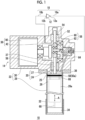
- Fig. 1 is a diagram schematically showing a cryocooler according to an embodiment.
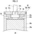
- Fig. 2 is a sectional view schematically showing a part (upper portion) of a first-stage displacer of the cryocooler shown in Fig. 1 .
- Figs. 3A and 3B are perspective views schematically showing an upper cap and a piston seal of the first-stage displacer shown in Fig. 2 , respectively.
- a cryocooler 10 includes a compressor 12 that compresses a working gas (also referred to as a refrigerant gas) and an expander 14 that cools the working gas by adiabatic expansion.
- the working gas is, for example, a helium gas.
- the expander 14 is also referred to as a cold head.
- the cryocooler 10 includes a gas pipe 18 that includes a first pipe 18a and a second pipe 18b, which connect the compressor 12 and the expander 14 to each other.
- the cryocooler 10 shown in the drawing is a single-stage GM cryocooler.
- the working gas having a first high pressure is supplied from a discharge port 12a of the compressor 12 to the expander 14 through the first pipe 18a. Due to the adiabatic expansion in the expander 14, the working gas is depressurized from the first high pressure to a second high pressure lower than the first high pressure.
- the working gas having the second high pressure is recovered from the expander 14 to a suction port 12b of the compressor 12 through the second pipe 18b.
- the compressor 12 compresses the recovered working gas having the second high pressure. In this way, the working gas is raised in pressure to the first high pressure again.
- both the first high pressure and the second high pressure are significantly higher than the atmospheric pressure.
- the first high pressure and the second high pressure are also simply referred to as high pressure and low pressure, respectively.
- the high pressure is, for example, in a range of 2 to 3 MPa
- the low pressure is, for example, in a range of 0.5 to 1.5 MPa
- a differential pressure between the high pressure and the low pressure is, for example, in a range of about 1.2 to 2 MPa.
- the expander 14 includes an expander movable portion 20 and an expander stationary portion 22.
- the axial direction represents a movement direction (an up-down direction in Fig. 1 ) of the expander movable portion 20 with respect to the expander stationary portion 22, as shown by an arrow A.
- the radial direction represents a direction (a lateral direction in the drawing) perpendicular to the axial direction
- the circumferential direction represents a direction surrounding the axial direction.
- the expander movable portion 20 is configured to be capable of reciprocating in the axial direction with respect to the expander stationary portion 22, and the expander stationary portion 22 is configured to support the expander movable portion 20 to be capable of reciprocating in the axial direction.
- the expander stationary portion 22 is configured as a hermetic container that accommodates the expander movable portion 20 together with a high-pressure gas (including a first high-pressure gas and a second high-pressure gas) .
- the expander movable portion 20 includes a first-stage displacer (hereinafter, also simply referred to as a displacer) 24 and a displacer drive shaft 27 that drives the reciprocating movement of the displacer 24.
- the displacer 24 includes an upper cap 25 and a displacer main body 26, and is connected to the displacer drive shaft 27 via the upper cap 25.
- the upper cap 25 of the displacer 24 is an upper lid of the displacer 24, and is attached to an upper end of the displacer main body 26.
- the upper cap 25 has a disk shape and is formed of a metal material or another material.
- the upper cap 25 may be formed of an aluminum alloy subjected to alumite treatment.
- the upper cap 25 may be formed of stainless steel.
- the upper cap 25 and the displacer main body 26 may be fixed to each other by, for example, a fastening member such as a bolt (or by other methods such as bonding).
- a piston seal 50 is mounted on a side surface (an outer peripheral surface) of the upper cap 25.
- the displacer main body 26 includes a regenerator material 26a and a displacer cylinder 26b.
- the regenerator material 26a may be formed by laminating a large number of circular wire meshes formed of a high heat conductive metal material such as copper (for example, pure copper) in the axial direction.
- the displacer cylinder 26b is a container that accommodates the regenerator material 26a, and has a cylindrical shape extending in the axial direction.
- the outer diameter of the displacer cylinder 26b is equal to the outer diameter of the upper cap 25, and the cylindrical outer shape of the displacer 24 is defined by the upper cap 25 and the displacer cylinder 26b.
- the displacer cylinder 26b is formed of a synthetic resin material or another material.
- the displacer cylinder 26b may be formed of, for example, a cloth-filled phenol resin.
- the displacer main body 26 includes a displacer inner lid 26c that is fixed to the displacer cylinder 26b so as to press the regenerator material 26a in the axial direction.
- the displacer inner lid 26c is disposed at an end portion of the displacer cylinder 26b, and is accommodated in the displacer cylinder 26b together with the regenerator material 26a.
- the displacer inner lid 26c may be fixed to the displacer cylinder 26b by a fixing pin 26d penetrating the displacer cylinder 26b in the radial direction from the outer peripheral surface of the displacer cylinder 26b.
- a flow straightening layer formed of at least one wire mesh having a different wire diameter and/or mesh from the wire mesh as the regenerator material 26a may be provided between the displacer inner lid 26c and the regenerator material 26a.
- a collar portion 27a extending to the radial outer side is attached to a tip (a lower end in the axial direction) of the displacer drive shaft 27.
- the collar portion 27a has a circular shape having a diameter larger the diameter of the shaft when viewed in the axial direction of the shaft.
- the displacer drive shaft 27 and the collar portion 27a may be connected to each other by a connecting pin 27b penetrating the displacer drive shaft 27 and the collar portion 27a in the radial direction.
- the displacer drive shaft 27, the collar portion 27a, and the connecting pin 27b are formed of a metal material such as stainless steel, for example, or another material.
- An insertion hole 44 through which the displacer drive shaft 27 passes is formed at the center of the upper cap 25, and a center hole 46 that receives the collar portion 27a is formed in the displacer inner lid 26c.
- the displacer drive shaft 27 is connected to the displacer 24 by sandwiching the collar portion 27a between the upper cap 25 and the displacer inner lid 26c.
- the expander stationary portion 22 has a two-part configuration roughly composed of an expander cylinder 28 and a drive mechanism housing 30.
- An axial upper portion of the expander stationary portion 22 is the drive mechanism housing 30, an axial lower portion of the expander stationary portion 22 is the expander cylinder 28, and the drive mechanism housing 30 and the expander cylinder 28 are tightly coupled to each other.
- the expander cylinder 28 is configured to extend in the axial direction from the drive mechanism housing 30 and to guide the reciprocating movement of the displacer 24.
- the expander cylinder 28 has a substantially uniform inner diameter in the axial direction, and thus, the expander cylinder 28 has a substantially cylindrical inner surface extending in the axial direction. The inner diameter is slightly larger than the outer diameter of the displacer 24.
- the expander stationary portion 22 includes a cryocooler stage 32.
- the cryocooler stage 32 is fixed to the end of the expander cylinder 28 on a side opposite to the drive mechanism housing 30 in the axial direction.
- the cryocooler stage 32 is provided to conduct the coldness generated by the expander 14 to another object.
- the object is attached to the cryocooler stage 32 and is cooled by the cryocooler stage 32 when the cryocooler 10 is operated.
- the cryocooler stage 32 is also sometimes referred to as a cooling stage or a heat load stage.
- the cryocooler 10 is typically installed with the cryocooler stage 32 facing downward and the drive mechanism housing 30 facing upward, as shown in Fig. 1 .
- the cryocooler 10 may be installed in another posture, and for example, the cryocooler 10 may be installed with the cryocooler stage 32 facing upward and the drive mechanism housing 30 facing downward.
- the expander 14 may be installed such that the axial direction thereof coincides with the horizontal direction.
- the expander cylinder 28 is partitioned into an expansion space 34 and an upper space 36 by the displacer 24.
- the displacer 24 defines the expansion space 34 at the end portion of the expander cylinder 28 on the cryocooler stage 32 side, and defines the upper space 36 at the end portion of the expander cylinder 28 on the drive mechanism housing 30 side.
- the volumes of the expansion space 34 and the upper space 36 are complementarily varied by the relative movement of the displacer 24 with respect to the expander cylinder 28.
- the expansion space 34 has a maximum volume at the top dead center of the displacer 24, and has a minimum volume at the bottom dead center of the displacer 24.
- the upper space 36 has a minimum volume at the top dead center of the displacer 24 and has a maximum volume at the bottom dead center of the displacer 24.
- the expander 14 When the cryocooler 10 is operated, the expander 14 has an axial temperature distribution in which the upper space 36 is a high-temperature portion and the expansion space 34 is a low-temperature portion.
- the high-temperature portion has, for example, a temperature of about room temperature.
- the low-temperature portion is cooled to a certain temperature included in a range of, for example, about 100 K to about 10 K, although it is different depending on the use of the cryocooler 10.
- the expander 14 includes a displacer drive mechanism 38 that is supported by the expander stationary portion 22 and drives the displacer 24.
- the displacer drive mechanism 38 includes a motor 40 such as an electric motor, for example, and a Scotch yoke mechanism 42.
- the displacer drive mechanism 38 is accommodated in a low-pressure gas chamber 37 that is defined inside the drive mechanism housing 30 adjacent to the upper space 36.
- the second pipe 18b is connected to the drive mechanism housing 30, and thereby, the low-pressure gas chamber 37 communicates with a suction port 12b of the compressor 12 through the second pipe 18b. Therefore, the low-pressure gas chamber 37 is always maintained at low pressure.
- the displacer drive shaft 27 is connected to the Scotch yoke mechanism 42 so as to be driven in the axial direction by the Scotch yoke mechanism 42, and forms a part of the Scotch yoke mechanism 42.
- the displacer drive shaft 27 extends from the low-pressure gas chamber 37 to the displacer 24 by penetrating the upper space 36.
- the displacer drive shaft 27 has a diameter smaller than the diameter of the displacer 24, and for example, the diameter of the displacer drive shaft 27 is smaller than half of the diameter of the displacer 24.
- a first sliding bearing 54 and a second sliding bearing 56 are provided in the drive mechanism housing 30 of the expander stationary portion 22.
- An upper rod 52 of the Scotch yoke mechanism 42 is supported by the first sliding bearing 54 to be movable in the axial direction, and the displacer drive shaft 27 is supported by the second sliding bearing 56 to be movable in the axial direction. Therefore, the upper rod 52, the displacer drive shaft 27, and the Scotch yoke mechanism 42 are configured to be movable in the axial direction.
- a seal portion such as a slipper seal or a clearance seal, for example, is provided at a lower end portion of the second sliding bearing 56 or the drive mechanism housing 30, and is configured to be airtight. Therefore, the low-pressure gas chamber 37 is isolated from the upper space 36. There is no direct gas flow between the low-pressure gas chamber 37 and the upper space 36.
- the Scotch yoke mechanism 42 reciprocates in the axial direction by the rotation of an output shaft of the motor 40. Therefore, the Scotch yoke mechanism 42 moves in the axial direction, so that the displacer 24 reciprocates in the axial direction in the expander cylinder 28.
- the expander 14 includes a rotary valve 58 configured to switch between the intake and the exhaust of the expansion space 34 in synchronization with the axial reciprocation of the displacer 24 by the rotation of the motor 40, and thereby to control the pressure of the expansion space 34.
- the rotary valve 58 includes a rotor valve member 60 supported to be rotatable in the drive mechanism housing 30, and a stator valve member 62 fixed inside the drive mechanism housing 30.
- the rotor valve member 60 is connected to a rotary shaft of the motor 40, and rotates with respect to the stator valve member 62 by the rotation of the rotary shaft.
- the rotor valve member 60 is in surface contact with the stator valve member 62 so as to rotate and slide with respect to the stator valve member 62.
- the stator valve member 62 is configured to receive the high-pressure gas entering the drive mechanism housing 30 from the first pipe 18a.
- the intake and the exhaust of the expansion space 34 can be switched by the rotation of the rotor valve member 60 with respect to the stator valve member 62. Since various known flow path configurations can be adopted for the rotary valve 58, the flow path configuration will not be described in detail.
- a housing gas flow path 64 for a gas flow between the rotary valve 58 and the upper space 36 is formed in the drive mechanism housing 30.
- a displacer upper lid gas flow path 66 is formed in an upper end portion of the displacer 24 for a gas flow between the upper space 36 and the regenerator material 26a in the displacer 24.
- the displacer upper lid gas flow path 66 may be formed to penetrate the upper cap 25 and the displacer inner lid 26c.
- a displacer lower lid gas flow path 68 is formed in a lower end portion of the displacer 24 for a gas flow between the expansion space 34 and the regenerator material 26a in the displacer 24.
- Figs. 3A and 3B are perspective views schematically showing the upper cap 25 and the piston seal 50, respectively.
- the piston seal 50 is mounted on the upper cap 25.
- the piston seal 50 includes a piston ring 50a and a tension ring 50b adjacent to the radial inner side of the piston ring 50a.
- the piston ring 50a is formed of, for example, a fluororesin such as polytetrafluoroethylene, or another synthetic resin material having excellent sliding properties and/or durability.
- the tension ring 50b is formed of a metal material such as stainless steel, for example, or other materials.
- the piston seal 50 is fitted into a peripheral groove formed on the side surface of the upper cap 25, and is held by the upper cap 25.
- the piston ring 50a on the radial outer side is pressed against the inner peripheral surface of the expander cylinder 28 by the tension of the tension ring 50b on the radial inner side.
- the piston ring 50a slides on the inner peripheral surface of the expander cylinder 28 when the displacer 24 reciprocates in the axial direction. In this way, the clearance between the outer peripheral surface of the displacer 24 and the inner peripheral surface of the expander cylinder 28 is sealed by the piston seal 50, and a direct gas flow between the upper space 36 and the expansion space 34 through the clearance (that is, a gas flow that bypasses the regenerator material 26a) is blocked.
- Fig. 3A there are shows the insertion hole 44, the displacer upper lid gas flow path 66, and a bolt hole 48, which penetrate the upper cap 25 in the axial direction.
- the insertion hole 44 is formed at the center of the upper cap 25 to receive the displacer drive shaft 27.
- a plurality of the displacer upper lid gas flow paths 66 are provided to surround the insertion hole 44, and are disposed at equal angular intervals in the circumferential direction.
- the four displacer upper lid gas flow paths 66 are provided in the upper cap 25.
- the bolt holes 48 are also provided to surround the insertion hole 44, and are disposed at equal angular intervals in the circumferential direction.
- the four bolt holes 48 are disposed alternately with the displacer upper lid gas flow path 66 in the circumferential direction at the same radial position as the displacer upper lid gas flow path 66.
- the configuration of the cryocooler 10 according to the embodiment has been described above. Next, the operation of the cryocooler 10 will be described.
- the rotary valve 58 is switched to connect a discharge port 12a of the compressor 12 to the expansion space 34, and an intake process of the refrigeration cycle is started.
- the high-pressure gas flows from the rotary valve 58 to the regenerator material 26a in the displacer 24 through the housing gas flow path 64, the upper space 36, and the displacer upper lid gas flow path 66.
- the gas is cooled while passing through the regenerator material 26a, and enters the expansion space 34 through the displacer lower lid gas flow path 68.
- the displacer 24 moves upward in the axial direction in the expander cylinder 28 from the bottom dead center toward the top dead center by the displacer drive shaft 27. Accordingly, the volume of the expansion space 34 is increased. In this way, the expansion space 34 is filled with the high-pressure gas.
- the rotary valve 58 When the displacer 24 is at or in the vicinity of the top dead center, the rotary valve 58 is switched to connect the suction port 12b of the compressor 12 to the expansion space 34, and an exhaust process of the refrigeration cycle is started. At this time, the high-pressure gas in the expansion space 34 expands and is cooled. The expanded gas flows from the expansion space 34 into the regenerator material 26a in the displacer 24 through the displacer lower lid gas flow path 68. The gas is cooled while passing through the regenerator material 26a. The gas returns from the regenerator material 26a to the compressor 12 through the upper space 36, the housing gas flow path 64, the rotary valve 58, and the low-pressure gas chamber 37.
- the displacer 24 moves downward in the axial direction from the top dead center toward the bottom dead center in the expander cylinder 28 by the displacer drive shaft 27. Accordingly, the volume of the expansion space 34 is reduced, and the low-pressure gas is discharged from the expansion space 34.
- the intake process is started again.
- the above is one refrigeration cycle in the cryocooler 10.
- the cryocooler 10 cools the cryocooler stage 32 to a desired temperature by repeating the refrigeration cycle. Therefore, the cryocooler 10 can cool an object thermally coupled to the cryocooler stage 32 to a cryogenic temperature.
- a sealing member provided at an upper end portion of the first-stage displacer is mounted on a tubular portion of the first-stage displacer, that is, a peripheral groove formed in a portion of a synthetic resin material such as a cloth-filled phenol resin.
- a sealing member provided at an upper end portion of the first-stage displacer is mounted on a tubular portion of the first-stage displacer, that is, a peripheral groove formed in a portion of a synthetic resin material such as a cloth-filled phenol resin.
- the sealing member In a case where the groove dimension exceeds the allowable range in the design, a gas may leak between the groove and the sealing member, and the sealing performance may be lowered. On the contrary, in a case where the groove is narrowed, the sealing member strongly adheres to the surface of the synthetic resin material in the groove, so that the pushing force from the sealing member to the cylinder is weakened, and a gas may leak at the contact surface between the sealing member and the cylinder.
- the first-stage displacer is incorporated in the GM cryocooler, and is then used for a long period of time, so that the sealing performance may be lowered due to the abrasion of the sealing member.
- the piston seal 50 is mounted on the upper cap 25 made of metal.
- the upper cap 25 made of metal it is easier to process the peripheral groove with high accuracy, compared to the displacer cylinder 26b made of a synthetic resin material.
- the upper cap 25 made of metal is unlikely to change in groove dimension. Therefore, the sealing performance of the first-stage displacer of the GM cryocooler can be stably maintained for a long period of time.
- a combination of a sealing ring, which is also referred to as a slipper seal, and an O-ring is often used as a sealing member at the upper end of the first-stage displacer.
- the sealing ring is pressed against the inner peripheral surface of the cylinder by an elastic restoring force outward in the radial direction from the O-ring compressed in the radial direction.
- the sealing ring is abraded due to long-term use and the radial thickness thereof is reduced, the pushing force from the O-ring against the sealing ring is also weakened, and the sealing performance may be lowered.
- the piston seal 50 is used. Compared to the slipper seal, the sealing performance of the piston seal 50 is less likely to be affected by abrasion due to long-term use. This also helps to stabilize the sealing performance of the first-stage displacer in the long term.
- Fig. 4 is a perspective view schematically showing another example of the upper cap 25 of the displacer 24.
- a plurality of piston seals 50 may be mounted on the side surface (the outer peripheral surface) of the upper cap 25.
- two piston seals 50 are disposed in the axial direction (up and down in the drawing).
- a plurality of peripheral grooves are formed in the side surface of the upper cap 25, and each piston seal 50 is fitted into a corresponding peripheral groove, as with the embodiment described above. In this manner, the plurality of piston seals 50 are provided, so that the sealing performance can be further enhanced.
- Fig. 5 is a sectional view schematically showing another example of a part (upper portion) of the displacer 24.
- the displacer 24 may include an additional sealing member 70 that is mounted between the upper cap 25 and the displacer cylinder 26b.
- the sealing member 70 may be a so-called slipper seal that includes a sealing ring 70a and a back ring 70b adjacent to the radial inner side of the sealing ring 70a.
- the sealing ring 70a is formed of, for example, a fluororesin such as polytetrafluoroethylene, or another synthetic resin material having excellent sliding properties and/or durability.
- the back ring 70b may be, for example, an O-ring or another ring made of synthetic rubber.
- the sealing member 70 may be, for example, another contact seal such as an O-ring, instead of the slipper seal.
- the sealing member 70 is accommodated in a peripheral groove formed in the upper end of the displacer cylinder 26b, and is sandwiched between the upper cap 25 and the displacer cylinder 26b.
- the sealing ring 70a is pressed against the inner peripheral surface of the expander cylinder 28 by the back ring 70b, and the sealing member 70 can seal a gas between the outer peripheral surface of the displacer 24 and the inner peripheral surface of the expander cylinder 28. In this manner, the sealing member 70 is added, so that the sealing performance can be further enhanced.
- the embodiment has been described with reference to the single-stage GM cryocooler.
- the present invention is not limited thereto, and the seal structure according to the embodiment is also applicable to a first-stage displacer of a two-stage or multi-stage GM cryocooler.
- the present invention can be used in the field of Gifford-McMahon (GM) cryocoolers.
- GM Gifford-McMahon
Landscapes
- Engineering & Computer Science (AREA)
- General Engineering & Computer Science (AREA)
- Mechanical Engineering (AREA)
- Physics & Mathematics (AREA)
- Thermal Sciences (AREA)
- Compressors, Vaccum Pumps And Other Relevant Systems (AREA)
Abstract
Description
- The present invention relates to a first-stage displacer of a Gifford-McMahon (GM) cryocooler, and a Gifford-McMahon cryocooler provided with the first-stage displacer.
- In general, a sealing member is mounted on an upper end portion of a first-stage displacer of a GM cryocooler in order to prevent a refrigerant gas from leaking through a gap between a displacer and a cylinder.
- [PTL 1]
Japanese Unexamined Patent Publication No. 2007-205608 - A first-stage displacer of the GM cryocooler is usually formed of a synthetic resin material such as a cloth-filled phenol resin, and a sealing member is fitted into a peripheral groove carved in the synthetic resin material. The sealing member can provide desired sealing performance by bringing the clearance between the sealing member and the groove within a range defined in the design.
- The first-stage displacer may be stored in an inappropriate environment. In this case, the dimensions of the peripheral groove, such as a width or a depth, may change due to various factors such as water absorption or a temperature change in the synthetic resin material. In a case where the groove dimension exceeds the allowable range, a gas may leak between the groove and the sealing member, and the sealing performance may be lowered. On the contrary, in a case where the groove is narrowed, the sealing member strongly adheres to the surface of the synthetic resin material in the groove, so that the pushing force from the sealing member to the cylinder is weakened, and a gas may leak at the contact surface between the sealing member and the cylinder.
- One exemplary object of an aspect of the present invention is to stabilize the sealing performance of a first-stage displacer of a GM cryocooler.
- An aspect of the present invention relates to a first-stage displacer of a Gifford-McMahon (GM) cryocooler. The first-stage displacer includes: a first-stage displacer main body; a metal upper cap attached to an upper end of the first-stage displacer main body and formed of a metal material; and at least one piston seal mounted on a side surface of the metal upper cap.
- Another aspect of the present invention relates to a GM cryocooler. The GM cryocooler includes: the first-stage displacer according to the above aspect.
- Another aspect of the present invention relates to a first-stage displacer assembly of a Gifford-McMahon (GM) cryocooler. The first-stage displacer assembly includes: a displacer drive shaft; and the first-stage displacer according to the above aspect. A metal upper cap is attached to the upper end of a first-stage displacer main body such that the displacer drive shaft is connected to the first-stage displacer.
- Another aspect of the present invention relates to a GM cryocooler. The GM cryocooler includes: the first-stage displacer assembly according to the above aspect.
- According to the present invention, it is possible to stabilize the sealing performance of the first-stage displacer of the GM cryocooler.
-
-
Fig. 1 is a diagram schematically showing a cryocooler according to an embodiment. -
Fig. 2 is a sectional view schematically showing a part (upper portion) of a first-stage displacer of the cryocooler shown inFig. 1 . -
Figs. 3A and 3B are perspective views schematically showing an upper cap and a piston seal of the first-stage displacer shown inFig. 2 , respectively. -
Fig. 4 is a perspective view schematically showing another example of the upper cap of the first-stage displacer. -
Fig. 5 is a sectional view schematically showing another example of the part (upper portion) of the first-stage displacer. - Hereinafter, embodiments for carrying out the present invention will be described in detail with reference to the drawings. In the description and drawings, identical or equivalent components, members, and processing are denoted by the same reference numerals, and overlapping description is omitted as appropriate. The scale or shape of each part that is shown in the drawings is conveniently set for ease of description and is not limitedly interpreted unless otherwise specified. The embodiments are exemplary and do not limit the scope of the present invention in any way. All features or combinations thereof described in the embodiments are not essential to the invention.
-
Fig. 1 is a diagram schematically showing a cryocooler according to an embodiment.Fig. 2 is a sectional view schematically showing a part (upper portion) of a first-stage displacer of the cryocooler shown inFig. 1 .Figs. 3A and 3B are perspective views schematically showing an upper cap and a piston seal of the first-stage displacer shown inFig. 2 , respectively. - A
cryocooler 10 includes acompressor 12 that compresses a working gas (also referred to as a refrigerant gas) and anexpander 14 that cools the working gas by adiabatic expansion. The working gas is, for example, a helium gas. Theexpander 14 is also referred to as a cold head. Thecryocooler 10 includes agas pipe 18 that includes afirst pipe 18a and asecond pipe 18b, which connect thecompressor 12 and the expander 14 to each other. Thecryocooler 10 shown in the drawing is a single-stage GM cryocooler. - As is known, the working gas having a first high pressure is supplied from a
discharge port 12a of thecompressor 12 to theexpander 14 through thefirst pipe 18a. Due to the adiabatic expansion in theexpander 14, the working gas is depressurized from the first high pressure to a second high pressure lower than the first high pressure. The working gas having the second high pressure is recovered from theexpander 14 to asuction port 12b of thecompressor 12 through thesecond pipe 18b. Thecompressor 12 compresses the recovered working gas having the second high pressure. In this way, the working gas is raised in pressure to the first high pressure again. In general, both the first high pressure and the second high pressure are significantly higher than the atmospheric pressure. For convenience of description, the first high pressure and the second high pressure are also simply referred to as high pressure and low pressure, respectively. In general, the high pressure is, for example, in a range of 2 to 3 MPa, and the low pressure is, for example, in a range of 0.5 to 1.5 MPa. A differential pressure between the high pressure and the low pressure is, for example, in a range of about 1.2 to 2 MPa. - The
expander 14 includes an expandermovable portion 20 and an expanderstationary portion 22. In the present specification, for convenience of description, terms of an axial direction, a radial direction, and a circumferential direction are used. The axial direction represents a movement direction (an up-down direction inFig. 1 ) of the expandermovable portion 20 with respect to the expanderstationary portion 22, as shown by an arrow A. The radial direction represents a direction (a lateral direction in the drawing) perpendicular to the axial direction, and the circumferential direction represents a direction surrounding the axial direction. Therefore, the expandermovable portion 20 is configured to be capable of reciprocating in the axial direction with respect to the expanderstationary portion 22, and the expanderstationary portion 22 is configured to support the expandermovable portion 20 to be capable of reciprocating in the axial direction. In addition, the expanderstationary portion 22 is configured as a hermetic container that accommodates the expandermovable portion 20 together with a high-pressure gas (including a first high-pressure gas and a second high-pressure gas) . - The expander
movable portion 20 includes a first-stage displacer (hereinafter, also simply referred to as a displacer) 24 and adisplacer drive shaft 27 that drives the reciprocating movement of thedisplacer 24. Thedisplacer 24 includes anupper cap 25 and a displacermain body 26, and is connected to thedisplacer drive shaft 27 via theupper cap 25. - The
upper cap 25 of thedisplacer 24 is an upper lid of thedisplacer 24, and is attached to an upper end of the displacermain body 26. Theupper cap 25 has a disk shape and is formed of a metal material or another material. Theupper cap 25 may be formed of an aluminum alloy subjected to alumite treatment. Theupper cap 25 may be formed of stainless steel. Theupper cap 25 and the displacermain body 26 may be fixed to each other by, for example, a fastening member such as a bolt (or by other methods such as bonding). - Although details will be described later, a
piston seal 50 is mounted on a side surface (an outer peripheral surface) of theupper cap 25. - As shown in
Fig. 2 , the displacermain body 26 includes aregenerator material 26a and adisplacer cylinder 26b. Theregenerator material 26a may be formed by laminating a large number of circular wire meshes formed of a high heat conductive metal material such as copper (for example, pure copper) in the axial direction. Thedisplacer cylinder 26b is a container that accommodates theregenerator material 26a, and has a cylindrical shape extending in the axial direction. The outer diameter of thedisplacer cylinder 26b is equal to the outer diameter of theupper cap 25, and the cylindrical outer shape of thedisplacer 24 is defined by theupper cap 25 and thedisplacer cylinder 26b. Thedisplacer cylinder 26b is formed of a synthetic resin material or another material. Thedisplacer cylinder 26b may be formed of, for example, a cloth-filled phenol resin. - In addition, the displacer
main body 26 includes a displacer inner lid 26c that is fixed to thedisplacer cylinder 26b so as to press theregenerator material 26a in the axial direction. The displacer inner lid 26c is disposed at an end portion of thedisplacer cylinder 26b, and is accommodated in thedisplacer cylinder 26b together with theregenerator material 26a. The displacer inner lid 26c may be fixed to thedisplacer cylinder 26b by a fixing pin 26d penetrating thedisplacer cylinder 26b in the radial direction from the outer peripheral surface of thedisplacer cylinder 26b. A flow straightening layer formed of at least one wire mesh having a different wire diameter and/or mesh from the wire mesh as theregenerator material 26a may be provided between the displacer inner lid 26c and theregenerator material 26a. - A
collar portion 27a extending to the radial outer side is attached to a tip (a lower end in the axial direction) of thedisplacer drive shaft 27. Thecollar portion 27a has a circular shape having a diameter larger the diameter of the shaft when viewed in the axial direction of the shaft. Thedisplacer drive shaft 27 and thecollar portion 27a may be connected to each other by a connectingpin 27b penetrating thedisplacer drive shaft 27 and thecollar portion 27a in the radial direction. Thedisplacer drive shaft 27, thecollar portion 27a, and the connectingpin 27b are formed of a metal material such as stainless steel, for example, or another material. - An
insertion hole 44 through which thedisplacer drive shaft 27 passes is formed at the center of theupper cap 25, and acenter hole 46 that receives thecollar portion 27a is formed in the displacer inner lid 26c. Thedisplacer drive shaft 27 is connected to thedisplacer 24 by sandwiching thecollar portion 27a between theupper cap 25 and the displacer inner lid 26c. - As shown in
Fig. 1 , the expanderstationary portion 22 has a two-part configuration roughly composed of anexpander cylinder 28 and adrive mechanism housing 30. An axial upper portion of the expanderstationary portion 22 is thedrive mechanism housing 30, an axial lower portion of the expanderstationary portion 22 is theexpander cylinder 28, and thedrive mechanism housing 30 and theexpander cylinder 28 are tightly coupled to each other. Theexpander cylinder 28 is configured to extend in the axial direction from thedrive mechanism housing 30 and to guide the reciprocating movement of thedisplacer 24. Theexpander cylinder 28 has a substantially uniform inner diameter in the axial direction, and thus, theexpander cylinder 28 has a substantially cylindrical inner surface extending in the axial direction. The inner diameter is slightly larger than the outer diameter of thedisplacer 24. - In addition, the expander
stationary portion 22 includes acryocooler stage 32. Thecryocooler stage 32 is fixed to the end of theexpander cylinder 28 on a side opposite to thedrive mechanism housing 30 in the axial direction. Thecryocooler stage 32 is provided to conduct the coldness generated by theexpander 14 to another object. The object is attached to thecryocooler stage 32 and is cooled by thecryocooler stage 32 when thecryocooler 10 is operated. Thecryocooler stage 32 is also sometimes referred to as a cooling stage or a heat load stage. - The
cryocooler 10 is typically installed with thecryocooler stage 32 facing downward and thedrive mechanism housing 30 facing upward, as shown inFig. 1 . However, thecryocooler 10 may be installed in another posture, and for example, thecryocooler 10 may be installed with thecryocooler stage 32 facing upward and thedrive mechanism housing 30 facing downward. Alternatively, theexpander 14 may be installed such that the axial direction thereof coincides with the horizontal direction. - The
expander cylinder 28 is partitioned into anexpansion space 34 and anupper space 36 by thedisplacer 24. Thedisplacer 24 defines theexpansion space 34 at the end portion of theexpander cylinder 28 on thecryocooler stage 32 side, and defines theupper space 36 at the end portion of theexpander cylinder 28 on thedrive mechanism housing 30 side. The volumes of theexpansion space 34 and theupper space 36 are complementarily varied by the relative movement of thedisplacer 24 with respect to theexpander cylinder 28. Theexpansion space 34 has a maximum volume at the top dead center of thedisplacer 24, and has a minimum volume at the bottom dead center of thedisplacer 24. Theupper space 36 has a minimum volume at the top dead center of thedisplacer 24 and has a maximum volume at the bottom dead center of thedisplacer 24. - When the
cryocooler 10 is operated, theexpander 14 has an axial temperature distribution in which theupper space 36 is a high-temperature portion and theexpansion space 34 is a low-temperature portion. The high-temperature portion has, for example, a temperature of about room temperature. The low-temperature portion is cooled to a certain temperature included in a range of, for example, about 100 K to about 10 K, although it is different depending on the use of thecryocooler 10. - The
expander 14 includes a displacer drive mechanism 38 that is supported by the expanderstationary portion 22 and drives thedisplacer 24. The displacer drive mechanism 38 includes amotor 40 such as an electric motor, for example, and a Scotch yoke mechanism 42. The displacer drive mechanism 38 is accommodated in a low-pressure gas chamber 37 that is defined inside thedrive mechanism housing 30 adjacent to theupper space 36. Thesecond pipe 18b is connected to thedrive mechanism housing 30, and thereby, the low-pressure gas chamber 37 communicates with asuction port 12b of thecompressor 12 through thesecond pipe 18b. Therefore, the low-pressure gas chamber 37 is always maintained at low pressure. - The
displacer drive shaft 27 is connected to the Scotch yoke mechanism 42 so as to be driven in the axial direction by the Scotch yoke mechanism 42, and forms a part of the Scotch yoke mechanism 42. Thedisplacer drive shaft 27 extends from the low-pressure gas chamber 37 to thedisplacer 24 by penetrating theupper space 36. Thedisplacer drive shaft 27 has a diameter smaller than the diameter of thedisplacer 24, and for example, the diameter of thedisplacer drive shaft 27 is smaller than half of the diameter of thedisplacer 24. - A first sliding
bearing 54 and a second sliding bearing 56 are provided in thedrive mechanism housing 30 of the expanderstationary portion 22. Anupper rod 52 of the Scotch yoke mechanism 42 is supported by the first slidingbearing 54 to be movable in the axial direction, and thedisplacer drive shaft 27 is supported by the second sliding bearing 56 to be movable in the axial direction. Therefore, theupper rod 52, thedisplacer drive shaft 27, and the Scotch yoke mechanism 42 are configured to be movable in the axial direction. - A seal portion such as a slipper seal or a clearance seal, for example, is provided at a lower end portion of the second sliding bearing 56 or the
drive mechanism housing 30, and is configured to be airtight. Therefore, the low-pressure gas chamber 37 is isolated from theupper space 36. There is no direct gas flow between the low-pressure gas chamber 37 and theupper space 36. - The Scotch yoke mechanism 42 reciprocates in the axial direction by the rotation of an output shaft of the
motor 40. Therefore, the Scotch yoke mechanism 42 moves in the axial direction, so that thedisplacer 24 reciprocates in the axial direction in theexpander cylinder 28. - The
expander 14 includes arotary valve 58 configured to switch between the intake and the exhaust of theexpansion space 34 in synchronization with the axial reciprocation of thedisplacer 24 by the rotation of themotor 40, and thereby to control the pressure of theexpansion space 34. Therotary valve 58 includes arotor valve member 60 supported to be rotatable in thedrive mechanism housing 30, and astator valve member 62 fixed inside thedrive mechanism housing 30. Therotor valve member 60 is connected to a rotary shaft of themotor 40, and rotates with respect to thestator valve member 62 by the rotation of the rotary shaft. Therotor valve member 60 is in surface contact with thestator valve member 62 so as to rotate and slide with respect to thestator valve member 62. Thestator valve member 62 is configured to receive the high-pressure gas entering thedrive mechanism housing 30 from thefirst pipe 18a. The intake and the exhaust of theexpansion space 34 can be switched by the rotation of therotor valve member 60 with respect to thestator valve member 62. Since various known flow path configurations can be adopted for therotary valve 58, the flow path configuration will not be described in detail. - A housing
gas flow path 64 for a gas flow between therotary valve 58 and theupper space 36 is formed in thedrive mechanism housing 30. In addition, a displacer upper lidgas flow path 66 is formed in an upper end portion of thedisplacer 24 for a gas flow between theupper space 36 and theregenerator material 26a in thedisplacer 24. The displacer upper lidgas flow path 66 may be formed to penetrate theupper cap 25 and the displacer inner lid 26c. A displacer lower lidgas flow path 68 is formed in a lower end portion of thedisplacer 24 for a gas flow between theexpansion space 34 and theregenerator material 26a in thedisplacer 24. -
Figs. 3A and 3B are perspective views schematically showing theupper cap 25 and thepiston seal 50, respectively. In this embodiment, as described above, thepiston seal 50 is mounted on theupper cap 25. - As shown in
Figs. 2 ,3A, and 3B , thepiston seal 50 includes apiston ring 50a and atension ring 50b adjacent to the radial inner side of thepiston ring 50a. Thepiston ring 50a is formed of, for example, a fluororesin such as polytetrafluoroethylene, or another synthetic resin material having excellent sliding properties and/or durability. Thetension ring 50b is formed of a metal material such as stainless steel, for example, or other materials. - The
piston seal 50 is fitted into a peripheral groove formed on the side surface of theupper cap 25, and is held by theupper cap 25. Thepiston ring 50a on the radial outer side is pressed against the inner peripheral surface of theexpander cylinder 28 by the tension of thetension ring 50b on the radial inner side. Thepiston ring 50a slides on the inner peripheral surface of theexpander cylinder 28 when thedisplacer 24 reciprocates in the axial direction. In this way, the clearance between the outer peripheral surface of thedisplacer 24 and the inner peripheral surface of theexpander cylinder 28 is sealed by thepiston seal 50, and a direct gas flow between theupper space 36 and theexpansion space 34 through the clearance (that is, a gas flow that bypasses theregenerator material 26a) is blocked. - In
Fig. 3A , there are shows theinsertion hole 44, the displacer upper lidgas flow path 66, and abolt hole 48, which penetrate theupper cap 25 in the axial direction. As described above, theinsertion hole 44 is formed at the center of theupper cap 25 to receive thedisplacer drive shaft 27. A plurality of the displacer upper lidgas flow paths 66 are provided to surround theinsertion hole 44, and are disposed at equal angular intervals in the circumferential direction. In this example, the four displacer upper lidgas flow paths 66 are provided in theupper cap 25. The bolt holes 48 are also provided to surround theinsertion hole 44, and are disposed at equal angular intervals in the circumferential direction. In this example, the fourbolt holes 48 are disposed alternately with the displacer upper lidgas flow path 66 in the circumferential direction at the same radial position as the displacer upper lidgas flow path 66. - The configuration of the
cryocooler 10 according to the embodiment has been described above. Next, the operation of thecryocooler 10 will be described. When thedisplacer 24 is located at or in the vicinity of the bottom dead center, therotary valve 58 is switched to connect adischarge port 12a of thecompressor 12 to theexpansion space 34, and an intake process of the refrigeration cycle is started. The high-pressure gas flows from therotary valve 58 to theregenerator material 26a in thedisplacer 24 through the housinggas flow path 64, theupper space 36, and the displacer upper lidgas flow path 66. The gas is cooled while passing through theregenerator material 26a, and enters theexpansion space 34 through the displacer lower lidgas flow path 68. While the gas flows into theexpansion space 34, thedisplacer 24 moves upward in the axial direction in theexpander cylinder 28 from the bottom dead center toward the top dead center by thedisplacer drive shaft 27. Accordingly, the volume of theexpansion space 34 is increased. In this way, theexpansion space 34 is filled with the high-pressure gas. - When the
displacer 24 is at or in the vicinity of the top dead center, therotary valve 58 is switched to connect thesuction port 12b of thecompressor 12 to theexpansion space 34, and an exhaust process of the refrigeration cycle is started. At this time, the high-pressure gas in theexpansion space 34 expands and is cooled. The expanded gas flows from theexpansion space 34 into theregenerator material 26a in thedisplacer 24 through the displacer lower lidgas flow path 68. The gas is cooled while passing through theregenerator material 26a. The gas returns from theregenerator material 26a to thecompressor 12 through theupper space 36, the housinggas flow path 64, therotary valve 58, and the low-pressure gas chamber 37. While the gas flows out from theexpansion space 34, thedisplacer 24 moves downward in the axial direction from the top dead center toward the bottom dead center in theexpander cylinder 28 by thedisplacer drive shaft 27. Accordingly, the volume of theexpansion space 34 is reduced, and the low-pressure gas is discharged from theexpansion space 34. When the exhaust process is ended, the intake process is started again. - The above is one refrigeration cycle in the
cryocooler 10. Thecryocooler 10 cools thecryocooler stage 32 to a desired temperature by repeating the refrigeration cycle. Therefore, thecryocooler 10 can cool an object thermally coupled to thecryocooler stage 32 to a cryogenic temperature. - Incidentally, in an existing GM cryocooler, in general, a sealing member provided at an upper end portion of the first-stage displacer is mounted on a tubular portion of the first-stage displacer, that is, a peripheral groove formed in a portion of a synthetic resin material such as a cloth-filled phenol resin. For example, due to various factors such as water absorption or a temperature change in the synthetic resin material caused by the influence of a storage environment or the like of the first-stage displacer, the dimensions of the peripheral groove such as a width or a depth may change, and the sealing performance of the sealing member may be affected.
- In a case where the groove dimension exceeds the allowable range in the design, a gas may leak between the groove and the sealing member, and the sealing performance may be lowered. On the contrary, in a case where the groove is narrowed, the sealing member strongly adheres to the surface of the synthetic resin material in the groove, so that the pushing force from the sealing member to the cylinder is weakened, and a gas may leak at the contact surface between the sealing member and the cylinder.
- In addition, the first-stage displacer is incorporated in the GM cryocooler, and is then used for a long period of time, so that the sealing performance may be lowered due to the abrasion of the sealing member.
- According to the embodiment, the
piston seal 50 is mounted on theupper cap 25 made of metal. In theupper cap 25 made of metal, it is easier to process the peripheral groove with high accuracy, compared to thedisplacer cylinder 26b made of a synthetic resin material. In addition, even after long-term use, theupper cap 25 made of metal is unlikely to change in groove dimension. Therefore, the sealing performance of the first-stage displacer of the GM cryocooler can be stably maintained for a long period of time. - In addition, in the existing GM cryocooler, a combination of a sealing ring, which is also referred to as a slipper seal, and an O-ring is often used as a sealing member at the upper end of the first-stage displacer. The sealing ring is pressed against the inner peripheral surface of the cylinder by an elastic restoring force outward in the radial direction from the O-ring compressed in the radial direction. As the sealing ring is abraded due to long-term use and the radial thickness thereof is reduced, the pushing force from the O-ring against the sealing ring is also weakened, and the sealing performance may be lowered.
- In contrast, in the embodiment, the
piston seal 50 is used. Compared to the slipper seal, the sealing performance of thepiston seal 50 is less likely to be affected by abrasion due to long-term use. This also helps to stabilize the sealing performance of the first-stage displacer in the long term. -
Fig. 4 is a perspective view schematically showing another example of theupper cap 25 of thedisplacer 24. As shown in the drawing, a plurality of piston seals 50 may be mounted on the side surface (the outer peripheral surface) of theupper cap 25. In this example, twopiston seals 50 are disposed in the axial direction (up and down in the drawing). A plurality of peripheral grooves are formed in the side surface of theupper cap 25, and eachpiston seal 50 is fitted into a corresponding peripheral groove, as with the embodiment described above. In this manner, the plurality of piston seals 50 are provided, so that the sealing performance can be further enhanced. -
Fig. 5 is a sectional view schematically showing another example of a part (upper portion) of thedisplacer 24. As shown in the drawing, in addition to thepiston seal 50 mounted on theupper cap 25, thedisplacer 24 may include an additional sealingmember 70 that is mounted between theupper cap 25 and thedisplacer cylinder 26b. - The sealing
member 70 may be a so-called slipper seal that includes asealing ring 70a and aback ring 70b adjacent to the radial inner side of the sealingring 70a. The sealingring 70a is formed of, for example, a fluororesin such as polytetrafluoroethylene, or another synthetic resin material having excellent sliding properties and/or durability. Theback ring 70b may be, for example, an O-ring or another ring made of synthetic rubber. The sealingmember 70 may be, for example, another contact seal such as an O-ring, instead of the slipper seal. - The sealing
member 70 is accommodated in a peripheral groove formed in the upper end of thedisplacer cylinder 26b, and is sandwiched between theupper cap 25 and thedisplacer cylinder 26b. The sealingring 70a is pressed against the inner peripheral surface of theexpander cylinder 28 by theback ring 70b, and the sealingmember 70 can seal a gas between the outer peripheral surface of thedisplacer 24 and the inner peripheral surface of theexpander cylinder 28. In this manner, the sealingmember 70 is added, so that the sealing performance can be further enhanced. - The present invention has been described above based on the examples. It will be understood by those skilled in the art that the present invention is not limited to the above embodiments, various design changes can be made, various modification examples are possible, and such modification examples are also within the scope of the present invention. Various features described in relation to an embodiment are also applicable to other embodiments. New embodiments resulting from combinations have the effect of each of embodiments which are combined.
- In the above description, the embodiment has been described with reference to the single-stage GM cryocooler. The present invention is not limited thereto, and the seal structure according to the embodiment is also applicable to a first-stage displacer of a two-stage or multi-stage GM cryocooler.
- The present invention has been described using specific terms and phrases, based on the embodiments. However, the embodiments show only one aspect of the principles and applications of the present invention, and in the embodiments, many modifications or disposition changes are permitted within a scope which does not depart from the ideas of the present invention defined in the claims.
- The present invention can be used in the field of Gifford-McMahon (GM) cryocoolers.
-
- 10
- cryocooler
- 24
- displacer
- 25
- upper cap
- 26
- displacer main body
- 26a
- regenerator material
- 26b
- displacer cylinder
- 50
- piston seal
- 70
- sealing member
Claims (11)
- A first-stage displacer of a Gifford-McMahon (GM) cryocooler, comprising:a first-stage displacer main body;a metal upper cap attached to an upper end of the first-stage displacer main body and formed of a metal material; andat least one piston seal mounted on a side surface of the metal upper cap.
- The first-stage displacer according to claim 1, wherein the metal upper cap has a peripheral groove formed in the metal material on the side surface thereof, and the piston seal is disposed in the peripheral groove.
- The first-stage displacer according to claim 1, further comprising:
a plurality of the piston seals mounted on the side surface of the metal upper cap. - The first-stage displacer according to claim 3,
wherein the metal upper cap has a plurality of peripheral grooves formed in the metal material on the side surface thereof, and each of the plurality of piston seals is disposed in a corresponding peripheral groove among the plurality of peripheral grooves. - The first-stage displacer according to any one of claims 1 to 4,
wherein the first-stage displacer main body includes a regenerator material, and a first-stage displacer cylinder that accommodates the regenerator material. - The first-stage displacer according to claim 5, further comprising:
a sealing member mounted between the metal upper cap and the first-stage displacer cylinder. - The first-stage displacer according to claim 6,
wherein the first-stage displacer cylinder is formed of a synthetic resin material. - A Gifford-McMahon (GM) cryocooler comprising:
the first-stage displacer according to any one of claims 1 to 7. - A first-stage displacer assembly of a Gifford-McMahon (GM) cryocooler, comprising:a displacer drive shaft; andthe first-stage displacer according to any one of claims 1 to 7,wherein the metal upper cap is attached to the upper end of the first-stage displacer main body such that the displacer drive shaft is connected to the first-stage displacer.
- The first-stage displacer assembly according to claim 9,wherein the displacer drive shaft includes a collar portion at a tip thereof, andthe collar portion is sandwiched between the first-stage displacer main body and the metal upper cap in a state where the displacer drive shaft is inserted into an insertion hole of the metal upper cap.
- A Gifford-McMahon (GM) cryocooler comprising:
the first-stage displacer assembly according to claim 9 or 10.
Applications Claiming Priority (2)
| Application Number | Priority Date | Filing Date | Title |
|---|---|---|---|
| JP2022016394 | 2022-02-04 | ||
| PCT/JP2022/047707 WO2023149130A1 (en) | 2022-02-04 | 2022-12-23 | Gifford-mcmahon (gm) refrigerator first-stage displacer, first-stage displacer assembly, and gifford-mcmahon refrigerator |
Publications (2)
| Publication Number | Publication Date |
|---|---|
| EP4474730A1 true EP4474730A1 (en) | 2024-12-11 |
| EP4474730A4 EP4474730A4 (en) | 2025-07-23 |
Family
ID=87552270
Family Applications (1)
| Application Number | Title | Priority Date | Filing Date |
|---|---|---|---|
| EP22924587.3A Pending EP4474730A4 (en) | 2022-02-04 | 2022-12-23 | FIRST-STAGE DISPLACER FOR GIFFORD-MCMAHON (GM) REFRIGERATOR, FIRST-STAGE DISPLACER ASSEMBLY AND GIFFORD-MCMAHON REFRIGERATOR |
Country Status (5)
| Country | Link |
|---|---|
| US (1) | US20240377108A1 (en) |
| EP (1) | EP4474730A4 (en) |
| JP (1) | JPWO2023149130A1 (en) |
| CN (1) | CN118475803A (en) |
| WO (1) | WO2023149130A1 (en) |
Family Cites Families (12)
| Publication number | Priority date | Publication date | Assignee | Title |
|---|---|---|---|---|
| JPS61186062U (en) * | 1985-05-10 | 1986-11-20 | ||
| JPH03129258A (en) * | 1989-10-13 | 1991-06-03 | Toshiba Corp | Extremely low-temperature freezer |
| JPH0712230A (en) * | 1993-06-28 | 1995-01-17 | Mitsuhiro Kanao | Piston device |
| JPH0719346A (en) * | 1993-06-29 | 1995-01-20 | Sanyo Electric Co Ltd | Sealing member |
| JP2659684B2 (en) * | 1994-05-31 | 1997-09-30 | 住友重機械工業株式会社 | Regenerator refrigerator |
| JP3368770B2 (en) * | 1996-10-03 | 2003-01-20 | 三菱電機株式会社 | Cryogenic refrigerator and manufacturing method thereof |
| JP2007205608A (en) | 2006-01-31 | 2007-08-16 | Sumitomo Heavy Ind Ltd | Cold accumulator type refrigerating machine |
| JP5575880B2 (en) * | 2010-04-14 | 2014-08-20 | 住友重機械工業株式会社 | Cryogenic refrigerator |
| JP6911649B2 (en) * | 2017-08-31 | 2021-07-28 | 株式会社アイシン | Multi-stage cold storage refrigerator |
| JP7195824B2 (en) * | 2018-09-07 | 2022-12-26 | 住友重機械工業株式会社 | cryogenic refrigerator |
| JP7464398B2 (en) * | 2020-02-13 | 2024-04-09 | 住友重機械工業株式会社 | Cryogenic refrigerators and sealing parts |
| CN112781265A (en) * | 2021-02-05 | 2021-05-11 | 氢合科技(广州)有限公司 | GM refrigerator |
-
2022
- 2022-12-23 CN CN202280087134.4A patent/CN118475803A/en active Pending
- 2022-12-23 EP EP22924587.3A patent/EP4474730A4/en active Pending
- 2022-12-23 JP JP2023578421A patent/JPWO2023149130A1/ja active Pending
- 2022-12-23 WO PCT/JP2022/047707 patent/WO2023149130A1/en not_active Ceased
-
2024
- 2024-07-24 US US18/783,358 patent/US20240377108A1/en active Pending
Also Published As
| Publication number | Publication date |
|---|---|
| JPWO2023149130A1 (en) | 2023-08-10 |
| WO2023149130A1 (en) | 2023-08-10 |
| EP4474730A4 (en) | 2025-07-23 |
| US20240377108A1 (en) | 2024-11-14 |
| CN118475803A (en) | 2024-08-09 |
Similar Documents
| Publication | Publication Date | Title |
|---|---|---|
| TWI473956B (en) | Cooler type freezer | |
| US10018380B2 (en) | Cryogenic refrigerator | |
| CN100570240C (en) | Cold Storage Freezer | |
| JP2659684B2 (en) | Regenerator refrigerator | |
| US9657970B2 (en) | Cryogenic refrigerator | |
| WO2019225471A1 (en) | Rotary valve for cryogenic refrigerator, and cryogenic refrigerator | |
| KR20120139800A (en) | Displacer and method for producing same, and cooling storage refrigerator | |
| CN107449171B (en) | Cryogenic refrigerator | |
| JP6573845B2 (en) | Cryogenic refrigerator | |
| US20240377108A1 (en) | Gifford-mcmahon (gm) cryocooler first-stage displacer, first-stage displacer assembly, and gifford-mcmahon cryocooler | |
| US11754184B2 (en) | Cryocooler and sealing component | |
| US11725854B2 (en) | Cryocooler | |
| CN102859296B (en) | Ejector valves for cryogenic refrigerators | |
| EP4446671B1 (en) | Method for disassembling cryogenic freezer | |
| CN118202208A (en) | Gas-activated seal for a Gift-Maxwell's flood expander | |
| JPH08152213A (en) | Gas compressor and expansion device | |
| JP2017101882A (en) | Cryogenic refrigerator |
Legal Events
| Date | Code | Title | Description |
|---|---|---|---|
| STAA | Information on the status of an ep patent application or granted ep patent |
Free format text: STATUS: THE INTERNATIONAL PUBLICATION HAS BEEN MADE |
|
| PUAI | Public reference made under article 153(3) epc to a published international application that has entered the european phase |
Free format text: ORIGINAL CODE: 0009012 |
|
| STAA | Information on the status of an ep patent application or granted ep patent |
Free format text: STATUS: REQUEST FOR EXAMINATION WAS MADE |
|
| 17P | Request for examination filed |
Effective date: 20240702 |
|
| AK | Designated contracting states |
Kind code of ref document: A1 Designated state(s): AL AT BE BG CH CY CZ DE DK EE ES FI FR GB GR HR HU IE IS IT LI LT LU LV MC ME MK MT NL NO PL PT RO RS SE SI SK SM TR |
|
| DAV | Request for validation of the european patent (deleted) | ||
| DAX | Request for extension of the european patent (deleted) | ||
| STAA | Information on the status of an ep patent application or granted ep patent |
Free format text: STATUS: EXAMINATION IS IN PROGRESS |
|
| A4 | Supplementary search report drawn up and despatched |
Effective date: 20250623 |
|
| RIC1 | Information provided on ipc code assigned before grant |
Ipc: F25B 9/06 20060101AFI20250616BHEP Ipc: F25B 9/14 20060101ALI20250616BHEP |
|
| 17Q | First examination report despatched |
Effective date: 20250704 |