EP4474725A1 - Heat pump system and control system - Google Patents
Heat pump system and control system Download PDFInfo
- Publication number
- EP4474725A1 EP4474725A1 EP22924777.0A EP22924777A EP4474725A1 EP 4474725 A1 EP4474725 A1 EP 4474725A1 EP 22924777 A EP22924777 A EP 22924777A EP 4474725 A1 EP4474725 A1 EP 4474725A1
- Authority
- EP
- European Patent Office
- Prior art keywords
- heat pump
- pump apparatus
- controller
- signal
- communication device
- Prior art date
- Legal status (The legal status is an assumption and is not a legal conclusion. Google has not performed a legal analysis and makes no representation as to the accuracy of the status listed.)
- Withdrawn
Links
Images






Classifications
-
- F—MECHANICAL ENGINEERING; LIGHTING; HEATING; WEAPONS; BLASTING
- F24—HEATING; RANGES; VENTILATING
- F24H—FLUID HEATERS, e.g. WATER OR AIR HEATERS, HAVING HEAT-GENERATING MEANS, e.g. HEAT PUMPS, IN GENERAL
- F24H15/00—Control of fluid heaters
- F24H15/40—Control of fluid heaters characterised by the type of controllers
- F24H15/414—Control of fluid heaters characterised by the type of controllers using electronic processing, e.g. computer-based
- F24H15/45—Control of fluid heaters characterised by the type of controllers using electronic processing, e.g. computer-based remotely accessible
-
- F—MECHANICAL ENGINEERING; LIGHTING; HEATING; WEAPONS; BLASTING
- F24—HEATING; RANGES; VENTILATING
- F24H—FLUID HEATERS, e.g. WATER OR AIR HEATERS, HAVING HEAT-GENERATING MEANS, e.g. HEAT PUMPS, IN GENERAL
- F24H15/00—Control of fluid heaters
- F24H15/30—Control of fluid heaters characterised by control outputs; characterised by the components to be controlled
- F24H15/375—Control of heat pumps
-
- F—MECHANICAL ENGINEERING; LIGHTING; HEATING; WEAPONS; BLASTING
- F24—HEATING; RANGES; VENTILATING
- F24F—AIR-CONDITIONING; AIR-HUMIDIFICATION; VENTILATION; USE OF AIR CURRENTS FOR SCREENING
- F24F11/00—Control or safety arrangements
- F24F11/30—Control or safety arrangements for purposes related to the operation of the system, e.g. for safety or monitoring
- F24F11/32—Responding to malfunctions or emergencies
-
- F—MECHANICAL ENGINEERING; LIGHTING; HEATING; WEAPONS; BLASTING
- F24—HEATING; RANGES; VENTILATING
- F24F—AIR-CONDITIONING; AIR-HUMIDIFICATION; VENTILATION; USE OF AIR CURRENTS FOR SCREENING
- F24F11/00—Control or safety arrangements
- F24F11/50—Control or safety arrangements characterised by user interfaces or communication
- F24F11/54—Control or safety arrangements characterised by user interfaces or communication using one central controller connected to several sub-controllers
-
- F—MECHANICAL ENGINEERING; LIGHTING; HEATING; WEAPONS; BLASTING
- F24—HEATING; RANGES; VENTILATING
- F24F—AIR-CONDITIONING; AIR-HUMIDIFICATION; VENTILATION; USE OF AIR CURRENTS FOR SCREENING
- F24F11/00—Control or safety arrangements
- F24F11/50—Control or safety arrangements characterised by user interfaces or communication
- F24F11/56—Remote control
- F24F11/58—Remote control using Internet communication
-
- F—MECHANICAL ENGINEERING; LIGHTING; HEATING; WEAPONS; BLASTING
- F24—HEATING; RANGES; VENTILATING
- F24H—FLUID HEATERS, e.g. WATER OR AIR HEATERS, HAVING HEAT-GENERATING MEANS, e.g. HEAT PUMPS, IN GENERAL
- F24H15/00—Control of fluid heaters
- F24H15/40—Control of fluid heaters characterised by the type of controllers
- F24H15/414—Control of fluid heaters characterised by the type of controllers using electronic processing, e.g. computer-based
-
- F—MECHANICAL ENGINEERING; LIGHTING; HEATING; WEAPONS; BLASTING
- F24—HEATING; RANGES; VENTILATING
- F24H—FLUID HEATERS, e.g. WATER OR AIR HEATERS, HAVING HEAT-GENERATING MEANS, e.g. HEAT PUMPS, IN GENERAL
- F24H15/00—Control of fluid heaters
- F24H15/40—Control of fluid heaters characterised by the type of controllers
- F24H15/414—Control of fluid heaters characterised by the type of controllers using electronic processing, e.g. computer-based
- F24H15/421—Control of fluid heaters characterised by the type of controllers using electronic processing, e.g. computer-based using pre-stored data
- F24H15/429—Control of fluid heaters characterised by the type of controllers using electronic processing, e.g. computer-based using pre-stored data for selecting operation modes
-
- F—MECHANICAL ENGINEERING; LIGHTING; HEATING; WEAPONS; BLASTING
- F24—HEATING; RANGES; VENTILATING
- F24H—FLUID HEATERS, e.g. WATER OR AIR HEATERS, HAVING HEAT-GENERATING MEANS, e.g. HEAT PUMPS, IN GENERAL
- F24H4/00—Fluid heaters characterised by the use of heat pumps
- F24H4/02—Water heaters
-
- F—MECHANICAL ENGINEERING; LIGHTING; HEATING; WEAPONS; BLASTING
- F24—HEATING; RANGES; VENTILATING
- F24D—DOMESTIC- OR SPACE-HEATING SYSTEMS, e.g. CENTRAL HEATING SYSTEMS; DOMESTIC HOT-WATER SUPPLY SYSTEMS; ELEMENTS OR COMPONENTS THEREFOR
- F24D2200/00—Heat sources or energy sources
- F24D2200/12—Heat pump
-
- F—MECHANICAL ENGINEERING; LIGHTING; HEATING; WEAPONS; BLASTING
- F25—REFRIGERATION OR COOLING; COMBINED HEATING AND REFRIGERATION SYSTEMS; HEAT PUMP SYSTEMS; MANUFACTURE OR STORAGE OF ICE; LIQUEFACTION SOLIDIFICATION OF GASES
- F25B—REFRIGERATION MACHINES, PLANTS OR SYSTEMS; COMBINED HEATING AND REFRIGERATION SYSTEMS; HEAT PUMP SYSTEMS
- F25B49/00—Arrangement or mounting of control or safety devices
- F25B49/02—Arrangement or mounting of control or safety devices for compression type machines, plants or systems
Definitions
- the present disclosure relates to a heat pump system that operates based on a signal received via a network and a control system including the heat pump system.
- Patent Literature 1 International Publication No. 2020/059473
- the server manages the operation of the heat pump apparatus
- the heat pump apparatus fails to receive a signal from the server, and as a result, may unable to operate, or perform an undesired operation for the user.
- the present disclosure is applied to solve the above problem, and relates to a heat pump system and a control system that enable a heat pump apparatus to perform a desired operation for the user when communication with a server is lost.
- a heat pump system includes: a heat pump apparatus configured to adjust a temperature of a substance; a communication device configured to communicate with a server to receive from the server, a signal including an operation signal regarding an operation of the heat pump apparatus; an input device configured to input an instruction for the heat pump apparatus; and a controller configured to causes the heat pump apparatus to perform a first operation based on the operation signal while the communication device is receiving the signal.
- the controller is configured to cause, when the communication device does not receive the signal for a predetermined first time period or longer, the heat pump apparatus to perform a second operation based on the instruction input to the input device.
- a control system includes: a server; a heat pump apparatus configured to adjust a temperature of a substance; a communication device configured to communicate with the server to receive from the server, a signal including an operation signal regarding an operation of the heat pump apparatus; an input device configured to input an instruction for the heat pump apparatus; and a controller configured to causes as a control, the heat pump apparatus to perform a first operation based on the operation signal while the communication device is receiving the signal.
- the controller is configured to cause as a control, when the communication device does not receive the signal for predetermined first time period or longer, the heat pump apparatus to perform a second operation based on the instruction input to the input device.
- the controller when the communication device does not receive a signal from the server for the first time period, the controller causes the heat pump apparatus to perform the second operation based on an instruction input to the input device.
- the heat pump apparatus can operate even when communication is lost.
- a user can cause the heat pump apparatus to perform a desired operation by inputting an instruction to the input device.
- FIG. 1 is a block diagram illustrating a configuration example of a control system and a heat pump system according to Embodiment 1.
- a control system 100 includes a heat pump system 1 and a server 3.
- the server 3 is, for example, a cloud server, and wirelessly communicates with the heat pump system 1.
- the heat pump system 1 includes a heat pump apparatus 10, a communication device 11, an input device 12, and a controller 13.
- the communication device 11 and the controller 13 may be provided in a housing that forms an outer portion of the heat pump apparatus 10 or outside the housing.
- the input device 12 may be provided on a surface of the housing of the heat pump apparatus 10 or may be provided separate from the heat pump apparatus 10.
- the heat pump apparatus 10 is a heat pump-type apparatus that adjusts the temperature of a substance such as water or air.
- the heat pump apparatus 10 is, for example, a water heater, air-conditioning apparatus, a freezer, or a refrigerator.
- the communication device 11 wirelessly communicates with the server 3 and receives a signal from the server 3. As the signal, various kinds of signals are present. One of the signals is an operation signal regarding the operation of the heat pump apparatus 10. The communication device 11 periodically receives the operation signal from the server 3.
- the operation signal is a signal that indicates an operation content of the heat pump apparatus 10.
- the operation content may correspond to an operation schedule.
- a target storage amount of hot water and a target temperature are present as the operation content.
- the target storage amount of hot water means the target amount of hot water to be stored in a tank of the water heater.
- the target temperature means the target temperature of hot water stored in the tank.
- the signals that are transmitted from the server 3 to the communication device 11 include a condition request signal in addition to the operation signal.
- the condition request signal is a signal that requests information indicating the current operating condition of the heat pump apparatus 10.
- the information indicating the current operating condition of the heat pump apparatus 10 corresponds to the current amount of hot water stored in the tank and the current temperature of the hot water in the tank.
- the various kinds of signals that are transmitted from the server 3 to the communication device 11 may include a response request signal that requests a response from the heat pump system 1 and that is transmitted as a request from the server 3.
- the response request signal is intended to confirm whether or not communication of the server 3 with the heat pump system 1 is established.
- the input device 12 corresponds to, for example, buttons or a touch panel that enables a user to input an instruction to the heat pump apparatus 10.
- the controller 13 causes the heat pump apparatus 10 to perform a first operation based on an operation signal that the communication device 11 receives from the server 3. While the communication device 11 is receiving a signal from the server 3, that is, while communication between the communication device 11 and the server 3 is established, the controller 13 causes the heat pump apparatus 10 to perform the first operation, even when the user inputs an instruction to the input device 12.
- the server 3 instead of the heat pump system 1, the server 3 produces an operation signal regarding the operation of the heat pump apparatus 10 based on the optimization information.
- the heat pump apparatus 10 operates in response to the operation signal, whereby the operation of the heat pump apparatus 10 is optimized.
- the instruction input to the input device 12 do not necessarily optimize the operation of the heat pump apparatus 10.
- the contents of the instruction do not necessarily conform to content indicated by the operation signal. While communication between the communication device 11 and the server 3 is established, even when an instruction is input to the input device 12, the controller 13 causes the heat pump apparatus 10 to perform the first operation based on the operation signal, in order to prevent optimization of the operation of the heat pump apparatus 10 from being hindered by the instruction input by the input device 12.
- the heat pump system 1 may be lost when a disaster such as a typhoon occurs. If the communication is lost for a long time period, the operation of the heat pump apparatus 10 may be stopped for a long time period or the heat pump apparatus 10 may perform, based on, for example, a default value, an undesired operation for the user, or an operation that does not match an actual condition.
- the operation that is based on the default value and does not match the actual condition means an operation that can cause shortage of hot water in the case where the heat pump apparatus 10 is a water heater.
- the heat pump system 1 according to Embodiment 1 has the following functions.
- the controller 13 of Embodiment 1 causes the heat pump apparatus 10 to perform a second operation based on an instruction input to the input device 12. It is therefore possible to reduce the likelihood that when the communication is lost, the operation of the heat pump apparatus 10 will be stopped or the heat pump apparatus 10 will perform an undesired operation.
- the undesired operation is, for example, an operation that is based on the default value and that is not desired by the user or an operation that does not match the actual condition.
- the controller 13 of Embodiment 1 causes the heat pump apparatus 10 to perform a third operation.
- the third operation is an operation based on an operation schedule for a specific date, such as the previous day or the same day of the last week.
- the operation schedule for the specific date is information corresponding to an operation signal that is received by the communication device 11 from the server 3 prior to the specific date.
- the controller 13 temporarily stores the information corresponding to the operation signal that is received by the communication device 11 from the server 3. For example, the controller 13 stores information corresponding to an operation signal for a specific period such as a week or a month.
- the controller 13 When the communication device 11 receives a condition request signal from the server 3, the controller 13 causes as a control, the communication device 11 to transmit to the server 3, a condition signal that indicates the operating condition of the heat pump apparatus 10.
- the information indicated by the condition signal includes information corresponding to a control signal that the controller 13 outputs to the heat pump apparatus 10.
- the controller 13 obtains detection results from the various sensors, and the information indicated by the condition signal includes the detection results from the various sensors.
- the controller 13 When the communication device 11 receives a response request signal from the server 3, the controller 13 causes as a control, the communication device 11 to transmit a response signal to the server 3.
- the heat pump system 1 according to Embodiment 1 may include a remote control 20 for use in remote control of the heat pump apparatus 10 by the user.
- Fig. 2 is a block diagram illustrating a configuration example of the heat pump system according to Embodiment 1 in the case where the heat pump system includes a remote control.
- the input device 12 may be provided on the surface of the housing that forms the outer portion of the heat pump apparatus 10 or may be provided at the remote control 20.
- the following description concerning Embodiment 1 is made by referring to by way of example the case where the heat pump apparatus 10 and the remote control 20 include respective communication devices 11, and the remote control 20 also includes the input device 12.
- the communication device 11 provided in the heat pump apparatus 10 may be referred to as a first communication device 11A
- the communication device 11 provided in the remote control 20 may be referred to as a second communication device 11B.
- the first controller 13A and the second controller 13B perform wire communication with each other. It should be noted that he first controller 13A and the second controller 13B may wirelessly communicate with each other through infrared communication. Even when an instruction is input to the input device 12 while communication between the second communication device 11B and the server 3 is established, the second controller 13B does not transmit the instruction to the first controller 13A.
- the first controller 13A causes the heat pump apparatus 10 to perform the first operation based on an operation signal received by the first communication device 11A.
- the second controller 13B transmits to the first controller 13A, the instruction input to the input device 12, and the first controller 13A causes the heat pump apparatus 10 to perform the second operation based on the instruction.
- the second controller 13B may transmit the instruction input to the input device 12 to the first controller 13A.
- the first controller 13A causes the heat pump apparatus 10 to perform the first operation based on the operation signal received by the first communication device 11A, not the second operation based on the instruction obtained from the second controller 13B.
- the first controller 13A causes the heat pump apparatus 10 to perform the second operation based on the instruction input to the input device 12 and obtained from the second controller 13B.
- the first controller 13A causes, as a control, the first communication device 11A to transmit a response signal to the server 3.
- the first controller 13A obtains the response request signal via the second controller 13B.
- the second controller 13B may cause, as a control, the second communication device 11B to transmit a response signal to the server 3. In this case, when the second communication device 11B does not receive a response request signal, and the first communication device 11A receives a response request signal, the second controller 13B obtains the response request signal via the first controller 13A.
- the first controller 13A causes, as a control, the first communication device 11A to transmit a condition signal to the server 3.
- the first controller 13A obtains the condition request signal via the second controller 13B.
- the second controller 13B may causes, as a control, the second communication device 11B to transmit a condition signal to the server 3.
- the second controller 13B obtains the response request signal via the first controller 13A.
- the second controller 13B may obtain, from the first controller 13A, information corresponding to a control signal for controlling the heat pump apparatus 10.
- the second controller 13B may also obtain detection results from the various sensors provided at the heat pump apparatus 10, through the first controller 13A.
- the first controller 13A When neither the first communication device 11A nor the second communication device 11B receives an operation signal, and no instruction is input to the input device 12, the first controller 13A does not receive an operation signal or an instruction from the second controller 13B. Furthermore, the first controller 13A does not obtain an operation signal from the first communication device 11A. In this case, the first controller 13A causes the heat pump apparatus 10 to perform the third operation.
- the first communication device 11A as illustrated in Fig. 2 is not provided.
- the second controller 13B transmits to the first controller 13A, an operation signal received by the second communication device 11B.
- the first controller 13A causes the heat pump apparatus 10 to perform the first operation based on the operation signal obtained from the second controller 13B.
- the second controller 13B may or may not transmit an instruction input to the input device 12 to the first controller 13A.
- the second controller 13B transmits to the first controller 13A, the instruction input to the input device 12.
- the first controller 13A causes the heat pump apparatus 10 to perform the second operation based on the instruction obtained from the second controller 13B.
- the second controller 13B causes as a control, the second communication device 11B to transmit a response signal to the server 3.
- the second controller 13B causes as a control, the second communication device 11B to transmit a condition signal to the server 3.
- the second controller 13B may obtain, from the first controller 13A, information corresponding to a control signal for controlling the heat pump apparatus 10.
- the second controller 13B may obtain detection results from the various sensors provided at the heat pump apparatus 10, via the first controller 13A.
- the first controller 13A does not receive an operation signal or an instruction from the second controller 13B. In this case, the first controller 13A causes the heat pump apparatus 10 to perform the third operation.
- the second communication device 11B as illustrated in Fig. 2 is not provided.
- the first controller 13A causes the heat pump apparatus 10 to perform the first operation based on an operation signal received by the first communication device 11A.
- the first controller 13A causes the heat pump apparatus 10 to perform the second operation based on an instruction that is input to the input device 12 and obtained from the second controller 13B.
- the first controller 13A causes as a control, the first communication device 11A to transmit a response signal to the server 3. Furthermore, when the first communication devices 11A receives a condition request signal from the server 3, the first controller 13A causes as a control, the first communication device 11A to transmit a condition signal to the server 3.
- the first controller 13A does not obtain an operation signal from the first communication device 11A. Furthermore, the first controller 13A does not receive an instruction from the second controller 13B. In this case, the first controller 13A causes the heat pump apparatus 10 to perform the third operation.
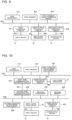
- FIG. 3 is a block diagram illustrating a first example of the hardware configuration of the heat pump system according to Embodiment 1.
- the heat pump system 1 does not include the remote control 20.
- the communication device 11 and the controller 13 of the heat pump system 1 include a first processor 41A, a first memory 42A, a first communication interface circuit 43A, an input interface circuit 44, and a first output interface circuit 45A, which are connected by a first bus 40A.
- the input device 12 corresponds to, for example, buttons or a touch panel, as described above.
- the input device 12 is connected to the input interface circuit 44 by a first cable 46A.
- the first cable 46A is, for example, a communication line or a signal line.
- the first processor 41A is, for example, a central processing unit (CPU) or a micro processing unit (MPU).
- the first memory 42A is, for example, a read only memory (ROM) or a random access memory (RAM).
- the first communication interface circuit 43A is a wireless communication interface circuit.
- the function of the communication device 11 is fulfilled by the first communication interface circuit 43A.
- the function of the controller 13 is fulfilled by reading and execution of various kinds of information stored in the first memory 42A that are performed by the first processor 41A.
- the function of control of the heat pump apparatus 10 that is performed by the controller 13 can be fulfilled by the first processor 41A, the first memory 42A, and the first output interface circuit 45A.
- the heat pump apparatus 10 is connected to the first output interface circuit 45A by a second cable 46B.
- the second cable 46B is, for example, a control line.
- the heat pump system 1 includes an input/output interface circuit instead of the first output interface circuit 45A.
- FIG. 4 is a block diagram illustrating a second example of the hardware configuration of the heat pump system according to Embodiment 1.
- the communication device 11 is provided in the heat pump apparatus 10 and the remote control 20, and the input device 12 is provided at the remote control 20.
- components that are the same as those in Fig. 3 are denoted by the same reference sigs.
- the heat pump system 1 includes the first processor 41A, the first memory 42A, the first communication interface circuit 43A, the first output interface circuit 45A, and a first wire communication interface circuit 47A, which are connected by a first bus 40A.
- the heat pump system 1 also includes a second processor 41B, a second memory 42B, a second communication interface circuit 43B, an input interface circuit 44, and a second wire communication interface circuit 47B, which are connected by a second bus 40B.
- the second processor 41B is, for example, a CPU or an MPU.
- the second memory 42B is, for example, a ROM or a RAM.
- the second communication interface circuit 43B is a wireless communication interface circuit.
- the first wire communication interface circuit 47A and the second wire communication interface circuit 47B are interface circuits for wire communication.
- the input device 12 is connected to the input interface circuit 44 by a first cable 46A.
- the heat pump apparatus 10 is connected to the first output interface circuit 45A by a second cable 46B.
- the first wire communication interface circuit 47A and the second wire communication interface circuit 47B are connected by a third cable 46C.
- the third cable 46C is, for example, a communication line.
- the function of the first communication device 11A is fulfilled by the first communication interface circuit 43A.
- the function of the first controller 13A is fulfilled by the first processor 41A, the first memory 42A, the first output interface circuit 45A, and the first wire communication interface circuit 47A.
- the function of the second communication device 11B is fulfilled by the second communication interface circuit 43B.
- the function of the second controller 13B is fulfilled by the second processor 41B, the second memory 42B, and the second wire communication interface circuit 47B.
- the heat pump system 1 includes an input/output interface circuit instead of the first output interface circuit 45A.
- the heat pump system 1 includes a first infrared communication interface circuit instead of the first wire communication interface circuit 47A.
- the heat pump system 1 also includes a second infrared communication interface circuit instead of the second wire communication interface circuit 47B.
- the heat pump system 1 does not include the third cable 46C.
- the first infrared communication interface circuit and the second infrared communication interface circuit are interface circuits for infrared communication.
- the communication device 11 In the case where the communication device 11 is provided at the remote control 20 only, it is not indispensable that the first communication interface circuit 43A is included in the heat pump system 1. In the case where the communication device 11 is provided in the heat pump apparatus 10 only, it is not indispensable that the second communication interface circuit 43B is included in the heat pump system 1.
- the function of the heat pump system 1 may be fulfilled by dedicated hardware.
- the function of the controller 13 may be fulfilled by a complex programmable logic device (CPLD) or a field programmable gate array (FPGA).
- CPLD complex programmable logic device
- FPGA field programmable gate array
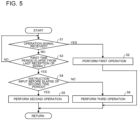
- Fig. 5 is a flowchart illustrating a control process on the heat pump apparatus that is executed by the controller of Embodiment 1.
- the controller 13 determines whether or not the communication device 11receives an operation signal from the server 3.
- the controller 13 causes the heat pump apparatus 10 to perform the first operation based on the operation signal.
- step S3 the controller 13 determines whether or not the first time period elapses from the time at which the communication device 11 last receives a signal such as an operation signal from the server 3. When determining that the first time period does not elapse (No in step S3), the controller 13 returns the process to be executed to step S1.
- step S4 determines whether or not an instruction is input to the input device 12 between the time at which the first time period elapses and the time at which a predetermined second time period elapses.
- step S5 the controller 13 causes the heat pump apparatus 10 to perform the second operation based on the instruction.
- step S6 the controller 13 causes the heat pump apparatus 10 to perform the third operation. After the step S2, the step S5, or the step S6, the controller 13 returns the process to be executed to step S1.
- step S5 in the case where the controller 13 repeats the processes from the step S1 onward, the controller 13 may skip the process of step S4 and execute the process of step S5. Alternatively, after step S5, the controller 13 may repeat the processes from step S1 to step S6. After step S6, the controller 13 repeats the processes from step S1 to step S6.
- the heat pump system 1 according to Embodiment 1 includes the heat pump apparatus 10, the communication device 11, the input device 12, and the controller 13.
- the heat pump apparatus 10 adjust the temperature of a substance such as water or air.
- the communication device 11 communicates with the server 3 and receives from the server 3, a signal including an operation signal regarding the operation of the heat pump apparatus 10.
- the input device 12 is configured to input an instruction to be given to the heat pump apparatus 10.
- the controller 13 causes the heat pump apparatus 10 to perform the first operation based on an operation signal from the server 3, while the communication device 11 is receiving a signal from the server 3.
- the controller 13 causes as a control, the heat pump apparatus 10 to perform the second operation based on an instruction input to the input device 12. Therefore, when the communication is lost, the controller 13 can cause the heat pump apparatus 10 to perform the second operation based on the instruction input to the input device 12. Thus, even when the communication is lost, the heat pump system 1 can reduce the likelihood that the heat pump apparatus 10 will be stopped, and can also cause the heat pump apparatus 10 to perform a desired operation for the user.
- the controller 13 of Embodiment 1 causes as a control, the heat pump apparatus 10 to perform the first operation based on the operation signal from the server 3. Therefore, the heat pump system 1 can optimize the operation of the heat pump apparatus 10 in the cases other than the case where the communication is lost.
- the controller 13 of Embodiment 1 performs the following process.
- the controller 13 causes the heat pump apparatus 10 to perform the third operation based on an operation schedule indicated by an operation signal received from the server 3 on or before the previous day. This can reduce the likelihood that the heat pump apparatus 10 will stop its operation and will also perform its operation based on a default value.
- the operation of the heat pump apparatus 10 based on the default value may be unsuitable for at least any of the user's usage state of the heat pump apparatus 10, the operating state of the heat pump apparatus 10, the weather condition, etc.
- the operation schedule for the previous day or the same day of the previous week may be suitable for the user's usage state of the heat pump apparatus 10, the operating state of the heat pump apparatus 10, the weather condition, etc. Therefore, by causing the heat pump apparatus 10 to perform the third operation, it is possible to reduce the likelihood that the user's comfort will be reduced when the communication is lost.
- a heat pump system 5 according to Embodiment 2 will be described.
- components that are the same as those in Embodiment 1 will be denoted by the same reference signs.
- descriptions concerning configurations and functions that are the same as those in Embodiment 1 will be omitted, unless the circumstances are exceptional.
- Fig. 6 is a block diagram illustrating a configuration example of a heat pump system and a control system according to Embodiment 2.
- a control system 200 according to Embodiment 2 includes the heat pump system 5 instead of the heat pump system 1.
- the heat pump system 5 according to Embodiment 2 includes a notification device 14 in addition to the components of the heat pump system 1 according to Embodiment 1.
- the notification device 14 may be a display device including, for example, a liquid crystal display (LCD) or a cathode ray tube (CRT) or an illuminating device including, for example, a light emitting diode (LED).
- LCD liquid crystal display
- CRT cathode ray tube
- LED light emitting diode
- the controller 13 causes as a control, the notification device 14 to make a notification that the heat pump apparatus 10 can be controlled using the input device 12.
- the notification device 14 is a display device
- the controller 13 causes the notification device 14 to display, on a screen thereof, information indicating that the heat pump apparatus 10 can be controlled using the input device 12.
- the controller 13 causes the notification device 14 to light or blink.
- the controller 13 may cause the notification device 14 to make a notification that communication between the communication device 11 and the server 3 is lost.
- the controller 13 may cause the notification device 14 to make a notification that communication between the communication device 11 and the server 3 is lost.
- Fig. 7 is a block diagram illustrating a configuration example of the heat pump system according to Embodiment 2 in the case where the heat pump system includes a remote control.
- a remote control 21 and the heat pump apparatus 10 includes respective communication devices 11, and the input device 12 is provided at the remote control 21.
- the notification device 14 is also provided at the remote control 21.
- the heat pump apparatus 10 may include the notification device 14 instead of the remote control 21 or the heat pump apparatus 10 and the remote control 21 may include respective notification devices 14.
- the kind of the notification device 14 of the remote control 21 may be the same as or different from that of the notification device 14 of the heat pump apparatus 10.
- the notification device 14 provided at the remote control 21 may be a display device, and the notification device 14 provided at the heat pump apparatus 10 may be an illuminating device.
- both the notification device 14 of the remote control 21 and the notification device 14 of the heat pump apparatus 10 may be illuminating devices.
- Fig. 8 illustrates an example of a notification made by the notification device of Embodiment 2.
- the heat pump apparatus 10 is an air-conditioning apparatus.
- the notification device 14 and the input device 12 are formed integral with each other.
- the "Meeting Room 1A" indicated in Fig. 8 is information indicating the location where the air-conditioning apparatus is installed; the "2:30 PM Friday” is information indicating the current date and time; the “Cooling” is information indicating the current operating mode of the heat pump apparatus 10 and also indicating that the heat pump apparatus 10 is in cooling operation.
- the "Indoor 28.5 degrees C” indicates that the temperature in meeting room 1A that is an air-conditioning target space is 28.5 degrees C.
- the "Set temperature 27.5 degrees C” indicates that the set temperature of the air-conditioning apparatus is 27.5 degrees C.
- the "Auto” indicates that an air-sending volume is automatically set.
- An area enclosed by a circle and including the characters "On” and “Off” corresponds to an operation start/stop button.
- the user can start the heat pump apparatus 10 by pressing the operation start/stop button when the heat pump apparatus 10 is in its stopped state.
- the user can stop the heat pump apparatus 10 by pressing the operation start/stop button when the heat pump apparatus 10 is in operation.
- areas enclosed by respective circles and including the characters "Menu,” “Back,” and “Confirm” correspond to buttons for user operations.
- the communication device 11 does not receive a signal from the server 3 for the first time period or longer, the user can cause the heat pump apparatus 10 to perform a desired operation by pressing buttons.
- the information "Remote Control Enabled” in Fig. 8 is displayed when the communication device 11 does not receive a signal from the server 3 for the first time period or longer, and is not displayed while communication between communication device 11 and the server 3 is established. In such a manner, since the information "Remote Control Enabled” is displayed on the screen while the communication is lost, the user can know that the heat pump apparatus becomes able to be operated using the remote control 21.
- Fig. 9 is a block diagram illustrating a first example of a hardware configuration of the heat pump system according to Embodiment 2.
- the hardware configuration of the heat pump system 5 as illustrated in Fig. 9 is a hardware configuration in which the heat pump system 5 does not include the remote control 21.
- the heat pump system 5 according to Embodiment 2 includes a second output interface circuit 45B connected to a first bus 40A, in addition to the components as illustrated in Fig. 3 .
- the notification device 14 is connected to the second output interface circuit 45B by a fourth cable 46D.
- the fourth cable 46D is, for example, a control line.
- Fig. 10 is a block diagram illustrating a second example of the hardware configuration of the heat pump system according to Embodiment 2.
- the hardware configuration of the heat pump system 5 as illustrated in Fig. 10 is a hardware configuration in which the heat pump system 5 includes the remote control 21.
- Fig. 10 illustrates the hardware configuration of the heat pump system 5 in the case where the notification device 14 is provided at the remote control 21.
- the heat pump system 5 according to Embodiment 2 includes a third output interface circuit 45C connected to a second bus 40B, in addition to the components as illustrated in Fig. 4 .
- the notification device 14 is connected to the third output interface circuit 45C by a fifth cable 46E.
- the fifth cable 46E is, for example, a control line.
- the heat pump system 5 includes the second output interface circuit 45B as illustrated in Fig. 9 in addition to the components as illustrated in Fig. 10 .
- the second output interface circuit 45B is connected to the first bus 40A.
- the notification device 14 is connected to the second output interface circuit 45B by the fourth cable 46D.
- the third output interface circuit 45C, the fifth cable 46E, and the notification device 14, which can be connected to the third output interface circuit 45C by the fifth cable 46E, are not provided.
- Fig. 11 is a flowchart illustrating a control process for the heat pump apparatus and the notification device that is executed by the controller of Embodiment 2.
- the process of step S11 is the same as step S1.
- step S11 when the communication device 11 receives an operation signal (Yes in step S11), in step S12, the controller 13 determines whether or not the notification device 14 is in a notification state.
- the notification state means a state in which the notification device 14 makes a notification that the heat pump apparatus 10 can be controlled using the input device 12 or a notification that the communication between the communication device 11 and the server 3 is lost.
- the controller 13 causes the process to be executed to proceed to step S14.
- step S13 the controller 13 causes as a control, the notification device 14 to be in a non-notification state.
- the non-notification state means a state in which the notification device 14 does not make a notification that the heat pump apparatus 10 can be controlled using the input device 12 or a notification that the communication between the communication device 11 and the server 3 is lost. It should be noted that the non-notification state may be a state in which the notification device 14 makes a notification that the heat pump apparatus 10 cannot be controlled using the input device 12.
- step S13 the controller 13 causes the process to be executed to proceed to step S14.
- the process of step S14 is the same as the process of step S2.
- the controller 13 may execute the process of step S12 or the processes of steps S12 to S13, in parallel with the process of step S14.
- step S12 when the notification device 14 is in the non-notification state, the controller 13 returns the process to step S11 after step S14.
- step S12 when the notification device 14 is in the notification state, the controller 13 returns the process to step S11 after steps S13 and S14.
- the controller 13 may execute the process of step S12 or the processes of steps S12 and S13 after step S14.
- step S12 when the notification device 14 is in the non-notification state, the controller 13 returns the process to step S11.
- step S12 when the notification device 14 is in the notification state, the controller 13 returns the process to step S11 after step S13.
- step S11 when the communication device 11 does not receive an operation signal (No in step S11), the controller 13 causes the process to proceed to step S15.
- the process of step S15 is the same as the process of step S3.
- step S15 when not determining that the first time period elapses (No in step S15), the controller 13 returns the process to step S11.
- step S16 when determining that the first time period elapses (Yes in step S15), in step S16, the controller 13 determines whether the notification device 14 is in the notification state or not. When determining that the notification device 14 is in the notification state (Yes in step S16), the controller 13 causes the process to proceed to step S18.
- step S17 the controller 13 causes as a control, the notification device 14 to be in the notification state.
- step S17 the controller 13 causes the process to proceed to step S18.
- steps S18 to S20 are the same as the processes of steps S4 to S6.
- step S14, S19, or S20 the controller 13 returns the process to step S11.
- step S19 in the case of repeating the processes from the process of step S11 onward, the controller 13 may skip the process of step S18 and execute the process of step S19. Alternatively, after step S19, the controller 13 may repeat the processes from step S11 to step S20. After step S20, the controller 13 repeats the operations from step S11 to step S20.
- the heat pump system 5 according to Embodiment 2 further includes the notification device 14.
- the notification device 14 makes a notification that the heat pump apparatus 10 can be controlled using the input device 12. It should be noted that in some cases, the user dos not notice that the communication between the communication device 11 and the server 3 is lost. As a result, the heat pump apparatus 10 may perform an undesired operation for the user or an operation that does not match the actual condition such as the operating state or the weather condition.
- the notification device 14 makes a notification that the heat pump apparatus 10 can be controlled using the input device 12, thereby prompting the user to input an instruction to the input device 12.
- the user can promptly notice the necessity of inputting an instruction to the input device 12.
- the user promptly inputs an instruction to the input device 12 it is possible to reduce the likelihood that the heat pump apparatus 10 will operate in a manner that does not match the actual condition, and is therefore possible to ensure the comfort for the user.
- the heat pump system 5 according to Embodiment 2 includes the notification device 14 in addition to the components included in the heat pump system 1 according to Embodiment 1.
- the notification device 14 makes a notification that communication between the communication device 11 and the server 3 is not established.
- the user can recognize that the operation of the heat pump apparatus 10 is not optimized.
- the user can recognize that the heat pump apparatus 10 may perform an operation that does not match the actual condition such as the operating condition or the weather condition.
- the user can promptly recognize the necessary of inputting an instruction to the input device 12.
- the user promptly input an instruction to the input device 12 it is possible to reduce the likelihood that the heat pump apparatus 10 will operate in a manner that does not match the actual condition, and is therefore possible to ensure the comfort for the user.
- the heat pump system 5 according to Embodiment 2 further includes the notification device 14. While the communication device 11 is receiving a signal from the server 3, the notification device 14 makes a notification that the heat pump apparatus 10 cannot be controlled using the input device 12. As a result, while the communication between the server 3 and the communication device 11 is established, the user can recognize that the heat pump apparatus 10 performs an optimized first operation. Therefore, the heat pump system 5 can reduce the likelihood that the user will input an unnecessary instruction to the input device 12. It is therefore possible to reduce the processing of the controller 13 that would be executed if the instruction is input to the input device 12.
- the notification device 14 provides information regarding inputting of an instruction to the input device 12 when the communication device 11 does not receive a signal from the server 3 for the first time period or longer.
- the heat pump system 5 according to Embodiment 3 will be described in detail. It should be noted that regarding Embodiment 3, components that are the same as those in Embodiments 1 and 2 will be denoted by the same reference signs. In addition, regarding Embodiment 3, descriptions concerning configurations and functions that are same as those in Embodiments 1 and 2 will be omitted, unless the circumstances are exceptional.
- a configuration example of a control system 200 according to Embodiment 3 is illustrated in Fig. 6 as in Embodiment 2.
- the heat pump system 5 according to Embodiment 3 may include the remote control 21 as in Embodiment 2, and in this case, a configuration example of the heat pump system 5 is illustrated in Fig. 7 .
- a hardware configuration of the heat pump system 5 according to Embodiment 3 is illustrated in Figs. 9 and 10 as in Embodiment 2.
- the heat pump apparatus 10 In the environment that the heat pump apparatus 10 operates based on an operation signal from the server 3 for optimization of the operation of the heat pump apparatus 10, when the user tries to control the heat pump apparatus 10 using the input device 12 while the communication is lost, the user may not know what instruction should be input to the input device 12.
- the heat pump apparatus 10 is a water heater.
- the water heater in some cases, the amount of supplied hot water is less than the amount of consumed hot water per unit time. For this reason, the water heater may be provided with a tank for storage of hot water, and store hot water in the tank before consumption of hot water. Furthermore, the water heater also performs an operation to heat hot water in the tank or an operation to maintain the temperature of hot water in the tank.
- the server 3 While communication between the server 3 and the communication device 11 in the water heater is established, the server 3 transmits an operation signal indicating a target storage amount of hot water and a target temperature to the water heater.
- the water heater adjusts the storage amount of hot water in the tank and the temperature of the hot water in the tank based on an operation signal.
- the heat pump system 5 cannot obtain from the server 3, an operation signal indicating the target storage amount of the hot water and the target temperature.
- the user when inputting an instruction to the water heater, in many cases, the user does not know that the target storage amount of the hot water and the target temperature are necessary. Also, in many cases, the user does not know those values of the target storage amount of the hot water and the target temperature that are necessary for the comfort for the user.
- the notification device 14 in Embodiment 3 is the above display device.
- the notification device 14 is caused by the control by the controller 13 to display on the screen, guidance information regarding inputting of an instruction to the input device 12, such as the above target storage amount of hot water and the target temperature.
- the guidance information may include, for example, content that prompts the user to input the target storage amount of hot water and the target temperature.
- the guidance information may include specific values of the target storage amount of hot water and the target temperature.
- Fig. 12 is a flowchart illustrating a control process of the heat pump apparatus and the notification device that is executed by the controller of Embodiment 3.
- the process of step S31 is the same as step S1.
- step S31 when the communication device 11 receives an operation signal (Yes in step S31), in step S32, the controller 13 determines whether the notification device 14 is in a guidance state or not.
- the guidance state is a state in which the notification device 14 displays guidance information on the screen.
- the controller 13 causes the process to proceed to step S34.
- step S33 the controller 13 causes as a control, the notification device 14 to be in a non-guidance state.
- the non-guidance state is a state in which the notification device 14 does not display guidance information on the screen.
- step S34 the controller 13 causes the process to proceed to step S34.
- the process of step S34 is the same as the process of step S2.
- the controller 13 may execute the process of step S32 or the processes of steps S32 to S33, in parallel with the process of step S34. In this case, in step S32, when the notification device 14 is in the guidance state, the controller 13 returns the process to step S31, after step S34. In step S32, when the notification device 14 is in the guidance state, the controller 13 returns the process to step S31 after steps S33 and S34.
- the controller 13 may execute the process of step S32 or the processes of steps S32 and S33, after step S34.
- step S32 when the notification device 14 is not in the guidance state, the controller 13 returns the process to step S31.
- step 32 when the notification device 14 is in the guidance state, the controller 13 returns the process to step S31, after step S33.
- step S31 when the communication device 11 does not receive an operation signal (No in step S31), the controller 13 causes the process to proceed to step S35.
- the process of step S35 is the same as the process of step S3.
- step S35 when determining that the first time period does not elapse (No in step S35), the controller 13 returns the process to step S31.
- step S35 when determining that the first time period elapses (Yes in step S35), in step S36, the controller 13 determines whether the notification device 14 is in the guidance state or not. When the notification device 14 is in the guidance state (Yes in step S36), the controller 13 causes the process to proceed to step S38.
- step S37 the controller 13 causes as a control, the notification device 14 to be in the guidance state.
- step S38 the controller 13 causes the process to proceed to step S38.
- steps S38 to S40 are the same as the processes of steps S4 to S6.
- step S34, S39, or S40 the controller 13 returns the process to step S31.
- step S39 in the case of repeating the processes from step S31 onward, the controller 13 may skip the process of step S38 and execute the process of step S39. Alternatively, after step S39, the controller 13 may repeat the processes of step S31 to step S40. After step S40, the controller 13 repeats the processes of step S31 to step S40.
- the heat pump system 5 according to Embodiment 3 further includes the notification device 14.
- the notification device 14 provides as a notification, guidance information regarding inputting of an instruction to the input device 12.
- the user can input to the input device 12, information that needs to be input to the input device 12 for the operation of the heat pump apparatus 10. Therefore, when the communication is lost, the heat pump system 5 can reduce the likelihood that the heat pump apparatus 10 will stop its operation.
- the heat pump system 5 can also assist the user such that the heat pump apparatus 10 can perform a desired operation for the user. Even when the communication is lost, the user can input an instruction to the input device 12 based on the guidance information, thereby causing the heat pump apparatus 10 to maintain the comfort for the user.
- the heat pump apparatus 10 is a heat pump water heater, and the above substance is hot water.
- the water heater includes a tank for storing hot water.
- the guidance information includes information regarding both or one of the target amount of hot water to be stored in the tank and the target temperature of hot water in the tank.
- the heat pump system 5 can assist the user in inputting an instruction to the input device 12. Therefore, when the user inputs an instruction to the input device 12 based on the guidance information, the heat pump apparatus 10 can maintain the comfort for the user without stopping its operation.
- the controller 13 of Embodiment 3 may cause as a control, the notification device 14 to display condition information indicating the operating state of the heat pump apparatus 10, and the notification device 14 may display the condition information.
- the condition information corresponds to the above condition signal.
- the second controller 13B may obtain from the first controller 13A, a control signal that the first controller 13A outputs to the heat pump apparatus 10.
- the notification device 14 displays the operating condition of the heat pump apparatus 10 that is an operation condition indicated by the control signal.
- the second controller 13B may also obtain detection results from the various sensors through the first controller 13A.
- the notification device 14 displays that operating condition of the heat pump apparatus 10 that is an operating condition based on detection results from the various sensors. Thus, the user can recognize the operating condition of the heat pump apparatus 10 through the notification device 14.
- a control system 300 according to Embodiment 4 enables the user to easily recognize the operating condition of the heat pump apparatus 10.
- the control system 300 according to Embodiment 4 will be described in detail. It should be noted that regarding Embodiment 4, components that are the same as those in any of Embodiments 1 to 3 will be denoted by the same reference signs. Regarding Embodiment 4, descriptions concerning configurations and functions that are the same as those in any of Embodiments 1 to 3 will be omitted, unless the circumstances are exceptional.
- Fig. 13 illustrates a configuration example of the control system according to Embodiment 4.
- the control system 300 according to Embodiment 4 includes a server 6 instead of the server 3 in the control system 100 of Embodiment 1 or the control system 200 of Embodiments 2 and 3.
- the server 6 wirelessly communicates with a terminal device 7 of the user.
- the server 6 may also perform wire communication with the terminal device 7.
- the terminal device 7 is, for example, a communication terminal device, such as a smartphone, a personal computer (PC), or a tablet terminal.
- the server 6 transmits to the terminal device 7, a condition signal received from the communication device 11.
- the user can recognize the operating condition of the heat pump apparatus 10 by checking condition information displayed on a screen of the terminal device 7.
- control system 300 does not include the notification device 14 that is a display device
- the user can know the operating condition of the heat pump apparatus 10, through the terminal device 7.
- the control system 300 includes the notification device 14 that is a display device
- the user can easily know the operating condition of the heat pump apparatus 10 without moving to a location where the heat pump apparatus 10 or the remote control 21 provided with the notification device 14 is installed.
Landscapes
- Engineering & Computer Science (AREA)
- Chemical & Material Sciences (AREA)
- Combustion & Propulsion (AREA)
- Mechanical Engineering (AREA)
- General Engineering & Computer Science (AREA)
- Physics & Mathematics (AREA)
- Thermal Sciences (AREA)
- Computer Hardware Design (AREA)
- Human Computer Interaction (AREA)
- Heat-Pump Type And Storage Water Heaters (AREA)
- Air Conditioning Control Device (AREA)
Abstract
Description
- The present disclosure relates to a heat pump system that operates based on a signal received via a network and a control system including the heat pump system.
- In recent years, in the field of heat pumps, a larger number of heat pumps have had the aim of optimizing the operation of a heat pump apparatus. In order to optimize the operation of heat pump apparatus, it is necessary to obtain data indicating at least any of the capability of the heat pump apparatus, the type of the heat pump apparatus, a weather condition at the location where the heat pump apparatus is installed, the operation schedule of the heat pump apparatus, etc. However, the amount of such data can be huge as the amount of data to be processed by a controller, such as a remote control provided at the heat pump apparatus. Therefore, in most cases, a remotely installed server determines an optimal operation of the heat pump apparatus based on the data. The server then transmits information regarding the determined optimal operation to a heat pump system through Internet connection and causes the heat pump apparatus to perform the optimal operation (see, for example, Patent Literature 1).
- Patent Literature 1: International Publication No.
2020/059473 - In the above system in which the server manages the operation of the heat pump apparatus, it may be set that the user is not allowed to operate the heat pump apparatus, in order to prevent the user from interfering with an operation management by the server. In such a case, for example, if communication is lost due to a disaster such as a typhoon, the heat pump apparatus fails to receive a signal from the server, and as a result, may unable to operate, or perform an undesired operation for the user.
- The present disclosure is applied to solve the above problem, and relates to a heat pump system and a control system that enable a heat pump apparatus to perform a desired operation for the user when communication with a server is lost.
- A heat pump system according to an embodiment of the present disclosure includes: a heat pump apparatus configured to adjust a temperature of a substance; a communication device configured to communicate with a server to receive from the server, a signal including an operation signal regarding an operation of the heat pump apparatus; an input device configured to input an instruction for the heat pump apparatus; and a controller configured to causes the heat pump apparatus to perform a first operation based on the operation signal while the communication device is receiving the signal. The controller is configured to cause, when the communication device does not receive the signal for a predetermined first time period or longer, the heat pump apparatus to perform a second operation based on the instruction input to the input device.
- A control system according to another embodiment of the present disclosure includes: a server; a heat pump apparatus configured to adjust a temperature of a substance; a communication device configured to communicate with the server to receive from the server, a signal including an operation signal regarding an operation of the heat pump apparatus; an input device configured to input an instruction for the heat pump apparatus; and a controller configured to causes as a control, the heat pump apparatus to perform a first operation based on the operation signal while the communication device is receiving the signal. The controller is configured to cause as a control, when the communication device does not receive the signal for predetermined first time period or longer, the heat pump apparatus to perform a second operation based on the instruction input to the input device.
- In the heat pump system and the control system according to the embodiments of the present disclosure, when the communication device does not receive a signal from the server for the first time period, the controller causes the heat pump apparatus to perform the second operation based on an instruction input to the input device. Thus, the heat pump apparatus can operate even when communication is lost. Furthermore, a user can cause the heat pump apparatus to perform a desired operation by inputting an instruction to the input device.
-
- [
Fig. 1] Fig. 1 is a block diagram illustrating a configuration example of a control system and a heat pump system according toEmbodiment 1. - [
Fig. 2] Fig. 2 is a block diagram illustrating a configuration example of the heat pump system according toEmbodiment 1 in the case where the heat pump system includes a remote control. - [
Fig. 3] Fig. 3 is a block diagram illustrating a first example of the hardware configuration of the heat pump system according toEmbodiment 1. - [
Fig. 4] Fig. 4 is a block diagram illustrating a second example of the hardware configuration of the heat pump system according toEmbodiment 1. - [
Fig. 5] Fig. 5 is a flowchart illustrating a control process for a heat pump apparatus that is executed by a controller ofEmbodiment 1. - [
Fig. 6] Fig. 6 is a block diagram illustrating a configuration example of a heat pump system and a control system according to Embodiment 2. - [
Fig. 7] Fig. 7 is a block diagram illustrating a configuration example of the heat pump system according to Embodiment 2 in the case where the heat pump system includes a remote control. - [
Fig. 8] Fig. 8 illustrates an example of a notification made by a notification device of Embodiment 2. - [
Fig. 9] Fig. 9 is a block diagram illustrating a first example of the hardware configuration of the heat pump system according to Embodiment 2. - [
Fig. 10] Fig. 10 is a block diagram illustrating a second example of the hardware configuration of the heat pump system according to Embodiment 2. - [
Fig. 11] Fig. 11 is a flowchart illustrating a control process for a heat pump apparatus and the notification device that is executed by a controller of Embodiment 2. - [
Fig. 12] Fig. 12 is a flowchart illustrating a control process for a heat pump apparatus and a notification device that is executed by a controller ofEmbodiment 3. - [
Fig. 13] Fig. 13 illustrates a configuration example of a control system according toEmbodiment 4. - Hereinafter, heat pump systems and control systems according to embodiments will be described in detail with reference to the drawings.
-
Fig. 1 is a block diagram illustrating a configuration example of a control system and a heat pump system according toEmbodiment 1. Acontrol system 100 includes aheat pump system 1 and aserver 3. Theserver 3 is, for example, a cloud server, and wirelessly communicates with theheat pump system 1. - The
heat pump system 1 includes aheat pump apparatus 10, acommunication device 11, aninput device 12, and acontroller 13. Thecommunication device 11 and thecontroller 13 may be provided in a housing that forms an outer portion of theheat pump apparatus 10 or outside the housing. Theinput device 12 may be provided on a surface of the housing of theheat pump apparatus 10 or may be provided separate from theheat pump apparatus 10. - The
heat pump apparatus 10 is a heat pump-type apparatus that adjusts the temperature of a substance such as water or air. Theheat pump apparatus 10 is, for example, a water heater, air-conditioning apparatus, a freezer, or a refrigerator. Thecommunication device 11 wirelessly communicates with theserver 3 and receives a signal from theserver 3. As the signal, various kinds of signals are present. One of the signals is an operation signal regarding the operation of theheat pump apparatus 10. Thecommunication device 11 periodically receives the operation signal from theserver 3. - The operation signal is a signal that indicates an operation content of the
heat pump apparatus 10. The operation content may correspond to an operation schedule. For example, in the case where theheat pump apparatus 10 is a water heater, as the operation content, a target storage amount of hot water and a target temperature are present. The target storage amount of hot water means the target amount of hot water to be stored in a tank of the water heater. The target temperature means the target temperature of hot water stored in the tank. - The signals that are transmitted from the
server 3 to thecommunication device 11 include a condition request signal in addition to the operation signal. The condition request signal is a signal that requests information indicating the current operating condition of theheat pump apparatus 10. In the case where theheat pump apparatus 10 is a water heater, the information indicating the current operating condition of theheat pump apparatus 10 corresponds to the current amount of hot water stored in the tank and the current temperature of the hot water in the tank. - The various kinds of signals that are transmitted from the
server 3 to thecommunication device 11 may include a response request signal that requests a response from theheat pump system 1 and that is transmitted as a request from theserver 3. The response request signal is intended to confirm whether or not communication of theserver 3 with theheat pump system 1 is established. - The
input device 12 corresponds to, for example, buttons or a touch panel that enables a user to input an instruction to theheat pump apparatus 10. - The
controller 13 causes theheat pump apparatus 10 to perform a first operation based on an operation signal that thecommunication device 11 receives from theserver 3. While thecommunication device 11 is receiving a signal from theserver 3, that is, while communication between thecommunication device 11 and theserver 3 is established, thecontroller 13 causes theheat pump apparatus 10 to perform the first operation, even when the user inputs an instruction to theinput device 12. - It should be noted that in order to optimize the operation of the
heat pump apparatus 10, it is necessary to provide information indicating at least any of a weather condition at the location where theheat pump apparatus 10 is installed, the model of theheat pump apparatus 10, the capability of theheat pump apparatus 10, a desired temperature of the substance for the user, and a desired operation schedule of theheat pump apparatus 10 for the user. In the following, information necessary for optimization of the operation of theheat pump apparatus 10 may be referred to as optimization information. In some cases, the optimization information is a huge amount of data for processing by theheat pump system 1. Therefore, instead of theheat pump system 1, theserver 3 produces an operation signal regarding the operation of theheat pump apparatus 10 based on the optimization information. Theheat pump apparatus 10 operates in response to the operation signal, whereby the operation of theheat pump apparatus 10 is optimized. By contrast, the instruction input to theinput device 12 do not necessarily optimize the operation of theheat pump apparatus 10. In addition, in some cases, the contents of the instruction do not necessarily conform to content indicated by the operation signal. While communication between thecommunication device 11 and theserver 3 is established, even when an instruction is input to theinput device 12, thecontroller 13 causes theheat pump apparatus 10 to perform the first operation based on the operation signal, in order to prevent optimization of the operation of theheat pump apparatus 10 from being hindered by the instruction input by theinput device 12. - Communication between the
heat pump system 1 and theserver 3 may be lost when a disaster such as a typhoon occurs. If the communication is lost for a long time period, the operation of theheat pump apparatus 10 may be stopped for a long time period or theheat pump apparatus 10 may perform, based on, for example, a default value, an undesired operation for the user, or an operation that does not match an actual condition. The operation that is based on the default value and does not match the actual condition means an operation that can cause shortage of hot water in the case where theheat pump apparatus 10 is a water heater. In order to avoid such a situation, theheat pump system 1 according toEmbodiment 1 has the following functions. - When the
communication device 11 does not receive a signal from theserver 3 for a predetermined first time period or longer, thecontroller 13 ofEmbodiment 1 causes theheat pump apparatus 10 to perform a second operation based on an instruction input to theinput device 12. It is therefore possible to reduce the likelihood that when the communication is lost, the operation of theheat pump apparatus 10 will be stopped or theheat pump apparatus 10 will perform an undesired operation. The undesired operation is, for example, an operation that is based on the default value and that is not desired by the user or an operation that does not match the actual condition. - When no signal is received from the
server 3 and no instruction is input to theinput device 12 for the first time period or longer, thecontroller 13 ofEmbodiment 1 causes theheat pump apparatus 10 to perform a third operation. The third operation is an operation based on an operation schedule for a specific date, such as the previous day or the same day of the last week. The operation schedule for the specific date is information corresponding to an operation signal that is received by thecommunication device 11 from theserver 3 prior to the specific date. In this case, thecontroller 13 temporarily stores the information corresponding to the operation signal that is received by thecommunication device 11 from theserver 3. For example, thecontroller 13 stores information corresponding to an operation signal for a specific period such as a week or a month. - When the
communication device 11 receives a condition request signal from theserver 3, thecontroller 13 causes as a control, thecommunication device 11 to transmit to theserver 3, a condition signal that indicates the operating condition of theheat pump apparatus 10. The information indicated by the condition signal includes information corresponding to a control signal that thecontroller 13 outputs to theheat pump apparatus 10. In the case where theheat pump apparatus 10 includes various sensors, thecontroller 13 obtains detection results from the various sensors, and the information indicated by the condition signal includes the detection results from the various sensors. When thecommunication device 11 receives a response request signal from theserver 3, thecontroller 13 causes as a control, thecommunication device 11 to transmit a response signal to theserver 3. - The
heat pump system 1 according toEmbodiment 1 may include aremote control 20 for use in remote control of theheat pump apparatus 10 by the user.Fig. 2 is a block diagram illustrating a configuration example of the heat pump system according toEmbodiment 1 in the case where the heat pump system includes a remote control. In the case where theheat pump apparatus 10 or being provided in contact with the housing. Theinput device 12 may be provided on the surface of the housing that forms the outer portion of theheat pump apparatus 10 or may be provided at theremote control 20. The followingdescription concerning Embodiment 1 is made by referring to by way of example the case where theheat pump apparatus 10 and theremote control 20 includerespective communication devices 11, and theremote control 20 also includes theinput device 12. Also, in the following description, thecommunication device 11 provided in theheat pump apparatus 10 may be referred to as afirst communication device 11A, and thecommunication device 11 provided in theremote control 20 may be referred to as asecond communication device 11B. - The
first controller 13A and thesecond controller 13B perform wire communication with each other. It should be noted that hefirst controller 13A and thesecond controller 13B may wirelessly communicate with each other through infrared communication. Even when an instruction is input to theinput device 12 while communication between thesecond communication device 11B and theserver 3 is established, thesecond controller 13B does not transmit the instruction to thefirst controller 13A. Thefirst controller 13A causes theheat pump apparatus 10 to perform the first operation based on an operation signal received by thefirst communication device 11A. When thesecond communication device 11B does not receive a signal for the first time period or longer, thesecond controller 13B transmits to thefirst controller 13A, the instruction input to theinput device 12, and thefirst controller 13A causes theheat pump apparatus 10 to perform the second operation based on the instruction. - Even when communication between the
second communication device 11B and theserver 3 is established, thesecond controller 13B may transmit the instruction input to theinput device 12 to thefirst controller 13A. In this case, while communication between thefirst communication device 11A and theserver 3 is established, thefirst controller 13A causes theheat pump apparatus 10 to perform the first operation based on the operation signal received by thefirst communication device 11A, not the second operation based on the instruction obtained from thesecond controller 13B. When thefirst communication device 11A does not receive a signal from theserver 3 for the first time period or longer, thefirst controller 13A causes theheat pump apparatus 10 to perform the second operation based on the instruction input to theinput device 12 and obtained from thesecond controller 13B. - When both or one of the
first communication devices 11A and thesecond communication device 11B receives a response request signal from theserver 3, thefirst controller 13A causes, as a control, thefirst communication device 11A to transmit a response signal to theserver 3. When thefirst communication device 11A does not receive a response request signal, but thesecond communication device 11B receives a response request signal, thefirst controller 13A obtains the response request signal via thesecond controller 13B. When both or one of thefirst communication devices 11A and thesecond communication device 11B receives a response request signal from theserver 3, thesecond controller 13B may cause, as a control, thesecond communication device 11B to transmit a response signal to theserver 3. In this case, when thesecond communication device 11B does not receive a response request signal, and thefirst communication device 11A receives a response request signal, thesecond controller 13B obtains the response request signal via thefirst controller 13A. - When both or one of the
first communication devices 11A and thesecond communication device 11B receives a condition request signal from theserver 3, thefirst controller 13A causes, as a control, thefirst communication device 11A to transmit a condition signal to theserver 3. When thefirst communication device 11A does not receive a condition request signal, but thesecond communication device 11B receives a condition request signal, thefirst controller 13A obtains the condition request signal via thesecond controller 13B. - When both or one of the
first communication devices 11A and thesecond communication device 11B receives an information request signal from theserver 3, thesecond controller 13B may causes, as a control, thesecond communication device 11B to transmit a condition signal to theserver 3. In this case, when thesecond communication device 11B does not receive a response request signal, but thefirst communication device 11A receives a response request signal, thesecond controller 13B obtains the response request signal via thefirst controller 13A. When thesecond controller 13B causes, as a control, thesecond communication device 11B to transmit a condition signal to theserver 3, thesecond controller 13B may obtain, from thefirst controller 13A, information corresponding to a control signal for controlling theheat pump apparatus 10. Furthermore, thesecond controller 13B may also obtain detection results from the various sensors provided at theheat pump apparatus 10, through thefirst controller 13A. - When neither the
first communication device 11A nor thesecond communication device 11B receives an operation signal, and no instruction is input to theinput device 12, thefirst controller 13A does not receive an operation signal or an instruction from thesecond controller 13B. Furthermore, thefirst controller 13A does not obtain an operation signal from thefirst communication device 11A. In this case, thefirst controller 13A causes theheat pump apparatus 10 to perform the third operation. - In the case where the
communication device 11 is provided at theremote control 20 only, thefirst communication device 11A as illustrated inFig. 2 is not provided. In this case, while communication between thesecond communication device 11B and theserver 3 is established, thesecond controller 13B transmits to thefirst controller 13A, an operation signal received by thesecond communication device 11B. Then, thefirst controller 13A causes theheat pump apparatus 10 to perform the first operation based on the operation signal obtained from thesecond controller 13B. While communication between thesecond communication device 11B and theserver 3 is established, thesecond controller 13B may or may not transmit an instruction input to theinput device 12 to thefirst controller 13A. When thesecond communication device 11B does not receive a signal from theserver 3 for the first time period or longer, thesecond controller 13B transmits to thefirst controller 13A, the instruction input to theinput device 12. When thefirst controller 13A does not receive an operation signal from thesecond controller 13B for the first time period or longer, thefirst controller 13A causes theheat pump apparatus 10 to perform the second operation based on the instruction obtained from thesecond controller 13B. - In the case where the
communication device 11 is provided at theremote control 20 only, when thesecond communication device 11B receives a response request signal from theserver 3, thesecond controller 13B causes as a control, thesecond communication device 11B to transmit a response signal to theserver 3. - In the case where the
communication device 11 is provided at theremote control 20 only, when thesecond communication device 11B receives a condition request signal from theserver 3, thesecond controller 13B causes as a control, thesecond communication device 11B to transmit a condition signal to theserver 3. In this case, thesecond controller 13B may obtain, from thefirst controller 13A, information corresponding to a control signal for controlling theheat pump apparatus 10. Furthermore, thesecond controller 13B may obtain detection results from the various sensors provided at theheat pump apparatus 10, via thefirst controller 13A. - In the case where the
communication device 11 is provided at theremote control 20 only, when thesecond communication device 11B does not receive an operation signal, and no instruction is input to theinput device 12, thefirst controller 13A does not receive an operation signal or an instruction from thesecond controller 13B. In this case, thefirst controller 13A causes theheat pump apparatus 10 to perform the third operation. - In the case where the
communication device 11 is not provided at theremote control 20 but is provided in theheat pump apparatus 10 only, thesecond communication device 11B as illustrated inFig. 2 is not provided. In this case, while communication between thefirst communication device 11A and theserver 3 is established, thefirst controller 13A causes theheat pump apparatus 10 to perform the first operation based on an operation signal received by thefirst communication device 11A. When thefirst communication device 11A does not receive a signal from theserver 3 for the first time period or longer, thefirst controller 13A causes theheat pump apparatus 10 to perform the second operation based on an instruction that is input to theinput device 12 and obtained from thesecond controller 13B. - In the case where the
communication device 11 is provided in theheat pump apparatus 10 only, when thefirst communication device 11A receives a response request signal from theserver 3, thefirst controller 13A causes as a control, thefirst communication device 11A to transmit a response signal to theserver 3. Furthermore, when thefirst communication devices 11A receives a condition request signal from theserver 3, thefirst controller 13A causes as a control, thefirst communication device 11A to transmit a condition signal to theserver 3. - In the case where the
communication device 11 is provided in theheat pump apparatus 10 only, when thefirst communication device 11A does not receive an operation signal from theserver 3, and no instruction is input to theinput device 12, thefirst controller 13A does not obtain an operation signal from thefirst communication device 11A. Furthermore, thefirst controller 13A does not receive an instruction from thesecond controller 13B. In this case, thefirst controller 13A causes theheat pump apparatus 10 to perform the third operation. - A hardware configuration of the
heat pump system 1 according toEmbodiment 1 will be described.Fig. 3 is a block diagram illustrating a first example of the hardware configuration of the heat pump system according toEmbodiment 1. In the hardware configuration of theheat pump system 1 as illustrated inFig. 3 , theheat pump system 1 does not include theremote control 20. Thecommunication device 11 and thecontroller 13 of theheat pump system 1 include afirst processor 41A, afirst memory 42A, a firstcommunication interface circuit 43A, aninput interface circuit 44, and a firstoutput interface circuit 45A, which are connected by afirst bus 40A. Theinput device 12 corresponds to, for example, buttons or a touch panel, as described above. Theinput device 12 is connected to theinput interface circuit 44 by afirst cable 46A. Thefirst cable 46A is, for example, a communication line or a signal line. - The
first processor 41A is, for example, a central processing unit (CPU) or a micro processing unit (MPU). Thefirst memory 42A is, for example, a read only memory (ROM) or a random access memory (RAM). The firstcommunication interface circuit 43A is a wireless communication interface circuit. The function of thecommunication device 11 is fulfilled by the firstcommunication interface circuit 43A. The function of thecontroller 13 is fulfilled by reading and execution of various kinds of information stored in thefirst memory 42A that are performed by thefirst processor 41A. The function of control of theheat pump apparatus 10 that is performed by thecontroller 13 can be fulfilled by thefirst processor 41A, thefirst memory 42A, and the firstoutput interface circuit 45A. Theheat pump apparatus 10 is connected to the firstoutput interface circuit 45A by asecond cable 46B. Thesecond cable 46B is, for example, a control line. In the case where various sensors are provided at theheat pump apparatus 10, and thecontroller 13 obtains detection results from the various sensors, theheat pump system 1 includes an input/output interface circuit instead of the firstoutput interface circuit 45A. - Next, a hardware configuration of the
heat pump system 1 in the case where theheat pump system 1 includes theremote control 20 will be described.Fig. 4 is a block diagram illustrating a second example of the hardware configuration of the heat pump system according toEmbodiment 1. In the hardware configuration of theheat pump system 1 as illustrated inFig. 4 , thecommunication device 11 is provided in theheat pump apparatus 10 and theremote control 20, and theinput device 12 is provided at theremote control 20. InFig. 4 , components that are the same as those inFig. 3 are denoted by the same reference sigs. Theheat pump system 1 includes thefirst processor 41A, thefirst memory 42A, the firstcommunication interface circuit 43A, the firstoutput interface circuit 45A, and a first wirecommunication interface circuit 47A, which are connected by afirst bus 40A. Theheat pump system 1 also includes asecond processor 41B, asecond memory 42B, a secondcommunication interface circuit 43B, aninput interface circuit 44, and a second wirecommunication interface circuit 47B, which are connected by asecond bus 40B. - The
second processor 41B is, for example, a CPU or an MPU. Thesecond memory 42B is, for example, a ROM or a RAM. The secondcommunication interface circuit 43B is a wireless communication interface circuit. The first wirecommunication interface circuit 47A and the second wirecommunication interface circuit 47B are interface circuits for wire communication. Theinput device 12 is connected to theinput interface circuit 44 by afirst cable 46A. Theheat pump apparatus 10 is connected to the firstoutput interface circuit 45A by asecond cable 46B. The first wirecommunication interface circuit 47A and the second wirecommunication interface circuit 47B are connected by athird cable 46C. Thethird cable 46C is, for example, a communication line. - The function of the
first communication device 11A is fulfilled by the firstcommunication interface circuit 43A. The function of thefirst controller 13A is fulfilled by thefirst processor 41A, thefirst memory 42A, the firstoutput interface circuit 45A, and the first wirecommunication interface circuit 47A. The function of thesecond communication device 11B is fulfilled by the secondcommunication interface circuit 43B. The function of thesecond controller 13B is fulfilled by thesecond processor 41B, thesecond memory 42B, and the second wirecommunication interface circuit 47B. - In the case where various sensors are provided at the
heat pump apparatus 10, and thefirst controller 13A obtains detection results from the various sensors, theheat pump system 1 includes an input/output interface circuit instead of the firstoutput interface circuit 45A. - In the case where the
first controller 13A and thesecond controller 13B perform infrared communication, not wire communication, theheat pump system 1 includes a first infrared communication interface circuit instead of the first wirecommunication interface circuit 47A. Theheat pump system 1 also includes a second infrared communication interface circuit instead of the second wirecommunication interface circuit 47B. Theheat pump system 1 does not include thethird cable 46C. The first infrared communication interface circuit and the second infrared communication interface circuit are interface circuits for infrared communication. - In the case where the
communication device 11 is provided at theremote control 20 only, it is not indispensable that the firstcommunication interface circuit 43A is included in theheat pump system 1. In the case where thecommunication device 11 is provided in theheat pump apparatus 10 only, it is not indispensable that the secondcommunication interface circuit 43B is included in theheat pump system 1. - In addition to such a manner as described above, the function of the
heat pump system 1 may be fulfilled by dedicated hardware. For example, the function of thecontroller 13 may be fulfilled by a complex programmable logic device (CPLD) or a field programmable gate array (FPGA). - It will be described with reference to
Fig. 5 how theheat pump apparatus 10 is controlled by thecontroller 13 ofEmbodiment 1.Fig. 5 is a flowchart illustrating a control process on the heat pump apparatus that is executed by the controller ofEmbodiment 1. In step S1, thecontroller 13 determines whether or not the communication device 11receives an operation signal from theserver 3. When determining that thecommunication device 11 receives an operation signal from the server 3 (Yes in step S1), in step S2, thecontroller 13 causes theheat pump apparatus 10 to perform the first operation based on the operation signal. When determining that thecommunication device 11 does not receive an operation signal from the server 3 (No in step S1), in step S3, thecontroller 13 determines whether or not the first time period elapses from the time at which thecommunication device 11 last receives a signal such as an operation signal from theserver 3. When determining that the first time period does not elapse (No in step S3), thecontroller 13 returns the process to be executed to step S1. - When determining that the first time period elapses (Yes in step S3), in step S4, the
controller 13 determines whether or not an instruction is input to theinput device 12 between the time at which the first time period elapses and the time at which a predetermined second time period elapses. When determining that an instruction is input to theinput device 12 before the second time period elapses (Yes in step S4), in step S5, thecontroller 13 causes theheat pump apparatus 10 to perform the second operation based on the instruction. When no instruction is input to theinput device 12 before the second time period elapses (No in step S4), in step S6, thecontroller 13 causes theheat pump apparatus 10 to perform the third operation. After the step S2, the step S5, or the step S6, thecontroller 13 returns the process to be executed to step S1. - After step S5, in the case where the
controller 13 repeats the processes from the step S1 onward, thecontroller 13 may skip the process of step S4 and execute the process of step S5. Alternatively, after step S5, thecontroller 13 may repeat the processes from step S1 to step S6. After step S6, thecontroller 13 repeats the processes from step S1 to step S6. - Advantages of the
heat pump system 1 according toEmbodiment 1 will be described. Theheat pump system 1 according toEmbodiment 1 includes theheat pump apparatus 10, thecommunication device 11, theinput device 12, and thecontroller 13. Theheat pump apparatus 10 adjust the temperature of a substance such as water or air. Thecommunication device 11 communicates with theserver 3 and receives from theserver 3, a signal including an operation signal regarding the operation of theheat pump apparatus 10. Theinput device 12 is configured to input an instruction to be given to theheat pump apparatus 10. Thecontroller 13 causes theheat pump apparatus 10 to perform the first operation based on an operation signal from theserver 3, while thecommunication device 11 is receiving a signal from theserver 3. When thecommunication device 11 does not receive a signal for the predetermined first time period or longer, thecontroller 13 causes as a control, theheat pump apparatus 10 to perform the second operation based on an instruction input to theinput device 12. Therefore, when the communication is lost, thecontroller 13 can cause theheat pump apparatus 10 to perform the second operation based on the instruction input to theinput device 12. Thus, even when the communication is lost, theheat pump system 1 can reduce the likelihood that theheat pump apparatus 10 will be stopped, and can also cause theheat pump apparatus 10 to perform a desired operation for the user. - While the
communication device 11 is receiving a signal from theserver 3, even when an instruction is input to theinput device 12, thecontroller 13 ofEmbodiment 1 causes as a control, theheat pump apparatus 10 to perform the first operation based on the operation signal from theserver 3. Therefore, theheat pump system 1 can optimize the operation of theheat pump apparatus 10 in the cases other than the case where the communication is lost. - When the
communication device 11 does not receive a signal for the first time period or longer, and no instruction is input to theinput device 12 for the predetermined second time period or longer after the first time period elapses, thecontroller 13 ofEmbodiment 1 performs the following process. Thecontroller 13 causes theheat pump apparatus 10 to perform the third operation based on an operation schedule indicated by an operation signal received from theserver 3 on or before the previous day. This can reduce the likelihood that theheat pump apparatus 10 will stop its operation and will also perform its operation based on a default value. The operation of theheat pump apparatus 10 based on the default value may be unsuitable for at least any of the user's usage state of theheat pump apparatus 10, the operating state of theheat pump apparatus 10, the weather condition, etc. The operation schedule for the previous day or the same day of the previous week may be suitable for the user's usage state of theheat pump apparatus 10, the operating state of theheat pump apparatus 10, the weather condition, etc. Therefore, by causing theheat pump apparatus 10 to perform the third operation, it is possible to reduce the likelihood that the user's comfort will be reduced when the communication is lost. - A
heat pump system 5 according to Embodiment 2 will be described. Regarding Embodiment 2, components that are the same as those inEmbodiment 1 will be denoted by the same reference signs. Regarding Embodiment 2, descriptions concerning configurations and functions that are the same as those inEmbodiment 1 will be omitted, unless the circumstances are exceptional. -
Fig. 6 is a block diagram illustrating a configuration example of a heat pump system and a control system according to Embodiment 2. Acontrol system 200 according to Embodiment 2 includes theheat pump system 5 instead of theheat pump system 1. Theheat pump system 5 according to Embodiment 2 includes anotification device 14 in addition to the components of theheat pump system 1 according toEmbodiment 1. - The
notification device 14 may be a display device including, for example, a liquid crystal display (LCD) or a cathode ray tube (CRT) or an illuminating device including, for example, a light emitting diode (LED). - When the
communication device 11 does not receive a signal from theserver 3 for the first time period or longer, thecontroller 13 causes as a control, thenotification device 14 to make a notification that theheat pump apparatus 10 can be controlled using theinput device 12. In the case where thenotification device 14 is a display device, thecontroller 13 causes thenotification device 14 to display, on a screen thereof, information indicating that theheat pump apparatus 10 can be controlled using theinput device 12. When thenotification device 14 is an illuminating device, thecontroller 13 causes thenotification device 14 to light or blink. - In addition to a control of causing the
notification device 14 to make a notification that theheat pump apparatus 10 can be controlled using theinput device 12, thecontroller 13 may cause thenotification device 14 to make a notification that communication between thecommunication device 11 and theserver 3 is lost. Alternatively, instead of the control of causing thenotification device 14 to make a notification that theheat pump apparatus 10 can be controlled using theinput device 12, thecontroller 13 may cause thenotification device 14 to make a notification that communication between thecommunication device 11 and theserver 3 is lost. -
Fig. 7 is a block diagram illustrating a configuration example of the heat pump system according to Embodiment 2 in the case where the heat pump system includes a remote control. In the example as illustrated inFig. 7 , aremote control 21 and theheat pump apparatus 10 includesrespective communication devices 11, and theinput device 12 is provided at theremote control 21. Furthermore, in the example ofFig. 7 , thenotification device 14 is also provided at theremote control 21. Theheat pump apparatus 10 may include thenotification device 14 instead of theremote control 21 or theheat pump apparatus 10 and theremote control 21 may includerespective notification devices 14. In the case where theremote control 21 and theheat pump apparatus 10 includerespective notification devices 14, the kind of thenotification device 14 of theremote control 21 may be the same as or different from that of thenotification device 14 of theheat pump apparatus 10. For example, thenotification device 14 provided at theremote control 21 may be a display device, and thenotification device 14 provided at theheat pump apparatus 10 may be an illuminating device. Alternatively, both thenotification device 14 of theremote control 21 and thenotification device 14 of theheat pump apparatus 10 may be illuminating devices. - It will be described by way of example with reference to
Fig. 8 how thenotification device 14 makes a notification in the case where theheat pump system 5 includes theremote control 21, and thenotification device 14 is a display device provided at theremote control 21.Fig. 8 illustrates an example of a notification made by the notification device of Embodiment 2. In the example illustrated inFig. 8 , theheat pump apparatus 10 is an air-conditioning apparatus. In the example illustrated inFig. 8 , thenotification device 14 and theinput device 12 are formed integral with each other. - The "
Meeting Room 1A" indicated inFig. 8 is information indicating the location where the air-conditioning apparatus is installed; the "2:30 PM Friday" is information indicating the current date and time; the "Cooling" is information indicating the current operating mode of theheat pump apparatus 10 and also indicating that theheat pump apparatus 10 is in cooling operation. The "Indoor 28.5 degrees C" indicates that the temperature inmeeting room 1A that is an air-conditioning target space is 28.5 degrees C. The "Set temperature 27.5 degrees C" indicates that the set temperature of the air-conditioning apparatus is 27.5 degrees C. The "Auto" indicates that an air-sending volume is automatically set. - An area enclosed by a circle and including the characters "On" and "Off" corresponds to an operation start/stop button. The user can start the
heat pump apparatus 10 by pressing the operation start/stop button when theheat pump apparatus 10 is in its stopped state. The user can stop theheat pump apparatus 10 by pressing the operation start/stop button when theheat pump apparatus 10 is in operation. Similarly, areas enclosed by respective circles and including the characters "Menu," "Back," and "Confirm" correspond to buttons for user operations. When thecommunication device 11 does not receive a signal from theserver 3 for the first time period or longer, the user can cause theheat pump apparatus 10 to perform a desired operation by pressing buttons. - The information "Remote Control Enabled" in
Fig. 8 is displayed when thecommunication device 11 does not receive a signal from theserver 3 for the first time period or longer, and is not displayed while communication betweencommunication device 11 and theserver 3 is established. In such a manner, since the information "Remote Control Enabled" is displayed on the screen while the communication is lost, the user can know that the heat pump apparatus becomes able to be operated using theremote control 21. -
Fig. 9 is a block diagram illustrating a first example of a hardware configuration of the heat pump system according to Embodiment 2. The hardware configuration of theheat pump system 5 as illustrated inFig. 9 is a hardware configuration in which theheat pump system 5 does not include theremote control 21. Theheat pump system 5 according to Embodiment 2 includes a secondoutput interface circuit 45B connected to afirst bus 40A, in addition to the components as illustrated inFig. 3 . Thenotification device 14 is connected to the secondoutput interface circuit 45B by afourth cable 46D. Thefourth cable 46D is, for example, a control line. -
Fig. 10 is a block diagram illustrating a second example of the hardware configuration of the heat pump system according to Embodiment 2. The hardware configuration of theheat pump system 5 as illustrated inFig. 10 is a hardware configuration in which theheat pump system 5 includes theremote control 21.Fig. 10 illustrates the hardware configuration of theheat pump system 5 in the case where thenotification device 14 is provided at theremote control 21. Theheat pump system 5 according to Embodiment 2 includes a thirdoutput interface circuit 45C connected to asecond bus 40B, in addition to the components as illustrated inFig. 4 . Thenotification device 14 is connected to the thirdoutput interface circuit 45C by afifth cable 46E. Thefifth cable 46E is, for example, a control line. In the case where thenotification device 14 is provided at theheat pump apparatus 10, theheat pump system 5 includes the secondoutput interface circuit 45B as illustrated inFig. 9 in addition to the components as illustrated inFig. 10 . The secondoutput interface circuit 45B is connected to thefirst bus 40A. Thenotification device 14 is connected to the secondoutput interface circuit 45B by thefourth cable 46D. In the case where thenotification device 14 is not provided at theremote control 21, the thirdoutput interface circuit 45C, thefifth cable 46E, and thenotification device 14, which can be connected to the thirdoutput interface circuit 45C by thefifth cable 46E, are not provided. - A method of controlling the
heat pump apparatus 10 and thenotification device 14 using thecontroller 13 of Embodiment 2 will be described with reference toFig. 11. Fig. 11 is a flowchart illustrating a control process for the heat pump apparatus and the notification device that is executed by the controller of Embodiment 2. The process of step S11 is the same as step S1. In step S11, when thecommunication device 11 receives an operation signal (Yes in step S11), in step S12, thecontroller 13 determines whether or not thenotification device 14 is in a notification state. It should be noted that the notification state means a state in which thenotification device 14 makes a notification that theheat pump apparatus 10 can be controlled using theinput device 12 or a notification that the communication between thecommunication device 11 and theserver 3 is lost. When thenotification device 14 is not in the notification state (No in step S12), thecontroller 13 causes the process to be executed to proceed to step S14. - When the
notification device 14 is in the notification state (Yes in step S12), in step S13, thecontroller 13 causes as a control, thenotification device 14 to be in a non-notification state. The non-notification state means a state in which thenotification device 14 does not make a notification that theheat pump apparatus 10 can be controlled using theinput device 12 or a notification that the communication between thecommunication device 11 and theserver 3 is lost. It should be noted that the non-notification state may be a state in which thenotification device 14 makes a notification that theheat pump apparatus 10 cannot be controlled using theinput device 12. After step S13, thecontroller 13 causes the process to be executed to proceed to step S14. The process of step S14 is the same as the process of step S2. - The
controller 13 may execute the process of step S12 or the processes of steps S12 to S13, in parallel with the process of step S14. In this case, in step S12, when thenotification device 14 is in the non-notification state, thecontroller 13 returns the process to step S11 after step S14. By contrast, in step S12, when thenotification device 14 is in the notification state, thecontroller 13 returns the process to step S11 after steps S13 and S14. - The
controller 13 may execute the process of step S12 or the processes of steps S12 and S13 after step S14. In this case, in step S12, when thenotification device 14 is in the non-notification state, thecontroller 13 returns the process to step S11. By contrast, in step S12, when thenotification device 14 is in the notification state, thecontroller 13 returns the process to step S11 after step S13. - In step S11, when the
communication device 11 does not receive an operation signal (No in step S11), thecontroller 13 causes the process to proceed to step S15. The process of step S15 is the same as the process of step S3. In step S15, when not determining that the first time period elapses (No in step S15), thecontroller 13 returns the process to step S11. In step S15, when determining that the first time period elapses (Yes in step S15), in step S16, thecontroller 13 determines whether thenotification device 14 is in the notification state or not. When determining that thenotification device 14 is in the notification state (Yes in step S16), thecontroller 13 causes the process to proceed to step S18. When determining that thenotification device 14 is not in the notification state, that is, thenotification device 14 is in the non-notification state (No in step S16), in step S17, thecontroller 13 causes as a control, thenotification device 14 to be in the notification state. After step S17, thecontroller 13 causes the process to proceed to step S18. The processes of steps S18 to S20 are the same as the processes of steps S4 to S6. After step S14, S19, or S20, thecontroller 13 returns the process to step S11. - After step S19, in the case of repeating the processes from the process of step S11 onward, the
controller 13 may skip the process of step S18 and execute the process of step S19. Alternatively, after step S19, thecontroller 13 may repeat the processes from step S11 to step S20. After step S20, thecontroller 13 repeats the operations from step S11 to step S20. - The advantages of the
heat pump system 5 according to Embodiment 2 will be described. In addition to the components included in theheat pump system 1 according toEmbodiment 1, theheat pump system 5 according to Embodiment 2 further includes thenotification device 14. When thecommunication device 11 does not receive a signal for the first time period or longer, thenotification device 14 makes a notification that theheat pump apparatus 10 can be controlled using theinput device 12. It should be noted that in some cases, the user dos not notice that the communication between thecommunication device 11 and theserver 3 is lost. As a result, theheat pump apparatus 10 may perform an undesired operation for the user or an operation that does not match the actual condition such as the operating state or the weather condition. When the communication with theserver 3 is lost, in theheat pump system 5 according to Embodiment 2, thenotification device 14 makes a notification that theheat pump apparatus 10 can be controlled using theinput device 12, thereby prompting the user to input an instruction to theinput device 12. Thus, the user can promptly notice the necessity of inputting an instruction to theinput device 12. When the user promptly inputs an instruction to theinput device 12, it is possible to reduce the likelihood that theheat pump apparatus 10 will operate in a manner that does not match the actual condition, and is therefore possible to ensure the comfort for the user. - The
heat pump system 5 according to Embodiment 2 includes thenotification device 14 in addition to the components included in theheat pump system 1 according toEmbodiment 1. When thecommunication device 11 does not receive a signals for the first time period or longer, thenotification device 14 makes a notification that communication between thecommunication device 11 and theserver 3 is not established. As a result, the user can recognize that the operation of theheat pump apparatus 10 is not optimized. In addition, the user can recognize that theheat pump apparatus 10 may perform an operation that does not match the actual condition such as the operating condition or the weather condition. Thus, the user can promptly recognize the necessary of inputting an instruction to theinput device 12. When the user promptly input an instruction to theinput device 12, it is possible to reduce the likelihood that theheat pump apparatus 10 will operate in a manner that does not match the actual condition, and is therefore possible to ensure the comfort for the user. - In addition to the components included in the
heat pump system 1 according toEmbodiment 1, theheat pump system 5 according to Embodiment 2 further includes thenotification device 14. While thecommunication device 11 is receiving a signal from theserver 3, thenotification device 14 makes a notification that theheat pump apparatus 10 cannot be controlled using theinput device 12. As a result, while the communication between theserver 3 and thecommunication device 11 is established, the user can recognize that theheat pump apparatus 10 performs an optimized first operation. Therefore, theheat pump system 5 can reduce the likelihood that the user will input an unnecessary instruction to theinput device 12. It is therefore possible to reduce the processing of thecontroller 13 that would be executed if the instruction is input to theinput device 12. - In a
heat pump system 5 according toEmbodiment 3, thenotification device 14 provides information regarding inputting of an instruction to theinput device 12 when thecommunication device 11 does not receive a signal from theserver 3 for the first time period or longer. Theheat pump system 5 according toEmbodiment 3 will be described in detail. It should be noted that regardingEmbodiment 3, components that are the same as those inEmbodiments 1 and 2 will be denoted by the same reference signs. In addition, regardingEmbodiment 3, descriptions concerning configurations and functions that are same as those inEmbodiments 1 and 2 will be omitted, unless the circumstances are exceptional. - A configuration example of a
control system 200 according toEmbodiment 3 is illustrated inFig. 6 as in Embodiment 2. Theheat pump system 5 according toEmbodiment 3 may include theremote control 21 as in Embodiment 2, and in this case, a configuration example of theheat pump system 5 is illustrated inFig. 7 . A hardware configuration of theheat pump system 5 according toEmbodiment 3 is illustrated inFigs. 9 and 10 as in Embodiment 2. - In the environment that the
heat pump apparatus 10 operates based on an operation signal from theserver 3 for optimization of the operation of theheat pump apparatus 10, when the user tries to control theheat pump apparatus 10 using theinput device 12 while the communication is lost, the user may not know what instruction should be input to theinput device 12. The following description concerning the above problem is made with respect to the case where theheat pump apparatus 10 is a water heater. In the water heater, in some cases, the amount of supplied hot water is less than the amount of consumed hot water per unit time. For this reason, the water heater may be provided with a tank for storage of hot water, and store hot water in the tank before consumption of hot water. Furthermore, the water heater also performs an operation to heat hot water in the tank or an operation to maintain the temperature of hot water in the tank. - While communication between the
server 3 and thecommunication device 11 in the water heater is established, theserver 3 transmits an operation signal indicating a target storage amount of hot water and a target temperature to the water heater. The water heater adjusts the storage amount of hot water in the tank and the temperature of the hot water in the tank based on an operation signal. However, when the communication is lost, theheat pump system 5 cannot obtain from theserver 3, an operation signal indicating the target storage amount of the hot water and the target temperature. Furthermore, when inputting an instruction to the water heater, in many cases, the user does not know that the target storage amount of the hot water and the target temperature are necessary. Also, in many cases, the user does not know those values of the target storage amount of the hot water and the target temperature that are necessary for the comfort for the user. - The
notification device 14 inEmbodiment 3 is the above display device. When the communication between thecommunication device 11 and theserver 3 is lost, thenotification device 14 is caused by the control by thecontroller 13 to display on the screen, guidance information regarding inputting of an instruction to theinput device 12, such as the above target storage amount of hot water and the target temperature. The guidance information may include, for example, content that prompts the user to input the target storage amount of hot water and the target temperature. The guidance information may include specific values of the target storage amount of hot water and the target temperature. - A process of controlling the
heat pump apparatus 10 and thenotification device 14 using thecontroller 13 ofEmbodiment 3 will be described with reference toFig. 12. Fig. 12 is a flowchart illustrating a control process of the heat pump apparatus and the notification device that is executed by the controller ofEmbodiment 3. The process of step S31 is the same as step S1. In step S31, when thecommunication device 11 receives an operation signal (Yes in step S31), in step S32, thecontroller 13 determines whether thenotification device 14 is in a guidance state or not. The guidance state is a state in which thenotification device 14 displays guidance information on the screen. When thenotification device 14 is not in the guidance state (No in step S32), thecontroller 13 causes the process to proceed to step S34. - When determining that the
notification device 14 is in the guidance state (Yes in step S32), in step S33, thecontroller 13 causes as a control, thenotification device 14 to be in a non-guidance state. The non-guidance state is a state in which thenotification device 14 does not display guidance information on the screen. After step S33, thecontroller 13 causes the process to proceed to step S34. The process of step S34 is the same as the process of step S2. - The
controller 13 may execute the process of step S32 or the processes of steps S32 to S33, in parallel with the process of step S34. In this case, in step S32, when thenotification device 14 is in the guidance state, thecontroller 13 returns the process to step S31, after step S34. In step S32, when thenotification device 14 is in the guidance state, thecontroller 13 returns the process to step S31 after steps S33 and S34. - The
controller 13 may execute the process of step S32 or the processes of steps S32 and S33, after step S34. In this case, in step S32, when thenotification device 14 is not in the guidance state, thecontroller 13 returns the process to step S31. In step 32, when thenotification device 14 is in the guidance state, thecontroller 13 returns the process to step S31, after step S33. - In step S31, when the
communication device 11 does not receive an operation signal (No in step S31), thecontroller 13 causes the process to proceed to step S35. The process of step S35 is the same as the process of step S3. In step S35, when determining that the first time period does not elapse (No in step S35), thecontroller 13 returns the process to step S31. In step S35, when determining that the first time period elapses (Yes in step S35), in step S36, thecontroller 13 determines whether thenotification device 14 is in the guidance state or not. When thenotification device 14 is in the guidance state (Yes in step S36), thecontroller 13 causes the process to proceed to step S38. When determining that thenotification device 14 is not in the guidance state (No in step S36), in step S37, thecontroller 13 causes as a control, thenotification device 14 to be in the guidance state. After step S37, thecontroller 13 causes the process to proceed to step S38. The processes of steps S38 to S40 are the same as the processes of steps S4 to S6. After step S34, S39, or S40, thecontroller 13 returns the process to step S31. - After step S39, in the case of repeating the processes from step S31 onward, the
controller 13 may skip the process of step S38 and execute the process of step S39. Alternatively, after step S39, thecontroller 13 may repeat the processes of step S31 to step S40. After step S40, thecontroller 13 repeats the processes of step S31 to step S40. - Advantages of the
heat pump system 5 according toEmbodiment 3 will be described. In addition to the components included in theheat pump system 1 according toEmbodiment 1, theheat pump system 5 according toEmbodiment 3 further includes thenotification device 14. When thecommunication device 11 does not receive a signal for the first time period or longer, thenotification device 14 provides as a notification, guidance information regarding inputting of an instruction to theinput device 12. As a result, the user can input to theinput device 12, information that needs to be input to theinput device 12 for the operation of theheat pump apparatus 10. Therefore, when the communication is lost, theheat pump system 5 can reduce the likelihood that theheat pump apparatus 10 will stop its operation. Theheat pump system 5 can also assist the user such that theheat pump apparatus 10 can perform a desired operation for the user. Even when the communication is lost, the user can input an instruction to theinput device 12 based on the guidance information, thereby causing theheat pump apparatus 10 to maintain the comfort for the user. - The
heat pump apparatus 10 is a heat pump water heater, and the above substance is hot water. The water heater includes a tank for storing hot water. The guidance information includes information regarding both or one of the target amount of hot water to be stored in the tank and the target temperature of hot water in the tank. Thus, in the case where theheat pump apparatus 10 is a water heater, theheat pump system 5 can assist the user in inputting an instruction to theinput device 12. Therefore, when the user inputs an instruction to theinput device 12 based on the guidance information, theheat pump apparatus 10 can maintain the comfort for the user without stopping its operation. - In addition, the
controller 13 ofEmbodiment 3 may cause as a control, thenotification device 14 to display condition information indicating the operating state of theheat pump apparatus 10, and thenotification device 14 may display the condition information. The condition information corresponds to the above condition signal. In the case where theheat pump system 5 includes theremote control 21, and thenotification device 14 is provided at theremote control 21, thesecond controller 13B may obtain from thefirst controller 13A, a control signal that thefirst controller 13A outputs to theheat pump apparatus 10. Thenotification device 14 displays the operating condition of theheat pump apparatus 10 that is an operation condition indicated by the control signal. In the case where theheat pump apparatus 10 includes various sensors, thesecond controller 13B may also obtain detection results from the various sensors through thefirst controller 13A. Also, in the case where theheat pump apparatus 10 includes various sensors, thenotification device 14 displays that operating condition of theheat pump apparatus 10 that is an operating condition based on detection results from the various sensors. Thus, the user can recognize the operating condition of theheat pump apparatus 10 through thenotification device 14. - A
control system 300 according toEmbodiment 4 enables the user to easily recognize the operating condition of theheat pump apparatus 10. Thecontrol system 300 according toEmbodiment 4 will be described in detail. It should be noted that regardingEmbodiment 4, components that are the same as those in any ofEmbodiments 1 to 3 will be denoted by the same reference signs. RegardingEmbodiment 4, descriptions concerning configurations and functions that are the same as those in any ofEmbodiments 1 to 3 will be omitted, unless the circumstances are exceptional. -
Fig. 13 illustrates a configuration example of the control system according toEmbodiment 4. Thecontrol system 300 according toEmbodiment 4 includes aserver 6 instead of theserver 3 in thecontrol system 100 ofEmbodiment 1 or thecontrol system 200 ofEmbodiments 2 and 3. - The
server 6 wirelessly communicates with aterminal device 7 of the user. Theserver 6 may also perform wire communication with theterminal device 7. Theterminal device 7 is, for example, a communication terminal device, such as a smartphone, a personal computer (PC), or a tablet terminal. Theserver 6 transmits to theterminal device 7, a condition signal received from thecommunication device 11. The user can recognize the operating condition of theheat pump apparatus 10 by checking condition information displayed on a screen of theterminal device 7. - In the case where the
control system 300 does not include thenotification device 14 that is a display device, the user can know the operating condition of theheat pump apparatus 10, through theterminal device 7. In the case where thecontrol system 300 includes thenotification device 14 that is a display device, the user can easily know the operating condition of theheat pump apparatus 10 without moving to a location where theheat pump apparatus 10 or theremote control 21 provided with thenotification device 14 is installed. - The above descriptions are made with respect to the embodiments, but are not limiting. They encompass all conceivable equivalents.
- 1, 5: heat pump system, 3, 6: server, 7: terminal device, 10: heat pump apparatus, 11: communication device, 11A: first communication device, 11B: second communication device, 12: input device, 13: controller, 13A: first controller, 13B: second controller, 14: notification device, 20, 21: remote control, 40A: first bus, 40B: second bus, 41A: first processor, 41B: second processor, 42A: first memory, 42B: second memory, 43A: first communication interface circuit, 43B: second communication interface circuit, 44: input interface circuit, 45A: first output interface circuit, 45B: second output interface circuit, 45C: third output interface circuit, 46A: first cable, 46B: second cable, 46C: third cable, 46D: fourth cable, 46E: fifth cable, 47A: first wire communication interface circuit, 47B: second wire communication interface circuit, 100, 200, 300: control system
Claims (12)
- A heat pump system comprising:a heat pump apparatus configured to adjust a temperature of a substance;a communication device configured to communicate with a server to receive from the server, a signal including an operation signal regarding an operation of the heat pump apparatus;an input device configured to input an instruction for the heat pump apparatus; anda controller configured to causes, the heat pump apparatus to perform a first operation based on the operation signal while the communication device is receiving the signal,wherein the controller is configured to cause, when the communication device does not receive the signal for a predetermined first time period or longer, the heat pump apparatus to perform a second operation based on the instruction input to the input device.
- The heat pump system of claim 1, wherein the controller is configured to cause, while the communication device is receiving the signal, the heat pump apparatus to perform the first operation, even when the instruction is input to the input device.
- The heat pump system of claim 1 or 2, wherein the controller is configured to cause the heat pump apparatus to perform a third operation based on an operation schedule indicated by the operating signal received from the server on or before a previous day, when the communication device does not receive the signal for the first time period or longer and the instruction is not input to the input device for a predetermined second time period or longer after the first time period elapses.
- The heat pump system of claim 3, wherein the operation schedule indicated by the operation signal received on or before the previous day is an operation schedule for the previous day or an operation schedule for the same day of a previous week.
- The heat pump system of any one of claims 1 to 4, further comprising a notification device configured to make, when the communication device does not receive the signal for the first time period or longer, a notification that the heat pump apparatus is operable using the input device.
- The heat pump system of any one of claims 1 to 5, further comprising a notification device configured to make, when the communication device does not receive the signal for the first time period or longer, a notification that communication between the communication device and the server is not established.
- The heat pump system of any one of claims 1 to 6, further comprising a notification device configured to make, while the communication device is receiving the signal, a notification that the heat pump apparatus is not operable using the input device.
- The heat pump system of any one of claims 1 to 7, further comprising a notification device configured to display, on a screen, condition information including information corresponding to a control signal that the controller outputs to the heat pump apparatus to control the heat pump apparatus, the condition information indicating an operating condition of the heat pump apparatus.
- The heat pump system of any one of claims 1 to 8, further comprising a notification device configured to provide as a notification, when the communication device does not receive the signal for the first time period or longer, guidance information regarding inputting of the instruction to the input device.
- The heat pump system of claim 9, whereinthe heat pump apparatus is a heat pump water heater, the substance is hot water, and the water heater includes a tank configured to store the hot water, andthe information regarding inputting of the instruction includes information regarding both or one of a target amount of the hot water to be stored in the tank and a target temperature of the hot water in the tank.
- A control system comprising:a server;a heat pump apparatus configured to adjust a temperature of a substance;a communication device configured to communicate with the server to receive from the server, a signal including an operation signal regarding an operation of the heat pump apparatus;an input device configured to input an instruction for the heat pump apparatus; anda controller configured to causes the heat pump apparatus to perform a first operation based on the operation signal while the communication device is receiving the signal,wherein the controller is configured to cause, when the communication device does not receive the signal for a predetermined first time period or longer, the heat pump apparatus to perform a second operation based on the instruction input to the input device.
- The control system of claim 11, whereinthe communication device is configured to transmit, to the server, condition information including information corresponding to a control signal that the controller outputs to the heat pump apparatus to control the heat pump apparatus, the condition information indicating an operating condition of the heat pump apparatus, andthe server is configured to communicate with the terminal device to transmit the condition information to the terminal device.
Applications Claiming Priority (1)
| Application Number | Priority Date | Filing Date | Title |
|---|---|---|---|
| PCT/JP2022/004171 WO2023148866A1 (en) | 2022-02-03 | 2022-02-03 | Heat pump system and control system |
Publications (2)
| Publication Number | Publication Date |
|---|---|
| EP4474725A1 true EP4474725A1 (en) | 2024-12-11 |
| EP4474725A4 EP4474725A4 (en) | 2025-03-12 |
Family
ID=87553368
Family Applications (1)
| Application Number | Title | Priority Date | Filing Date |
|---|---|---|---|
| EP22924777.0A Withdrawn EP4474725A4 (en) | 2022-02-03 | 2022-02-03 | HEAT PUMP SYSTEM AND CONTROL SYSTEM |
Country Status (4)
| Country | Link |
|---|---|
| US (1) | US20250052450A1 (en) |
| EP (1) | EP4474725A4 (en) |
| JP (1) | JPWO2023148866A1 (en) |
| WO (1) | WO2023148866A1 (en) |
Families Citing this family (1)
| Publication number | Priority date | Publication date | Assignee | Title |
|---|---|---|---|---|
| WO2025098888A1 (en) * | 2023-11-06 | 2025-05-15 | Qvantum Industries Ab | A heat pump device, a decentralized heat pump system and a method for controlling a startup of a decentralized heat pump system |
Family Cites Families (6)
| Publication number | Priority date | Publication date | Assignee | Title |
|---|---|---|---|---|
| JP2007046842A (en) * | 2005-08-10 | 2007-02-22 | Toshiba Kyaria Kk | Air conditioning system |
| JP2014212496A (en) * | 2013-04-22 | 2014-11-13 | 日立アプライアンス株式会社 | Remote control system for refrigerating cycle device |
| JP5667257B1 (en) * | 2013-08-07 | 2015-02-12 | 三菱電機株式会社 | Home device, home system, control method, and program |
| JP7385583B2 (en) | 2018-09-20 | 2023-11-22 | シャープ株式会社 | Operation control device, operation control program and recording medium |
| WO2020202295A1 (en) * | 2019-03-29 | 2020-10-08 | 三菱電機株式会社 | Remote monitoring device and air conditioning system |
| JP7048902B2 (en) * | 2019-12-27 | 2022-04-06 | ダイキン工業株式会社 | Output suppression control state release method, program, and air conditioning system |
-
2022
- 2022-02-03 US US18/721,382 patent/US20250052450A1/en active Pending
- 2022-02-03 EP EP22924777.0A patent/EP4474725A4/en not_active Withdrawn
- 2022-02-03 WO PCT/JP2022/004171 patent/WO2023148866A1/en not_active Ceased
- 2022-02-03 JP JP2023578258A patent/JPWO2023148866A1/ja active Pending
Also Published As
| Publication number | Publication date |
|---|---|
| EP4474725A4 (en) | 2025-03-12 |
| US20250052450A1 (en) | 2025-02-13 |
| JPWO2023148866A1 (en) | 2023-08-10 |
| WO2023148866A1 (en) | 2023-08-10 |
Similar Documents
| Publication | Publication Date | Title |
|---|---|---|
| US10095393B2 (en) | Mobile device with graphical user interface for interacting with a building automation system | |
| US20140059466A1 (en) | Mobile device with graphical user interface for monitoring a building automation system | |
| CN108413574B (en) | Air conditioner running state control method and air conditioner system | |
| US11368328B2 (en) | Method for controlling terminal apparatus that remotely controls air conditioner, non-transitory recording medium storing program executed by terminal apparatus, recommend method executed by terminal apparatus, and terminal apparatus | |
| CN106016607B (en) | Air conditioner control method and device | |
| EP3124885B1 (en) | Air conditioning management system | |
| EP3062032B1 (en) | Air conditioning system | |
| CN107908487B (en) | Task control management method, device and equipment and computer readable storage medium | |
| US20170010016A1 (en) | Display device and application program | |
| EP4474725A1 (en) | Heat pump system and control system | |
| KR102206461B1 (en) | Air-conditioning system and method | |
| US20150119999A1 (en) | Communication Apparatus, Communication System and Communication Method | |
| KR20170002003A (en) | Automatic Execution Method for Controlling a plurality of Devices, Application, and Server | |
| US20140059464A1 (en) | Mobile device with graphical user interface for monitoring an operation schedule of a building automation system | |
| US20220268473A1 (en) | Apparatus management device and software generation method | |
| US11304093B2 (en) | Apparatus and method for transmitting/receiving data in an electronic device | |
| US20140059467A1 (en) | Mobile device with graphical user interface for monitoring a building automation system | |
| US20140059465A1 (en) | Mobile device with graphical user interface for interacting with a building automation system | |
| JP2013178002A (en) | Remote controller for air conditioning and air conditioning system | |
| US20190360713A1 (en) | System and method for hvac system schedule generation based on user defined comfort level inputs | |
| KR20150095103A (en) | Air-conditioner and method | |
| US10495338B2 (en) | Remote controller setting device | |
| EP3726493B1 (en) | Remote control device and method for interacting with a controlled appliance via the ble standard | |
| CN110617599B (en) | Timing reminder method, device, server and air conditioner | |
| CN112378034A (en) | Central air-conditioning control system and method |
Legal Events
| Date | Code | Title | Description |
|---|---|---|---|
| STAA | Information on the status of an ep patent application or granted ep patent |
Free format text: STATUS: THE INTERNATIONAL PUBLICATION HAS BEEN MADE |
|
| PUAI | Public reference made under article 153(3) epc to a published international application that has entered the european phase |
Free format text: ORIGINAL CODE: 0009012 |
|
| STAA | Information on the status of an ep patent application or granted ep patent |
Free format text: STATUS: REQUEST FOR EXAMINATION WAS MADE |
|
| 17P | Request for examination filed |
Effective date: 20240617 |
|
| AK | Designated contracting states |
Kind code of ref document: A1 Designated state(s): AL AT BE BG CH CY CZ DE DK EE ES FI FR GB GR HR HU IE IS IT LI LT LU LV MC MK MT NL NO PL PT RO RS SE SI SK SM TR |
|
| A4 | Supplementary search report drawn up and despatched |
Effective date: 20250211 |
|
| RIC1 | Information provided on ipc code assigned before grant |
Ipc: F24F 11/58 20180101ALI20250206BHEP Ipc: F24F 11/54 20180101ALI20250206BHEP Ipc: F24F 11/32 20180101ALI20250206BHEP Ipc: F24H 15/45 20220101ALI20250206BHEP Ipc: F24H 15/429 20220101ALI20250206BHEP Ipc: F24H 15/414 20220101ALI20250206BHEP Ipc: F25B 49/02 20060101ALI20250206BHEP Ipc: F24H 15/375 20220101AFI20250206BHEP |
|
| DAV | Request for validation of the european patent (deleted) | ||
| DAX | Request for extension of the european patent (deleted) | ||
| STAA | Information on the status of an ep patent application or granted ep patent |
Free format text: STATUS: THE APPLICATION HAS BEEN WITHDRAWN |
|
| 18W | Application withdrawn |
Effective date: 20251104 |