EP4474723A1 - Ceiling-embedded air conditioner - Google Patents
Ceiling-embedded air conditioner Download PDFInfo
- Publication number
- EP4474723A1 EP4474723A1 EP22930734.3A EP22930734A EP4474723A1 EP 4474723 A1 EP4474723 A1 EP 4474723A1 EP 22930734 A EP22930734 A EP 22930734A EP 4474723 A1 EP4474723 A1 EP 4474723A1
- Authority
- EP
- European Patent Office
- Prior art keywords
- area
- drain pan
- electrical box
- refrigerant
- ceiling
- Prior art date
- Legal status (The legal status is an assumption and is not a legal conclusion. Google has not performed a legal analysis and makes no representation as to the accuracy of the status listed.)
- Pending
Links
Images


Classifications
-
- F—MECHANICAL ENGINEERING; LIGHTING; HEATING; WEAPONS; BLASTING
- F24—HEATING; RANGES; VENTILATING
- F24F—AIR-CONDITIONING; AIR-HUMIDIFICATION; VENTILATION; USE OF AIR CURRENTS FOR SCREENING
- F24F11/00—Control or safety arrangements
- F24F11/30—Control or safety arrangements for purposes related to the operation of the system, e.g. for safety or monitoring
- F24F11/32—Responding to malfunctions or emergencies
- F24F11/36—Responding to malfunctions or emergencies to leakage of heat-exchange fluid
-
- F—MECHANICAL ENGINEERING; LIGHTING; HEATING; WEAPONS; BLASTING
- F24—HEATING; RANGES; VENTILATING
- F24F—AIR-CONDITIONING; AIR-HUMIDIFICATION; VENTILATION; USE OF AIR CURRENTS FOR SCREENING
- F24F1/00—Room units for air-conditioning, e.g. separate or self-contained units or units receiving primary air from a central station
- F24F1/0007—Indoor units, e.g. fan coil units
- F24F1/0043—Indoor units, e.g. fan coil units characterised by mounting arrangements
- F24F1/0047—Indoor units, e.g. fan coil units characterised by mounting arrangements mounted in the ceiling or at the ceiling
-
- F—MECHANICAL ENGINEERING; LIGHTING; HEATING; WEAPONS; BLASTING
- F24—HEATING; RANGES; VENTILATING
- F24F—AIR-CONDITIONING; AIR-HUMIDIFICATION; VENTILATION; USE OF AIR CURRENTS FOR SCREENING
- F24F11/00—Control or safety arrangements
- F24F11/89—Arrangement or mounting of control or safety devices
-
- F—MECHANICAL ENGINEERING; LIGHTING; HEATING; WEAPONS; BLASTING
- F24—HEATING; RANGES; VENTILATING
- F24F—AIR-CONDITIONING; AIR-HUMIDIFICATION; VENTILATION; USE OF AIR CURRENTS FOR SCREENING
- F24F13/00—Details common to, or for air-conditioning, air-humidification, ventilation or use of air currents for screening
- F24F13/02—Ducting arrangements
- F24F13/06—Outlets for directing or distributing air into rooms or spaces, e.g. ceiling air diffuser
- F24F2013/0616—Outlets that have intake openings
-
- F—MECHANICAL ENGINEERING; LIGHTING; HEATING; WEAPONS; BLASTING
- F25—REFRIGERATION OR COOLING; COMBINED HEATING AND REFRIGERATION SYSTEMS; HEAT PUMP SYSTEMS; MANUFACTURE OR STORAGE OF ICE; LIQUEFACTION SOLIDIFICATION OF GASES
- F25B—REFRIGERATION MACHINES, PLANTS OR SYSTEMS; COMBINED HEATING AND REFRIGERATION SYSTEMS; HEAT PUMP SYSTEMS
- F25B13/00—Compression machines, plants or systems, with reversible cycle
Definitions
- the present disclosure relates to a ceiling-embedded air conditioner.
- the ceiling-embedded air conditioner mainly includes a turbofan that rotates about an axis extending in an up-down direction, a heat exchanger that surrounds the turbofan from an outer peripheral side, a drain pan that is provided below the heat exchanger, and a casing that covers the drain pan from below.
- a suction port that is open about an axis is formed in the drain pan and in a central portion of the casing. The indoor air sucked from the suction port is exchanged with heat by flowing to the heat exchanger in the radial outer side by the rotation of the turbofan.
- the air is temperature-regulated by exchanging heat with the refrigerant when passing through the heat exchanger.
- the temperature-regulated air is supplied into the room through a drain pan and a discharge port formed in a casing.
- a refrigerant sensor is provided in the ceiling-embedded air conditioner (for example, PTL 1 below).
- the electrical box that accommodates the electrical component is attached on the side of the suction port on the lower surface of the drain pan. Further, a refrigerant sensor is provided in the vicinity of the electrical box.
- the flow speed and the flow rate of the air are larger than those in other areas.
- the dirt and dust contained in the air are likely to adhere to the refrigerant sensor.
- the accuracy of detecting the refrigerant by the refrigerant sensor may be reduced.
- the present disclosure has been made to solve the above problems, and an object thereof is to provide a ceiling-embedded air conditioner capable of detecting leakage of a refrigerant with higher accuracy.
- a ceiling-embedded air conditioner including a motor that has an output shaft rotatable about an axis extending in an up-down direction; a turbofan that is attached to the output shaft; a heat exchanger that surrounds the turbofan from an outer peripheral side and through which air pumped by the turbofan passes; a drain pan that is provided below the heat exchanger and is formed with a suction port which is open about the axis; a main electrical box that is attached to a lower surface of the drain pan and accommodates an electrical component; and a refrigerant sensor that is attached to the drain pan and detects a refrigerant in the air, in which a first area in which the main electrical box is disposed in one edge extending along a first dividing line orthogonal to the axis when viewed in a direction of the axis, and a second area located on a side opposite to the first area with the first dividing line interposed therebetween is formed on the lower surface
- a ceiling-embedded air conditioner including a motor that has an output shaft rotatable about an axis extending in an up-down direction; a turbofan that is attached to the output shaft; a heat exchanger that surrounds the turbofan from an outer peripheral side and through which air pumped by the turbofan passes; a drain pan that is provided below the heat exchanger and is formed with a suction port which is open about the axis; a main electrical box that is attached to a lower surface of the drain pan and accommodates an electrical component; and a refrigerant sensor that is attached to the drain pan and detects a refrigerant in air, in which a first area in which the main electrical box is disposed in one edge extending along a first dividing line orthogonal to the axis when viewed in a direction of the axis, and a second area located on a side opposite to the first area with the first dividing line interposed therebetween is formed on the lower surface of the drain pan, the second area is
- a ceiling-embedded air conditioner 1 according to a first embodiment of the present disclosure will be described with reference to Figs. 1 to 4 .
- the ceiling-embedded air conditioner 1 includes a main body case 10, a motor 20, a turbofan 30, a heat exchanger 40, a bell mouth 50, a drain pan 60, a main electrical box 70, a sub electrical box 80, and a refrigerant sensor 90.
- the main body case 10 is embedded in a ceiling of a building.
- the main body case 10 has a rectangular shape as viewed from below, and is recessed upward to form a space therein.
- the main body case 10 has a panel 11 that is exposed on a ceiling surface and a boxshaped cabinet 12 that is provided above the panel 11.
- the panel 11 includes a panel body 13 that is a rectangular frame body, and a grill 14 provided in a lower center.
- the panel body 13 forms a discharge port 15 around the grill 14.
- the panel body 13 and the grill 14 are joined to each other in a state where they are removable downward from a drain pan 60 to be described later.
- the motor 20 is provided at a central portion of a bottom surface inside the cabinet 12 facing downward.
- the motor 20 has a motor body 21 that accommodates a coil, a magnet, and the like, and an output shaft 22 that protrudes vertically downward from the motor body 21.
- the output shaft 22 is rotationally driven about an axis O extending in the vertical direction.
- the turbofan 30 is attached to the output shaft 22.
- the turbofan 30 includes a disk-shaped main panel 31 that extends toward the radial outer side and has the axis O as the center, a plurality of main blades 32 that are arranged at intervals in the circumferential direction, and an annular-shaped shroud 33 that covers the main blades 32 from below.
- the turbofan 30 fixed to the output shaft 22 by the main panel 31 rotates, and the air sucked from the grill 14 passes through a bell mouth 50 (to be described later) and is sent to the radial outer side by the turbofan 30.
- the annular-shaped heat exchanger 40 that surrounds the turbofan 30 is provided on radial outer side of the turbofan 30.
- the heat exchanger 40 is a portion of a refrigerant circuit having a refrigerating cycle.
- the air sent to the heat exchanger 40 by the turbofan 30 is heat-exchanged with a refrigerant when passing through the heat exchanger 40. Accordingly, the air that has flowed out to an outer peripheral side of the heat exchanger 40 becomes cold air or warm air.
- the air flows downward along a side surface of the cabinet 12, passes through an opening 61 of a drain pan 60 (to be described later), and is supplied to the room from a discharge port 15 of the panel 11.
- the drain pan 60 provided below the heat exchanger 40 is a dish-shaped member for receiving the condensed water generated on the surface of the heat exchanger 40. Details will be described later, but a plurality of openings 61 for guiding the air that has passed through the heat exchanger 40 to the discharge port 15 are formed in the drain pan 60. A portion excluding the openings 61 covers the heat exchanger 40 from below when viewed in a direction of the axis O.
- the bell mouth 50 is disposed below the turbofan 30.
- the bell mouth 50 is provided to guide the air introduced from the grill 14 and to send the air to the turbofan 30.
- the bell mouth 50 has a conical shape that gradually contracts in diameter from below to above.
- An end portion of the bell mouth 50 on one side (upper side) in the direction of the axis O is surrounded by the above-described shroud 33 from an outer peripheral side.
- the drain pan 60 has a rectangular shape when viewed in the direction of the axis O.
- the four corners of the drain pan 60 are formed with appropriate cutouts in accordance with the shape of the main body case 10.
- One or a plurality of (for example, two) openings 61 are formed in each of four edges of the drain pan 60.
- a suction port 62 communicating with the bell mouth 50 described above is formed on a lower surface (that is, a surface facing the indoor side) of the drain pan 60.
- the suction port 62 is a circular opening centered on the axis O.
- an accommodation space V that is recessed upward is formed around the suction port 62.
- the accommodation space V has a substantially rectangular shape when viewed in the direction of the axis O.
- the accommodation space V is partitioned into three areas by a first dividing line L1 and a second dividing line L2 that pass through the axis O.
- the first dividing line L1 extends in a horizontal direction orthogonal to the axis O.
- the second dividing line L2 passes through the axis O and extends in the horizontal direction orthogonal to the first dividing line L1.
- an area on one side is a first area S1
- an area on the other side is a second area S2.
- the second area S2 is further partitioned into two areas by the second dividing line L2.
- An area on one side (upper side in the drawing) of the second dividing line L2 is a first small area S21, and an area on the other side (lower side in the drawing) of the second dividing line L2 is a second small area S22.
- the main electrical box 70 is provided in the first area S1.
- the main electrical box 70 accommodates electrical components such as an inverter for supplying power to the motor 20 and the like.
- the main electrical box 70 has a rectangular shape disposed along one edge (end edge) in the first area S1 of the accommodation space V or in contact with the edge. That is, the first dividing line L1 extends in the same direction (parallel direction) as a longitudinal direction of the main electrical box 70.
- the term "same direction or the parallel direction" as used herein means substantially the same and parallel, and slight manufacturing errors or design tolerances are allowed.
- the sub electrical box 80 is provided in the first small area S21 in the second area S2.
- the sub electrical box 80 accommodates, for example, an actuator or a relay circuit for moving the grill 14 described above in the direction of the axis O.
- the sub electrical box 80 is disposed to be in contact with two edges forming a corner portion in the first small area S21.
- an opening hole 63 for performing the maintenance is formed in the second small area S22.
- the opening hole 63 is covered by a cover 64.
- the opening hole 63 and the cover 64 are disposed at a position separated from the suction port 62 in the radial direction, at a central portion of the second small area S22 in the circumferential direction. That is, in the radial direction, the distance from the wall surface of the accommodation space V to the cover 64 is smaller than the distance from the suction port 62 to the cover 64.
- the opening hole 63 is used to replace an antibacterial agent (not illustrated) mounted on, for example, an upper surface side of the drain pan 60.
- a refrigerant sensor 90 for detecting a refrigerant component contained in the air is provided on each of an upper surface and a lower surface of the cover 64. That is, the refrigerant sensor 90 is provided only in the second area S2 on the side opposite to the main electrical box 70 with the first dividing line L1 as a reference. Further, in the second area S2, the refrigerant sensor 90 is provided only in the second small area S22 on the side opposite to the sub electrical box 80 with reference to the second dividing line L2. In other words, the refrigerant sensor 90 is provided only in an area separated from the main electrical box 70 and the sub electrical box 80, and not in the vicinity of the main electrical box 70 and the sub electrical box 80.
- the position where the refrigerant sensor 90 is provided is not limited to the above-described cover 64, and may be a position indicated by a rectangular broken line in Fig. 2 .
- the refrigerant sensor 90 may be disposed at a position slightly separated from the second dividing line L2 in the circumferential direction, or may be disposed at a position slightly separated from the first dividing line L1 in the circumferential direction.
- the refrigerant sensor 90 includes a sensor body 91 as a sensor element, and a housing 92 that covers the sensor body 91 from the outer side.
- the housing 92 has a rectangular parallelepiped shape, and a space for accommodating the sensor body 91 is formed inside the housing 92.
- the housing 92 is formed with an inflow port 93 and an outflow port 94 for taking in air toward an internal space.
- a straight line connecting the inflow port 93 and the outflow port 94 is a direction parallel to the radial direction with respect to the axis O.
- it is desirable that the inflow port 93 is located on the radial outer side and the outflow port 94 is located on the radial inner side.
- parallel refers to substantial parallelism, and a manufacturing error is allowed.
- the operation of the ceiling-embedded air conditioner 1 will be described.
- power is first supplied to the motor 20.
- the output shaft 22 of the motor 20 is rotationally driven about the axis O.
- the turbofan 30 attached to the output shaft 22 also rotates about the axis O.
- the air in the room is taken into the turbofan 30 through the grill 14 as the turbofan 30 rotates.
- the air pumped by the turbofan 30 flows toward the radial outer side and comes into contact with the heat exchanger 40. Heat exchange between the refrigerant and the air of the heat exchanger 40 is performed, and the temperature of the air is regulated.
- the temperature-regulated air is supplied into the room through the discharge port 15.
- the refrigerant sensor 90 is provided in the ceiling-embedded air conditioner 1 for the purpose of detecting a case where the refrigerant leaks from the heat exchanger 40.
- the refrigerant sensor 90 detects the concentration of the refrigerant component contained in the air to detect the leakage. For this reason, it is desirable that the refrigerant sensor 90 is disposed at a location where the flow speed and the flow rate of the air are low so that the refrigerant sensor 90 is not contaminated with dust or dirt.
- the refrigerant sensor 90 is disposed only in the second small area S22 which is an area separated from the main electrical box 70 and the sub electrical box 80, among the areas of each of the drain pans 60.
- the main electrical box 70 is disposed between the grill 14 and the suction port 62. Therefore, the volume of the accommodation space V, which is an air flow path, is small. In other words, a cross-sectional area of the flow path is reduced. Similarly, the cross-sectional area of the flow path is also reduced in the first small area S21 where the sub electrical box 80 is disposed.
- the flow speed of the air increases as compared with that in other areas, and the flow rate also increases with the increase in the flow speed.
- the amount of the dirt or the dust contained in the air is larger than that in the second small area S22. Therefore, there is a high possibility that the refrigerant sensor 90 may be contaminated with dust or dirt.
- the refrigerant sensor 90 is disposed only in the second small area S22 where the main electrical box 70 and the sub electrical box 80 are not provided. Therefore, the flow speed and the flow rate of the air in contact with the refrigerant sensor 90 can be suppressed to be small. As a result, the amount of the dirt or the dust adhering to the refrigerant sensor 90 is reduced. Therefore, it is possible to improve the accuracy of the leakage detection of the refrigerant by the refrigerant sensor 90.
- the refrigerant sensor 90 is attached to the cover 64 that covers the opening hole 63 in the second small area S22. For this reason, when the cover 64 is removed and the maintenance of the inside of the device is performed through the opening hole 63, the maintenance of the refrigerant sensor 90 can be simultaneously performed. As a result, the maintainability of the ceiling-embedded air conditioner 1 can be further improved.
- the refrigerant sensor 90 is attached to the lower surface side of the cover 64. Therefore, the refrigerant sensor 90 is immediately exposed to the outside when the grill 14 is removed. Therefore, the visibility of the refrigerant sensor 90 during work is improved. In this manner, the maintenance of the refrigerant sensor 90 can be more easily and smoothly performed.
- the refrigerant sensor 90 is also attached to the upper surface side of the cover 64. Therefore, the refrigerant sensor 90 is exposed to the flow of the air having a smaller flow speed and a smaller flow rate than the flow of the air on the lower surface side of the cover 64. In this manner, it is possible to further reduce the possibility that the refrigerant sensor 90 is contaminated with the dirt or the dust. Therefore, the accuracy of detecting the leakage by the refrigerant sensor 90 can be further improved.
- the inflow port 93 and the outflow port 94 of the housing 92 of the refrigerant sensor 90 are open in the direction parallel to the radial direction, the minimum amount of air required for detecting the refrigerant can be smoothly and continuously sent to the sensor body 91 in the housing 92. Accordingly, it is possible to detect the leakage of the refrigerant with higher accuracy.
- the first embodiment of the present disclosure has been described above. Various changes or improvements can be made to the above configuration without departing from the concept of the present disclosure.
- the refrigerant sensor 90 may be provided only on the upper surface side or only on the lower surface side of the cover 64.
- a ceiling-embedded air conditioner 101 according to a second embodiment of the present disclosure will be described with reference to Fig. 7 .
- the same configurations as those of the first embodiment will be assigned with the same reference numerals, and detailed description thereof will be omitted.
- a drain pan 160 of the ceiling-embedded air conditioner 101 has a rectangular shape.
- Two suction ports 62 arranged at intervals from each other are formed on the lower surface of the drain pan 160.
- the main electrical box 170 is disposed on an extension of a straight line connecting the two suction ports 62.
- one opening 61 is formed on each of both sides of each of the suction ports 62.
- the lower surface of the drain pan 60 is partitioned into two areas by a first dividing line L101 passing through the axis O of the suction port 62 close to the main electrical box 170, among the two suction ports 62.
- a side where the main electrical box 170 is located with reference to the first dividing line L101 is a first area S101, and an area on a side opposite to the first area S101 is a second area S102.
- the main electrical box 170 has a rectangular shape disposed to be in contact with one edge (end edge) in the first area S101. That is, the first dividing line L101 extends in the same direction (parallel direction) as the longitudinal direction of the main electrical box 170.
- the term "same direction or the parallel direction" as used herein means substantially the same and parallel, and slight manufacturing errors or design tolerances are allowed.
- the refrigerant sensor 90 is disposed in the second area S102.
- the refrigerant sensor 90 is provided between the openings 61.
- the refrigerant sensor 90 may be disposed at each position indicated by a rectangular broken line in the drawing.
- the refrigerant sensor 90 may be provided in an area between the end edge farthest from the main electrical box 170 in the second area S102 and the suction port 62.
- the refrigerant sensor 90 is disposed only in the second area S102 which is an area separated from the main electrical box 170, among the areas of the drain pan 60.
- the main electrical box 70 is disposed between the grill 14 and the suction port 62. Therefore, the volume of the air flow path is small. In other words, a cross-sectional area of the flow path is reduced. For this reason, the flow speed of the air increases as compared with that in other areas, and the flow rate also increases with the increase in the flow speed.
- the refrigerant sensor 90 may be contaminated with dust or dirt.
- the refrigerant sensor 90 is disposed only in the second area S102 where the main electrical box 170 is not provided. Therefore, the flow speed and the flow rate of the air in contact with the refrigerant sensor 90 can be suppressed to be small. As a result, the amount of the dirt or the dust adhering to the refrigerant sensor 90 is reduced. Therefore, it is possible to improve the accuracy of the leakage detection of the refrigerant by the refrigerant sensor 90.
- the ceiling-embedded air conditioner 1 in each embodiment is grasped as follows, for example.
- the refrigerant sensor 90 is attached to the upper surface side of the cover 64. Therefore, the refrigerant sensor 90 is exposed to the flow of the air having a smaller flow speed and a smaller flow rate than the air on the lower surface side of the cover 64. In this manner, it is possible to further reduce the possibility that the refrigerant sensor 90 is contaminated with the dirt or the dust.
Landscapes
- Engineering & Computer Science (AREA)
- Chemical & Material Sciences (AREA)
- Combustion & Propulsion (AREA)
- Mechanical Engineering (AREA)
- General Engineering & Computer Science (AREA)
- Air Conditioning Control Device (AREA)
Abstract
Description
- The present disclosure relates to a ceiling-embedded air conditioner.
- As an air conditioner to be disposed on a ceiling in a room, a ceiling-embedded air conditioner is known. The ceiling-embedded air conditioner mainly includes a turbofan that rotates about an axis extending in an up-down direction, a heat exchanger that surrounds the turbofan from an outer peripheral side, a drain pan that is provided below the heat exchanger, and a casing that covers the drain pan from below. A suction port that is open about an axis is formed in the drain pan and in a central portion of the casing. The indoor air sucked from the suction port is exchanged with heat by flowing to the heat exchanger in the radial outer side by the rotation of the turbofan. The air is temperature-regulated by exchanging heat with the refrigerant when passing through the heat exchanger. The temperature-regulated air is supplied into the room through a drain pan and a discharge port formed in a casing.
- Here, in order to detect a case where the refrigerant leaks from the heat exchanger, a refrigerant sensor is provided in the ceiling-embedded air conditioner (for example,
PTL 1 below). In the device according toPTL 1 below, the electrical box that accommodates the electrical component is attached on the side of the suction port on the lower surface of the drain pan. Further, a refrigerant sensor is provided in the vicinity of the electrical box. - [PTL 1]
Japanese Unexamined Patent Application Publication No. 2021-14963 - However, in an area close to the electrical box in the suction port as described above, the flow speed and the flow rate of the air are larger than those in other areas. As a result, the dirt and dust contained in the air are likely to adhere to the refrigerant sensor. As a result, there is a possibility that the accuracy of detecting the refrigerant by the refrigerant sensor may be reduced.
- The present disclosure has been made to solve the above problems, and an object thereof is to provide a ceiling-embedded air conditioner capable of detecting leakage of a refrigerant with higher accuracy.
- In order to solve the above problems, according to the present disclosure, there is provided a ceiling-embedded air conditioner including a motor that has an output shaft rotatable about an axis extending in an up-down direction; a turbofan that is attached to the output shaft; a heat exchanger that surrounds the turbofan from an outer peripheral side and through which air pumped by the turbofan passes; a drain pan that is provided below the heat exchanger and is formed with a suction port which is open about the axis; a main electrical box that is attached to a lower surface of the drain pan and accommodates an electrical component; and a refrigerant sensor that is attached to the drain pan and detects a refrigerant in the air, in which a first area in which the main electrical box is disposed in one edge extending along a first dividing line orthogonal to the axis when viewed in a direction of the axis, and a second area located on a side opposite to the first area with the first dividing line interposed therebetween is formed on the lower surface of the drain pan, and the refrigerant sensor is provided in the second area.
- According to the present disclosure, there is provided a ceiling-embedded air conditioner including a motor that has an output shaft rotatable about an axis extending in an up-down direction; a turbofan that is attached to the output shaft; a heat exchanger that surrounds the turbofan from an outer peripheral side and through which air pumped by the turbofan passes; a drain pan that is provided below the heat exchanger and is formed with a suction port which is open about the axis; a main electrical box that is attached to a lower surface of the drain pan and accommodates an electrical component; and a refrigerant sensor that is attached to the drain pan and detects a refrigerant in air, in which a first area in which the main electrical box is disposed in one edge extending along a first dividing line orthogonal to the axis when viewed in a direction of the axis, and a second area located on a side opposite to the first area with the first dividing line interposed therebetween is formed on the lower surface of the drain pan, the second area is partitioned into a first small area and a second small area by a second dividing line that is orthogonal to the first dividing line and that extends in a horizontal direction, a sub electrical box different from the main electrical box is provided in the first small area, a cover detachably attached to an opening hole formed in the second small area is further provided, and the refrigerant sensor is provided on an upper surface side of the cover.
- According to the present disclosure, it is possible to provide a ceiling-embedded air conditioner capable of detecting leakage of a refrigerant with higher accuracy.
-
-
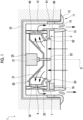
Fig. 1 is a cross-sectional view of a ceiling-embedded air conditioner according to a first embodiment of the present disclosure. -
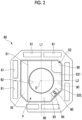
Fig. 2 is a schematic view of a drain pan according to the first embodiment of the present disclosure as viewed in the direction of the axis. -
Fig. 3 is an enlarged cross-sectional view of a main part of the ceiling-embedded air conditioner according to the first embodiment of the present disclosure. -
Fig. 4 is a cross-sectional view showing a configuration of a refrigerant sensor according to the first embodiment of the present disclosure. -
Fig. 5 is an enlarged cross-sectional view of a main part of the ceiling-embedded air conditioner according to a first modification example of the first embodiment of the present disclosure. -
Fig. 6 is an enlarged cross-sectional view of a main part of a ceiling-embedded air conditioner according to a second modification example of the first embodiment of the present disclosure. -
Fig. 7 is a view of a drain pan according to a second embodiment of the present disclosure as viewed from below. - Hereinafter, a ceiling-embedded
air conditioner 1 according to a first embodiment of the present disclosure will be described with reference toFigs. 1 to 4 . - As shown in
Fig. 1 , the ceiling-embeddedair conditioner 1 includes amain body case 10, amotor 20, aturbofan 30, aheat exchanger 40, abell mouth 50, adrain pan 60, a mainelectrical box 70, a subelectrical box 80, and arefrigerant sensor 90. - The
main body case 10 is embedded in a ceiling of a building. Themain body case 10 has a rectangular shape as viewed from below, and is recessed upward to form a space therein. Specifically, themain body case 10 has apanel 11 that is exposed on a ceiling surface and aboxshaped cabinet 12 that is provided above thepanel 11. Thepanel 11 includes apanel body 13 that is a rectangular frame body, and agrill 14 provided in a lower center. Thepanel body 13 forms adischarge port 15 around thegrill 14. Thepanel body 13 and thegrill 14 are joined to each other in a state where they are removable downward from adrain pan 60 to be described later. - The
motor 20 is provided at a central portion of a bottom surface inside thecabinet 12 facing downward. Themotor 20 has amotor body 21 that accommodates a coil, a magnet, and the like, and anoutput shaft 22 that protrudes vertically downward from themotor body 21. Theoutput shaft 22 is rotationally driven about an axis O extending in the vertical direction. - The
turbofan 30 is attached to theoutput shaft 22. Theturbofan 30 includes a disk-shapedmain panel 31 that extends toward the radial outer side and has the axis O as the center, a plurality ofmain blades 32 that are arranged at intervals in the circumferential direction, and an annular-shaped shroud 33 that covers themain blades 32 from below. As theoutput shaft 22 rotates, theturbofan 30 fixed to theoutput shaft 22 by themain panel 31 rotates, and the air sucked from thegrill 14 passes through a bell mouth 50 (to be described later) and is sent to the radial outer side by theturbofan 30. - The annular-
shaped heat exchanger 40 that surrounds theturbofan 30 is provided on radial outer side of theturbofan 30. Theheat exchanger 40 is a portion of a refrigerant circuit having a refrigerating cycle. - The air sent to the
heat exchanger 40 by theturbofan 30 is heat-exchanged with a refrigerant when passing through theheat exchanger 40. Accordingly, the air that has flowed out to an outer peripheral side of theheat exchanger 40 becomes cold air or warm air. The air flows downward along a side surface of thecabinet 12, passes through anopening 61 of a drain pan 60 (to be described later), and is supplied to the room from adischarge port 15 of thepanel 11. - The
drain pan 60 provided below theheat exchanger 40 is a dish-shaped member for receiving the condensed water generated on the surface of theheat exchanger 40. Details will be described later, but a plurality ofopenings 61 for guiding the air that has passed through theheat exchanger 40 to thedischarge port 15 are formed in thedrain pan 60. A portion excluding theopenings 61 covers theheat exchanger 40 from below when viewed in a direction of the axis O. - The
bell mouth 50 is disposed below theturbofan 30. Thebell mouth 50 is provided to guide the air introduced from thegrill 14 and to send the air to theturbofan 30. Thebell mouth 50 has a conical shape that gradually contracts in diameter from below to above. An end portion of thebell mouth 50 on one side (upper side) in the direction of the axis O is surrounded by the above-describedshroud 33 from an outer peripheral side. - Next, the configuration of the
drain pan 60 will be described in detail. As shown inFig. 2 , thedrain pan 60 has a rectangular shape when viewed in the direction of the axis O. The four corners of thedrain pan 60 are formed with appropriate cutouts in accordance with the shape of themain body case 10. One or a plurality of (for example, two)openings 61 are formed in each of four edges of thedrain pan 60. - A
suction port 62 communicating with thebell mouth 50 described above is formed on a lower surface (that is, a surface facing the indoor side) of thedrain pan 60. Thesuction port 62 is a circular opening centered on the axis O. Further, an accommodation space V that is recessed upward is formed around thesuction port 62. The accommodation space V has a substantially rectangular shape when viewed in the direction of the axis O. The accommodation space V is partitioned into three areas by a first dividing line L1 and a second dividing line L2 that pass through the axis O. - The first dividing line L1 extends in a horizontal direction orthogonal to the axis O. The second dividing line L2 passes through the axis O and extends in the horizontal direction orthogonal to the first dividing line L1. Among two areas partitioned by the first dividing line L1, an area on one side (left side in the drawing) is a first area S1, and an area on the other side (right side in the drawing) is a second area S2.
- The second area S2 is further partitioned into two areas by the second dividing line L2. An area on one side (upper side in the drawing) of the second dividing line L2 is a first small area S21, and an area on the other side (lower side in the drawing) of the second dividing line L2 is a second small area S22.
- The main
electrical box 70 is provided in the first area S1. The mainelectrical box 70 accommodates electrical components such as an inverter for supplying power to themotor 20 and the like. As an example, the mainelectrical box 70 has a rectangular shape disposed along one edge (end edge) in the first area S1 of the accommodation space V or in contact with the edge. That is, the first dividing line L1 extends in the same direction (parallel direction) as a longitudinal direction of the mainelectrical box 70. The term "same direction or the parallel direction" as used herein means substantially the same and parallel, and slight manufacturing errors or design tolerances are allowed. - The sub
electrical box 80 is provided in the first small area S21 in the second area S2. The subelectrical box 80 accommodates, for example, an actuator or a relay circuit for moving thegrill 14 described above in the direction of the axis O. The subelectrical box 80 is disposed to be in contact with two edges forming a corner portion in the first small area S21. - In the second area S2, an
opening hole 63 for performing the maintenance is formed in the second small area S22. Theopening hole 63 is covered by acover 64. Theopening hole 63 and thecover 64 are disposed at a position separated from thesuction port 62 in the radial direction, at a central portion of the second small area S22 in the circumferential direction. That is, in the radial direction, the distance from the wall surface of the accommodation space V to thecover 64 is smaller than the distance from thesuction port 62 to thecover 64. Theopening hole 63 is used to replace an antibacterial agent (not illustrated) mounted on, for example, an upper surface side of thedrain pan 60. - As shown in
Fig. 3 , arefrigerant sensor 90 for detecting a refrigerant component contained in the air is provided on each of an upper surface and a lower surface of thecover 64. That is, therefrigerant sensor 90 is provided only in the second area S2 on the side opposite to the mainelectrical box 70 with the first dividing line L1 as a reference. Further, in the second area S2, therefrigerant sensor 90 is provided only in the second small area S22 on the side opposite to the subelectrical box 80 with reference to the second dividing line L2. In other words, therefrigerant sensor 90 is provided only in an area separated from the mainelectrical box 70 and the subelectrical box 80, and not in the vicinity of the mainelectrical box 70 and the subelectrical box 80. - The position where the
refrigerant sensor 90 is provided is not limited to the above-describedcover 64, and may be a position indicated by a rectangular broken line inFig. 2 . Specifically, therefrigerant sensor 90 may be disposed at a position slightly separated from the second dividing line L2 in the circumferential direction, or may be disposed at a position slightly separated from the first dividing line L1 in the circumferential direction. - As shown in
Fig. 4 , therefrigerant sensor 90 includes asensor body 91 as a sensor element, and ahousing 92 that covers thesensor body 91 from the outer side. Thehousing 92 has a rectangular parallelepiped shape, and a space for accommodating thesensor body 91 is formed inside thehousing 92. In addition, thehousing 92 is formed with aninflow port 93 and anoutflow port 94 for taking in air toward an internal space. A straight line connecting theinflow port 93 and theoutflow port 94 is a direction parallel to the radial direction with respect to the axis O. In addition, it is desirable that theinflow port 93 is located on the radial outer side and theoutflow port 94 is located on the radial inner side. The term "parallel" as used herein refers to substantial parallelism, and a manufacturing error is allowed. - Next, the operation of the ceiling-embedded
air conditioner 1 will be described. When the ceiling-embeddedair conditioner 1 is operated, power is first supplied to themotor 20. Accordingly, theoutput shaft 22 of themotor 20 is rotationally driven about the axis O. Then, theturbofan 30 attached to theoutput shaft 22 also rotates about the axis O. The air in the room is taken into theturbofan 30 through thegrill 14 as theturbofan 30 rotates. The air pumped by theturbofan 30 flows toward the radial outer side and comes into contact with theheat exchanger 40. Heat exchange between the refrigerant and the air of theheat exchanger 40 is performed, and the temperature of the air is regulated. The temperature-regulated air is supplied into the room through thedischarge port 15. - Here, the
refrigerant sensor 90 is provided in the ceiling-embeddedair conditioner 1 for the purpose of detecting a case where the refrigerant leaks from theheat exchanger 40. Therefrigerant sensor 90 detects the concentration of the refrigerant component contained in the air to detect the leakage. For this reason, it is desirable that therefrigerant sensor 90 is disposed at a location where the flow speed and the flow rate of the air are low so that therefrigerant sensor 90 is not contaminated with dust or dirt. - Therefore, in the present embodiment, as described above, the
refrigerant sensor 90 is disposed only in the second small area S22 which is an area separated from the mainelectrical box 70 and the subelectrical box 80, among the areas of each of the drain pans 60. In the first area S1 where the mainelectrical box 70 is disposed, the mainelectrical box 70 is disposed between thegrill 14 and thesuction port 62. Therefore, the volume of the accommodation space V, which is an air flow path, is small. In other words, a cross-sectional area of the flow path is reduced. Similarly, the cross-sectional area of the flow path is also reduced in the first small area S21 where the subelectrical box 80 is disposed. For this reason, the flow speed of the air increases as compared with that in other areas, and the flow rate also increases with the increase in the flow speed. As a result, in the vicinity of the mainelectrical box 70 and the sub electrical box 80 (that is, the first area S1 and the first small area S21), the amount of the dirt or the dust contained in the air is larger than that in the second small area S22. Therefore, there is a high possibility that therefrigerant sensor 90 may be contaminated with dust or dirt. However, in the present embodiment, therefrigerant sensor 90 is disposed only in the second small area S22 where the mainelectrical box 70 and the subelectrical box 80 are not provided. Therefore, the flow speed and the flow rate of the air in contact with therefrigerant sensor 90 can be suppressed to be small. As a result, the amount of the dirt or the dust adhering to therefrigerant sensor 90 is reduced. Therefore, it is possible to improve the accuracy of the leakage detection of the refrigerant by therefrigerant sensor 90. - Further, according to the above configuration, the
refrigerant sensor 90 is attached to thecover 64 that covers theopening hole 63 in the second small area S22. For this reason, when thecover 64 is removed and the maintenance of the inside of the device is performed through theopening hole 63, the maintenance of therefrigerant sensor 90 can be simultaneously performed. As a result, the maintainability of the ceiling-embeddedair conditioner 1 can be further improved. - In addition, according to the above configuration, the
refrigerant sensor 90 is attached to the lower surface side of thecover 64. Therefore, therefrigerant sensor 90 is immediately exposed to the outside when thegrill 14 is removed. Therefore, the visibility of therefrigerant sensor 90 during work is improved. In this manner, the maintenance of therefrigerant sensor 90 can be more easily and smoothly performed. - In addition, according to the above configuration, the
refrigerant sensor 90 is also attached to the upper surface side of thecover 64. Therefore, therefrigerant sensor 90 is exposed to the flow of the air having a smaller flow speed and a smaller flow rate than the flow of the air on the lower surface side of thecover 64. In this manner, it is possible to further reduce the possibility that therefrigerant sensor 90 is contaminated with the dirt or the dust. Therefore, the accuracy of detecting the leakage by therefrigerant sensor 90 can be further improved. - In addition, according to the above configuration, since the
inflow port 93 and theoutflow port 94 of thehousing 92 of therefrigerant sensor 90 are open in the direction parallel to the radial direction, the minimum amount of air required for detecting the refrigerant can be smoothly and continuously sent to thesensor body 91 in thehousing 92. Accordingly, it is possible to detect the leakage of the refrigerant with higher accuracy. - The first embodiment of the present disclosure has been described above. Various changes or improvements can be made to the above configuration without departing from the concept of the present disclosure. For example, in the first embodiment, an example has been described in which one
refrigerant sensor 90 is provided on each of the upper surface side and the lower surface side of thecover 64. However, as shown inFigs. 5 and6 , therefrigerant sensor 90 may be provided only on the upper surface side or only on the lower surface side of thecover 64. - Subsequently, a ceiling-embedded
air conditioner 101 according to a second embodiment of the present disclosure will be described with reference toFig. 7 . The same configurations as those of the first embodiment will be assigned with the same reference numerals, and detailed description thereof will be omitted. - As shown in
Fig. 7 , adrain pan 160 of the ceiling-embeddedair conditioner 101 has a rectangular shape. Twosuction ports 62 arranged at intervals from each other are formed on the lower surface of thedrain pan 160. In addition, the mainelectrical box 170 is disposed on an extension of a straight line connecting the twosuction ports 62. Further, oneopening 61 is formed on each of both sides of each of thesuction ports 62. - The lower surface of the
drain pan 60 is partitioned into two areas by a first dividing line L101 passing through the axis O of thesuction port 62 close to the mainelectrical box 170, among the twosuction ports 62. A side where the mainelectrical box 170 is located with reference to the first dividing line L101 is a first area S101, and an area on a side opposite to the first area S101 is a second area S102. The mainelectrical box 170 has a rectangular shape disposed to be in contact with one edge (end edge) in the first area S101. That is, the first dividing line L101 extends in the same direction (parallel direction) as the longitudinal direction of the mainelectrical box 170. The term "same direction or the parallel direction" as used herein means substantially the same and parallel, and slight manufacturing errors or design tolerances are allowed. - The
refrigerant sensor 90 is disposed in the second area S102. In the example ofFig. 7 , therefrigerant sensor 90 is provided between theopenings 61. In addition, therefrigerant sensor 90 may be disposed at each position indicated by a rectangular broken line in the drawing. Specifically, therefrigerant sensor 90 may be provided in an area between the end edge farthest from the mainelectrical box 170 in the second area S102 and thesuction port 62. - According to the above configuration, the
refrigerant sensor 90 is disposed only in the second area S102 which is an area separated from the mainelectrical box 170, among the areas of thedrain pan 60. In the first area S101 in which the mainelectrical box 170 is disposed, the mainelectrical box 70 is disposed between thegrill 14 and thesuction port 62. Therefore, the volume of the air flow path is small. In other words, a cross-sectional area of the flow path is reduced. For this reason, the flow speed of the air increases as compared with that in other areas, and the flow rate also increases with the increase in the flow speed. As a result, in the vicinity of the main electrical box 170 (that is, in the first area S101), the amount of the dirt or dust contained in the air is larger than that in the second area S102. Therefore, there is a high possibility that therefrigerant sensor 90 may be contaminated with dust or dirt. However, in the present embodiment, therefrigerant sensor 90 is disposed only in the second area S102 where the mainelectrical box 170 is not provided. Therefore, the flow speed and the flow rate of the air in contact with therefrigerant sensor 90 can be suppressed to be small. As a result, the amount of the dirt or the dust adhering to therefrigerant sensor 90 is reduced. Therefore, it is possible to improve the accuracy of the leakage detection of the refrigerant by therefrigerant sensor 90. - The second embodiment of the present disclosure has been described above. Various changes or improvements can be made to the above configuration without departing from the concept of the present disclosure.
- The ceiling-embedded
air conditioner 1 in each embodiment is grasped as follows, for example. - (1) The ceiling-embedded
air conditioner 1 according to a first aspect includes amotor 20 that has anoutput shaft 22 rotatable about an axis O extending in an up-down direction; aturbofan 30 that is attached to theoutput shaft 22; aheat exchanger 40 that surrounds theturbofan 30 from an outer peripheral side and through which air pumped by theturbofan 30 passes; adrain pan 60 that is provided below theheat exchanger 40 and is formed with asuction port 62 which is open about the axis O; a mainelectrical box 70 that is attached to a lower surface of thedrain pan 60 and accommodates an electrical component; and arefrigerant sensor 90 that is attached to thedrain pan 60 and detects a refrigerant in the air, in which a first area S1 in which the mainelectrical box 70 is disposed in one edge extending along a first dividing line L1 orthogonal to the axis O when viewed in a direction of the axis O, and a second area S2 located on a side opposite to the first area S1 with the first dividing line L1 interposed therebetween is formed on the lower surface of thedrain pan 60, and therefrigerant sensor 90 is provided in the second area S2.
According to the above configuration, therefrigerant sensor 90 is disposed in the second area S2 on the side opposite to the mainelectrical box 70. In the first area S1 where the mainelectrical box 70 is installed, the flow speed and the flow rate of the air flowing toward thesuction port 62 are large, while in the second area S2, the flow speed and the flow rate are relatively small. For this reason, it is possible to reduce the possibility that the dirt or the dust contained in the air adheres to therefrigerant sensor 90. - (2) The ceiling-embedded
air conditioner 1 according to a second aspect is the ceiling-embeddedair conditioner 1 of (1), in which the second area S2 is partitioned into a first small area S21 and a second small area S22 by a second dividing line L2 that is orthogonal to the first dividing line L1 and that extends in a horizontal direction, a subelectrical box 80 different from the mainelectrical box 70 is provided in the first small area S21, and therefrigerant sensor 90 is provided in the second small area S22.
According to the above configuration, therefrigerant sensor 90 is disposed in the second small area S22 in the second area S2. Since the subelectrical box 80 is disposed in the first small area S21, the flow speed and the flow rate of the air flowing toward thesuction port 62 are large, while the flow speed and the flow rate are relatively small in the second small area S22. For this reason, it is possible to further reduce the possibility that the dirt or dust contained in the air adheres to therefrigerant sensor 90. - (3) The ceiling-embedded
air conditioner 1 according to a third aspect is the ceiling-embeddedair conditioner 1 of (2), and further includes acover 64 detachably attached to anopening hole 63 formed in the second small area S22, in which therefrigerant sensor 90 is provided in thecover 64.
According to the above configuration, therefrigerant sensor 90 is attached to thecover 64 covering theopening hole 63. Therefore, when maintenance is performed through theopening hole 63, the maintenance of therefrigerant sensor 90 can be simultaneously performed. - (4) The ceiling-embedded
air conditioner 1 according to a fourth aspect is the ceiling-embeddedair conditioner 1 of (3), in which therefrigerant sensor 90 is provided on a lower surface side of thecover 64.
According to the above configuration, therefrigerant sensor 90 is attached to the lower surface side of thecover 64. Therefore, the visibility of therefrigerant sensor 90 is improved. In this manner, the maintenance of therefrigerant sensor 90 can be more easily and smoothly performed. - (5) The ceiling-embedded
air conditioner 1 according to a fifth aspect is the ceiling-embeddedair conditioner 1 of (3) or (4), in which therefrigerant sensor 90 is provided on an upper surface side of thecover 64.
According to the above configuration, therefrigerant sensor 90 is attached to the upper surface side of thecover 64. Therefore, therefrigerant sensor 90 is exposed to the flow of the air having a smaller flow speed and a smaller flow rate than the air on the lower surface side of thecover 64. In this manner, it is possible to further reduce the possibility that therefrigerant sensor 90 is contaminated with the dirt or the dust. - (6) The ceiling-embedded
air conditioner 1 according to a sixth aspect is the ceiling-embeddedair conditioner 1 according to any one of (1) to (5), in which therefrigerant sensor 90 includes asensor body 91 that detects a refrigerant component in the air, and ahousing 92 that covers thesensor body 91 from an outer side and in which aninflow port 93 through which the air is taken in and anoutflow port 94 through which the air flows out are formed, and theinflow port 93 and theoutflow port 94 are open in a direction parallel to a radial direction with respect to the axis O.
According to the above configuration, since theinflow port 93 and theoutflow port 94 of thehousing 92 of therefrigerant sensor 90 are open in the direction parallel to the radial direction, air can be smoothly sent to thesensor body 91. - (7) The ceiling-embedded air conditioner 1 according to a seventh aspect includes a motor 20 that has an output shaft 22 rotatable about an axis O extending in an up-down direction; a turbofan 30 that is attached to the output shaft 22; a heat exchanger 40 that surrounds the turbofan 30 from an outer peripheral side and through which air pumped by the turbofan 30 passes; a drain pan 60 that is provided below the heat exchanger 40 and is formed with a suction port 62 which is open about the axis O; a main electrical box 70 that is attached to a lower surface of the drain pan 60 and accommodates an electrical component; and a refrigerant sensor 90 that is attached to the drain pan 60 and detects a refrigerant in air, in which a first area S1 in which the main electrical box 70 is disposed in one edge extending along a first dividing line L1 orthogonal to the axis O when viewed in a direction of the axis O, and a second area S2 located on a side opposite to the first area S1 with the first dividing line L1 interposed therebetween is formed on the lower surface of the drain pan 60, the second area S2 is partitioned into a first small area S21 and a second small area S22 by a second dividing line L2 that is orthogonal to the first dividing line L1 and that extends in a horizontal direction, a sub electrical box 80 different from the main electrical box 70 is provided in the first small area S21, a cover 64 detachably attached to an opening hole 63 formed in the second small area S22 is further provided, and the refrigerant sensor 90 is provided on an upper surface side of the cover 64.
- According to the above configuration, the
refrigerant sensor 90 is attached to the upper surface side of thecover 64. Therefore, therefrigerant sensor 90 is exposed to the flow of the air having a smaller flow speed and a smaller flow rate than the air on the lower surface side of thecover 64. In this manner, it is possible to further reduce the possibility that therefrigerant sensor 90 is contaminated with the dirt or the dust. - In the ceiling-embedded
air conditioner 1, it is possible to detect the leakage of the refrigerant with higher accuracy. -
- 1: ceiling-embedded air conditioner
- 10: main body case
- 11: panel
- 12: cabinet
- 13: panel body
- 14: grill
- 15: discharge port
- 20: motor
- 21: motor body
- 22: output shaft
- 30: turbofan
- 31: main panel
- 32: main blade
- 33: shroud
- 40: heat exchanger
- 50: bell mouth
- 60: drain pan
- 61: opening
- 62: suction port
- 63: opening hole
- 64: cover
- 70: main electrical box
- 80: sub electrical box
- 90: refrigerant sensor
- 91: sensor body
- 92: housing
- 93: inflow port
- 94: outflow port
- 101: ceiling-embedded air conditioner
- 160: drain pan
- 170: main electrical box
- L1: first dividing line
- L101: first dividing line
- L2: second dividing line
- O: axis
- S1: first area
- S101: first area
- S102: second area
- S2: second area
- S21: first small area
- S22: second small area
- V: accommodation space
Claims (7)
- A ceiling-embedded air conditioner comprising:a motor that has an output shaft rotatable about an axis extending in an up-down direction;a turbofan that is attached to the output shaft;a heat exchanger that surrounds the turbofan from an outer peripheral side and through which air pumped by the turbofan passes;a drain pan that is provided below the heat exchanger and is formed with a suction port which is open about the axis;a main electrical box that is attached to a lower surface of the drain pan and accommodates an electrical component; anda refrigerant sensor that is attached to the drain pan and detects a refrigerant in the air,wherein a first area in which the main electrical box is disposed in one edge extending along a first dividing line orthogonal to the axis when viewed in a direction of the axis, and a second area located on a side opposite to the first area with the first dividing line interposed therebetween is formed on the lower surface of the drain pan, andthe refrigerant sensor is provided in the second area.
- The ceiling-embedded air conditioner according to Claim 1,wherein the second area is partitioned into a first small area and a second small area by a second dividing line that is orthogonal to the first dividing line and that extends in a horizontal direction,a sub electrical box different from the main electrical box is provided in the first small area, and the refrigerant sensor is provided in the second small area.
- The ceiling-embedded air conditioner according to Claim 2, further comprising:a cover detachably attached to an opening hole formed in the second small area,wherein the refrigerant sensor is provided in the cover.
- The ceiling-embedded air conditioner according to Claim 3,
wherein the refrigerant sensor is provided on a lower surface side of the cover. - The ceiling-embedded air conditioner according to Claim 3 or 4,
wherein the refrigerant sensor is provided on an upper surface side of the cover. - The ceiling-embedded air conditioner according to any one of Claims 1 to 5,wherein the refrigerant sensor includesa sensor body that detects a refrigerant component in the air, anda housing that covers the sensor body from an outer side and in which an inflow port through which the air is taken in and an outflow port through which the air flows out are formed, andthe inflow port and the outflow port are open in a direction parallel to a radial direction with respect to the axis.
- A ceiling-embedded air conditioner comprising:a motor that has an output shaft rotatable about an axis extending in an up-down direction;a turbofan that is attached to the output shaft;a heat exchanger that surrounds the turbofan from an outer peripheral side and through which air pumped by the turbofan passes;a drain pan that is provided below the heat exchanger and is formed with a suction port which is open about the axis;a main electrical box that is attached to a lower surface of the drain pan and accommodates an electrical component; anda refrigerant sensor that is attached to the drain pan and detects a refrigerant in air,wherein a first area in which the main electrical box is disposed in one edge extending along a first dividing line orthogonal to the axis when viewed in a direction of the axis, and a second area located on a side opposite to the first area with the first dividing line interposed therebetween is formed on the lower surface of the drain pan,the second area is partitioned into a first small area and a second small area by a second dividing line that is orthogonal to the first dividing line and that extends in a horizontal direction,a sub electrical box different from the main electrical box is provided in the first small area,a cover detachably attached to an opening hole formed in the second small area is further provided, andthe refrigerant sensor is provided on an upper surface side of the cover.
Applications Claiming Priority (1)
| Application Number | Priority Date | Filing Date | Title |
|---|---|---|---|
| PCT/JP2022/009745 WO2023170748A1 (en) | 2022-03-07 | 2022-03-07 | Ceiling-embedded air conditioner |
Publications (2)
| Publication Number | Publication Date |
|---|---|
| EP4474723A1 true EP4474723A1 (en) | 2024-12-11 |
| EP4474723A4 EP4474723A4 (en) | 2025-03-05 |
Family
ID=83658133
Family Applications (1)
| Application Number | Title | Priority Date | Filing Date |
|---|---|---|---|
| EP22930734.3A Pending EP4474723A4 (en) | 2022-03-07 | 2022-03-07 | CEILING-MOUNTED AIR CONDITIONER |
Country Status (3)
| Country | Link |
|---|---|
| EP (1) | EP4474723A4 (en) |
| JP (1) | JP7155459B1 (en) |
| WO (1) | WO2023170748A1 (en) |
Family Cites Families (10)
| Publication number | Priority date | Publication date | Assignee | Title |
|---|---|---|---|---|
| JP2003074900A (en) * | 2001-08-30 | 2003-03-12 | Hitachi Ltd | Air conditioner indoor unit |
| JP5305800B2 (en) * | 2008-09-17 | 2013-10-02 | 三洋電機株式会社 | Air conditioner |
| JP6448981B2 (en) * | 2014-10-23 | 2019-01-09 | 日立ジョンソンコントロールズ空調株式会社 | Air conditioner indoor unit |
| JP7332273B2 (en) * | 2018-02-09 | 2023-08-23 | 三菱重工サーマルシステムズ株式会社 | air conditioner |
| WO2019162993A1 (en) * | 2018-02-20 | 2019-08-29 | 三菱電機株式会社 | Indoor unit for air conditioner and air conditioner comprising same indoor unit |
| JP6949217B2 (en) * | 2018-06-08 | 2021-10-13 | 三菱電機株式会社 | Indoor unit of air conditioner and air conditioner |
| JP6866906B2 (en) * | 2019-07-12 | 2021-04-28 | ダイキン工業株式会社 | Refrigeration cycle system |
| JP6922947B2 (en) | 2019-07-12 | 2021-08-18 | ダイキン工業株式会社 | Indoor unit of refrigeration equipment |
| WO2021090810A1 (en) * | 2019-11-05 | 2021-05-14 | ダイキン工業株式会社 | Air conditioning indoor unit and air conditioner |
| CN212511464U (en) * | 2020-05-29 | 2021-02-09 | 广东美的制冷设备有限公司 | Ceiling machine and electric control and humidity detection combined assembly thereof |
-
2022
- 2022-03-07 EP EP22930734.3A patent/EP4474723A4/en active Pending
- 2022-03-07 JP JP2022527103A patent/JP7155459B1/en active Active
- 2022-03-07 WO PCT/JP2022/009745 patent/WO2023170748A1/en not_active Ceased
Also Published As
| Publication number | Publication date |
|---|---|
| EP4474723A4 (en) | 2025-03-05 |
| WO2023170748A1 (en) | 2023-09-14 |
| JP7155459B1 (en) | 2022-10-18 |
| JPWO2023170748A1 (en) | 2023-09-14 |
Similar Documents
| Publication | Publication Date | Title |
|---|---|---|
| CN107110540B (en) | Air conditioner | |
| CN105509145B (en) | Ceiling embedded type air conditioner | |
| JP7481489B2 (en) | Ceiling-mounted air conditioning unit for a heat pump with a refrigerant circuit having a refrigerant leak sensor | |
| JP6519360B2 (en) | Indoor unit of air conditioner | |
| EP3412984A1 (en) | Indoor unit for air conditioners | |
| CN105509144A (en) | Ceiling-embedded air conditioner | |
| JP2014047970A (en) | Refrigerant pipe structure of air conditioner | |
| EP3604944B1 (en) | Ventilation device | |
| JP7155459B1 (en) | Ceiling-mounted air conditioner | |
| JP7422312B2 (en) | Ceiling-mounted indoor unit | |
| CN203454366U (en) | Air conditioner | |
| JP2023108474A (en) | indoor unit | |
| US20210239329A1 (en) | Ceiling-embedded air conditioner | |
| JP2007127391A (en) | Ventilation equipment | |
| US11112142B2 (en) | Cover assembly for an opening in a bulkhead of an air conditioner unit | |
| EP4068579A1 (en) | Motor, motor assembly, and air conditioning apparatus | |
| US12000601B2 (en) | Air-conditioning apparatus | |
| JP2013092304A (en) | Indoor unit of air conditioner | |
| WO2009133909A1 (en) | Indoor unit for air conditioner | |
| JP2018119713A (en) | Ceiling-embedded air conditioner | |
| EP4160098A1 (en) | Indoor unit | |
| JPH10196988A (en) | Air conditioner indoor unit | |
| CN114391081B (en) | Outdoor unit of refrigerating apparatus | |
| JP2003240257A (en) | Indoor unit of air conditioning device | |
| US20240230111A1 (en) | Indoor unit and air conditioner |
Legal Events
| Date | Code | Title | Description |
|---|---|---|---|
| STAA | Information on the status of an ep patent application or granted ep patent |
Free format text: STATUS: THE INTERNATIONAL PUBLICATION HAS BEEN MADE |
|
| PUAI | Public reference made under article 153(3) epc to a published international application that has entered the european phase |
Free format text: ORIGINAL CODE: 0009012 |
|
| STAA | Information on the status of an ep patent application or granted ep patent |
Free format text: STATUS: REQUEST FOR EXAMINATION WAS MADE |
|
| 17P | Request for examination filed |
Effective date: 20240903 |
|
| AK | Designated contracting states |
Kind code of ref document: A1 Designated state(s): AL AT BE BG CH CY CZ DE DK EE ES FI FR GB GR HR HU IE IS IT LI LT LU LV MC MK MT NL NO PL PT RO RS SE SI SK SM TR |
|
| A4 | Supplementary search report drawn up and despatched |
Effective date: 20250131 |
|
| RIC1 | Information provided on ipc code assigned before grant |
Ipc: F24F 13/06 20060101ALN20250127BHEP Ipc: F25B 13/00 20060101ALI20250127BHEP Ipc: F24F 11/36 20180101ALI20250127BHEP Ipc: F24F 1/0047 20190101ALI20250127BHEP Ipc: F24F 13/20 20060101ALI20250127BHEP Ipc: F24F 11/89 20180101AFI20250127BHEP |
|
| DAV | Request for validation of the european patent (deleted) | ||
| DAX | Request for extension of the european patent (deleted) |