EP4474707A1 - Combustion device and gas turbine system - Google Patents
Combustion device and gas turbine system Download PDFInfo
- Publication number
- EP4474707A1 EP4474707A1 EP22924070.0A EP22924070A EP4474707A1 EP 4474707 A1 EP4474707 A1 EP 4474707A1 EP 22924070 A EP22924070 A EP 22924070A EP 4474707 A1 EP4474707 A1 EP 4474707A1
- Authority
- EP
- European Patent Office
- Prior art keywords
- injection hole
- combustion chamber
- hole group
- air
- burner plate
- Prior art date
- Legal status (The legal status is an assumption and is not a legal conclusion. Google has not performed a legal analysis and makes no representation as to the accuracy of the status listed.)
- Pending
Links
Images




Classifications
-
- F—MECHANICAL ENGINEERING; LIGHTING; HEATING; WEAPONS; BLASTING
- F23—COMBUSTION APPARATUS; COMBUSTION PROCESSES
- F23R—GENERATING COMBUSTION PRODUCTS OF HIGH PRESSURE OR HIGH VELOCITY, e.g. GAS-TURBINE COMBUSTION CHAMBERS
- F23R3/00—Continuous combustion chambers using liquid or gaseous fuel
- F23R3/002—Wall structures
-
- F—MECHANICAL ENGINEERING; LIGHTING; HEATING; WEAPONS; BLASTING
- F23—COMBUSTION APPARATUS; COMBUSTION PROCESSES
- F23R—GENERATING COMBUSTION PRODUCTS OF HIGH PRESSURE OR HIGH VELOCITY, e.g. GAS-TURBINE COMBUSTION CHAMBERS
- F23R3/00—Continuous combustion chambers using liquid or gaseous fuel
- F23R3/02—Continuous combustion chambers using liquid or gaseous fuel characterised by the air-flow or gas-flow configuration
- F23R3/04—Air inlet arrangements
- F23R3/06—Arrangement of apertures along the flame tube
-
- F—MECHANICAL ENGINEERING; LIGHTING; HEATING; WEAPONS; BLASTING
- F23—COMBUSTION APPARATUS; COMBUSTION PROCESSES
- F23R—GENERATING COMBUSTION PRODUCTS OF HIGH PRESSURE OR HIGH VELOCITY, e.g. GAS-TURBINE COMBUSTION CHAMBERS
- F23R3/00—Continuous combustion chambers using liquid or gaseous fuel
- F23R3/02—Continuous combustion chambers using liquid or gaseous fuel characterised by the air-flow or gas-flow configuration
- F23R3/04—Air inlet arrangements
- F23R3/10—Air inlet arrangements for primary air
-
- F—MECHANICAL ENGINEERING; LIGHTING; HEATING; WEAPONS; BLASTING
- F23—COMBUSTION APPARATUS; COMBUSTION PROCESSES
- F23R—GENERATING COMBUSTION PRODUCTS OF HIGH PRESSURE OR HIGH VELOCITY, e.g. GAS-TURBINE COMBUSTION CHAMBERS
- F23R3/00—Continuous combustion chambers using liquid or gaseous fuel
- F23R3/28—Continuous combustion chambers using liquid or gaseous fuel characterised by the fuel supply
-
- F—MECHANICAL ENGINEERING; LIGHTING; HEATING; WEAPONS; BLASTING
- F23—COMBUSTION APPARATUS; COMBUSTION PROCESSES
- F23R—GENERATING COMBUSTION PRODUCTS OF HIGH PRESSURE OR HIGH VELOCITY, e.g. GAS-TURBINE COMBUSTION CHAMBERS
- F23R3/00—Continuous combustion chambers using liquid or gaseous fuel
- F23R3/42—Continuous combustion chambers using liquid or gaseous fuel characterised by the arrangement or form of the flame tubes or combustion chambers
- F23R3/50—Combustion chambers comprising an annular flame tube within an annular casing
Definitions
- the present disclosure relates to a combustion device and a gas turbine system.
- This application claims the benefit of priority to Japanese Patent Application No. 2022-13189 filed on January 31, 2022 , and contents thereof are incorporated herein.
- a gas turbine system that combusts fuel in a combustor to obtain power has been used.
- the gas turbine system for example, there exists a gas turbine system that uses hydrogen as fuel, as disclosed in Patent Literature 1. Emission of carbon dioxide is suppressed by using hydrogen as fuel.
- Patent Literature 1 JP 2015-014400 A
- a plate facing a combustion chamber in which hydrogen is burned, is manufactured using additive manufacturing technology in some cases.
- a metal lamination amount of the plate on the combustion chamber side is larger than a metal lamination amount of the plate on a side opposite to the combustion chamber.
- the metal shrinks.
- the plate may deform to the combustion chamber side due to a shrinkage force on the side with the larger metal lamination amount.
- An object of the present disclosure is to provide a combustion device and a gas turbine system that are capable of suppressing deformation of a plate.
- a combustion device including: a plate facing a combustion chamber; a plurality of injection hole groups formed in the plate so as to have an annular shape; and a slit having an annular shape and formed between the plurality of injection hole groups.
- the plurality of injection hole groups may include a first injection hole group and a second injection hole group.
- the first injection hole group includes: a plurality of fuel injection holes facing an interior of the combustion chamber and formed so as to be spaced apart from each other in a circumferential direction of the combustion chamber; a first air injection hole having an annular shape, facing the interior of the combustion chamber, and extending in the circumferential direction on a radially outer side with respect to the plurality of fuel injection holes; and a second air injection hole having an annular shape, facing the interior of the combustion chamber, and extending in the circumferential direction on a radially inner side with respect to the plurality of fuel injection holes.
- the second injection hole group faces the interior of the combustion chamber, and includes fuel injection holes, a first air injection hole, and a second air injection hole.
- the second injection hole group is located radially inward of the first injection hole group.
- the combustion device may further include an annular cavity that is formed between the plurality of injection hole groups in the plate, and communicates with the slit.
- the combustion device may further include a through-hole that is formed in the plate on a side opposite to the combustion chamber, and communicates with the annular cavity.
- the through-hole may be displaced in a radial direction with respect to the slit.
- a gas turbine system including the combustion device described above.
- deformation of the plate can be suppressed.
- FIG. 1 is a schematic view for illustrating a configuration of a gas turbine system 1 according to an embodiment.
- the gas turbine system 1 includes a turbocharger 11, a power generator 12, a combustor 13, a burner 14, a hydrogen tank 15, and a flow rate control valve 16.
- the combustor 13, the burner 14, the hydrogen tank 15, and the flow rate control valve 16 are included in a combustion device 10.
- the turbocharger 11 includes a compressor 11a and a turbine 11b.
- the compressor 11a and the turbine 11b rotate integrally.
- the compressor 11a and the turbine 11b are connected by a shaft.
- the compressor 11a is provided in an intake flow passage 21 connected to the combustor 13. Air to be supplied to the combustor 13 flows through the intake flow passage 21.
- An intake port (not shown) is formed at an upstream-side end portion of the intake flow passage 21. The intake port allows air to be introduced from an outside. The air introduced through the intake port passes through the compressor 11a and is sent to the combustor 13. The compressor 11a compresses the air and discharges the compressed air to a downstream side.
- the turbine 11b is provided in an exhaust flow passage 22 connected to the combustor 13.
- An exhaust gas discharged from the combustor 13 flows through the exhaust flow passage 22.
- An exhaust port (not shown) is formed at a downstream-side end portion of the exhaust flow passage 22. The exhaust port allows the exhaust gas to be discharged to the outside.
- the exhaust gas discharged from the combustor 13 passes through the turbine 11b and is sent to the exhaust port.
- the turbine 11b is rotated by the exhaust gas to generate rotational power.
- the power generator 12 is connected to the turbocharger 11.
- the power generator 12 generates electric power with use of the rotational power generated by the turbocharger 11.
- the combustor 13 includes a casing 13a, a liner 13b, and a combustion chamber 13c.
- the casing 13a has a substantially cylindrical shape.
- the liner 13b is provided inside the casing 13a.
- the liner 13b has a substantially cylindrical shape.
- the liner 13b is arranged coaxially with the casing 13a.
- the combustion chamber 13c is formed inside the liner 13b. That is, an interior space of the liner 13b corresponds to the combustion chamber 13c.
- the combustion chamber 13c is a space having a substantially cylindrical shape.
- the exhaust flow passage 22 is connected to the combustion chamber 13c.
- the burner 14 includes a burner plate (plate) 14a and a plurality of fuel supply pipes 14b.
- the burner plate 14a faces the combustion chamber 13c.
- the burner plate 14a seals the opening in the end portion of the liner 13b. That is, the burner plate 14a seals an end portion of the combustion chamber 13c.
- the burner plate 14a has a disk shape.
- the shape of the burner plate 14a is not limited thereto, and the burner plate 14a may have a shape other than a disk shape.
- the burner plate 14a may have a polygonal shape.
- the burner plate 14a may be formed of a plurality of separate pieces obtained by dividing a circular or polygonal plate.
- the burner plate 14a is formed by metal lamination molding.
- the fuel supply pipes 14b are connected to a surface of the burner plate 14a on a side opposite to the combustion chamber 13c. In other words, the fuel supply pipes 14b are connected to the surface of the burner plate 14a facing the space S.
- the fuel supply pipes 14b extend through the casing 13a to an outside of the casing 13a. In FIG. 1 , three fuel supply pipes 14b are illustrated. However, the number of the fuel supply pipes 14b is not limited.
- the burner plate 14a has fuel injection holes (specifically, fuel injection holes 31 to be described later) and air injection holes (specifically, first air injection holes 32 and second air injection holes 33 to be described later) formed therein.
- the fuel injection holes formed in the burner plate 14a communicate with the fuel supply pipes 14b.
- Hydrogen is fed as fuel into the fuel supply pipes 14b as described later.
- the hydrogen fed from the fuel supply pipes 14b to the burner plate 14a passes through the fuel injection holes of the burner plate 14a, and is injected into the combustion chamber 13c. As indicated by the single-dotted arrows in FIG.
- the air fed into the space S passes through the space S, and then reaches the surface of the burner plate 14a on the side opposite to the combustion chamber 13c.
- the air fed to the burner plate 14a passes through the air injection holes of the burner plate 14a, and is injected into the combustion chamber 13c.
- Hydrogen is stored in the hydrogen tank 15.
- the hydrogen may be liquid or gaseous.
- the hydrogen tank 15 is connected to the flow rate control valve 16 via a flow passage 23.
- the flow rate control valve 16 is connected to each fuel supply pipe 14b of the burner 14 via a flow passage 24.
- the hydrogen stored in the hydrogen tank 15 is supplied into the fuel supply pipes 14b via the flow passage 23, the flow rate control valve 16, and the flow passage 24.
- the flow rate control valve 16 controls (i.e., adjusts) a flow rate of the hydrogen to be supplied from the hydrogen tank 15 into the fuel supply pipes 14b. Through adjustment of an opening degree of the flow rate control valve 16, a supply amount of hydrogen from the hydrogen tank 15 into the fuel supply pipes 14b is adjusted.
- a circumferential direction of the combustion chamber 13c is also referred to simply as “circumferential direction”.
- a radial direction of the combustion chamber 13c is also referred to simply as “radial direction”.
- An axial direction of the combustion chamber 13c is also referred to simply as "axial direction”.
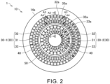
- FIG. 2 is a view of the burner plate 14a as seen from the combustion chamber 13c (specifically, from a direction of the arrow Al in FIG. 1 ).
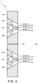
- FIG. 3 is a cross-sectional view taken along the line A2-A2 of FIG. 2 .
- FIG. 4 is a cross-sectional view taken along the line A3-A3 of FIG. 2 .
- FIG. 5 is a cross-sectional view taken along the line A4-A4 of FIG. 2 .
- a plurality of injection hole groups 30 are formed in the burner plate 14a.
- Each injection hole group 30 includes the plurality of fuel injection holes 31, the first air injection holes 32, and the second air injection holes 33.
- Each injection hole group 30 extends in the circumferential direction and has an annular shape.
- the first injection hole group 30-1 is arranged radially outward of the second injection hole group 30-2.
- the second injection hole group 30-2 is arranged radially inward of the first injection hole group 30-1.
- the first injection hole group 30-1 and the second injection hole group 30-2 are formed so as to be spaced apart from each other in the radial direction.
- the number of the injection hole groups 30 formed in the burner plate 14a is not limited to this example.
- the number of the injection hole groups 30 formed in the burner plate 14a may be one, or three or more.
- a configuration of the first injection hole group 30-1 and a configuration of the second injection hole group 30-2 are similar. Accordingly, the configuration of the first injection hole group 30-1 is described in detail below, and a detailed description of the configuration of the second injection hole group 30-2 is omitted.
- the fuel injection holes 31 face an interior of the combustion chamber 13c.
- the fuel injection holes 31 are opened in the surface of the burner plate 14a facing the combustion chamber 13c.
- the fuel injection holes 31 are hydrogen injection holes from which hydrogen is injected as fuel into the combustion chamber 13c.
- the plurality of fuel injection holes 31 are formed so as to be spaced apart from each other in the circumferential direction.
- the plurality of fuel injection holes 31 are formed at equal intervals. However, in each injection hole group 30, the plurality of fuel injection holes 31 may be formed at unequal intervals.
- a communication hole 40 is formed for each injection hole group 30.
- the communication hole 40 communicates with the plurality of fuel injection holes 31.
- the communication hole 40 extends in the circumferential direction.
- the communication hole 40 is formed into, for example, an annular shape.
- the communication hole 40 is aligned in the axial direction with the plurality of fuel injection holes 31 of each injection hole group 30.
- the communication hole 40 is arranged on the side opposite to the combustion chamber 13c with respect to the plurality of fuel injection holes 31 of each injection hole group 30.
- a transverse-sectional shape of the communication hole 40 (specifically, a shape in cross-section orthogonal to an extending direction of the communication hole 40) is circular.
- the transverse-sectional shape of the communication hole 40 may be a shape other than a circular shape (for example, a polygonal shape).
- the fuel supply pipes 14b of the burner 14 are connected to the communication hole 40. Hydrogen is supplied from the fuel supply pipes 14b to each of the communication holes 40. As indicated by the arrows C1 in FIG. 3 , the hydrogen supplied to the communication holes 40 is injected into the combustion chamber 13c from each fuel injection hole 31.
- the hydrogen supplied to the communication hole 40 of the first injection hole group 30-1 is injected into the combustion chamber 13c from the plurality of fuel injection holes 31 of the first injection hole group 30-1.
- the hydrogen supplied to the communication hole 40 of the second injection hole group 30-2 is injected into the combustion chamber 13c from the plurality of fuel injection holes 31 of the second injection hole group 30-2.
- the first air injection hole 32 faces the interior of the combustion chamber 13c.
- the first air injection hole 32 penetrates the burner plate 14a from the surface facing the combustion chamber 13c to the surface on the side opposite thereto.
- the first air injection hole 32 is formed on a radially outer side with respect to the plurality of fuel injection holes 31.
- the first air injection hole 32 extends in the circumferential direction and is formed into an annular shape.
- An outer diameter and an inner diameter of the first air injection hole 32 decrease from the side opposite to the combustion chamber 13c toward the combustion chamber 13c.
- a change amount in the inner diameter of the first air injection hole 32 is smaller than a change amount in the outer diameter of the first air injection hole 32.
- an opening area of the first air injection hole 32 on a side facing the combustion chamber 13c is smaller than an opening area thereof on a side opposite to the combustion chamber 13c.
- a center axis direction of the first air injection hole 32 is inclined toward the fuel injection holes 31 with respect to the axial direction, that is, inward in the radial direction. As indicated by the arrows C2 in FIG. 3 and FIG. 4 , part of the air fed through the space S in the combustor 13 to the burner plate 14a is injected from the first air injection holes 32 into the combustion chamber 13c.
- First swirling blades 32a that are inclined in the circumferential direction with respect to a combustion-chamber-side axial direction Dc are provided in the first air injection hole 32.
- the combustion-chamber-side axial direction Dc may also be referred to simply as "direction Dc".
- the direction Dc is a direction directed to the combustion chamber 13c along the axial direction of the combustion chamber 13c.
- To incline in the circumferential direction with respect to the direction Dc means to extend in a direction of a vector obtained by combining a vector of the circumferential direction with a vector of the direction Dc, or to incline so as to advance in the circumferential direction as the first swirling blades 32a approach the combustion chamber 13c.
- Each first swirling blade 32a has, for example, a substantially flat plate shape.
- the first swirling blades 32a partition the first air injection hole 32 in the circumferential direction.
- Each first swirling blade 32a extends on a plane that intersects the circumferential direction.
- the plurality of first swirling blades 32a are provided so as to be spaced apart from each other in the circumferential direction.
- the plurality of first swirling blades 32a are provided at equal intervals. However, in each first air injection hole 32, the plurality of first swirling blades 32a may be provided at unequal intervals.
- the first swirling blades 32a are inclined to one side in the circumferential direction (clockwise direction in FIG. 2 ) with respect to the direction Dc.
- the direction of the air to be injected from the first air injection hole 32 is along the first swirling blades 32a.
- the direction of the air to be injected from the first air injection hole 32 of the first injection hole group 30-1 is inclined to the one side in the circumferential direction with respect to the direction Dc.
- the air injected from the first air injection hole 32 of the first injection hole group 30-1 swirls to the one side in the circumferential direction in the combustion chamber 13c.
- the second air injection hole 33 faces the interior of the combustion chamber 13c.
- the second air injection hole 33 penetrates the burner plate 14a from the surface facing the combustion chamber 13c to the surface on the side opposite thereto.
- the second air injection hole 33 is formed on a radially inner side with respect to the plurality of fuel injection holes 31.
- the second air injection hole 33 extends in the circumferential direction and is formed into an annular shape.
- An outer diameter and an inner diameter of the second air injection hole 33 increase from the side opposite to the combustion chamber 13c toward the combustion chamber 13c.
- a change amount in the outer diameter of the second air injection hole 33 is smaller than a change amount in the inner diameter of the second air injection hole 33.
- an opening area of the second air injection hole 33 on a side facing the combustion chamber 13c is smaller than an opening area thereof on a side opposite to the combustion chamber 13c.
- a center axis direction of the second air injection hole 33 is inclined toward the fuel injection holes 31 with respect to the axial direction, that is, outward in the radial direction. As indicated by the arrows C3 in FIG. 3 and FIG. 5 , part of the air fed through the space S in the combustor 13 to the burner plate 14a is injected from the second air injection hole 33 into the combustion chamber 13c.
- Second swirling blades 33a that are inclined to the same side in the circumferential direction with respect to the direction Dc as in the first swirling blades 32a (specifically, the first swirling blades 32a belonging to the same injection hole group 30) are provided in the second air injection hole 33.
- Each second swirling blade 33a has, for example, a substantially flat plate shape.
- the second swirling blades 33a partition the second air injection hole 33 in the circumferential direction.
- Each second swirling blade 33a extends on a plane that intersects the circumferential direction.
- the plurality of second swirling blades 33a are provided so as to be spaced apart from each other in the circumferential direction.
- the plurality of second swirling blades 33a are provided at equal intervals. However, in each second air injection hole 33, the plurality of second swirling blades 33a may be provided at unequal intervals.
- the second swirling blades 33a are inclined to the one side in the circumferential direction (clockwise direction in FIG. 2 ) with respect to the direction Dc.
- the direction of the air to be injected from the second air injection hole 33 is along the second swirling blades 33a.
- the direction of the air to be injected from the second air injection hole 33 of the first injection hole group 30-1 is inclined to the one side in the circumferential direction with respect to the direction Dc.
- the air injected from the second air injection hole 33 of the first injection hole group 30-1 swirls to the one side in the circumferential direction in the combustion chamber 13c.
- the direction of inclination of the first swirling blades 32a and the second swirling blades 33a in the first injection hole group 30-1 with respect to the direction Dc, and the direction of inclination of the first swirling blades 32a and the second swirling blades 33a in the second injection hole group 30-2 with respect to the direction Dc are on sides different from each other in the circumferential direction. That is, in the first air injection hole 32 of the second injection hole group 30-2, the first swirling blades 32a are inclined to the other side in the circumferential direction (counterclockwise direction in FIG. 2 ) with respect to the direction Dc. Accordingly, as indicated by the arrow B3 in FIG.
- the air injected from the first air injection hole 32 of the second injection hole group 30-2 swirls to the other side in the circumferential direction in the combustion chamber 13c.
- the second swirling blades 33a are inclined to the other side in the circumferential direction with respect to the direction Dc. Accordingly, as indicated by the arrow B4 in FIG. 2 , the air injected from the second air injection hole 33 of the second injection hole group 30-2 swirls to the other side in the circumferential direction in the combustion chamber 13c.
- the direction of inclination of the first swirling blades 32a and the second swirling blades 33a in the first injection hole group 30-1 with respect to the direction Dc, and the direction of inclination of the first swirling blades 32a and the second swirling blades 33a in the second injection hole group 30-2 with respect to the direction Dc may be on the same side in the circumferential direction.
- a case in which the direction of inclination of the first swirling blades 32a and the second swirling blades 33a in the first injection hole group 30-1 with respect to the direction Dc, and the direction of inclination of the first swirling blades 32a and the second swirling blades 33a in the second injection hole group 30-2 with respect to the direction Dc are on the same side in the circumferential direction is referred to as "inclination pattern 1".
- the first swirling blades 32a and the second swirling blades 33a in the first injection hole group 30-1 are inclined to the one side in the circumferential direction (clockwise direction in FIG. 2 ) with respect to the direction Dc.
- first swirling blades 32a and the second swirling blades 33a in the second injection hole group 30-2 are inclined to the one side in the circumferential direction (clockwise direction in FIG. 2 ) with respect to the direction Dc.
- the first swirling blades 32a and the second swirling blades 33a in the first injection hole group 30-1 may be inclined to the other side in the circumferential direction (counterclockwise direction in FIG. 2 ) with respect to the direction Dc.
- the first swirling blades 32a and the second swirling blades 33a in the second injection hole group 30-2 may be inclined to the other side in the circumferential direction (counterclockwise direction in FIG. 2 ) with respect to the direction Dc.
- the direction of inclination of the first swirling blades 32a and the second swirling blades 33a in the first injection hole group 30-1 with respect to the direction Dc in the present embodiment is opposite in the circumferential direction to the direction of inclination of the first swirling blades 32a and the second swirling blades 33a in the second injection hole group 30-2 with respect to direction Dc.
- a case in which the direction of inclination of the first swirling blades 32a and the second swirling blades 33a in the first injection hole group 30-1, and the direction of inclination of the first swirling blades 32a and the second swirling blades 33a in the second injection hole group 30-2 are inclined in directions opposite to each other as described above is referred to as "inclination pattern 2".
- first swirling blades 32a and the second swirling blades 33a in the first injection hole group 30-1 are inclined to the one side in the circumferential direction (clockwise direction in FIG. 2 ) with respect to the direction Dc.
- first swirling blades 32a and the second swirling blades 33a in the second injection hole group 30-2 are inclined to the other side in the circumferential direction (counterclockwise direction in FIG. 2 ) with respect to the direction Dc.
- the first swirling blades 32a are provided to be inclined in the circumferential direction with respect to the direction Dc.
- the second swirling blades 33a are provided to be inclined in the same direction as in the first swirling blades 32a in the circumferential direction with respect to the direction Dc.
- inclination angles of the first swirling blades 32a and the second swirling blades 33a may be the same or different from each other.
- FIG. 6 is a schematic view for illustrating a flow of gas generated in the combustion chamber 13c.
- the swirling flow of air generated by the air injected from the first air injection holes 32 and the second air injection holes 33 is indicated by the arrow D1.
- a circulation flow which is a flow of gas passing near a center axis of the swirling flow (i.e., near a center axis of the combustion chamber 13c) toward the burner plate 14a.
- the direction of inclination of the first swirling blades 32a and the second swirling blades 33a in the first injection hole group 30-1 with respect to the direction Dc, and the direction of inclination of the first swirling blades 32a and the second swirling blades 33a in the second injection hole group 30-2 with respect to the direction Dc are on the sides different from each other in the circumferential direction.
- a direction (specifically, clockwise direction in FIG. 2 ) of the swirling flow generated by the air injected from the first injection hole group 30-1, and a direction (specifically, counterclockwise direction in FIG. 2 ) of the swirling flow generated by the air injected from the second injection hole group 30-2 are opposite to each other.
- the swirling flow generated by the air injected from the first injection hole group 30-1, and the swirling flow generated by the air injected from the second injection hole group 30-2 weaken each other.
- the circulation flow i.e., flow indicated by the arrows D2 in FIG. 6
- approach of flame to the burner plate 14a is suppressed. Accordingly, the melt loss of the burner 14 is suppressed.
- the first swirling blades 32a and the second swirling blades 33a of the first injection hole group 30-1 are inclined to the one side in the circumferential direction (clockwise direction in FIG. 2 ) with respect to the direction Dc.
- the first swirling blades 32a and the second swirling blades 33a of the first injection hole group 30-1 may be inclined to the other side in the circumferential direction (counterclockwise direction in FIG. 2 ) with respect to the direction Dc.
- the first swirling blades 32a and the second swirling blades 33a of the second injection hole group 30-2 are inclined to the one side in the circumferential direction with respect to the direction Dc.
- the direction of inclination of the first swirling blades 32a in the first injection hole group 30-1 with respect to the direction Dc may be on the same side in the circumferential direction as in the direction of inclination of the first swirling blades 32a in the second injection hole group 30-2 with respect to the direction Dc.
- the direction of inclination of the second swirling blades 33a in the first injection hole group 30-1 with respect to the direction Dc may be on the same side in the circumferential direction as in the direction of inclination of the second swirling blades 33a in the second injection hole group 30-2 with respect to the direction Dc.
- the direction of inclination of the first swirling blades 32a in the first injection hole group 30-1 and the second injection hole group 30-2 with respect to the direction Dc may be opposite to the direction of inclination of the second swirling blades 33a in the first injection hole group 30-1 and the second injection hole group 30-2 with respect to the direction Dc.
- a case in which the first swirling blades 32a in the first injection hole group 30-1 and the second injection hole group 30-2 and the second swirling blades 33a in the first injection hole group 30-1 and the second injection hole group 30-2 are thus inclined in directions opposite to each other is referred to as "inclination pattern 3".
- first swirling blades 32a of the first injection hole group 30-1 may be inclined to the one side in the circumferential direction (clockwise direction in FIG. 2 ) with respect to the direction Dc, and the second swirling blades 33a of the first injection hole group 30-1 may be inclined to the other side in the circumferential direction (counterclockwise in FIG. 2 ) with respect to the direction Dc.
- first swirling blades 32a of the second injection hole group 30-2 may be inclined to the one side in the circumferential direction (clockwise direction in FIG. 2 ) with respect to the direction Dc
- the second swirling blades 33a of the second injection hole group 30-2 may be inclined to the other side in the circumferential direction (counterclockwise direction in FIG.
- the direction of inclination of the first swirling blades 32a in the first injection hole group 30-1 with respect to the direction Dc may be on the side in the circumferential direction, which is opposite to the direction of inclination of the first swirling blades 32a in the second injection hole group 30-2 with respect to the direction Dc.
- the direction of inclination of the second swirling blades 33a in the first injection hole group 30-1 with respect to the direction Dc may be on the side in the circumferential direction, which is opposite to the direction of inclination of the second swirling blades 33a in the second injection hole group 30-2 with respect to the direction Dc.
- the direction of inclination of the first swirling blades 32a in the first injection hole group 30-1 and the second swirling blades 33a in the second injection hole group 30-2 with respect to the direction Dc may be opposite to the direction of inclination of the second swirling blades 33a in the first injection hole group 30-1 and the first swirling blades 32a in the second injection hole group 30-2 with respect to the direction Dc.
- a case in which the first swirling blades 32a in the first injection hole group 30-1 and the second swirling blades 33a in the second injection hole group 30-2, and the second swirling blades 33a in the first injection hole group 30-1 and the first swirling blades 32a in the second injection hole group 30-2 are thus inclined in directions opposite to each other is referred to as "inclination pattern 4".
- first swirling blades 32a of the first injection hole group 30-1 may be inclined to the one side in the circumferential direction (clockwise direction in FIG. 2 ) with respect to the direction Dc
- second swirling blades 33a of the first injection hole group 30-1 may be inclined to the other side in the circumferential direction (counterclockwise in FIG. 2 ) with respect to the direction Dc
- first swirling blades 32a of the second injection hole group 30-2 may be inclined to the other side in the circumferential direction (counterclockwise direction in FIG. 2 ) with respect to the direction Dc
- the second swirling blades 33a of the second injection hole group 30-2 may be inclined to the one side in the circumferential direction (clockwise direction in FIG.
- the injection hole groups 30 are formed in the burner plate 14a that seals the end portion of the combustion chamber 13c.
- the injection hole groups 30 can be easily formed.
- the burner plate 14a is thus integrally formed, as compared to a case in which a component forming the injection hole groups 30 is provided separately from the burner plate 14a, the structure of the burner 14 is simplified, the burner 14 is downsized, and manufacturing cost of the burner 14 is reduced. Further, leakage of hydrogen from joint portions of components is suppressed. In addition, occurrence of cracks in the joint portions due to thermal stress is suppressed.
- the communication hole 40 is formed in the burner plate 14a, and communicates with the plurality of fuel injection holes 31.
- the communication hole 40 can be easily formed.
- the structure of the burner 14 is simplified, the burner 14 is downsized, and the manufacturing cost of the burner 14 is reduced. Further, leakage of hydrogen from joint portions of components is suppressed. In addition, occurrence of cracks in the joint portions due to thermal stress is suppressed.
- a metal lamination amount on the surface of the burner plate 14a facing the combustion chamber 13c is larger than a metal lamination amount on the surface opposite to the combustion chamber 13c. This is because the opening areas of the first air injection hole 32 and the second air injection hole 33 in the surface facing the combustion chamber 13c are smaller than the opening areas in the surface opposite to the combustion chamber 13c.
- the metal shrinks. At this time, a shrinkage force on a side with a larger metal lamination amount may cause the burner plate 14a to deform to the combustion chamber side with the larger metal lamination amount.
- an annular slit 50 (see FIG. 2 and FIG. 3 ) is formed between the plurality of injection hole groups 30 of the burner plate 14a.
- the slit 50 is formed in the surface of the burner plate 14a facing the combustion chamber 13c.
- the slit 50 communicates with the combustion chamber 13c. That is, the slit 50 is opened toward the combustion chamber 13c.
- the slit 50 extends in the axial direction of the combustion chamber 13c. However, the slit 50 may extend obliquely to the axial direction of the combustion chamber 13c.
- a depth of the slit 50 is set so as to maintain a minimum thickness required to maintain strength of the burner plate 14a when the burner plate 14a is mounted to the liner 13b.
- the depth of the slit 50 is, for example, equal to or larger than a half of the thickness of the burner plate 14a.
- the depth of the slit 50 is, for example, equal to or larger than 4/5 of the thickness of the burner plate 14a.
- a radial position of the slit 50 is determined so that, for example, a mass of the burner plate 14a on a radially outer side with respect to the slit 50 is balanced with a mass of the burner plate 14a on a radially inner side with respect to the slit 50.
- the radial position of the slit 50 is set at a position where a radius of the slit 50 is larger than half a radius of the burner plate 14a.
- the radial position of the slit 50 may be set at a position where the radius is half the radius of the burner plate 14a or a position where the radius is smaller than half the radius of the burner plate 14a.
- the burner plate 14a has the slit 50, and thus the first injection hole group 30-1 and the second injection hole group 30-2 are divided by the slit 50 in the surface of the burner plate 14a facing the combustion chamber 13c. Therefore, the shrinkage force of the metal, which is generated as the temperature of the laminated metal decreases during the manufacture of the burner plate 14a, is divided between the radially inner side and the radially outer side of the slit 50. As a result, deformation of the burner plate 14a can be suppressed as compared to a case in which the slit 50 is not formed.
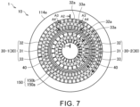
- FIG. 7 is a schematic cross-sectional view for illustrating a configuration of a burner plate 114a in a first modification example.
- Components substantially equivalent to those of the burner plate 14a in the above-mentioned embodiment are denoted by the same reference symbols, and descriptions thereof are omitted.
- the burner plate 114a in the first modification example differs from the burner plate of the above-mentioned embodiment in that a plurality of slits 150 are formed.
- the plurality of annular slits 150 are formed between the plurality of injection hole groups 30 of the burner plate 114a.
- the slits 150 are formed in the surface of the burner plate 114a facing the combustion chamber 13c.
- the slits 150 extend in the axial direction.
- the plurality of slits 150 include a first slit 150a and a second slit 150b. However, the present disclosure is not limited thereto, and the plurality of slits 150 may include three or more slits.
- the first slit 150a and the second slit 150b are formed so as to be spaced apart from each other in the radial direction.
- the first slit 150a is located radially outward of the second slit 150b.
- the second slit 150b is located radially inward of the first slit 150a.
- Depths of the first slit 150a and the second slit 150b are the same as those as given in the above-mentioned embodiment. However, the present disclosure is not limited thereto, and the depths of the first slit 150a and the second slit 150b may be different from those as given in the above-mentioned embodiment. Further, the depths of the first slit 150a and the second slit 150b may be different from each other.
- Radial positions of the first slit 150a and the second slit 150b are determined so that, for example, a mass of the burner plate 114a on a radially outer side of the first slit 150a is balanced with a mass of the burner plate 114a on a radially inner side of the second slit 150b.
- the radial position of the first slit 150a is set at a position where a radius of the first slit 150a is larger than half a radius of the burner plate 114a.
- the radial position of the second slit 150b is set at a position where a radius of the second slit 150b is smaller than half the radius of the burner plate 114a.
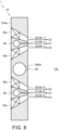
- FIG. 8 is a schematic cross-sectional view for illustrating a configuration of a burner plate 214a in a second modification example.
- Components substantially equivalent to those of the burner plate 14a in the above-mentioned embodiment are denoted by the same reference symbols, and descriptions thereof are omitted.
- the burner plate 214a in the second modification example differs from the burner plate of the above-mentioned embodiment in that an annular cavity 250A is formed.
- the annular cavity 250A is formed between the plurality of injection hole groups 30 of the burner plate 214a.
- the cavity 250A is separated from the injection hole groups 30 in the radial direction.
- the cavity 250A is formed in a substantially center of the burner plate 214a in a thickness direction thereof.
- the cavity 250A communicates with the slit 50.
- the cavity 250A has a circular transverse-sectional shape (shape in a cross-section including a center axis of the burner plate 214a).
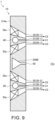
- FIG. 9 is a schematic cross-sectional view for illustrating a first shape example of a cavity 250B that is different from the cavity 250A in the second modification example.
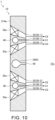
- FIG. 10 is a schematic cross-sectional view for illustrating a second shape example of a cavity 250C that is different from the cavity 250A in the second modification example.
- the cavity 250B has a triangular transverse-sectional shape.
- the cavity 250C has a water-drop-like transverse-sectional shape.
- the transverse-sectional shapes of the cavities 250A, 250B, and 250C are not limited to the shapes as illustrated in FIG. 8 to FIG. 10 , but may be, for example, a semi-circular shape, an elliptical shape, or an ellipsoidal shape.
- the cavities 250A, 250B, and 250C each have a curved surface on the side closer to the combustion chamber 13C, or a surface inclined from a plane perpendicular to the axial direction. In other words, the cavities 250A, 250B, and 250C each have no surface perpendicular to the axial direction on the side closer to the combustion chamber 13c.
- the burner plate 214a cannot be formed because portions corresponding to the cavities 250A, 250B, and 250C collapse during lamination using the additive manufacturing technology. Accordingly, in the second modification example, the cavities 250A, 250B, and 250C each have no surface perpendicular to the axial direction on the side closer to the combustion chamber 13c.
- a mass inside the burner plate 214a can be reduced.
- a metal deposition amount in the burner plate 214a can be reduced, and hence a weight of the burner plate 214a can be reduced.
- a degree of shrinkage that occurs when the metal is cooled during the manufacture of the burner plate 214a can be reduced.
- the deposition amount is reduced, and hence a time period required to form the burner plate 214a can be reduced.
- cost of the burner plate 214a can be reduced.
- work of mounting the burner plate 214a to the liner 13b is facilitated.
- FIG. 11 is a schematic cross-sectional view for illustrating a configuration of a burner plate 314a in a third modification example.
- Components substantially equivalent to the configurations of the burner plate 214a in the above-mentioned second modification example are denoted by the same reference symbols, and descriptions thereof are omitted.
- the burner plate 314a in the third modification example differs from the configuration of the above-mentioned second modification example in that through-holes 350 are formed.
- the through-holes 350 are formed between the plurality of injection hole groups 30 of the burner plate 314a.
- the through-holes 350 are formed on a side opposite to the combustion chamber 13c with respect to the cavity 250A.
- the through-holes 350 are separated from the injection hole groups 30 in the radial direction.
- the through-holes 350 extend in the axial direction. That is, the through-holes 350 extend in parallel to the slit 50.
- the present disclosure is not limited thereto, and the through-holes 350 may extend in a direction oblique to the axial direction.
- the plurality of through-holes 350 are formed in the radial direction.
- the present disclosure is not limited thereto, and only one through-hole 350 may be formed in the radial direction.
- the plurality of through-holes 350 are formed at equal intervals in the circumferential direction of the burner plate 314a.
- the present disclosure is not limited thereto, and the plurality of through-holes 350 may be formed at unequal intervals in the circumferential direction.
- the plurality of through-holes 350 allow communication between the space S and the cavity 250A.
- the plurality of through-holes 350 are displaced in the radial direction with respect to the slit 50. That is, the plurality of through-holes 350 are formed at positions offset from the slit 50 in the radial direction.
- the plurality of through-holes 350 can supply the air in the space S into the cavity 250A. This enables an interior of the cavity 250 to be cooled and the burner plate 314a to be cooled.
- the plurality of through-holes 350 are displaced in the radial direction with respect to the slit 50, and hence the air having passed through the through-holes 350 cannot be easily introduced directly into the slit 50. Accordingly, the air having passed through the through-holes 350 can be collided with an inner wall surface of the burner plate 314a that defines the cavity 250A. As a result, cooling of the burner plate 314a can be accelerated, and hence the melt loss of the burner plate 314a can be suppressed.
- the air supplied into the cavity 250A is supplied into the combustion chamber 13c via the slit 50. Accordingly, hydrogen flame formed near the burner plate 314a in the combustion chamber 13C can be prevented from approaching the burner plate 314a, and hence the melt loss of the burner plate 314a can be suppressed.
- the rotational power generated by the turbocharger 11 is used as energy for driving the power generator 12 in the gas turbine system 1.
- the present disclosure is not limited thereto.
- the combustion device 10 in the gas turbine system 1 may be applied to other combustion devices, such as a jet engine and an industrial furnace.
- the rotational power generated by the turbocharger 11 may be used for other purposes (e.g., for driving a moving object such as a ship).
- the shape of the combustion chamber 13c is a substantially cylindrical shape.
- the shape of the combustion chamber 13c is not limited to this example.
- the combustion chamber 13c may be a space having a substantially truncated cone shape.
- the shapes of the burner plates 14a, 114a, 214a, and 314a may be modified as appropriate in accordance with the shape of the combustion chamber 13c.
- the air fed from the compressor 11a to the combustor 13 is fed into the combustion chamber 13c after passing between an outer peripheral surface of the liner 13b and an inner peripheral surface of the casing 13a.
- the path of air fed from the compressor 11a to the combustor 13 is not limited to this example (i.e., turn-flow type).
- the burner plates (plates) 14a, 114a, 214a, and 314a are utilized in the gas turbine system 1.
- the burner plates 14a, 114a, 214a, and 314a may be utilized for systems other than the gas turbine system 1.
- the burner plates 14a, 114a, 214a, and 314a may be used as heat transfer plates in which flow passages for allowing water distribution are formed.
- the burner plates 14a, 114a, 214a, and 314a supply hydrogen into the combustion chamber 13c.
- the fuel to be supplied by the burner plates 14a, 114a, 214a, and 314a into the combustion chamber 13c is not limited to hydrogen, but may be, for example, natural gas.
Landscapes
- Engineering & Computer Science (AREA)
- Chemical & Material Sciences (AREA)
- Combustion & Propulsion (AREA)
- Mechanical Engineering (AREA)
- General Engineering & Computer Science (AREA)
- Pre-Mixing And Non-Premixing Gas Burner (AREA)
Abstract
Description
- The present disclosure relates to a combustion device and a gas turbine system. This application claims the benefit of priority to
Japanese Patent Application No. 2022-13189 filed on January 31, 2022 - A gas turbine system that combusts fuel in a combustor to obtain power has been used. As the gas turbine system, for example, there exists a gas turbine system that uses hydrogen as fuel, as disclosed in
Patent Literature 1. Emission of carbon dioxide is suppressed by using hydrogen as fuel. - Patent Literature 1:
JP 2015-014400 A - In recent years, in a gas turbine system, a plate facing a combustion chamber, in which hydrogen is burned, is manufactured using additive manufacturing technology in some cases. In such cases, a metal lamination amount of the plate on the combustion chamber side is larger than a metal lamination amount of the plate on a side opposite to the combustion chamber. As a temperature of the metal laminated during manufacture of the plate decreases, the metal shrinks. At this time, the plate may deform to the combustion chamber side due to a shrinkage force on the side with the larger metal lamination amount.
- An object of the present disclosure is to provide a combustion device and a gas turbine system that are capable of suppressing deformation of a plate.
- In order to achieve the above-mentioned object, according to the present disclosure, there is provided a combustion device including: a plate facing a combustion chamber; a plurality of injection hole groups formed in the plate so as to have an annular shape; and a slit having an annular shape and formed between the plurality of injection hole groups.
- The plurality of injection hole groups may include a first injection hole group and a second injection hole group. The first injection hole group includes: a plurality of fuel injection holes facing an interior of the combustion chamber and formed so as to be spaced apart from each other in a circumferential direction of the combustion chamber; a first air injection hole having an annular shape, facing the interior of the combustion chamber, and extending in the circumferential direction on a radially outer side with respect to the plurality of fuel injection holes; and a second air injection hole having an annular shape, facing the interior of the combustion chamber, and extending in the circumferential direction on a radially inner side with respect to the plurality of fuel injection holes. The second injection hole group faces the interior of the combustion chamber, and includes fuel injection holes, a first air injection hole, and a second air injection hole. The second injection hole group is located radially inward of the first injection hole group.
- The combustion device may further include an annular cavity that is formed between the plurality of injection hole groups in the plate, and communicates with the slit.
- The combustion device may further include a through-hole that is formed in the plate on a side opposite to the combustion chamber, and communicates with the annular cavity.
- The through-hole may be displaced in a radial direction with respect to the slit.
- In order to achieve the above-mentioned object, according to the present disclosure, there is provided a gas turbine system including the combustion device described above.
- According to the present disclosure, deformation of the plate can be suppressed.
-
-
FIG. 1 is a schematic view for illustrating a configuration of a gas turbine system according to an embodiment of the present disclosure. -
FIG. 2 is a view of a burner plate in the embodiment of the present disclosure as seen from a combustion chamber side. -
FIG. 3 is a cross-sectional view taken along the line A2-A2 ofFIG. 2 . -
FIG. 4 is a cross-sectional view taken along the line A3-A3 ofFIG. 2 . -
FIG. 5 is a cross-sectional view taken along the line A4-A4 ofFIG. 2 . -
FIG. 6 is a schematic view for illustrating a flow of gas generated in the combustion chamber in the embodiment of the present disclosure. -
FIG. 7 is a schematic cross-sectional view for illustrating a configuration of a burner plate in a first modification example. -
FIG. 8 is a schematic cross-sectional view for illustrating a configuration of a burner plate in a second modification example. -
FIG. 9 is a schematic cross-sectional view for illustrating a first shape example of a cavity that is different from a cavity in the second modification example. -
FIG. 10 is a schematic cross-sectional view for illustrating a second shape example of a cavity that is different from the cavity in the second modification example. -
FIG. 11 is a schematic cross-sectional view for illustrating a configuration of a burner plate in a third modification example. - Now, with reference to the attached drawings, an embodiment of the present disclosure is described. The dimensions, materials, and other specific numerical values represented in the embodiment are merely examples used for facilitating the understanding of the disclosure, and do not limit the present disclosure otherwise particularly noted. Elements having substantially the same functions and configurations herein and in the drawings are denoted by the same reference symbols to omit redundant description thereof. Further, illustration of elements with no direct relationship to the present disclosure is omitted.
-
FIG. 1 is a schematic view for illustrating a configuration of agas turbine system 1 according to an embodiment. As illustrated inFIG. 1 , thegas turbine system 1 includes aturbocharger 11, apower generator 12, acombustor 13, aburner 14, ahydrogen tank 15, and a flowrate control valve 16. - Of the
gas turbine system 1, thecombustor 13, theburner 14, thehydrogen tank 15, and the flowrate control valve 16 are included in acombustion device 10. - The
turbocharger 11 includes acompressor 11a and aturbine 11b. Thecompressor 11a and theturbine 11b rotate integrally. Thecompressor 11a and theturbine 11b are connected by a shaft. - The
compressor 11a is provided in anintake flow passage 21 connected to thecombustor 13. Air to be supplied to thecombustor 13 flows through theintake flow passage 21. An intake port (not shown) is formed at an upstream-side end portion of theintake flow passage 21. The intake port allows air to be introduced from an outside. The air introduced through the intake port passes through thecompressor 11a and is sent to thecombustor 13. Thecompressor 11a compresses the air and discharges the compressed air to a downstream side. - The
turbine 11b is provided in anexhaust flow passage 22 connected to thecombustor 13. An exhaust gas discharged from thecombustor 13 flows through theexhaust flow passage 22. An exhaust port (not shown) is formed at a downstream-side end portion of theexhaust flow passage 22. The exhaust port allows the exhaust gas to be discharged to the outside. The exhaust gas discharged from thecombustor 13 passes through theturbine 11b and is sent to the exhaust port. Theturbine 11b is rotated by the exhaust gas to generate rotational power. - The
power generator 12 is connected to theturbocharger 11. Thepower generator 12 generates electric power with use of the rotational power generated by theturbocharger 11. - The
combustor 13 includes acasing 13a, aliner 13b, and acombustion chamber 13c. Thecasing 13a has a substantially cylindrical shape. Theliner 13b is provided inside thecasing 13a. Theliner 13b has a substantially cylindrical shape. Theliner 13b is arranged coaxially with thecasing 13a. Thecombustion chamber 13c is formed inside theliner 13b. That is, an interior space of theliner 13b corresponds to thecombustion chamber 13c. Thecombustion chamber 13c is a space having a substantially cylindrical shape. Theexhaust flow passage 22 is connected to thecombustion chamber 13c. - As described later, hydrogen and air are supplied into the
combustion chamber 13c. In thecombustion chamber 13c, hydrogen is used as fuel to cause combustion. An exhaust gas generated as a result of combustion in thecombustion chamber 13c is discharged to theexhaust flow passage 22. A space S is defined between an inner surface of thecasing 13a and an outer surface of theliner 13b. Theintake flow passage 21 is connected to the space S. Air is fed into the space S from thecompressor 11a via theintake flow passage 21. An opening is formed in an end portion (left end portion inFIG. 1 ) of theliner 13b. Theburner 14 is inserted through the opening in the end portion of theliner 13b. - The
burner 14 includes a burner plate (plate) 14a and a plurality offuel supply pipes 14b. Theburner plate 14a faces thecombustion chamber 13c. Theburner plate 14a seals the opening in the end portion of theliner 13b. That is, theburner plate 14a seals an end portion of thecombustion chamber 13c. Theburner plate 14a has a disk shape. However, the shape of theburner plate 14a is not limited thereto, and theburner plate 14a may have a shape other than a disk shape. For example, theburner plate 14a may have a polygonal shape. Further, theburner plate 14a may be formed of a plurality of separate pieces obtained by dividing a circular or polygonal plate. Theburner plate 14a is formed by metal lamination molding. Thefuel supply pipes 14b are connected to a surface of theburner plate 14a on a side opposite to thecombustion chamber 13c. In other words, thefuel supply pipes 14b are connected to the surface of theburner plate 14a facing the space S. Thefuel supply pipes 14b extend through thecasing 13a to an outside of thecasing 13a. InFIG. 1 , threefuel supply pipes 14b are illustrated. However, the number of thefuel supply pipes 14b is not limited. - As described later with reference to
FIGs. 2 to 5 , theburner plate 14a has fuel injection holes (specifically, fuel injection holes 31 to be described later) and air injection holes (specifically, first air injection holes 32 and second air injection holes 33 to be described later) formed therein. The fuel injection holes formed in theburner plate 14a communicate with thefuel supply pipes 14b. Hydrogen is fed as fuel into thefuel supply pipes 14b as described later. The hydrogen fed from thefuel supply pipes 14b to theburner plate 14a passes through the fuel injection holes of theburner plate 14a, and is injected into thecombustion chamber 13c. As indicated by the single-dotted arrows inFIG. 1 , the air fed into the space S passes through the space S, and then reaches the surface of theburner plate 14a on the side opposite to thecombustion chamber 13c. The air fed to theburner plate 14a passes through the air injection holes of theburner plate 14a, and is injected into thecombustion chamber 13c. - Hydrogen is stored in the
hydrogen tank 15. In thehydrogen tank 15, the hydrogen may be liquid or gaseous. Thehydrogen tank 15 is connected to the flowrate control valve 16 via aflow passage 23. The flowrate control valve 16 is connected to eachfuel supply pipe 14b of theburner 14 via aflow passage 24. The hydrogen stored in thehydrogen tank 15 is supplied into thefuel supply pipes 14b via theflow passage 23, the flowrate control valve 16, and theflow passage 24. The flowrate control valve 16 controls (i.e., adjusts) a flow rate of the hydrogen to be supplied from thehydrogen tank 15 into thefuel supply pipes 14b. Through adjustment of an opening degree of the flowrate control valve 16, a supply amount of hydrogen from thehydrogen tank 15 into thefuel supply pipes 14b is adjusted. - In the following, a circumferential direction of the
combustion chamber 13c is also referred to simply as "circumferential direction". A radial direction of thecombustion chamber 13c is also referred to simply as "radial direction". An axial direction of thecombustion chamber 13c is also referred to simply as "axial direction". -
FIG. 2 is a view of theburner plate 14a as seen from thecombustion chamber 13c (specifically, from a direction of the arrow Al inFIG. 1 ).FIG. 3 is a cross-sectional view taken along the line A2-A2 ofFIG. 2 .FIG. 4 is a cross-sectional view taken along the line A3-A3 ofFIG. 2 .FIG. 5 is a cross-sectional view taken along the line A4-A4 ofFIG. 2 . - As illustrated in
FIG. 2 , a plurality of injection hole groups 30 (specifically, a first injection hole group 30-1 and a second injection hole group 30-2) are formed in theburner plate 14a. Eachinjection hole group 30 includes the plurality of fuel injection holes 31, the first air injection holes 32, and the second air injection holes 33. Eachinjection hole group 30 extends in the circumferential direction and has an annular shape. The first injection hole group 30-1 is arranged radially outward of the second injection hole group 30-2. In other words, the second injection hole group 30-2 is arranged radially inward of the first injection hole group 30-1. Thus, the first injection hole group 30-1 and the second injection hole group 30-2 are formed so as to be spaced apart from each other in the radial direction. However, the number of theinjection hole groups 30 formed in theburner plate 14a is not limited to this example. For example, the number of theinjection hole groups 30 formed in theburner plate 14a may be one, or three or more. A configuration of the first injection hole group 30-1 and a configuration of the second injection hole group 30-2 are similar. Accordingly, the configuration of the first injection hole group 30-1 is described in detail below, and a detailed description of the configuration of the second injection hole group 30-2 is omitted. - The fuel injection holes 31 face an interior of the
combustion chamber 13c. The fuel injection holes 31 are opened in the surface of theburner plate 14a facing thecombustion chamber 13c. The fuel injection holes 31 are hydrogen injection holes from which hydrogen is injected as fuel into thecombustion chamber 13c. In eachinjection hole group 30, the plurality of fuel injection holes 31 are formed so as to be spaced apart from each other in the circumferential direction. In eachinjection hole group 30, the plurality of fuel injection holes 31 are formed at equal intervals. However, in eachinjection hole group 30, the plurality of fuel injection holes 31 may be formed at unequal intervals. - In the
burner plate 14a, acommunication hole 40 is formed for eachinjection hole group 30. Thecommunication hole 40 communicates with the plurality of fuel injection holes 31. Thecommunication hole 40 extends in the circumferential direction. Thecommunication hole 40 is formed into, for example, an annular shape. As illustrated inFIG. 2 andFIG. 3 , thecommunication hole 40 is aligned in the axial direction with the plurality of fuel injection holes 31 of eachinjection hole group 30. Thecommunication hole 40 is arranged on the side opposite to thecombustion chamber 13c with respect to the plurality of fuel injection holes 31 of eachinjection hole group 30. In the example ofFIG. 3 , a transverse-sectional shape of the communication hole 40 (specifically, a shape in cross-section orthogonal to an extending direction of the communication hole 40) is circular. However, the transverse-sectional shape of thecommunication hole 40 may be a shape other than a circular shape (for example, a polygonal shape). - The
fuel supply pipes 14b of theburner 14 are connected to thecommunication hole 40. Hydrogen is supplied from thefuel supply pipes 14b to each of the communication holes 40. As indicated by the arrows C1 inFIG. 3 , the hydrogen supplied to the communication holes 40 is injected into thecombustion chamber 13c from eachfuel injection hole 31. The hydrogen supplied to thecommunication hole 40 of the first injection hole group 30-1 is injected into thecombustion chamber 13c from the plurality of fuel injection holes 31 of the first injection hole group 30-1. The hydrogen supplied to thecommunication hole 40 of the second injection hole group 30-2 is injected into thecombustion chamber 13c from the plurality of fuel injection holes 31 of the second injection hole group 30-2. - The first
air injection hole 32 faces the interior of thecombustion chamber 13c. The firstair injection hole 32 penetrates theburner plate 14a from the surface facing thecombustion chamber 13c to the surface on the side opposite thereto. In eachinjection hole group 30, the firstair injection hole 32 is formed on a radially outer side with respect to the plurality of fuel injection holes 31. The firstair injection hole 32 extends in the circumferential direction and is formed into an annular shape. An outer diameter and an inner diameter of the firstair injection hole 32 decrease from the side opposite to thecombustion chamber 13c toward thecombustion chamber 13c. A change amount in the inner diameter of the firstair injection hole 32 is smaller than a change amount in the outer diameter of the firstair injection hole 32. Accordingly, an opening area of the firstair injection hole 32 on a side facing thecombustion chamber 13c is smaller than an opening area thereof on a side opposite to thecombustion chamber 13c. Further, a center axis direction of the firstair injection hole 32 is inclined toward the fuel injection holes 31 with respect to the axial direction, that is, inward in the radial direction. As indicated by the arrows C2 inFIG. 3 andFIG. 4 , part of the air fed through the space S in thecombustor 13 to theburner plate 14a is injected from the first air injection holes 32 into thecombustion chamber 13c. - First swirling
blades 32a that are inclined in the circumferential direction with respect to a combustion-chamber-side axial direction Dc are provided in the firstair injection hole 32. In the present disclosure, the combustion-chamber-side axial direction Dc may also be referred to simply as "direction Dc". The direction Dc is a direction directed to thecombustion chamber 13c along the axial direction of thecombustion chamber 13c. To incline in the circumferential direction with respect to the direction Dc means to extend in a direction of a vector obtained by combining a vector of the circumferential direction with a vector of the direction Dc, or to incline so as to advance in the circumferential direction as thefirst swirling blades 32a approach thecombustion chamber 13c. Eachfirst swirling blade 32a has, for example, a substantially flat plate shape. Thefirst swirling blades 32a partition the firstair injection hole 32 in the circumferential direction. Eachfirst swirling blade 32a extends on a plane that intersects the circumferential direction. In each firstair injection hole 32, the plurality offirst swirling blades 32a are provided so as to be spaced apart from each other in the circumferential direction. In each firstair injection hole 32, the plurality offirst swirling blades 32a are provided at equal intervals. However, in each firstair injection hole 32, the plurality offirst swirling blades 32a may be provided at unequal intervals. - For example, as illustrated in
FIG. 4 , in the firstair injection hole 32 of the first injection hole group 30-1, thefirst swirling blades 32a are inclined to one side in the circumferential direction (clockwise direction inFIG. 2 ) with respect to the direction Dc. Here, the direction of the air to be injected from the firstair injection hole 32 is along thefirst swirling blades 32a. Thus, as indicated by the arrows C2 inFIG. 4 , the direction of the air to be injected from the firstair injection hole 32 of the first injection hole group 30-1 is inclined to the one side in the circumferential direction with respect to the direction Dc. Accordingly, as indicated by the arrow B1 inFIG. 2 , the air injected from the firstair injection hole 32 of the first injection hole group 30-1 swirls to the one side in the circumferential direction in thecombustion chamber 13c. - The second
air injection hole 33 faces the interior of thecombustion chamber 13c. The secondair injection hole 33 penetrates theburner plate 14a from the surface facing thecombustion chamber 13c to the surface on the side opposite thereto. In eachinjection hole group 30, the secondair injection hole 33 is formed on a radially inner side with respect to the plurality of fuel injection holes 31. The secondair injection hole 33 extends in the circumferential direction and is formed into an annular shape. An outer diameter and an inner diameter of the secondair injection hole 33 increase from the side opposite to thecombustion chamber 13c toward thecombustion chamber 13c. A change amount in the outer diameter of the secondair injection hole 33 is smaller than a change amount in the inner diameter of the secondair injection hole 33. Accordingly, an opening area of the secondair injection hole 33 on a side facing thecombustion chamber 13c is smaller than an opening area thereof on a side opposite to thecombustion chamber 13c. Further, a center axis direction of the secondair injection hole 33 is inclined toward the fuel injection holes 31 with respect to the axial direction, that is, outward in the radial direction. As indicated by the arrows C3 inFIG. 3 andFIG. 5 , part of the air fed through the space S in thecombustor 13 to theburner plate 14a is injected from the secondair injection hole 33 into thecombustion chamber 13c. -
Second swirling blades 33a that are inclined to the same side in the circumferential direction with respect to the direction Dc as in thefirst swirling blades 32a (specifically, thefirst swirling blades 32a belonging to the same injection hole group 30) are provided in the secondair injection hole 33. Eachsecond swirling blade 33a has, for example, a substantially flat plate shape. Thesecond swirling blades 33a partition the secondair injection hole 33 in the circumferential direction. Eachsecond swirling blade 33a extends on a plane that intersects the circumferential direction. In each secondair injection hole 33, the plurality ofsecond swirling blades 33a are provided so as to be spaced apart from each other in the circumferential direction. In each secondair injection hole 33, the plurality ofsecond swirling blades 33a are provided at equal intervals. However, in each secondair injection hole 33, the plurality ofsecond swirling blades 33a may be provided at unequal intervals. - For example, as illustrated in
FIG. 5 , in the secondair injection hole 33 of the first injection hole group 30-1, thesecond swirling blades 33a are inclined to the one side in the circumferential direction (clockwise direction inFIG. 2 ) with respect to the direction Dc. Here, the direction of the air to be injected from the secondair injection hole 33 is along thesecond swirling blades 33a. Thus, as indicated by the arrows C3 inFIG. 5 , the direction of the air to be injected from the secondair injection hole 33 of the first injection hole group 30-1 is inclined to the one side in the circumferential direction with respect to the direction Dc. Accordingly, as indicated by the arrow B2 inFIG. 2 , the air injected from the secondair injection hole 33 of the first injection hole group 30-1 swirls to the one side in the circumferential direction in thecombustion chamber 13c. - The direction of inclination of the
first swirling blades 32a and thesecond swirling blades 33a in the first injection hole group 30-1 with respect to the direction Dc, and the direction of inclination of thefirst swirling blades 32a and thesecond swirling blades 33a in the second injection hole group 30-2 with respect to the direction Dc are on sides different from each other in the circumferential direction. That is, in the firstair injection hole 32 of the second injection hole group 30-2, thefirst swirling blades 32a are inclined to the other side in the circumferential direction (counterclockwise direction inFIG. 2 ) with respect to the direction Dc. Accordingly, as indicated by the arrow B3 inFIG. 2 , the air injected from the firstair injection hole 32 of the second injection hole group 30-2 swirls to the other side in the circumferential direction in thecombustion chamber 13c. In the secondair injection hole 33 of the second injection hole group 30-2, thesecond swirling blades 33a are inclined to the other side in the circumferential direction with respect to the direction Dc. Accordingly, as indicated by the arrow B4 inFIG. 2 , the air injected from the secondair injection hole 33 of the second injection hole group 30-2 swirls to the other side in the circumferential direction in thecombustion chamber 13c. - The direction of inclination of the
first swirling blades 32a and thesecond swirling blades 33a in the first injection hole group 30-1 with respect to the direction Dc, and the direction of inclination of thefirst swirling blades 32a and thesecond swirling blades 33a in the second injection hole group 30-2 with respect to the direction Dc may be on the same side in the circumferential direction. Hereinafter, a case in which the direction of inclination of thefirst swirling blades 32a and thesecond swirling blades 33a in the first injection hole group 30-1 with respect to the direction Dc, and the direction of inclination of thefirst swirling blades 32a and thesecond swirling blades 33a in the second injection hole group 30-2 with respect to the direction Dc are on the same side in the circumferential direction is referred to as "inclination pattern 1". For example, thefirst swirling blades 32a and thesecond swirling blades 33a in the first injection hole group 30-1 are inclined to the one side in the circumferential direction (clockwise direction inFIG. 2 ) with respect to the direction Dc. At this time, thefirst swirling blades 32a and thesecond swirling blades 33a in the second injection hole group 30-2 are inclined to the one side in the circumferential direction (clockwise direction inFIG. 2 ) with respect to the direction Dc. Thefirst swirling blades 32a and thesecond swirling blades 33a in the first injection hole group 30-1 may be inclined to the other side in the circumferential direction (counterclockwise direction inFIG. 2 ) with respect to the direction Dc. At this time, thefirst swirling blades 32a and thesecond swirling blades 33a in the second injection hole group 30-2 may be inclined to the other side in the circumferential direction (counterclockwise direction inFIG. 2 ) with respect to the direction Dc. This enables a strong swirling flow of air to be formed in theentire combustion chamber 13c, thereby being capable of ensuring good flame stability. - The direction of inclination of the
first swirling blades 32a and thesecond swirling blades 33a in the first injection hole group 30-1 with respect to the direction Dc in the present embodiment is opposite in the circumferential direction to the direction of inclination of thefirst swirling blades 32a and thesecond swirling blades 33a in the second injection hole group 30-2 with respect to direction Dc. A case in which the direction of inclination of thefirst swirling blades 32a and thesecond swirling blades 33a in the first injection hole group 30-1, and the direction of inclination of thefirst swirling blades 32a and thesecond swirling blades 33a in the second injection hole group 30-2 are inclined in directions opposite to each other as described above is referred to as "inclination pattern 2". For example, thefirst swirling blades 32a and thesecond swirling blades 33a in the first injection hole group 30-1 are inclined to the one side in the circumferential direction (clockwise direction inFIG. 2 ) with respect to the direction Dc. At this time, thefirst swirling blades 32a and thesecond swirling blades 33a in the second injection hole group 30-2 are inclined to the other side in the circumferential direction (counterclockwise direction inFIG. 2 ) with respect to the direction Dc. With this configuration, the swirling flow of air is weakened due to reverse swirling between theinjection hole groups 30, and thus the swirling flow of air in theentire combustion chamber 13c is weakened, which can suppress a melt loss of theburner 14. - As described above, in each
injection hole group 30, in the firstair injection hole 32 formed on the radially outer side with respect to the plurality of fuel injection holes 31, thefirst swirling blades 32a are provided to be inclined in the circumferential direction with respect to the direction Dc. In the secondair injection hole 33 formed on the radially inner side with respect to the plurality of fuel injection holes 31, thesecond swirling blades 33a are provided to be inclined in the same direction as in thefirst swirling blades 32a in the circumferential direction with respect to the direction Dc. Thus, the air injected from the firstair injection hole 32 and the secondair injection hole 33 swirls on the same side in the circumferential direction in thecombustion chamber 13c. Hydrogen is injected from the fuel injection holes 31 toward the swirling flow of air thus generated. Accordingly, the hydrogen injected from the fuel injection holes 31 is mixed with the air while being swirled by the swirling flow of air. - As described above, according to the
combustion device 10 of thegas turbine system 1, hydrogen injected from the fuel injection holes 31 is rapidly mixed with the air by the swirling flow of air generated by the air injected from the firstair injection hole 32 and the secondair injection hole 33 in eachinjection hole group 30. Thus, as compared to a case in which hydrogen and air are supplied into thecombustion chamber 13c in a pre-mixed state, an ignition position is likely to be at a more inner side in thecombustion chamber 13c. Accordingly, backfires are suppressed. In addition, the melt loss of theburner 14 is suppressed. Accordingly, theburner 14 can be protected from flame. In addition, by adjusting an air supply amount as appropriate and lowering a flame temperature, a reduction in NOx emission amount can be achieved. - In each
injection hole group 30, inclination angles of thefirst swirling blades 32a and thesecond swirling blades 33a (i.e., inclination angles with respect to the direction Dc) may be the same or different from each other. -
FIG. 6 is a schematic view for illustrating a flow of gas generated in thecombustion chamber 13c. InFIG. 6 , the swirling flow of air generated by the air injected from the first air injection holes 32 and the second air injection holes 33 is indicated by the arrow D1. When the swirling flow of air is generated, as indicated by the arrows D2, there is generated a circulation flow, which is a flow of gas passing near a center axis of the swirling flow (i.e., near a center axis of thecombustion chamber 13c) toward theburner plate 14a. - Here, in the
combustion device 10, as described above, the direction of inclination of thefirst swirling blades 32a and thesecond swirling blades 33a in the first injection hole group 30-1 with respect to the direction Dc, and the direction of inclination of thefirst swirling blades 32a and thesecond swirling blades 33a in the second injection hole group 30-2 with respect to the direction Dc are on the sides different from each other in the circumferential direction. Thus, a direction (specifically, clockwise direction inFIG. 2 ) of the swirling flow generated by the air injected from the first injection hole group 30-1, and a direction (specifically, counterclockwise direction inFIG. 2 ) of the swirling flow generated by the air injected from the second injection hole group 30-2 are opposite to each other. Accordingly, the swirling flow generated by the air injected from the first injection hole group 30-1, and the swirling flow generated by the air injected from the second injection hole group 30-2 weaken each other. Thus, the circulation flow (i.e., flow indicated by the arrows D2 inFIG. 6 ) passing near the center axis of the swirling flow toward theburner plate 14a is weakened. As a result, approach of flame to theburner plate 14a is suppressed. Accordingly, the melt loss of theburner 14 is suppressed. - In the axial direction, at a position where the swirling flow of air generated by the first injection hole group 30-1 and the swirling flow of air generated by the second injection hole group 30-2 interfere with each other, a local vortex is generated, and the gas injected from the first injection hole group 30-1 and the gas injected from the second injection hole group 30-2 are easily mixed with each other. As a result, the NOx emission amount is further reduced.
- In the above-mentioned example of the inclination pattern 2, the
first swirling blades 32a and thesecond swirling blades 33a of the first injection hole group 30-1 are inclined to the one side in the circumferential direction (clockwise direction inFIG. 2 ) with respect to the direction Dc. However, thefirst swirling blades 32a and thesecond swirling blades 33a of the first injection hole group 30-1 may be inclined to the other side in the circumferential direction (counterclockwise direction inFIG. 2 ) with respect to the direction Dc. In this case, thefirst swirling blades 32a and thesecond swirling blades 33a of the second injection hole group 30-2 are inclined to the one side in the circumferential direction with respect to the direction Dc. - The direction of inclination of the
first swirling blades 32a in the first injection hole group 30-1 with respect to the direction Dc may be on the same side in the circumferential direction as in the direction of inclination of thefirst swirling blades 32a in the second injection hole group 30-2 with respect to the direction Dc. At this time, the direction of inclination of thesecond swirling blades 33a in the first injection hole group 30-1 with respect to the direction Dc may be on the same side in the circumferential direction as in the direction of inclination of thesecond swirling blades 33a in the second injection hole group 30-2 with respect to the direction Dc. The direction of inclination of thefirst swirling blades 32a in the first injection hole group 30-1 and the second injection hole group 30-2 with respect to the direction Dc may be opposite to the direction of inclination of thesecond swirling blades 33a in the first injection hole group 30-1 and the second injection hole group 30-2 with respect to the direction Dc. A case in which thefirst swirling blades 32a in the first injection hole group 30-1 and the second injection hole group 30-2 and thesecond swirling blades 33a in the first injection hole group 30-1 and the second injection hole group 30-2 are thus inclined in directions opposite to each other is referred to as "inclination pattern 3". For example, thefirst swirling blades 32a of the first injection hole group 30-1 may be inclined to the one side in the circumferential direction (clockwise direction inFIG. 2 ) with respect to the direction Dc, and thesecond swirling blades 33a of the first injection hole group 30-1 may be inclined to the other side in the circumferential direction (counterclockwise inFIG. 2 ) with respect to the direction Dc. At this time, thefirst swirling blades 32a of the second injection hole group 30-2 may be inclined to the one side in the circumferential direction (clockwise direction inFIG. 2 ) with respect to the direction Dc, and thesecond swirling blades 33a of the second injection hole group 30-2 may be inclined to the other side in the circumferential direction (counterclockwise direction inFIG. 2 ) with respect to the direction Dc. This weakens the swirling flow of air inside and outside eachinjection hole group 30 and between theinjection hole groups 30 due to reverse swirling. Thus, the swirling flow of air is weakened in theentire combustion chamber 13c more than in the inclination pattern 2, thereby being capable of suppressing the melt loss of theburner 14. In addition, the reverse swirling inside and outside eachinjection hole group 30 enables rapid mixing of hydrogen injected from the fuel injection holes 31 and air. - Further, the direction of inclination of the
first swirling blades 32a in the first injection hole group 30-1 with respect to the direction Dc may be on the side in the circumferential direction, which is opposite to the direction of inclination of thefirst swirling blades 32a in the second injection hole group 30-2 with respect to the direction Dc. At this time, the direction of inclination of thesecond swirling blades 33a in the first injection hole group 30-1 with respect to the direction Dc may be on the side in the circumferential direction, which is opposite to the direction of inclination of thesecond swirling blades 33a in the second injection hole group 30-2 with respect to the direction Dc. The direction of inclination of thefirst swirling blades 32a in the first injection hole group 30-1 and thesecond swirling blades 33a in the second injection hole group 30-2 with respect to the direction Dc may be opposite to the direction of inclination of thesecond swirling blades 33a in the first injection hole group 30-1 and thefirst swirling blades 32a in the second injection hole group 30-2 with respect to the direction Dc. A case in which thefirst swirling blades 32a in the first injection hole group 30-1 and thesecond swirling blades 33a in the second injection hole group 30-2, and thesecond swirling blades 33a in the first injection hole group 30-1 and thefirst swirling blades 32a in the second injection hole group 30-2 are thus inclined in directions opposite to each other is referred to as "inclination pattern 4". For example, thefirst swirling blades 32a of the first injection hole group 30-1 may be inclined to the one side in the circumferential direction (clockwise direction inFIG. 2 ) with respect to the direction Dc, and thesecond swirling blades 33a of the first injection hole group 30-1 may be inclined to the other side in the circumferential direction (counterclockwise inFIG. 2 ) with respect to the direction Dc. At this time, thefirst swirling blades 32a of the second injection hole group 30-2 may be inclined to the other side in the circumferential direction (counterclockwise direction inFIG. 2 ) with respect to the direction Dc, and thesecond swirling blades 33a of the second injection hole group 30-2 may be inclined to the one side in the circumferential direction (clockwise direction inFIG. 2 ) with respect to the direction Dc. This strengthens the swirling flow of air due to forward swirling between theinjection hole groups 30, and weakens the swirling flow of air due to reverse swirling inside and outside eachinjection hole group 30. As a result, the swirling flow of air can be weakened more than in theinclination pattern 1 to be able to further suppress the melt loss of theburner 14, and the swirling flow of air can be strengthened more than in the inclination pattern 3 to be able to further improve the flame stability. In addition, hydrogen injected from the fuel injection holes 31 and air can be mixed rapidly due to the reverse swirling inside and outside eachinjection hole group 30. When three or moreinjection hole groups 30 are provided, the above-mentionedinclination patterns 1 to 4 may be used in combination in the three or more injection hole groups 30. - In the
combustion device 10, theinjection hole groups 30 are formed in theburner plate 14a that seals the end portion of thecombustion chamber 13c. Thus, through integral forming of theburner plate 14a by, for example, additive manufacturing technology, theinjection hole groups 30 can be easily formed. When theburner plate 14a is thus integrally formed, as compared to a case in which a component forming theinjection hole groups 30 is provided separately from theburner plate 14a, the structure of theburner 14 is simplified, theburner 14 is downsized, and manufacturing cost of theburner 14 is reduced. Further, leakage of hydrogen from joint portions of components is suppressed. In addition, occurrence of cracks in the joint portions due to thermal stress is suppressed. - In the
combustion device 10, thecommunication hole 40 is formed in theburner plate 14a, and communicates with the plurality of fuel injection holes 31. Thus, through integral forming of theburner plate 14a by, for example, additive manufacturing technology, thecommunication hole 40 can be easily formed. When theburner plate 14a is thus integrally formed, as compared to a case in which a component forming thecommunication hole 40 is provided separately from theburner plate 14a, the structure of theburner 14 is simplified, theburner 14 is downsized, and the manufacturing cost of theburner 14 is reduced. Further, leakage of hydrogen from joint portions of components is suppressed. In addition, occurrence of cracks in the joint portions due to thermal stress is suppressed. - When the
burner plate 14a is manufactured using the additive manufacturing technology, a metal lamination amount on the surface of theburner plate 14a facing thecombustion chamber 13c is larger than a metal lamination amount on the surface opposite to thecombustion chamber 13c. This is because the opening areas of the firstair injection hole 32 and the secondair injection hole 33 in the surface facing thecombustion chamber 13c are smaller than the opening areas in the surface opposite to thecombustion chamber 13c. As a temperature of metal laminated during the manufacture of theburner plate 14a decreases, the metal shrinks. At this time, a shrinkage force on a side with a larger metal lamination amount may cause theburner plate 14a to deform to the combustion chamber side with the larger metal lamination amount. - Accordingly, in the present embodiment, when the
burner plate 14a is manufactured by the additive manufacturing technology, an annular slit 50 (seeFIG. 2 andFIG. 3 ) is formed between the plurality ofinjection hole groups 30 of theburner plate 14a. Theslit 50 is formed in the surface of theburner plate 14a facing thecombustion chamber 13c. Theslit 50 communicates with thecombustion chamber 13c. That is, theslit 50 is opened toward thecombustion chamber 13c. Theslit 50 extends in the axial direction of thecombustion chamber 13c. However, theslit 50 may extend obliquely to the axial direction of thecombustion chamber 13c. - A depth of the
slit 50 is set so as to maintain a minimum thickness required to maintain strength of theburner plate 14a when theburner plate 14a is mounted to theliner 13b. The depth of theslit 50 is, for example, equal to or larger than a half of the thickness of theburner plate 14a. The depth of theslit 50 is, for example, equal to or larger than 4/5 of the thickness of theburner plate 14a. - A radial position of the
slit 50 is determined so that, for example, a mass of theburner plate 14a on a radially outer side with respect to theslit 50 is balanced with a mass of theburner plate 14a on a radially inner side with respect to theslit 50. Thus, the radial position of theslit 50 is set at a position where a radius of theslit 50 is larger than half a radius of theburner plate 14a. However, the radial position of theslit 50 may be set at a position where the radius is half the radius of theburner plate 14a or a position where the radius is smaller than half the radius of theburner plate 14a. - According to the present embodiment, the
burner plate 14a has theslit 50, and thus the first injection hole group 30-1 and the second injection hole group 30-2 are divided by theslit 50 in the surface of theburner plate 14a facing thecombustion chamber 13c. Therefore, the shrinkage force of the metal, which is generated as the temperature of the laminated metal decreases during the manufacture of theburner plate 14a, is divided between the radially inner side and the radially outer side of theslit 50. As a result, deformation of theburner plate 14a can be suppressed as compared to a case in which theslit 50 is not formed. -
FIG. 7 is a schematic cross-sectional view for illustrating a configuration of aburner plate 114a in a first modification example. Components substantially equivalent to those of theburner plate 14a in the above-mentioned embodiment are denoted by the same reference symbols, and descriptions thereof are omitted. As illustrated inFIG. 7 , theburner plate 114a in the first modification example differs from the burner plate of the above-mentioned embodiment in that a plurality ofslits 150 are formed. - In the first modification example, the plurality of
annular slits 150 are formed between the plurality ofinjection hole groups 30 of theburner plate 114a. Theslits 150 are formed in the surface of theburner plate 114a facing thecombustion chamber 13c. Theslits 150 extend in the axial direction. - The plurality of
slits 150 include afirst slit 150a and asecond slit 150b. However, the present disclosure is not limited thereto, and the plurality ofslits 150 may include three or more slits. Thefirst slit 150a and thesecond slit 150b are formed so as to be spaced apart from each other in the radial direction. Thefirst slit 150a is located radially outward of thesecond slit 150b. In other words, thesecond slit 150b is located radially inward of thefirst slit 150a. - Depths of the
first slit 150a and thesecond slit 150b are the same as those as given in the above-mentioned embodiment. However, the present disclosure is not limited thereto, and the depths of thefirst slit 150a and thesecond slit 150b may be different from those as given in the above-mentioned embodiment. Further, the depths of thefirst slit 150a and thesecond slit 150b may be different from each other. - Radial positions of the
first slit 150a and thesecond slit 150b are determined so that, for example, a mass of theburner plate 114a on a radially outer side of thefirst slit 150a is balanced with a mass of theburner plate 114a on a radially inner side of thesecond slit 150b. Thus, the radial position of thefirst slit 150a is set at a position where a radius of thefirst slit 150a is larger than half a radius of theburner plate 114a. Further, the radial position of thesecond slit 150b is set at a position where a radius of thesecond slit 150b is smaller than half the radius of theburner plate 114a. - According to the first modification example, owing to forming of the plurality of
slits 150, deformation of theburner plate 114a can be further suppressed as compared to the above-mentioned embodiment. -
FIG. 8 is a schematic cross-sectional view for illustrating a configuration of aburner plate 214a in a second modification example. Components substantially equivalent to those of theburner plate 14a in the above-mentioned embodiment are denoted by the same reference symbols, and descriptions thereof are omitted. As illustrated inFIG. 8 , theburner plate 214a in the second modification example differs from the burner plate of the above-mentioned embodiment in that anannular cavity 250A is formed. - As illustrated in
FIG. 8 , theannular cavity 250A is formed between the plurality ofinjection hole groups 30 of theburner plate 214a. Thecavity 250A is separated from theinjection hole groups 30 in the radial direction. Thecavity 250A is formed in a substantially center of theburner plate 214a in a thickness direction thereof. Thecavity 250A communicates with theslit 50. Thecavity 250A has a circular transverse-sectional shape (shape in a cross-section including a center axis of theburner plate 214a). -
FIG. 9 is a schematic cross-sectional view for illustrating a first shape example of acavity 250B that is different from thecavity 250A in the second modification example.FIG. 10 is a schematic cross-sectional view for illustrating a second shape example of acavity 250C that is different from thecavity 250A in the second modification example. As illustrated inFIG. 9 , thecavity 250B has a triangular transverse-sectional shape. As illustrated inFIG. 10 , thecavity 250C has a water-drop-like transverse-sectional shape. The transverse-sectional shapes of thecavities FIG. 8 to FIG. 10 , but may be, for example, a semi-circular shape, an elliptical shape, or an ellipsoidal shape. - The
cavities cavities combustion chamber 13c. When thecavities combustion chamber 13c, theburner plate 214a cannot be formed because portions corresponding to thecavities cavities combustion chamber 13c. - According to the second modification example, owing to forming of the
cavities burner plate 214a can be reduced. In other words, a metal deposition amount in theburner plate 214a can be reduced, and hence a weight of theburner plate 214a can be reduced. Accordingly, a degree of shrinkage that occurs when the metal is cooled during the manufacture of theburner plate 214a can be reduced. Further, the deposition amount is reduced, and hence a time period required to form theburner plate 214a can be reduced. In addition, cost of theburner plate 214a can be reduced. Further, owing to the reduction in weight of theburner plate 214a, work of mounting theburner plate 214a to theliner 13b is facilitated. -
FIG. 11 is a schematic cross-sectional view for illustrating a configuration of aburner plate 314a in a third modification example. Components substantially equivalent to the configurations of theburner plate 214a in the above-mentioned second modification example are denoted by the same reference symbols, and descriptions thereof are omitted. As illustrated inFIG. 11 , theburner plate 314a in the third modification example differs from the configuration of the above-mentioned second modification example in that through-holes 350 are formed. - In the third modification example, the through-
holes 350 are formed between the plurality ofinjection hole groups 30 of theburner plate 314a. The through-holes 350 are formed on a side opposite to thecombustion chamber 13c with respect to thecavity 250A. The through-holes 350 are separated from theinjection hole groups 30 in the radial direction. The through-holes 350 extend in the axial direction. That is, the through-holes 350 extend in parallel to theslit 50. However, the present disclosure is not limited thereto, and the through-holes 350 may extend in a direction oblique to the axial direction. - As illustrated in
FIG. 11 , the plurality of through-holes 350 are formed in the radial direction. However, the present disclosure is not limited thereto, and only one through-hole 350 may be formed in the radial direction. Further, the plurality of through-holes 350 are formed at equal intervals in the circumferential direction of theburner plate 314a. However, the present disclosure is not limited thereto, and the plurality of through-holes 350 may be formed at unequal intervals in the circumferential direction. The plurality of through-holes 350 allow communication between the space S and thecavity 250A. The plurality of through-holes 350 are displaced in the radial direction with respect to theslit 50. That is, the plurality of through-holes 350 are formed at positions offset from theslit 50 in the radial direction. - According to the third modification example, the plurality of through-
holes 350 can supply the air in the space S into thecavity 250A. This enables an interior of the cavity 250 to be cooled and theburner plate 314a to be cooled. - Further, the plurality of through-
holes 350 are displaced in the radial direction with respect to theslit 50, and hence the air having passed through the through-holes 350 cannot be easily introduced directly into theslit 50. Accordingly, the air having passed through the through-holes 350 can be collided with an inner wall surface of theburner plate 314a that defines thecavity 250A. As a result, cooling of theburner plate 314a can be accelerated, and hence the melt loss of theburner plate 314a can be suppressed. - Further, the air supplied into the
cavity 250A is supplied into thecombustion chamber 13c via theslit 50. Accordingly, hydrogen flame formed near theburner plate 314a in the combustion chamber 13C can be prevented from approaching theburner plate 314a, and hence the melt loss of theburner plate 314a can be suppressed. - The embodiment of the present disclosure has been described above with reference to the attached drawings, but, needless to say, the present disclosure is not limited to the above-mentioned embodiment. It is apparent that those skilled in the art may arrive at various alternations and modifications within the scope of claims, and those examples are construed as naturally falling within the technical scope of the present disclosure.
- There has been described above the example in which the rotational power generated by the
turbocharger 11 is used as energy for driving thepower generator 12 in thegas turbine system 1. However, the present disclosure is not limited thereto. For example, thecombustion device 10 in thegas turbine system 1 may be applied to other combustion devices, such as a jet engine and an industrial furnace. Further, in thegas turbine system 1, the rotational power generated by theturbocharger 11 may be used for other purposes (e.g., for driving a moving object such as a ship). - There has been described above the example in which the shape of the
combustion chamber 13c is a substantially cylindrical shape. However, the shape of thecombustion chamber 13c is not limited to this example. For example, thecombustion chamber 13c may be a space having a substantially truncated cone shape. The shapes of theburner plates combustion chamber 13c. - In the example of
FIG. 1 described above, the air fed from thecompressor 11a to thecombustor 13 is fed into thecombustion chamber 13c after passing between an outer peripheral surface of theliner 13b and an inner peripheral surface of thecasing 13a. However, the path of air fed from thecompressor 11a to thecombustor 13 is not limited to this example (i.e., turn-flow type). - There has been described above the example in which the burner plates (plates) 14a, 114a, 214a, and 314a are utilized in the
gas turbine system 1. However, theburner plates gas turbine system 1. For example, theburner plates - There has been described above the example in which the
burner plates combustion chamber 13c. However, the fuel to be supplied by theburner plates combustion chamber 13c is not limited to hydrogen, but may be, for example, natural gas. -
- 1 gas turbine system
- 10: combustion device
- 13c: combustion chamber
- 14a: burner plate
- 114a: burner plate
- 214a: burner plate
- 314a: burner plate
- 30: injection hole group
- 30-1: first injection hole group
- 30-2: second injection hole group
- 31: fuel injection hole
- 32: first air injection hole
- 32a: first swirling blade
- 33: second air injection hole
- 33a: second swirling blade
- 40: communication hole
- 50: slit
- 250A: cavity
- 250B: cavity
- 250C: cavity
- 350: through-hole
Claims (9)
- A combustion device, comprising:a plate facing a combustion chamber;a plurality of injection hole groups formed in the plate so as to have an annular shape; anda slit having an annular shape and formed between the plurality of injection hole groups.
- The combustion device according to claim 1,wherein the plurality of injection hole groups include a first injection hole group and a second injection hole group,wherein each of the first injection hole group and the second injection hole group includes:a plurality of fuel injection holes facing an interior of the combustion chamber and formed so as to be spaced apart from each other in a circumferential direction of the combustion chamber;a first air injection hole having an annular shape, facing the interior of the combustion chamber, and extending in the circumferential direction on a radially outer side with respect to the plurality of fuel injection holes; anda second air injection hole having an annular shape, facing the interior of the combustion chamber, and extending in the circumferential direction on a radially inner side with respect to the plurality of fuel injection holes, andwherein the second injection hole group is located radially inward of the first injection hole group.
- The combustion device according to claim 1 or 2, further comprising an annular cavity that is formed between the plurality of injection hole groups in the plate, and communicates with the slit.
- The combustion device according to claim 3, further comprising a through-hole that is formed in the plate on a side opposite to the combustion chamber, and communicates with the annular cavity.
- The combustion device according to claim 4, wherein the through-hole is displaced in a radial direction with respect to the slit.
- A gas turbine system, comprising the combustion device of claim 1 or 2.
- A gas turbine system, comprising the combustion device of claim 3.
- A gas turbine system, comprising the combustion device of claim 4.
- A gas turbine system, comprising the combustion device of claim 5.
Applications Claiming Priority (2)
| Application Number | Priority Date | Filing Date | Title |
|---|---|---|---|
| JP2022013189 | 2022-01-31 | ||
| PCT/JP2022/043049 WO2023145218A1 (en) | 2022-01-31 | 2022-11-21 | Combustion device and gas turbine system |
Publications (2)
| Publication Number | Publication Date |
|---|---|
| EP4474707A1 true EP4474707A1 (en) | 2024-12-11 |
| EP4474707A4 EP4474707A4 (en) | 2026-01-07 |
Family
ID=87471459
Family Applications (1)
| Application Number | Title | Priority Date | Filing Date |
|---|---|---|---|
| EP22924070.0A Pending EP4474707A4 (en) | 2022-01-31 | 2022-11-21 | COMBUSTION DEVICE AND GAS TURBINE SYSTEM |
Country Status (5)
| Country | Link |
|---|---|
| US (1) | US12385640B2 (en) |
| EP (1) | EP4474707A4 (en) |
| JP (1) | JP7754209B2 (en) |
| CN (1) | CN118613682A (en) |
| WO (1) | WO2023145218A1 (en) |
Family Cites Families (18)
| Publication number | Priority date | Publication date | Assignee | Title |
|---|---|---|---|---|
| US3844484A (en) * | 1971-03-03 | 1974-10-29 | Hitachi Ltd | Method of fuel atomization and a fuel atomizer nozzle therefor |
| US7770646B2 (en) * | 2006-10-09 | 2010-08-10 | World Energy Systems, Inc. | System, method and apparatus for hydrogen-oxygen burner in downhole steam generator |
| EP2196734A1 (en) | 2008-12-12 | 2010-06-16 | Siemens Aktiengesellschaft | Fuel lance for a burner |
| US8234871B2 (en) * | 2009-03-18 | 2012-08-07 | General Electric Company | Method and apparatus for delivery of a fuel and combustion air mixture to a gas turbine engine using fuel distribution grooves in a manifold disk with discrete air passages |
| US8511092B2 (en) * | 2010-08-13 | 2013-08-20 | General Electric Company | Dimpled/grooved face on a fuel injection nozzle body for flame stabilization and related method |
| CN105229379B (en) * | 2013-03-13 | 2017-06-13 | 三菱日立电力系统株式会社 | Gas turbine combustor |
| JP6181997B2 (en) | 2013-07-04 | 2017-08-16 | 三菱日立パワーシステムズ株式会社 | Gas turbine combustor and method for supplying fuel and combustion air to a combustion chamber of a gas turbine combustor |
| JP5940227B2 (en) * | 2013-11-05 | 2016-06-29 | 三菱日立パワーシステムズ株式会社 | Gas turbine combustor |
| WO2015182727A1 (en) * | 2014-05-30 | 2015-12-03 | 川崎重工業株式会社 | Combustion device for gas turbine engine |
| JP2017072271A (en) | 2015-10-05 | 2017-04-13 | 三菱日立パワーシステムズ株式会社 | Gas turbine combustor |
| JP6804755B2 (en) | 2015-11-26 | 2020-12-23 | ウエムラ技研株式会社 | Swirl type injection nozzle |
| JP2019138560A (en) | 2018-02-09 | 2019-08-22 | 株式会社Ihi | Fluid injection device, gas turbine engine and method for manufacturing fluid injection device |
| JP7245150B2 (en) * | 2019-12-16 | 2023-03-23 | 三菱重工業株式会社 | gas turbine combustor |
| JP7349403B2 (en) * | 2020-04-22 | 2023-09-22 | 三菱重工業株式会社 | Burner assembly, gas turbine combustor and gas turbine |
| JP2022013189A (en) | 2020-07-03 | 2022-01-18 | トヨタ自動車株式会社 | Control device of vehicle |
| KR102867701B1 (en) * | 2021-08-05 | 2025-10-01 | 미츠비시 파워 가부시키가이샤 | Gas turbine combustor and gas turbine |
| JP7352604B2 (en) * | 2021-09-30 | 2023-09-28 | 三菱重工業株式会社 | Burner and combustor |
| US12031724B2 (en) * | 2022-05-05 | 2024-07-09 | General Electric Company | Turbine engine combustor having a combustion chamber heat shield |
-
2022
- 2022-11-21 WO PCT/JP2022/043049 patent/WO2023145218A1/en not_active Ceased
- 2022-11-21 JP JP2023576647A patent/JP7754209B2/en active Active
- 2022-11-21 EP EP22924070.0A patent/EP4474707A4/en active Pending
- 2022-11-21 CN CN202280090359.5A patent/CN118613682A/en active Pending
-
2024
- 2024-07-23 US US18/780,689 patent/US12385640B2/en active Active
Also Published As
| Publication number | Publication date |
|---|---|
| EP4474707A4 (en) | 2026-01-07 |
| WO2023145218A1 (en) | 2023-08-03 |
| JP7754209B2 (en) | 2025-10-15 |
| US12385640B2 (en) | 2025-08-12 |
| JPWO2023145218A1 (en) | 2023-08-03 |
| CN118613682A (en) | 2024-09-06 |
| US20240377065A1 (en) | 2024-11-14 |
Similar Documents
| Publication | Publication Date | Title |
|---|---|---|
| US8127549B2 (en) | Burner and gas turbine combustor | |
| EP3343108B1 (en) | System for dissipating fuel egress in fuel supply conduit assemblies | |
| US8904798B2 (en) | Combustor | |
| JP4719059B2 (en) | Gas turbine premixed combustion burner | |
| US12158269B2 (en) | Combustion device comprising plural swirling blades and gas turbine system having the same | |
| US8468832B2 (en) | Combustor, method of supplying fuel to same, and method of modifying same | |
| JP5052783B2 (en) | Gas turbine engine and fuel supply device | |
| JP2014524562A (en) | Tangential annular combustor with premixed fuel air for use in gas turbine engines | |
| US20180340689A1 (en) | Low Profile Axially Staged Fuel Injector | |
| EP3220049B1 (en) | Gas turbine combustor having liner cooling guide vanes | |
| KR101898403B1 (en) | Combustor and gas turbine | |
| US8596071B2 (en) | Method and apparatus for assembling a gas turbine engine | |
| US12385640B2 (en) | Combustion device and gas turbine system | |
| EP3757457B1 (en) | Burner device | |
| EP3988846B1 (en) | Integrated combustion nozzle having a unified head end | |
| US20250146662A1 (en) | Combustion system | |
| US20240369225A1 (en) | Injection nozzle and combustion device | |
| KR20230145414A (en) | Gas turbine stator assembly, stationary member segment, and method of manufacturing a gas turbine stator assembly | |
| EP3892921A1 (en) | Burner cooling structures |
Legal Events
| Date | Code | Title | Description |
|---|---|---|---|
| STAA | Information on the status of an ep patent application or granted ep patent |
Free format text: STATUS: THE INTERNATIONAL PUBLICATION HAS BEEN MADE |
|
| PUAI | Public reference made under article 153(3) epc to a published international application that has entered the european phase |
Free format text: ORIGINAL CODE: 0009012 |
|
| STAA | Information on the status of an ep patent application or granted ep patent |
Free format text: STATUS: REQUEST FOR EXAMINATION WAS MADE |
|
| 17P | Request for examination filed |
Effective date: 20240724 |
|
| AK | Designated contracting states |
Kind code of ref document: A1 Designated state(s): AL AT BE BG CH CY CZ DE DK EE ES FI FR GB GR HR HU IE IS IT LI LT LU LV MC ME MK MT NL NO PL PT RO RS SE SI SK SM TR |
|
| DAV | Request for validation of the european patent (deleted) | ||
| DAX | Request for extension of the european patent (deleted) | ||
| A4 | Supplementary search report drawn up and despatched |
Effective date: 20251209 |
|
| RIC1 | Information provided on ipc code assigned before grant |
Ipc: F23R 3/10 20060101AFI20251203BHEP Ipc: F23R 3/28 20060101ALI20251203BHEP |