EP4474694A1 - A transparent roof panel assembly for a vehicle roof, and method of making it - Google Patents
A transparent roof panel assembly for a vehicle roof, and method of making it Download PDFInfo
- Publication number
- EP4474694A1 EP4474694A1 EP23177936.4A EP23177936A EP4474694A1 EP 4474694 A1 EP4474694 A1 EP 4474694A1 EP 23177936 A EP23177936 A EP 23177936A EP 4474694 A1 EP4474694 A1 EP 4474694A1
- Authority
- EP
- European Patent Office
- Prior art keywords
- mould
- coupling element
- light
- panel
- panel assembly
- Prior art date
- Legal status (The legal status is an assumption and is not a legal conclusion. Google has not performed a legal analysis and makes no representation as to the accuracy of the status listed.)
- Pending
Links
Images





Classifications
-
- B—PERFORMING OPERATIONS; TRANSPORTING
- B60—VEHICLES IN GENERAL
- B60Q—ARRANGEMENT OF SIGNALLING OR LIGHTING DEVICES, THE MOUNTING OR SUPPORTING THEREOF OR CIRCUITS THEREFOR, FOR VEHICLES IN GENERAL
- B60Q3/00—Arrangement of lighting devices for vehicle interiors; Lighting devices specially adapted for vehicle interiors
- B60Q3/50—Mounting arrangements
- B60Q3/51—Mounting arrangements for mounting lighting devices onto vehicle interior, e.g. onto ceiling or floor
-
- B—PERFORMING OPERATIONS; TRANSPORTING
- B60—VEHICLES IN GENERAL
- B60Q—ARRANGEMENT OF SIGNALLING OR LIGHTING DEVICES, THE MOUNTING OR SUPPORTING THEREOF OR CIRCUITS THEREFOR, FOR VEHICLES IN GENERAL
- B60Q3/00—Arrangement of lighting devices for vehicle interiors; Lighting devices specially adapted for vehicle interiors
- B60Q3/20—Arrangement of lighting devices for vehicle interiors; Lighting devices specially adapted for vehicle interiors for lighting specific fittings of passenger or driving compartments; mounted on specific fittings of passenger or driving compartments
- B60Q3/208—Sun roofs; Windows
-
- B—PERFORMING OPERATIONS; TRANSPORTING
- B62—LAND VEHICLES FOR TRAVELLING OTHERWISE THAN ON RAILS
- B62D—MOTOR VEHICLES; TRAILERS
- B62D27/00—Connections between superstructure or understructure sub-units
- B62D27/02—Connections between superstructure or understructure sub-units rigid
- B62D27/026—Connections by glue bonding
-
- B—PERFORMING OPERATIONS; TRANSPORTING
- B60—VEHICLES IN GENERAL
- B60J—WINDOWS, WINDSCREENS, NON-FIXED ROOFS, DOORS, OR SIMILAR DEVICES FOR VEHICLES; REMOVABLE EXTERNAL PROTECTIVE COVERINGS SPECIALLY ADAPTED FOR VEHICLES
- B60J7/00—Non-fixed roofs; Roofs with movable panels, e.g. rotary sunroofs
- B60J7/02—Non-fixed roofs; Roofs with movable panels, e.g. rotary sunroofs of sliding type, e.g. comprising guide shoes
- B60J7/04—Non-fixed roofs; Roofs with movable panels, e.g. rotary sunroofs of sliding type, e.g. comprising guide shoes with rigid plate-like element or elements, e.g. open roofs with harmonica-type folding rigid panels
-
- B—PERFORMING OPERATIONS; TRANSPORTING
- B60—VEHICLES IN GENERAL
- B60Q—ARRANGEMENT OF SIGNALLING OR LIGHTING DEVICES, THE MOUNTING OR SUPPORTING THEREOF OR CIRCUITS THEREFOR, FOR VEHICLES IN GENERAL
- B60Q3/00—Arrangement of lighting devices for vehicle interiors; Lighting devices specially adapted for vehicle interiors
- B60Q3/60—Arrangement of lighting devices for vehicle interiors; Lighting devices specially adapted for vehicle interiors characterised by optical aspects
- B60Q3/62—Arrangement of lighting devices for vehicle interiors; Lighting devices specially adapted for vehicle interiors characterised by optical aspects using light guides
-
- B—PERFORMING OPERATIONS; TRANSPORTING
- B60—VEHICLES IN GENERAL
- B60Q—ARRANGEMENT OF SIGNALLING OR LIGHTING DEVICES, THE MOUNTING OR SUPPORTING THEREOF OR CIRCUITS THEREFOR, FOR VEHICLES IN GENERAL
- B60Q3/00—Arrangement of lighting devices for vehicle interiors; Lighting devices specially adapted for vehicle interiors
- B60Q3/60—Arrangement of lighting devices for vehicle interiors; Lighting devices specially adapted for vehicle interiors characterised by optical aspects
- B60Q3/62—Arrangement of lighting devices for vehicle interiors; Lighting devices specially adapted for vehicle interiors characterised by optical aspects using light guides
- B60Q3/64—Arrangement of lighting devices for vehicle interiors; Lighting devices specially adapted for vehicle interiors characterised by optical aspects using light guides for a single lighting device
-
- B—PERFORMING OPERATIONS; TRANSPORTING
- B62—LAND VEHICLES FOR TRAVELLING OTHERWISE THAN ON RAILS
- B62D—MOTOR VEHICLES; TRAILERS
- B62D25/00—Superstructure or monocoque structure sub-units; Parts or details thereof not otherwise provided for
- B62D25/06—Fixed roofs
-
- C—CHEMISTRY; METALLURGY
- C09—DYES; PAINTS; POLISHES; NATURAL RESINS; ADHESIVES; COMPOSITIONS NOT OTHERWISE PROVIDED FOR; APPLICATIONS OF MATERIALS NOT OTHERWISE PROVIDED FOR
- C09J—ADHESIVES; NON-MECHANICAL ASPECTS OF ADHESIVE PROCESSES IN GENERAL; ADHESIVE PROCESSES NOT PROVIDED FOR ELSEWHERE; USE OF MATERIALS AS ADHESIVES
- C09J5/00—Adhesive processes in general; Adhesive processes not provided for elsewhere, e.g. relating to primers
-
- G—PHYSICS
- G02—OPTICS
- G02B—OPTICAL ELEMENTS, SYSTEMS OR APPARATUS
- G02B6/00—Light guides; Structural details of arrangements comprising light guides and other optical elements, e.g. couplings
- G02B6/0001—Light guides; Structural details of arrangements comprising light guides and other optical elements, e.g. couplings specially adapted for lighting devices or systems
- G02B6/0011—Light guides; Structural details of arrangements comprising light guides and other optical elements, e.g. couplings specially adapted for lighting devices or systems the light guides being planar or of plate-like form
- G02B6/0013—Means for improving the coupling-in of light from the light source into the light guide
- G02B6/0015—Means for improving the coupling-in of light from the light source into the light guide provided on the surface of the light guide or in the bulk of it
- G02B6/0018—Redirecting means on the surface of the light guide
-
- G—PHYSICS
- G02—OPTICS
- G02B—OPTICAL ELEMENTS, SYSTEMS OR APPARATUS
- G02B6/00—Light guides; Structural details of arrangements comprising light guides and other optical elements, e.g. couplings
- G02B6/0001—Light guides; Structural details of arrangements comprising light guides and other optical elements, e.g. couplings specially adapted for lighting devices or systems
- G02B6/0011—Light guides; Structural details of arrangements comprising light guides and other optical elements, e.g. couplings specially adapted for lighting devices or systems the light guides being planar or of plate-like form
- G02B6/0081—Mechanical or electrical aspects of the light guide and light source in the lighting device peculiar to the adaptation to planar light guides, e.g. concerning packaging
- G02B6/0086—Positioning aspects
- G02B6/009—Positioning aspects of the light source in the package
-
- G—PHYSICS
- G02—OPTICS
- G02B—OPTICAL ELEMENTS, SYSTEMS OR APPARATUS
- G02B6/00—Light guides; Structural details of arrangements comprising light guides and other optical elements, e.g. couplings
- G02B6/0001—Light guides; Structural details of arrangements comprising light guides and other optical elements, e.g. couplings specially adapted for lighting devices or systems
- G02B6/0011—Light guides; Structural details of arrangements comprising light guides and other optical elements, e.g. couplings specially adapted for lighting devices or systems the light guides being planar or of plate-like form
- G02B6/0081—Mechanical or electrical aspects of the light guide and light source in the lighting device peculiar to the adaptation to planar light guides, e.g. concerning packaging
- G02B6/0095—Light guides as housings, housing portions, shelves, doors, tiles, windows, or the like
-
- G—PHYSICS
- G02—OPTICS
- G02B—OPTICAL ELEMENTS, SYSTEMS OR APPARATUS
- G02B6/00—Light guides; Structural details of arrangements comprising light guides and other optical elements, e.g. couplings
- G02B6/0001—Light guides; Structural details of arrangements comprising light guides and other optical elements, e.g. couplings specially adapted for lighting devices or systems
- G02B6/0011—Light guides; Structural details of arrangements comprising light guides and other optical elements, e.g. couplings specially adapted for lighting devices or systems the light guides being planar or of plate-like form
- G02B6/0013—Means for improving the coupling-in of light from the light source into the light guide
- G02B6/0023—Means for improving the coupling-in of light from the light source into the light guide provided by one optical element, or plurality thereof, placed between the light guide and the light source, or around the light source
- G02B6/0028—Light guide, e.g. taper
-
- G—PHYSICS
- G02—OPTICS
- G02B—OPTICAL ELEMENTS, SYSTEMS OR APPARATUS
- G02B6/00—Light guides; Structural details of arrangements comprising light guides and other optical elements, e.g. couplings
- G02B6/0001—Light guides; Structural details of arrangements comprising light guides and other optical elements, e.g. couplings specially adapted for lighting devices or systems
- G02B6/0011—Light guides; Structural details of arrangements comprising light guides and other optical elements, e.g. couplings specially adapted for lighting devices or systems the light guides being planar or of plate-like form
- G02B6/0065—Manufacturing aspects; Material aspects
Definitions
- the invention relates to a transparent roof panel assembly for a vehicle roof, the roof panel assembly comprising:
- Such transparent roof panel assembly is known, for example from WO 2021/198262 A1 .
- the in-coupling element could be made from cast resin which is formed directly on the lower side of the panel.
- the in-coupling element is bounded at least on its light entering side by a mould for the optical adhesive during moulding of the in-coupling element.
- the light entering side can be formed in a desired and precise shape.
- the mould can be easily adapted to the contour of the interior side of the panel, especially if the mould is deformable.
- the mould is permanent and forms at least the light entering side of the in-coupling element.
- the mould becomes one with the optical adhesive and determines the shape of the light entering side of the in-coupling element. Especially if the at least one light source is positioned outside the in-coupling element, the transparency of the mould should be high.
- the mould is in the form of a clear transparent plastic strip and may be one piece of material or coupled segments.
- PMMA or another transparent plastic having good light conducting properties could be used for the mould.
- the in-coupling element is wedge-shaped with a high side and a low side.
- the mould will be present at least on the high side of the in-coupling element, which is the light-entering side of the in-coupling element.
- the clear plastic strip forming the mould may be provided with deformable sections along the length of the strip to compensate for thermal expansions during use of the roof panel assembly.
- the adhesive tape may be positioned on an extension of the mould away from the in-coupling element, the extension being used for attaching the at least one light source thereon.
- the light source could be mounted on a strip, for example a LED light on a PCB strip, and the adhesive tape could then be attached to the strip and to the interior side of the panel, whereas the strip holds the mould, for example by being clipped to the mould.
- the mould extends all around the in-coupling element.
- Such mould could be used especially if the cross-section of the in-coupling element is not wedge-shaped but rectangular or another shape requiring a boundary on all sides during moulding.
- the in-coupling element is preferably bounded on its sides substantially perpendicularly to its light entering side by a barrier, such as a piece of tape or by the mould, and wherein preferably the mould is provided with hooks extending into the in-coupling element.
- Such barrier may sharply define the ends of the in-coupling end, especially if the optical adhesive is relatively fluid.
- the hooks will provide additional points of attachment between the optical adhesive and the mould.
- the mould may comprise at least one lens and the at least one light source is then positioned such that light from the light source enters the in-coupling element through the lens.
- the built-in lens could be used to direct the light from the light source in the desired direction.
- the mould covers the in-coupling element completely and the in-coupling element is formed by injection moulding of the optical adhesive.
- the shape of the in-coupling element is completely determined by the mould which covers the optical adhesive completely, except for one or more openings, such an injection opening for the fluid optical adhesive and a venting opening for the air escaping during injection moulding.
- a retractable tool of non-sticking material forms the mould for the in-coupling element during moulding of the optical adhesive, and wherein the light source is at least partly moulded within the in-coupling element.
- the invention further relates to a method of attaching a transparent light transmitting element, such as an in-coupling element, to a glass ply of a transparent roof panel assembly, comprising the steps of:
- Fig. 1 shows a part of a vehicle, in this case a passenger car, comprising a glass roof construction.
- the vehicle comprises a roof opening 1 in a fixed roof 2.
- the open roof construction has a roof panel assembly including two panels 3, 3' placed adjacent to each other in a longitudinal direction of the vehicle.
- the frontal of the two panels 3, 3' is an openable panel 3 capable of closing and at least partly opening the roof opening 1 of the fixed roof 2.
- the second panel 3' placed rearward of the front panel 3 may be a stationary panel closing the remaining part of the roof opening 1, however it is conceivable that also the second panel 3' is a movable panel.
- Figs. 2 and 5 show the transparent roof panel assembly and a partial cross-section of a multi-layered panel 3 of the glass roof panel assembly in an upside-down condition.
- An exterior glass ply 5 (in use the upper ply) and an interior glass ply 6 are attached by an interlayer 7 and optionally a second interlayer (not shown).
- the interlayer 7 may be formed of EVA or PVB.
- Other materials to form a flexible foil are known and suitable as well as long as the refractive index of the interlayer 7 is lower than that of the interior glass ply 6 if one wishes to keep any light within the glass ply.
- glass has a reflective index of 1.52, EVA and PVB of 1.48.
- a light source 8 or series of light-sources 8 is/are provided at a lower side of the interior or first glass ply 6.
- the light source 8 may be any light source suitable for coupling light into the interior glass ply 6.
- known light sources are LEDs directing light directly into lower side of the interior glass ply 6 or, alternatively or additionally, an elongated, side-emitting light guide arranged next to the lower side of the interior glass ply 6.
- An out-coupling pattern is provided at a surface of the interior glass ply 6.
- the out-coupling pattern is arranged at an interface between the interior glass ply 6 and the interlayer 7.
- the interior glass ply 6 and the interlayer 7 are adjacent to each other, which means they are attached directly to each other or through the outcoupling pattern.
- Rays of light propagate through the interior glass ply 6 by internal reflection and may impinge on a scattering particle of the out-coupling pattern. Upon impingement, the ray of light is at least partly reflected and reflected light rays are enabled to leave the interior glass ply 6 at an opposite surface of the interior glass ply 6 and is thus emitted into an interior passenger compartment of the vehicle. See for example co-pending US application 18/326,346 the whole content of which is incorporated herein by reference thereto.
- the light may be in-coupled into the interlayer 7 which includes the out-coupling pattern.
- the outcoupling pattern may be provided on one of the surfaces of the interlayer 7, on the interior glass ply 6 or randomly scattered within the interlayer 7.
- the light source 8 (in this case a plurality of LED lights) is coupled to a polyhedron-, e.g., prism- or wedge-shaped, in-coupling element 9 provided in front of the light source 8 to in-couple light into the panel from the interior side thereof.
- the in-coupling element 9 is mainly made from an optical clear glue, such as e.g., Optimax ⁇ , Norland IML 150 or the like. To cure the glue, climate or UV-light may be used, or a two-component glue can be used to activate it.
- a glue or other intermediate means of attachment
- a refractive index that is close to and preferably higher than that of glass, i.e., 1.52 for an optimal light transmission to the interior glass ply 6. Due to the glue, the surface of the in-coupling element 9 will adapt exactly to the interior surface of the interior glass ply 6, as the glue will be provided and supplied to the glass surface in a fluid state.
- Fig. 5a shows that in this embodiment, the in-coupling element is wedge-shaped.
- a surface 10 of the wedge-shaped in-coupling element 9 that is facing away from the interior glass ply is inclined to the interior surface of the panel 3.
- a mould 11 is used at the high side of the wedge-shaped in-coupling element which is the light entering side thereof.
- the panel 3 is held at an inclination such that the surface 10 of the in-coupling element 9 is horizontal. If then adhesive is supplied to the surface of the interior glass ply 6, it will spread and level out between the mould 11 and the inclined interior surface of the panel 3.
- the adhesive is cured immediately after it has levelled locally, it is also possible to form an even in-coupling element along the length of the in-coupling element even if the panel is curved along this length.
- the supply opening of the adhesive could be held stationary and the panel 3 is then moved in a 3-D movement along the supply opening. For every in-coupling element around the circumference of the panel 3, 3', the panel 3, 3' must be held at a different orientation/inclination and be moved in different directions.
- Figs. 3a - 3c and 5a show a first embodiment of the panel assembly.
- the mould 11 is formed by a permanent strip of optically clear plastic, such as PMMA (polymethylmethacrylate).
- Fig. 3c shows that the strip has bends 12 which allow a deformation to compensate for thermal expansion during use of the roof panel assembly.
- Fig. 3c also shows holes 13 which can be used to position the mould 11 with respect to a rig during manufacture, which rig is then used to position the mould 11 with respect to the panel 3.
- a LED 8 which LEDs are positioned on a PCB strip 14.
- the PCB strip 14 is attached to the glass ply 6 of the panel 3 by means of a two-sided adhesive tape 15 adhering to the glass ply 6 and to the PCB strip 14.
- the tape 15 is extended to a position below the mould 11, so that both the mould 11 and the PCB strip 14 are attached to the glass ply 6 by means of the adhesive tape 15.
- the mould 11 is provided with an extension 16 away from the in-coupling element 9.
- This extension is used to attach the mould 11 to the glass ply 6 of the panel 3 by means of the adhesive tape 15.
- the PCB strip 14 is attached to the surface of the extension facing away from the panel 3. This surface is inclined to direct the light from the LED or other light source 8 towards the interior glass ply 6.
- Fig. 5c also shows a capillary stop groove 17 in the surface of the mould 11 facing the interior glass ply 6. Any optical adhesive that is flowing between the mould 11 and the surface of the interior glass ply 6 due to capillary forces is stopped at the groove 17 that is so high that no capillary forces are created there.
- the mould 11 is made of PMMA material, this has the advantage that it transfers UV light so that if UV light is used to cure the optical adhesive and there is adhesive below the mould 11 it will still be cured by the UV light.
- Fig. 5d shows another embodiment where the PCB strip 14 is again attached to the interior ply 6 of the panel 3 by means of adhesive tape 15.
- the thickness of this tape 15 equals that of the extension 16 of the mould 11, which extension 16 extends up to the tape 15.
- the PCB strip 14 is partly fixed to the panel 3 by means of the adhesive tape 15 and partly extending across the extension 16 of the mould 11 and is attached thereto, for example by mushroom-shaped knobs 18 extending through holes 19 in the PCB strip 14. In this way the mould 11 is attached to the panel 3 by means of the tape 15 indirectly through the PCB strip 14.
- Figs. 4a - 4c shows a variation of the embodiment of Fig. 3 .
- the mould has extensions 20 at the extreme ends to provide a barrier for the adhesive at the start and end of the in-coupling element 9.
- the low side of the in-coupling element could also be bordered by a tape which is attached to the panel, either permanently or removable after curing of the optical adhesive.
- Fig. 4c shows a LED light source 8 and the maximum angle of the light bundle.
- Figs. 6a - 8b show a variation in which the in-coupling element 9 may either have a wedge-shaped cross-section ( Fig. 8a ) or a rectangular cross-section ( Fig. 8b ).
- the mould 11 extends completely around the adhesive and consisting more of less of two strip-shaped moulds 11 from the former embodiments bonded to each other in mirror shape.
- the two strips are interconnected by bridges 21 which may either extend the full height or leave a gap on their lower sides so that the optical adhesive may flow below the bridges 21 to form one adhesive part.
- the advantage of the Fig. 8a embodiment over that of Fig. 8b is that only half the volume of optical adhesive is required.
- Optical adhesive is generally very expensive so that minimizing the required amount of adhesive is advantageous.
- the mould 11 is provided with hooks 22 to improve the attachment of the optical adhesive to the mould 11.
- the hooks 22 are positioned on either side of the deformable bends 12 where they do not interfere with the light bundle from the LED light source 8.
- Other positions and shapes of the hooks 22 are conceivable, however.
- Fig. 10 shows an embodiment of the mould 11 which is formed with lenses 23, one for each light source 8.
- the lenses 23 may be formed in one piece with the mould 11 and be created during manufacture of the mould 11, for example during injection moulding.
- the lenses 23 may be either 2D or even 3D to "bundle" the light already in the correct direction (towards the glass at a desired angle) to improve efficiency.
- An additional reflection lens (not shown) may be provided to reflect light arrays that would otherwise be lost into the correct direction (e.g., parallel to the inclined surface 10 of the in-coupling element 9).
- Such lens may also be mounted onto the light source 8, such as the LED.
- Fig. 11 and 12 show an embodiment in which the mould 11 is provided with a light guide 24 to guide light from a position spaced from the surface of the interior ply 6 of the panel 3 to a position closer thereto.
- a top emitting LED in which the LED light source 8 emits light perpendicularly to the PCB strip 14.
- the PCB strip 14 is positioned substantially perpendicular to the surface of the ply 6 of the panel 3.
- the LED light source is emitting light away from the panel 3.
- a reflection surface will then be needed to reflect the light in the direction of the (light guide 24 of the) in-coupling element 9.
- Figs. 13a, 13b and 14 show an embodiment in which the mould 11 together with the surface of the ply 6 of the panel 3 completely encloses the optical adhesive in order to be able to supply the optical adhesive to the interior surface of the panel 3 by injection moulding.
- the mould 11 has one or more injection holes 25 (in this case 2 at the opposite ends of the mould 11) through which the fluid adhesive is injected into the enclosed space. It is also possible that one of the holes 25 is used to inject fluid adhesive into the space, while the other hole 25 is used for allowing air within the space to escape in case the injection does not take place under vacuum. Other arrangements are possible of course.
- Fig. 15a show a variant in which the mould 11 is not permanent but only used during manufacture.
- the mould 11 is made from non-sticking material, such as silicone, and mounted on a rig or the like so that the mould can be removed from the panel 3 when the adhesive for the in-coupling element 9 has sufficiently cured.
- the light source 8 with the PCB strip 14 can be attached to the panel 3, for example by means of the adhesive tape 15.
- the PCB strip 14 with the light source 8 is attached to the panel 3 before the mould is positioned and the in-coupling element 9 is formed by moulding the optical adhesive.
- the mould 11 ( Fig. 15a ) is placed onto the PCB strip 14 at a position next to the LED light source 8 so that the light source 8 is inside the in-coupling element 9.
- Fig. 15c is the extreme embodiment in which the complete light source 8 and PCB strip 14 have been incorporated into the in-coupling element 9.
- the mould 11 has been placed next to the PCB strip 14 such that the adhesive is poured onto the light source 8 and PCB strip 14.
- This embodiment requires more optical adhesive and is therefore not preferred as long as the adhesive is expensive.
- the invention provides a roof panel assembly in which the panel is lighted by light sources and in-coupling elements that have favourable characteristics, such as versatility, easy and precise attachment, efficient light transmission, easy assembly and others.
- the terms and phrases used herein are not intended to be limiting, but rather to provide an understandable description of the invention.
- the terms "a” or “an”, as used herein, are defined as one or more than one.
- the term plurality, as used herein, is defined as two or more than two.
- the term another, as used herein, is defined as at least a second or more.
- the terms including and/or having, as used herein, are defined as comprising (i.e., open language).
- the term coupled, as used herein, is defined as connected, although not necessarily directly.
- the in-coupling element may be partly covered towards the interior of the vehicle by a cover.
- This cover may also cover the light source with its base.
- the embodiments shown in the drawing include moulds made of one piece of material. If the mould extends a longer length, it will have flexible portions between sections of the mould. However, it is also conceivable that the mould comprises several sections coupled to each other by couplings. These couplings may be flexible or allow movement.
Landscapes
- Engineering & Computer Science (AREA)
- Mechanical Engineering (AREA)
- Physics & Mathematics (AREA)
- Chemical & Material Sciences (AREA)
- General Physics & Mathematics (AREA)
- Optics & Photonics (AREA)
- Combustion & Propulsion (AREA)
- Transportation (AREA)
- Organic Chemistry (AREA)
- Arrangements Of Lighting Devices For Vehicle Interiors, Mounting And Supporting Thereof, Circuits Therefore (AREA)
- Vehicle Interior And Exterior Ornaments, Soundproofing, And Insulation (AREA)
- Planar Illumination Modules (AREA)
Abstract
A transparent roof panel assembly for a vehicle roof comprises a transparent panel (3) and at least one light source (8) arranged to provide light in the panel. An in-coupling element (9) to in-couple light into the panel from the interior side of the panel, is attached to the interior side of the panel and redirects light from the at least one light source (8) into the panel. The in-coupling element (9) is made at least partly from optical adhesive which is directly moulded to the interior side of the panel. The in-coupling element is bounded at least on its light entering side by a mould (11) for the optical adhesive at least during moulding of the in-coupling element.
Description
- The invention relates to a transparent roof panel assembly for a vehicle roof, the roof panel assembly comprising:
- a panel having a transparent area, the panel being configured to be arranged over an opening in the vehicle roof to allow visible light to pass through the transparent area between an exterior of the vehicle and an interior of the vehicle,
- at least one light source arranged to provide light in the panel, and
- an in-coupling element to in-couple light into the panel from the interior side of the panel, the in-coupling element being attached to the interior side of the panel and redirecting light from the at least one light source into the panel.
- wherein the in-coupling element is made at least partly from optical adhesive which is directly moulded to the interior side of the panel.
- Such transparent roof panel assembly is known, for example from
WO 2021/198262 A1 . In this document, it is only mentioned that the in-coupling element could be made from cast resin which is formed directly on the lower side of the panel. - It is one of the objects of the present invention to provide such transparent roof panel assembly.
- According to the invention, the in-coupling element is bounded at least on its light entering side by a mould for the optical adhesive during moulding of the in-coupling element.
- By using a mould at least on the light entering side of the in-coupling element, the light entering side can be formed in a desired and precise shape. The mould can be easily adapted to the contour of the interior side of the panel, especially if the mould is deformable.
- Preferably, the mould is permanent and forms at least the light entering side of the in-coupling element.
- In this manner, the mould becomes one with the optical adhesive and determines the shape of the light entering side of the in-coupling element. Especially if the at least one light source is positioned outside the in-coupling element, the transparency of the mould should be high.
- This can for example be realized if the mould is in the form of a clear transparent plastic strip and may be one piece of material or coupled segments. PMMA or another transparent plastic having good light conducting properties could be used for the mould.
- As the optical adhesive is normally expensive, the quantity used should be minimized and for this it is advantageous that the in-coupling element is wedge-shaped with a high side and a low side. In that case, the mould will be present at least on the high side of the in-coupling element, which is the light-entering side of the in-coupling element.
- The clear plastic strip forming the mould may be provided with deformable sections along the length of the strip to compensate for thermal expansions during use of the roof panel assembly.
- Although it is possible to use a rig to position the mould with respect to the panel during moulding, it is preferred to attach the mould to the interior side of the panel with the help of an adhesive tape, if the mould is permanent.
- The adhesive tape may be positioned on an extension of the mould away from the in-coupling element, the extension being used for attaching the at least one light source thereon.
- The light source could be mounted on a strip, for example a LED light on a PCB strip, and the adhesive tape could then be attached to the strip and to the interior side of the panel, whereas the strip holds the mould, for example by being clipped to the mould.
- In a particular embodiment, the mould extends all around the in-coupling element.
- Such mould could be used especially if the cross-section of the in-coupling element is not wedge-shaped but rectangular or another shape requiring a boundary on all sides during moulding.
- The in-coupling element is preferably bounded on its sides substantially perpendicularly to its light entering side by a barrier, such as a piece of tape or by the mould, and wherein preferably the mould is provided with hooks extending into the in-coupling element.
- Such barrier may sharply define the ends of the in-coupling end, especially if the optical adhesive is relatively fluid. The hooks will provide additional points of attachment between the optical adhesive and the mould.
- If desired, the mould may comprise at least one lens and the at least one light source is then positioned such that light from the light source enters the in-coupling element through the lens.
- In this way, the built-in lens could be used to direct the light from the light source in the desired direction.
- In another embodiment, the mould is provided with a light guiding element to guide light from a position at a distance from the interior side of the panel to a position closer to the interior side of the panel where the light enters the in-coupling element.
- In this way it is possible to use light sources that cannot be positioned close to the interior side of the panel, for example top emitting LEDs positioned with their PCB strip substantially perpendicular to the interior side of the panel.
- In a particular embodiment, the mould covers the in-coupling element completely and the in-coupling element is formed by injection moulding of the optical adhesive.
- In this way, the shape of the in-coupling element is completely determined by the mould which covers the optical adhesive completely, except for one or more openings, such an injection opening for the fluid optical adhesive and a venting opening for the air escaping during injection moulding.
- In case the mould is not permanent, but is only used during the moulding process, a retractable tool of non-sticking material forms the mould for the in-coupling element during moulding of the optical adhesive, and wherein the light source is at least partly moulded within the in-coupling element.
- The invention further relates to a method of attaching a transparent light transmitting element, such as an in-coupling element, to a glass ply of a transparent roof panel assembly, comprising the steps of:
- providing a mould,
- holding the mould with respect to the glass ply,
- positioning the glass panel assembly such that the surface of the in-coupling element to be formed, which is turned away from glass ply, is horizontal,
- moulding fluid optical adhesive onto the glass ply next to the mould such that it takes the shape of the in-coupling element to be formed and adheres to the glass ply, and also to the mould if that is an optically clear permanent mould,
- allowing or forcing the adhesive to cure.
- Further details and advantages of the invention will become clear from the following description with reference to the drawings showing embodiments of the roof panel assembly according to the invention.
-
Fig. 1 is a very schematic perspective view of a vehicle roof comprising the roof panel assembly according to the invention. -
Fig. 2 is a plan view of the transparent roof panel assembly ofFig. 1 . -
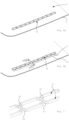
Fig. 3a is a perspective view of a side portion of a panel of the roof panel assembly ofFig. 2 upside down showing an in-coupling element. -
Fig. 3b is a view corresponding to that ofFig. 3a but with LEDs added to the in-coupling element. -
Fig. 3c is an enlarged plan view showing detail III-c inFig. 3b . -
Fig. 4a is a view corresponding to that ofFig. 3a but showing another embodiment. -
Fig. 4b is a view corresponding to that ofFig. 3b but showing the other embodiment. -
Fig. 4c is a view corresponding to that ofFig. 3c but showing the other embodiment. -
Fig. 5a is an enlarged cross-sectional view along the line V-V inFig. 3b showing the panel in an upside-down position. -
Figs. 5b - 5d are views corresponding to that ofFig. 5a but showing further embodiments. -
Figs. 6a and 6b are views corresponding to those ofFigs. 3a and 3b but showing still another embodiment. -
Fig. 7 is an enlarged perspective view of the mould used in the embodiment ofFigs. 6a and 6b . -
Fig. 8a is an enlarged cross-sectional view along the line VIII-VIII inFig. 6b . -
Fig. 8b is a view corresponding to that ofFig. 8a but showing still another embodiment. -
Figs. 9a, 9b are a perspective view and a plan view, respectively, of an in-coupling element and mould according to yet another embodiment. -
Fig. 10 is a view corresponding to that ofFig. 4 but showing yet another embodiment. -
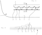
Fig. 11 is a plan view of a portion of a panel showing a part of an in-coupling element and light sources. -
Fig. 12 is an enlarged sectional view along the line XII-XII inFig. 11 . -
Figs. 13a and 13b are views corresponding to those ofFigs. 3a and 3b showing still a further embodiment. -
Fig. 14 is an enlarged cross-sectional view along the line XIV-XIV inFig. 13b . -
Figs. 15a - 15c are views corresponding to that ofFig. 14 showing still other embodiments. -
Fig. 1 shows a part of a vehicle, in this case a passenger car, comprising a glass roof construction. The vehicle comprises aroof opening 1 in afixed roof 2. In this case the open roof construction has a roof panel assembly including twopanels 3, 3' placed adjacent to each other in a longitudinal direction of the vehicle. The frontal of the twopanels 3, 3' is anopenable panel 3 capable of closing and at least partly opening theroof opening 1 of the fixedroof 2. The second panel 3' placed rearward of thefront panel 3 may be a stationary panel closing the remaining part of theroof opening 1, however it is conceivable that also the second panel 3' is a movable panel. Alternatively, it is also conceivable to have just one panel, either fixed or capable of closing and at least partly opening theroof opening 1. -
Figs. 2 and5 show the transparent roof panel assembly and a partial cross-section of amulti-layered panel 3 of the glass roof panel assembly in an upside-down condition. An exterior glass ply 5 (in use the upper ply) and an interior glass ply 6 are attached by aninterlayer 7 and optionally a second interlayer (not shown). For example, theinterlayer 7 may be formed of EVA or PVB. Other materials to form a flexible foil are known and suitable as well as long as the refractive index of theinterlayer 7 is lower than that of the interior glass ply 6 if one wishes to keep any light within the glass ply. For example, glass has a reflective index of 1.52, EVA and PVB of 1.48. - At a lower side of the interior or
first glass ply 6, alight source 8 or series of light-sources 8 is/are provided. InFig. 2 it is shown that the twopanels 3, 3' are provided withlight sources 8 along their whole circumferences. Thelight source 8 may be any light source suitable for coupling light into theinterior glass ply 6. For example, known light sources are LEDs directing light directly into lower side of the interior glass ply 6 or, alternatively or additionally, an elongated, side-emitting light guide arranged next to the lower side of theinterior glass ply 6. - An out-coupling pattern is provided at a surface of the
interior glass ply 6. In particular, the out-coupling pattern is arranged at an interface between the interior glass ply 6 and theinterlayer 7. The interior glass ply 6 and theinterlayer 7 are adjacent to each other, which means they are attached directly to each other or through the outcoupling pattern. Rays of light propagate through the interior glass ply 6 by internal reflection and may impinge on a scattering particle of the out-coupling pattern. Upon impingement, the ray of light is at least partly reflected and reflected light rays are enabled to leave the interior glass ply 6 at an opposite surface of the interior glass ply 6 and is thus emitted into an interior passenger compartment of the vehicle. See for exampleco-pending US application 18/326,346 - Other possibilities for the out-coupling pattern exist. For example, the light may be in-coupled into the
interlayer 7 which includes the out-coupling pattern. The outcoupling pattern may be provided on one of the surfaces of theinterlayer 7, on the interior glass ply 6 or randomly scattered within theinterlayer 7. - The light source 8 (in this case a plurality of LED lights) is coupled to a polyhedron-, e.g., prism- or wedge-shaped, in-
coupling element 9 provided in front of thelight source 8 to in-couple light into the panel from the interior side thereof. The in-coupling element 9 is mainly made from an optical clear glue, such as e.g., Optimax ©, Norland IML 150 or the like. To cure the glue, climate or UV-light may be used, or a two-component glue can be used to activate it. It is preferred to use a glue (or other intermediate means of attachment) that has a refractive index that is close to and preferably higher than that of glass, i.e., 1.52 for an optimal light transmission to theinterior glass ply 6. Due to the glue, the surface of the in-coupling element 9 will adapt exactly to the interior surface of theinterior glass ply 6, as the glue will be provided and supplied to the glass surface in a fluid state. -
Fig. 5a shows that in this embodiment, the in-coupling element is wedge-shaped. Asurface 10 of the wedge-shaped in-coupling element 9 that is facing away from the interior glass ply is inclined to the interior surface of thepanel 3. In order to make such in-coupling element 9 from a fluid adhesive, amould 11 is used at the high side of the wedge-shaped in-coupling element which is the light entering side thereof. In order to mould the in-coupling element 9, thepanel 3 is held at an inclination such that thesurface 10 of the in-coupling element 9 is horizontal. If then adhesive is supplied to the surface of theinterior glass ply 6, it will spread and level out between themould 11 and the inclined interior surface of thepanel 3. If the adhesive is cured immediately after it has levelled locally, it is also possible to form an even in-coupling element along the length of the in-coupling element even if the panel is curved along this length. The supply opening of the adhesive could be held stationary and thepanel 3 is then moved in a 3-D movement along the supply opening. For every in-coupling element around the circumference of thepanel 3, 3', thepanel 3, 3' must be held at a different orientation/inclination and be moved in different directions. -
Figs. 3a - 3c and5a show a first embodiment of the panel assembly. In this embodiment, themould 11 is formed by a permanent strip of optically clear plastic, such as PMMA (polymethylmethacrylate).Fig. 3c shows that the strip hasbends 12 which allow a deformation to compensate for thermal expansion during use of the roof panel assembly.Fig. 3c also showsholes 13 which can be used to position themould 11 with respect to a rig during manufacture, which rig is then used to position themould 11 with respect to thepanel 3. - Between each two bends 12 there is provided a
LED 8, which LEDs are positioned on aPCB strip 14. As is shown inFig. 5a , thePCB strip 14 is attached to the glass ply 6 of thepanel 3 by means of a two-sidedadhesive tape 15 adhering to theglass ply 6 and to thePCB strip 14. - In the embodiment of
Fig. 5b , thetape 15 is extended to a position below themould 11, so that both themould 11 and thePCB strip 14 are attached to theglass ply 6 by means of theadhesive tape 15. - In the embodiment of
Fig. 5c , themould 11 is provided with anextension 16 away from the in-coupling element 9. This extension is used to attach themould 11 to the glass ply 6 of thepanel 3 by means of theadhesive tape 15. ThePCB strip 14 is attached to the surface of the extension facing away from thepanel 3. This surface is inclined to direct the light from the LED or otherlight source 8 towards theinterior glass ply 6.Fig. 5c also shows acapillary stop groove 17 in the surface of themould 11 facing theinterior glass ply 6. Any optical adhesive that is flowing between themould 11 and the surface of the interior glass ply 6 due to capillary forces is stopped at thegroove 17 that is so high that no capillary forces are created there. When themould 11 is made of PMMA material, this has the advantage that it transfers UV light so that if UV light is used to cure the optical adhesive and there is adhesive below themould 11 it will still be cured by the UV light. -
Fig. 5d shows another embodiment where thePCB strip 14 is again attached to theinterior ply 6 of thepanel 3 by means ofadhesive tape 15. The thickness of thistape 15 equals that of theextension 16 of themould 11, whichextension 16 extends up to thetape 15. ThePCB strip 14 is partly fixed to thepanel 3 by means of theadhesive tape 15 and partly extending across theextension 16 of themould 11 and is attached thereto, for example by mushroom-shapedknobs 18 extending throughholes 19 in thePCB strip 14. In this way themould 11 is attached to thepanel 3 by means of thetape 15 indirectly through thePCB strip 14. -
Figs. 4a - 4c shows a variation of the embodiment ofFig. 3 . In this new embodiment, the mould hasextensions 20 at the extreme ends to provide a barrier for the adhesive at the start and end of the in-coupling element 9. The low side of the in-coupling element could also be bordered by a tape which is attached to the panel, either permanently or removable after curing of the optical adhesive.Fig. 4c shows aLED light source 8 and the maximum angle of the light bundle. -
Figs. 6a - 8b show a variation in which the in-coupling element 9 may either have a wedge-shaped cross-section (Fig. 8a ) or a rectangular cross-section (Fig. 8b ). In this embodiment, themould 11 extends completely around the adhesive and consisting more of less of two strip-shapedmoulds 11 from the former embodiments bonded to each other in mirror shape. The two strips are interconnected bybridges 21 which may either extend the full height or leave a gap on their lower sides so that the optical adhesive may flow below thebridges 21 to form one adhesive part. The advantage of theFig. 8a embodiment over that ofFig. 8b is that only half the volume of optical adhesive is required. Optical adhesive is generally very expensive so that minimizing the required amount of adhesive is advantageous. - The embodiment of
Figs. 9a, 9b , themould 11 is provided withhooks 22 to improve the attachment of the optical adhesive to themould 11. In this case, thehooks 22 are positioned on either side of the deformable bends 12 where they do not interfere with the light bundle from the LEDlight source 8. Other positions and shapes of thehooks 22 are conceivable, however. -
Fig. 10 shows an embodiment of themould 11 which is formed withlenses 23, one for eachlight source 8. Thelenses 23 may be formed in one piece with themould 11 and be created during manufacture of themould 11, for example during injection moulding. Thelenses 23 may be either 2D or even 3D to "bundle" the light already in the correct direction (towards the glass at a desired angle) to improve efficiency. An additional reflection lens (not shown) may be provided to reflect light arrays that would otherwise be lost into the correct direction (e.g., parallel to theinclined surface 10 of the in-coupling element 9). Such lens may also be mounted onto thelight source 8, such as the LED. -
Fig. 11 and 12 show an embodiment in which themould 11 is provided with alight guide 24 to guide light from a position spaced from the surface of theinterior ply 6 of thepanel 3 to a position closer thereto. This is particularly useful in case one wishes to use a top emitting LED in which theLED light source 8 emits light perpendicularly to thePCB strip 14. InFig. 12 , thePCB strip 14 is positioned substantially perpendicular to the surface of theply 6 of thepanel 3. However, it would even be possible that the LED light source is emitting light away from thepanel 3. A reflection surface will then be needed to reflect the light in the direction of the (light guide 24 of the) in-coupling element 9. -
Figs. 13a, 13b and 14 show an embodiment in which themould 11 together with the surface of theply 6 of thepanel 3 completely encloses the optical adhesive in order to be able to supply the optical adhesive to the interior surface of thepanel 3 by injection moulding. For this purpose, themould 11 has one or more injection holes 25 (in thiscase 2 at the opposite ends of the mould 11) through which the fluid adhesive is injected into the enclosed space. It is also possible that one of theholes 25 is used to inject fluid adhesive into the space, while theother hole 25 is used for allowing air within the space to escape in case the injection does not take place under vacuum. Other arrangements are possible of course. -
Fig. 15a show a variant in which themould 11 is not permanent but only used during manufacture. For this purpose, themould 11 is made from non-sticking material, such as silicone, and mounted on a rig or the like so that the mould can be removed from thepanel 3 when the adhesive for the in-coupling element 9 has sufficiently cured. After moulding of the in-coupling element 9, thelight source 8 with thePCB strip 14 can be attached to thepanel 3, for example by means of theadhesive tape 15. - In the
Fig. 15b embodiment, thePCB strip 14 with thelight source 8 is attached to thepanel 3 before the mould is positioned and the in-coupling element 9 is formed by moulding the optical adhesive. In this case, the mould 11 (Fig. 15a ) is placed onto thePCB strip 14 at a position next to the LEDlight source 8 so that thelight source 8 is inside the in-coupling element 9. - The embodiment of
Fig. 15c is the extreme embodiment in which the completelight source 8 andPCB strip 14 have been incorporated into the in-coupling element 9. Themould 11 has been placed next to thePCB strip 14 such that the adhesive is poured onto thelight source 8 andPCB strip 14. This embodiment requires more optical adhesive and is therefore not preferred as long as the adhesive is expensive. - It is clear from the above description that the invention provides a roof panel assembly in which the panel is lighted by light sources and in-coupling elements that have favourable characteristics, such as versatility, easy and precise attachment, efficient light transmission, easy assembly and others.
- Detailed embodiments of the present invention are disclosed herein, however, it is to be understood that the disclosed embodiments are merely exemplary of the invention, which can be embodied in various forms. Therefore, specific structural and functional details disclosed herein are not to be interpreted as limiting, but merely as a basis for the claims and as a representative basis for teaching one skilled in the art to variously employ the present invention in expectedly any appropriately detailed structure. In particular, features presented and described in separate dependent claims or in separate embodiments may be applied in combination and any advantageous combination of such claims and embodiments are herewith disclosed.
- Further, the terms and phrases used herein are not intended to be limiting, but rather to provide an understandable description of the invention. The terms "a" or "an", as used herein, are defined as one or more than one. The term plurality, as used herein, is defined as two or more than two. The term another, as used herein, is defined as at least a second or more. The terms including and/or having, as used herein, are defined as comprising (i.e., open language). The term coupled, as used herein, is defined as connected, although not necessarily directly.
- The invention being thus described it is apparent that the same may be varied in many ways. Such variations are not to be regarded as a departure from the spirit and scope of the invention, and all such modifications as would be apparent to one skilled in the art are intended to be included within the scope of the following claims.
- For example, it is possible to replace one or more glass plies in the roof panel assembly by a plastic sheet, for example a polycarbonate sheet. The invention is also useful in panels having only a single ply. Further, the in-coupling element may be partly covered towards the interior of the vehicle by a cover. This cover may also cover the light source with its base. The embodiments shown in the drawing include moulds made of one piece of material. If the mould extends a longer length, it will have flexible portions between sections of the mould. However, it is also conceivable that the mould comprises several sections coupled to each other by couplings. These couplings may be flexible or allow movement.
Claims (15)
- A transparent roof panel assembly for a vehicle roof, the roof panel assembly comprising:• a panel (3) having a transparent area, the panel being configured to be arranged over an opening (1) in the vehicle roof (2) to allow visible light to pass through the transparent area between an exterior of the vehicle and an interior of the vehicle,• at least one light source (8) arranged to provide light in the panel, and• an in-coupling element (9) to in-couple light into the panel from the interior side of the panel, the in-coupling element being attached to the interior side of the panel and redirecting light from the at least one light source (8) into the panel,• wherein the in-coupling element (9) is made at least partly from optical adhesive which is directly moulded to the interior side of the panel, the in-coupling element being bounded at least on its light entering side by a mould (11) for the optical adhesive at least during moulding of the in-coupling element.
- The transparent roof panel assembly of claim 1,
wherein the mould (11) is permanent and forms at least the light entering side of the in-coupling element (9). - The transparent roof panel assembly of claim 2,
wherein the in-coupling element (9) is wedge-shaped with a high side and a low side, wherein the mould (11) is present at least on the high side of the in-coupling element, which is the light-entering side of the in-coupling element. - The transparent roof panel assembly of claim 2 or 3, wherein the mould (11) is in the form of a clear transparent plastic strip and may be one piece of material or coupled segments.
- The transparent roof panel assembly of claim 4,
wherein the clear plastic strip forming the mould (11) is provided with deformable sections (12) along the length of the strip to compensate for thermal expansions during use of the roof panel assembly. - The transparent roof panel assembly of any of claims 2 - 5, wherein the mould (11) is attached to the interior side of the panel (3) with the help of an adhesive tape (15).
- The transparent roof panel assembly according to claim 6, wherein the adhesive tape (15) is positioned on an extension (16) of the mould (11) away from the in-coupling element (9), the extension being used for attaching the at least one light source (8) thereon.
- The transparent roof panel assembly of claim 6, wherein the at least one light source (8) is mounted on a strip (14), such as LED lights on a PCB strip, and the adhesive tape (15) is attached to the strip and to the interior side of the panel (3), whereas the strip (14) holds the mould (11), for example by being clipped to the mould.
- The transparent roof panel assembly of claim 2 or 3, wherein the mould (11) extends all around the in-coupling element (9).
- The transparent roof panel assembly of any of claims 2 - 8, wherein the in-coupling element (9) is bounded on its sides substantially perpendicularly to its light entering side by a barrier (20), such as a piece of tape or by the mould, and/or wherein the mould is provided with hooks (22) extending into the in-coupling element.
- The transparent roof panel assembly of any of claims 2 -10, wherein the mould (11) comprises a lens (23) and the light source (8) is positioned such that light from the light source enters the in-coupling element (9) through the lens.
- The transparent roof panel assembly of any of claims 2 - 11, wherein the mould (11) is provided with a light guiding element (24) to guide light from a position at a distance from the interior side of the panel (3) to a position closer to the interior side of the panel where the light enters the in-coupling element (9).
- The transparent roof panel assembly of claim 2,
wherein the mould (11) covers the in-coupling element (9) completely and the in-coupling element is formed by injection moulding of the optical adhesive. - The transparent roof panel assembly of claim 1, wherein a retractable tool of non-sticking material forms the mould (11) for the in-coupling element (9) during moulding of the optical adhesive, and wherein the light source (8) is preferably at least partly moulded within the in-coupling element.
- A method of attaching a transparent light transmitting element, such as an in-coupling element (9), to a ply (6) of a transparent roof panel, comprising the steps of:providing a mould (11),holding the mould with respect to the ply,positioning the panel (3) such that the surface (10) of the in-coupling element (9) to be formed, which is turned away from glass ply, is horizontal,moulding fluid optical adhesive onto the glass ply (6) next to the mould (11) such that it takes the shape of the in-coupling element to be formed and adheres to the glass ply (6), and optionally to the mould if that is an optically clear permanent mould,allowing or forcing the optical adhesive to cure.
Priority Applications (6)
| Application Number | Priority Date | Filing Date | Title |
|---|---|---|---|
| EP23177936.4A EP4474694A1 (en) | 2023-06-07 | 2023-06-07 | A transparent roof panel assembly for a vehicle roof, and method of making it |
| DE202023105972.4U DE202023105972U1 (en) | 2023-06-07 | 2023-10-16 | Transparent roof panel device for a vehicle roof |
| KR1020240068416A KR20240174038A (en) | 2023-06-07 | 2024-05-27 | A transparent roof panel assembly for a vehicle roof, and method of making it |
| CN202421244932.6U CN222496195U (en) | 2023-06-07 | 2024-06-03 | Transparent roof panel assembly for vehicle roof |
| CN202410706214.4A CN119099479A (en) | 2023-06-07 | 2024-06-03 | Transparent roof panel assembly for vehicle roof and method of manufacturing the same |
| US18/733,398 US20240409027A1 (en) | 2023-06-07 | 2024-06-04 | Transparent roof panel assembly for a vehicle roof, and method of making it |
Applications Claiming Priority (1)
| Application Number | Priority Date | Filing Date | Title |
|---|---|---|---|
| EP23177936.4A EP4474694A1 (en) | 2023-06-07 | 2023-06-07 | A transparent roof panel assembly for a vehicle roof, and method of making it |
Publications (1)
| Publication Number | Publication Date |
|---|---|
| EP4474694A1 true EP4474694A1 (en) | 2024-12-11 |
Family
ID=86732316
Family Applications (1)
| Application Number | Title | Priority Date | Filing Date |
|---|---|---|---|
| EP23177936.4A Pending EP4474694A1 (en) | 2023-06-07 | 2023-06-07 | A transparent roof panel assembly for a vehicle roof, and method of making it |
Country Status (5)
| Country | Link |
|---|---|
| US (1) | US20240409027A1 (en) |
| EP (1) | EP4474694A1 (en) |
| KR (1) | KR20240174038A (en) |
| CN (2) | CN222496195U (en) |
| DE (1) | DE202023105972U1 (en) |
Citations (5)
| Publication number | Priority date | Publication date | Assignee | Title |
|---|---|---|---|---|
| US5876107A (en) * | 1995-06-27 | 1999-03-02 | Lumitex, Inc. | Light emitting panel assemblies |
| EP1791010A2 (en) * | 2005-11-24 | 2007-05-30 | TPO Hong Kong Holding Limited | Light-emitting unit and method of producing the same |
| US20130213929A1 (en) * | 2012-02-17 | 2013-08-22 | 3M Innovative Properties Company | Method of forming a lighting system |
| WO2021198262A1 (en) | 2020-04-03 | 2021-10-07 | Webasto SE | Vehicle window having a light source and a light-conducting layer |
| WO2023156939A1 (en) * | 2022-02-16 | 2023-08-24 | Agp Worldwide Operations Gmbh | Glazing having total internal reflection through improved light injection |
-
2023
- 2023-06-07 EP EP23177936.4A patent/EP4474694A1/en active Pending
- 2023-10-16 DE DE202023105972.4U patent/DE202023105972U1/en active Active
-
2024
- 2024-05-27 KR KR1020240068416A patent/KR20240174038A/en active Pending
- 2024-06-03 CN CN202421244932.6U patent/CN222496195U/en active Active
- 2024-06-03 CN CN202410706214.4A patent/CN119099479A/en active Pending
- 2024-06-04 US US18/733,398 patent/US20240409027A1/en active Pending
Patent Citations (5)
| Publication number | Priority date | Publication date | Assignee | Title |
|---|---|---|---|---|
| US5876107A (en) * | 1995-06-27 | 1999-03-02 | Lumitex, Inc. | Light emitting panel assemblies |
| EP1791010A2 (en) * | 2005-11-24 | 2007-05-30 | TPO Hong Kong Holding Limited | Light-emitting unit and method of producing the same |
| US20130213929A1 (en) * | 2012-02-17 | 2013-08-22 | 3M Innovative Properties Company | Method of forming a lighting system |
| WO2021198262A1 (en) | 2020-04-03 | 2021-10-07 | Webasto SE | Vehicle window having a light source and a light-conducting layer |
| WO2023156939A1 (en) * | 2022-02-16 | 2023-08-24 | Agp Worldwide Operations Gmbh | Glazing having total internal reflection through improved light injection |
Also Published As
| Publication number | Publication date |
|---|---|
| DE202023105972U1 (en) | 2024-01-20 |
| CN119099479A (en) | 2024-12-10 |
| KR20240174038A (en) | 2024-12-16 |
| US20240409027A1 (en) | 2024-12-12 |
| CN222496195U (en) | 2025-02-18 |
Similar Documents
| Publication | Publication Date | Title |
|---|---|---|
| US12286056B2 (en) | Vehicle window pane comprising a light source and a light-conducting layer | |
| US12233778B2 (en) | Transparent roof panel assembly for a vehicle roof | |
| CN100468101C (en) | Light guiding device and method of guiding light | |
| EP2548769A1 (en) | Automotive rear light | |
| CN208846346U (en) | Lamp group part and motor vehicles for motor vehicles | |
| US12503046B2 (en) | Vehicle pane with a lighting device | |
| CN110099794B (en) | Windshield assembly with lighting device | |
| JP2010534158A (en) | Rear element for cars with lighting units | |
| US10589666B2 (en) | Open roof construction for a vehicle | |
| CN120112419A (en) | Vehicle window panel with light source and light conductor layer | |
| US20240409027A1 (en) | Transparent roof panel assembly for a vehicle roof, and method of making it | |
| US20240272273A1 (en) | Exterior Component for a Means of Transportation, Means of Transportation, and Method for Producing an Exterior Component | |
| JP2024538287A (en) | Optical module for a light-emitting device in an automotive vehicle | |
| US12344163B2 (en) | Vehicle window with lighting unit | |
| US11674661B2 (en) | Method for manufacturing light guiding plate, light guiding plate, and lighting tool for vehicle | |
| CN100416315C (en) | Light guide system with sheet-like light-emitting elements | |
| JP7208205B2 (en) | Display device and display device manufacturing method | |
| JP2007505336A (en) | Light guide system having a plate-like triangular guide member | |
| JP2022087071A (en) | Automotive lighting and/or signaling device with external decorative element, and related assembly method | |
| US20260054641A1 (en) | Glazing having a light injection assembly | |
| JP2025539517A (en) | Light incidence structure, vehicle window, vehicle window panel, vehicle window panel assembly, and vehicle | |
| CN119947927A (en) | Vehicle lighting device configured to perform the function of a high mounted stop lamp | |
| KR20160093148A (en) | Edge type turn signal lamp of outside mirror applying extruded light guide plate | |
| HK1140731A (en) | Rear element for a motor vehicle comprising a lighting unit |
Legal Events
| Date | Code | Title | Description |
|---|---|---|---|
| PUAI | Public reference made under article 153(3) epc to a published international application that has entered the european phase |
Free format text: ORIGINAL CODE: 0009012 |
|
| STAA | Information on the status of an ep patent application or granted ep patent |
Free format text: STATUS: THE APPLICATION HAS BEEN PUBLISHED |
|
| AK | Designated contracting states |
Kind code of ref document: A1 Designated state(s): AL AT BE BG CH CY CZ DE DK EE ES FI FR GB GR HR HU IE IS IT LI LT LU LV MC ME MK MT NL NO PL PT RO RS SE SI SK SM TR |
|
| STAA | Information on the status of an ep patent application or granted ep patent |
Free format text: STATUS: REQUEST FOR EXAMINATION WAS MADE |
|
| 17P | Request for examination filed |
Effective date: 20250611 |