EP4474688A1 - Clamp ring for fastening pipes - Google Patents
Clamp ring for fastening pipes Download PDFInfo
- Publication number
- EP4474688A1 EP4474688A1 EP24315242.8A EP24315242A EP4474688A1 EP 4474688 A1 EP4474688 A1 EP 4474688A1 EP 24315242 A EP24315242 A EP 24315242A EP 4474688 A1 EP4474688 A1 EP 4474688A1
- Authority
- EP
- European Patent Office
- Prior art keywords
- strap
- clamp ring
- clip
- lever
- hook
- Prior art date
- Legal status (The legal status is an assumption and is not a legal conclusion. Google has not performed a legal analysis and makes no representation as to the accuracy of the status listed.)
- Pending
Links
Images





Classifications
-
- F—MECHANICAL ENGINEERING; LIGHTING; HEATING; WEAPONS; BLASTING
- F16—ENGINEERING ELEMENTS AND UNITS; GENERAL MEASURES FOR PRODUCING AND MAINTAINING EFFECTIVE FUNCTIONING OF MACHINES OR INSTALLATIONS; THERMAL INSULATION IN GENERAL
- F16L—PIPES; JOINTS OR FITTINGS FOR PIPES; SUPPORTS FOR PIPES, CABLES OR PROTECTIVE TUBING; MEANS FOR THERMAL INSULATION IN GENERAL
- F16L33/00—Arrangements for connecting hoses to rigid members; Rigid hose-connectors, i.e. single members engaging both hoses
- F16L33/02—Hose-clips
- F16L33/12—Hose-clips with a pivoted or swinging tightening or securing member, e.g. toggle lever
-
- F—MECHANICAL ENGINEERING; LIGHTING; HEATING; WEAPONS; BLASTING
- F16—ENGINEERING ELEMENTS AND UNITS; GENERAL MEASURES FOR PRODUCING AND MAINTAINING EFFECTIVE FUNCTIONING OF MACHINES OR INSTALLATIONS; THERMAL INSULATION IN GENERAL
- F16L—PIPES; JOINTS OR FITTINGS FOR PIPES; SUPPORTS FOR PIPES, CABLES OR PROTECTIVE TUBING; MEANS FOR THERMAL INSULATION IN GENERAL
- F16L19/00—Joints in which sealing surfaces are pressed together by means of a member, e.g. a swivel nut, screwed on, or into, one of the joint parts
- F16L19/06—Joints in which sealing surfaces are pressed together by means of a member, e.g. a swivel nut, screwed on, or into, one of the joint parts in which radial clamping is obtained by wedging action on non-deformed pipe ends
-
- F—MECHANICAL ENGINEERING; LIGHTING; HEATING; WEAPONS; BLASTING
- F16—ENGINEERING ELEMENTS AND UNITS; GENERAL MEASURES FOR PRODUCING AND MAINTAINING EFFECTIVE FUNCTIONING OF MACHINES OR INSTALLATIONS; THERMAL INSULATION IN GENERAL
- F16L—PIPES; JOINTS OR FITTINGS FOR PIPES; SUPPORTS FOR PIPES, CABLES OR PROTECTIVE TUBING; MEANS FOR THERMAL INSULATION IN GENERAL
- F16L21/00—Joints with sleeve or socket
- F16L21/08—Joints with sleeve or socket with additional locking means
-
- F—MECHANICAL ENGINEERING; LIGHTING; HEATING; WEAPONS; BLASTING
- F16—ENGINEERING ELEMENTS AND UNITS; GENERAL MEASURES FOR PRODUCING AND MAINTAINING EFFECTIVE FUNCTIONING OF MACHINES OR INSTALLATIONS; THERMAL INSULATION IN GENERAL
- F16L—PIPES; JOINTS OR FITTINGS FOR PIPES; SUPPORTS FOR PIPES, CABLES OR PROTECTIVE TUBING; MEANS FOR THERMAL INSULATION IN GENERAL
- F16L25/00—Construction or details of pipe joints not provided for in, or of interest apart from, groups F16L13/00 - F16L23/00
- F16L25/14—Joints for pipes of different diameters or cross-section
-
- F—MECHANICAL ENGINEERING; LIGHTING; HEATING; WEAPONS; BLASTING
- F16—ENGINEERING ELEMENTS AND UNITS; GENERAL MEASURES FOR PRODUCING AND MAINTAINING EFFECTIVE FUNCTIONING OF MACHINES OR INSTALLATIONS; THERMAL INSULATION IN GENERAL
- F16L—PIPES; JOINTS OR FITTINGS FOR PIPES; SUPPORTS FOR PIPES, CABLES OR PROTECTIVE TUBING; MEANS FOR THERMAL INSULATION IN GENERAL
- F16L21/00—Joints with sleeve or socket
- F16L21/002—Sleeves or nipples for pipes of the same diameter; Reduction pieces
Definitions
- Heating, ventilation and air-conditioning systems require the interconnection of multiple pipes. This can be time-consuming and difficult, as such systems are normally installed in confined spaces.
- the strap comprises an inner strand and an outer strand connected at opposite ends, the outer strand being longer than the inner strand.
- the provision of multiple strands enables the clamp ring to accommodate varying pipe diameters. As the inner strand is shorter, it can adapt to pipes with circumferences that are relatively smaller than the ones that can be accommodated by the outer strand.
- the inner strand can distend, stretch or otherwise deform to adapt to pipes with larger circumferences, up to pipes with circumferences that match the length of the outer strand.
- At least one notch in the clamp ring is concave.
- At least one matching notch is arranged on each of the outer strand and inner strand.
- at least one concave notch is paired with at least one convex notch.
- the strap comprises a latch arranged to stop the lever from moving, when the clamp ring is placed in a closed position.
- the locking movement of the lever is advantageous to prevent the clamp ring from being accidentally opened by impacts or vibrations.
- a first breakaway connector is provided at a first pivot point between the strap and the lever, and a second breakaway connector is provided at a second pivot point between the lever and the clip.
- the clip comprises a hook designed to engage with a hook on the strap to grip the strap.
- the clip hook and the strap hook each comprise a radial or circumferential pitch to inhibit lateral movement between the clip and the strap.
- the clip hook and the strap hook each comprise a pair of hook portions that are radially and/or circumferentially displaced from one another, so as to provide the radial or circumferential pitch.
- the clip hook comprises a reinforcement ridge along at least part of its length.
- the clip hook comprises a lateral reinforcement ridge perpendicular to the reinforcement ridge over at least part of its length.
- the strap comprises a ridge protruding from its inner surface over at least part of its length to engage onto the outer surface of a pipe to which the clamp ring is fastened.
- the strap comprises a tongue arranged to guide and/or hold the clip and optionally wherein the tongue comprises a guide wall and further optionally or alternatively, the tongue comprises a ramp.
- the strap comprises one or more links connecting the inner strand to the outer strand.
- connection is intended to include direct connections between two elements without the interposition of other elements between them, as well as indirect connections between elements in which one or more other elements are interposed between them.
- This terminology includes the words specifically mentioned above, their derivatives, and words with a similar meaning.
- the part enables a tube or a pipe with pressure distributed over the entire circumference to be secured.
- the part consists of a retaining piece that comprises a strap, a tensioning lever piece and a clip piece. These three components are injected in a single operation, using small connectors that can be broken off when locked onto the tube to be secured.
- This tensioning lever device enables high clamping force to be achieved due to the movements between the various components around their rotational axes.
- the retaining portion can accommodate several notches to adjust the clamping force.
- the strap portion in contact with the tube to be secured, offers the advantage of being flexible and of conforming to the shape of a tube that may be slightly deformed.
- a small locking clip attached to the retaining portion prevents accidental opening of the tensioning lever. Exemplary application: heating, ventilation and/or air-conditioning systems for motor vehicles.
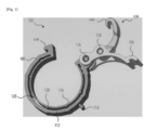
- Figure 1 shows a perspective view of a clamp ring 102 in the open position.
- the clamp ring 102 comprises a strap 104, a lever 106 and a clip 108 that are connected to each other.
- the strap 104 is connected to the lever 106 via a first pivot point 116.
- the lever 106 is then itself connected to the clip 108 by a second pivot point 118.
- the strap 104, the lever 106 and the clip 108 can rotate relative to each other around the first pivot point 116 and the second pivot point 118.
- first pivot point 116 and the second pivot point 118 can be provided with supporting areas, meaning an additional body of material, which is arranged to come into contact with the lever 106 when the clip 102 is moved from an open position to a closed position.
- the strap 104 is made of an inner strand 110 and of an outer strand 112, connected at respective ends.
- the strap 104 has a substantially open circular shape. Due to its substantially circular shape, the outer strand 112 is necessarily longer than the inner strand 110, with both strands generally taking a circular path.
- the circular path taken by the inner strand 110 is smaller in diameter than the circular path taken by the outer strand 112.
- the strap 104 (and accordingly the inner strand 110 and the outer strand 112) is made of an elastic material, such as metal or plastic, and is capable of bending or deforming to bring respective ends from a separated position to a relatively close position, forming a closed circle.
- the strap 104 further comprises a latch 114, shown located on the outer strand 112, although obviously other suitable locations are possible for a latch 114 on the clamp ring 102.
- the purpose of the latch is to stop the movement of the lever 106 when the clamp ring 102 is in the closed position, so the latch 114 can be placed anywhere on the clamp ring 102 that enables this function to be achieved.
- the inner strand 110 and the outer strand 112 comprise notches 120.
- the notches 120 are arranged on opposite sides of the inner strand 110 and of the outer strand 112 so that the notches 120 of one strand interfere or otherwise interact with the other strand, or the notches 120 of the other strand. These notches enable both strands to provide a support function, regardless of whether or not the pipe inserted into the clamp ring 102 has a circumference comparable to the outer strand 112.
- At least the inner strand 110 is capable of distending or otherwise deforming to accommodate a range of pipe circumferences, which enables the clamp ring 102 to couple effectively to a pipe with a reduced manufacturing tolerance or to a deformed pipe.
- the clip 108 is provided with gripping means, such as a hook, with which it can grip one end of the strap 104, for example via a matching recess, so that the clip 108 can push, under the action of the lever 106, one end of the strap 104 towards the other end.
- the clip 108 comprises a hook 180 designed to engage with a hook 140 on the strap .104 to grip the strap 104.
- the lever 106 is arranged between the clip 108 and the strap 104, connecting and joining the parts, via a first pivot point 116 and a second pivot point 118.
- the lever 106 provides a means, via the clip 108, of pushing the ends of the strap 104 together and placing the clamp ring 102 in the closed position.
- the latch 114 can be reversible, with one possible embodiment consisting in providing a ratchet on the outer strand 112 and a matching tooth on the lever 106, as shown in Figure 1 .
- the latch 114 can be released by releasing the ratchet tooth, and the clamp ring 102 can be returned to the open position, thus enabling the maintenance of a pipe connected using the clamp ring 102.
- Figure 2 shows the clamp ring 102 in Figure 1 in the closed position.
- the clip 108 grips the strap 104 and the respective ends of the strap 104 are pulled alongside each other so that the strap 104 forms a generally closed circle.
- the lever 106 is placed in a locked position with the latch 114 engaged.
- Figure 3 is a close-up view of the first pivot point 116 and of the second pivot point 118 located between the strap 104, the lever 106 and the clip 108 on the clamp ring 102.
- Breakaway connectors 312 are present between the strap 104, the lever 106 and the clip 108 at the first pivot point 116 and the second pivot point 118.
- Such breakaway connectors 312 allow the clamp ring 102 to be made in a single manufacturing step, for example by casting or injection molding.
- the breakaway connectors 312 form a passage through which the material can flow from one part to the other, ensuring the formation of a complete clamp ring 102 during the single manufacturing step.
- breakaway connector 312 can be provided between each point, even if the number of breakaway connectors 312 is limited by the need for a user to be able to manually break the breakaway connectors 312. Too many breakaway connectors 312 can prevent a user from being able to operate the clamp ring 102 or require a tool, which would impair its ease of use and/or the speed with which it can be operated. Three breakaway connectors 312 are shown in Figure 3 at each pivot point by way of example.
- the breakaway connectors 312 can comprise a tapered section, comprising less material, which makes them easier to break.
- breakaway connectors 312 can be located at any point between the strap 104, the lever 106 and the clip 108, provided that the breakaway connectors 312 can perform their function as a channel through which the material can flow, enabling the formation of a complete clamp ring 102 in a single manufacturing step.
- Figure 4 shows a cross-section through a pivot point of the clamp ring 102.
- the parts can be either the lever 106 and the strap 104 or the lever 106 and the clip 108. This is irrelevant, as the function described herein will be the same for all parts.
- a breakaway connector 312 is shown in cross-section spanning the gap between the parts of the clamp ring 102 at the first pivot point 116.
- the thickness of the breakaway connector 312 is reduced compared to the thickness of the parts to which it is connected.
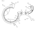
- FIGS 5 to 7 show a clamp ring 202 according to another example similar to the clamp ring 102 in Figures 1 to 4 , where similar references represent similar features, incremented by 100.
- the clamp ring 202 according to this example differs from the one in Figures 1 to 4 in that the hook 280 of the clip 208 and the hook 240 of the strap 204 each comprise a radial or circumferential pitch 281, 241 to inhibit lateral movement between the clip 208 and the strap 204.
- the hook 280 of the clip 208 and the hook 240 of the strap 204 each comprise a pair of hook portions 282, 283, 242, 243 displaced radially and/or circumferentially relative to each other, so as to provide the radial or circumferential pitch 281, 241.
- the hook 280 of the clip 108 also comprises a reinforcement ridge 284 over at least part of its length and a lateral reinforcement ridge 285 perpendicular to the reinforcement ridge 284 over at least part of its length.
- the strap 204 also comprises a ridge 244 protruding from its inner surface 245 over at least part of its length to engage onto the outer surface of a pipe to which the clamp ring is fastened.
- the lever 206 also comprises inner ridges 260 to reduce gaps and lateral movements while the clamp ring 202 is being closed and when it is closed. It makes the whole part more stable.
- FIG 8 shows a clamp ring 302 according to another example similar to the clamp rings 102 and 202 in Figures 1 to 7 , where similar references represent similar features.
- the clamp ring 302 further comprises a tongue 391 attached to the outer strand 112 and arranged such that a tip of the tongue 391 is adjacent the strap hook 140.
- the purposes of the tongue 391 are to act as a guide for the clip 108, to ensure the clip correctly travels towards and engages with the strap hook 140, and also to hold the clip 108 in connection with the strap hook 140, for example, when the clamp ring 302, is in transit, thereby maintaining the clamp ring 302 in a semi-closed position.
- the breakaway connectors 312 may be omitted.
- the tongue 391 means that the clamp ring 302 may be fitted single-handedly as the tongue 391 guides the clip 108 into correct placement.
- This effect is further enhanced by providing an optional side wall 394 or walls to the tongue to ensure correct lateral positioning of the clip 108 and/or an optional ramp 393 to ensure the tongue 391 captures the clip 108 easily.
- lateral means movement in a direction substantially perpendicular, or at least not parallel with a direction of intended movement of the clip 108 (i.e. towards and away from the strap hook 104).
- the tongue 391 is formed of resilient material, such that once the clip 108 is captured by the tongue 391, the clip is urged by the tongue towards the clamp ring 302.
- One or more links 392 are also optionally added between the outer stand 112 and inner strand 119.
- the links connect the strands at locations intermediate connected ends (see discussion above) in order to improve the rigidity of the whole clamp ring 302. Increased rigidity helps both with the assembly and the holding of the collar by an end user.
- the one or more links 392 can also prevent plastic deformation of the clamp ring 302 when placing the clamp ring 302 in a closed position.
Landscapes
- Engineering & Computer Science (AREA)
- General Engineering & Computer Science (AREA)
- Mechanical Engineering (AREA)
- Clamps And Clips (AREA)
Abstract
The invention relates to a clamp ring (102) for fastening a pipe, the clamp ring comprising a strap (104), a lever (106) and a clip (108). The strap (104) is attached to the lever (106), and the lever (106) is attached to the clip (108), the clip (108) being arranged to grip the strap (104), and, with the lever (106) gripping the strap (104), the lever (106) being arranged to push the opposite ends of the strap (104) towards each other. The clamp ring (102) is made in a single piece, the strap (104), the lever (106) and the clip (108) being connected to each other by breakaway connectors that break when the strap, the lever and the clip are moved relative to each other.
Description
- The invention relates to a clamp ring for fastening a pipe.
- Heating, ventilation and air-conditioning systems require the interconnection of multiple pipes. This can be time-consuming and difficult, as such systems are normally installed in confined spaces.
- Another problem arises when the pipes are not perfectly cylindrical or manufacturing tolerances are broad, which results in minor variations that an installer needs to take into account.
- Pipe fasteners can be complex, multi-part fittings that are challenging to handle. A system can require a large number of such fasteners, which are costly to manufacture due to their multiple separate parts.
- According to a first exemplary embodiment of the present invention, a clamp ring for fastening a pipe is provided, the clamp ring comprising a strap, a lever, and a clip, in which the strap is attached to the lever, and the lever is attached to the clip, the clip being arranged to grip the strap, and, with the lever gripping the strap, the lever being arranged to push opposite ends of the strap towards each other; in which the clamp ring is made from a single piece, the strap, lever and clip being connected to each other by breakaway connectors that break when the strap, lever and clip are moved relative to each other. Making the pipe fastener from a single piece considerably reduces production costs, since multiple separate processes are made redundant. Moreover, there is no risk of the parts of the pipe fastener coming apart in transit and time is saved since a user of the fastener does not need to assemble the pipe fastener or prepare it for use. Appropriately, the strap comprises an inner strand and an outer strand connected at opposite ends, the outer strand being longer than the inner strand. The provision of multiple strands enables the clamp ring to accommodate varying pipe diameters. As the inner strand is shorter, it can adapt to pipes with circumferences that are relatively smaller than the ones that can be accommodated by the outer strand.
- The inner strand can distend, stretch or otherwise deform to adapt to pipes with larger circumferences, up to pipes with circumferences that match the length of the outer strand.
- Preferably, the inner strand and/or the outer strand comprise one or more notches between the inner strand and the outer strand. The notches can be convex or concave. Matching notches can be arranged on each of the outer strand and inner strand. A concave notch can be paired with a convex notch. The notches provide additional material between the strands, so that if a pipe with a circumference smaller than the length of the outer strand is placed in the clamp ring, and the clamp ring is placed in a closed position, the notches of one strand come into contact with the opposite strand or opposite notches, which enables the opposite strands to provide additional structural support and to avoid part redundancy.
- Preferentially, at least one notch in the clamp ring is convex.
- Preferentially, at least one notch in the clamp ring is concave.
- Preferentially, at least one matching notch is arranged on each of the outer strand and inner strand. Preferentially, at least one concave notch is paired with at least one convex notch.
- Appropriately, the strap comprises a latch arranged to stop the lever from moving, when the clamp ring is placed in a closed position. When the clamp ring is in the closed position, the locking movement of the lever is advantageous to prevent the clamp ring from being accidentally opened by impacts or vibrations. Preferably, a first breakaway connector is provided at a first pivot point between the strap and the lever, and a second breakaway connector is provided at a second pivot point between the lever and the clip.
- If a user must, of necessity, rotate the lever, clip and straps around the pivot points to adjust the clamp ring, this arrangement of the breakaway connectors ensures that no additional operation by the user is required to break the breakaway connectors.
- Preferentially, the clip comprises a hook designed to engage with a hook on the strap to grip the strap. Preferentially, the clip hook and the strap hook each comprise a radial or circumferential pitch to inhibit lateral movement between the clip and the strap.
- Preferentially, the clip hook and the strap hook each comprise a pair of hook portions that are radially and/or circumferentially displaced from one another, so as to provide the radial or circumferential pitch. Preferentially, the clip hook comprises a reinforcement ridge along at least part of its length.
- Preferentially, the clip hook comprises a lateral reinforcement ridge perpendicular to the reinforcement ridge over at least part of its length.
- Preferentially, the strap comprises a ridge protruding from its inner surface over at least part of its length to engage onto the outer surface of a pipe to which the clamp ring is fastened.
- Appropriately, the strap comprises a tongue arranged to guide and/or hold the clip and optionally wherein the tongue comprises a guide wall and further optionally or alternatively, the tongue comprises a ramp. Preferentially, the strap comprises one or more links connecting the inner strand to the outer strand.
- Embodiments of the invention will now be described, by way of example only, with reference to the accompanying drawings.
- [
Fig. 1 ] illustrates a clamp ring according to at least one embodiment of the invention, in the open position; - [
Fig. 2 ] illustrates a clamp ring according to at least one embodiment of the invention, in the closed position; - [
Fig. 3 ] shows a close-up view of a part in a clamp ring according to at least one embodiment of the invention; - [
Fig. 4 ] shows a cross-section of a clamp ring according to at least one embodiment of the invention; - [
Fig. 5 ] shows a clamp ring according to at least one embodiment of the invention, in the open position; - [
Fig. 6 ] shows a clamp ring according to at least one embodiment of the invention, in the open position; - [
Fig. 7 ] illustrates a clamp ring according to at least one embodiment of the invention, in the closed position; and - [
Fig. 8 ] shows A. a clamp ring according to at least one embodiment of the invention, in the open position, B. a clamp ring according to at least one embodiment of the invention, in a semi-closed position, and C. a clamp ring according to at least one embodiment of the invention, in the closed position. - A number of terms are used in the following description, for convenience and without being limiting. The words "right", "left", "lower", "upper", "front", "rear", "upwards", "down" and "downwards" refer to directions on the drawings to which reference is made and relate to the component described when assembled and mounted. The words "inner", "inward", "outer" and "outward" refer to directions towards and away from, respectively, a designated centerline or a geometric center of an element being described (for example the central axis), the specific meaning being readily apparent from the context of the description.
- Additionally, as used herein, the terms "connected", "attached", "coupled" and "mounted" are intended to include direct connections between two elements without the interposition of other elements between them, as well as indirect connections between elements in which one or more other elements are interposed between them. This terminology includes the words specifically mentioned above, their derivatives, and words with a similar meaning.
- Additionally, unless otherwise specified, the use of ordinal adjectives, such as "first", "second" and "third" etc., merely indicates that reference is being made to different instances of similar objects without implying that the objects so described must be in a given sequence, in time, in space, in a ranking or in any other way. Identical reference numbers are used to represent identical features throughout the document.
- A part enabling a tube or a pipe with pressure distributed over the entire circumference to be secured.
- The part enables a tube or a pipe with pressure distributed over the entire circumference to be secured. The part consists of a retaining piece that comprises a strap, a tensioning lever piece and a clip piece. These three components are injected in a single operation, using small connectors that can be broken off when locked onto the tube to be secured. This tensioning lever device enables high clamping force to be achieved due to the movements between the various components around their rotational axes. The retaining portion can accommodate several notches to adjust the clamping force. The strap portion, in contact with the tube to be secured, offers the advantage of being flexible and of conforming to the shape of a tube that may be slightly deformed. A small locking clip attached to the retaining portion prevents accidental opening of the tensioning lever. Exemplary application: heating, ventilation and/or air-conditioning systems for motor vehicles.
-
Figure 1 shows a perspective view of aclamp ring 102 in the open position. Theclamp ring 102 comprises astrap 104, alever 106 and aclip 108 that are connected to each other. Thestrap 104 is connected to thelever 106 via afirst pivot point 116. Thelever 106 is then itself connected to theclip 108 by asecond pivot point 118. Thestrap 104, thelever 106 and theclip 108 can rotate relative to each other around thefirst pivot point 116 and thesecond pivot point 118. - One or both of the
first pivot point 116 and thesecond pivot point 118 can be provided with supporting areas, meaning an additional body of material, which is arranged to come into contact with thelever 106 when theclip 102 is moved from an open position to a closed position. - The
strap 104 is made of aninner strand 110 and of anouter strand 112, connected at respective ends. Thestrap 104 has a substantially open circular shape. Due to its substantially circular shape, theouter strand 112 is necessarily longer than theinner strand 110, with both strands generally taking a circular path. The circular path taken by theinner strand 110 is smaller in diameter than the circular path taken by theouter strand 112. The strap 104 (and accordingly theinner strand 110 and the outer strand 112) is made of an elastic material, such as metal or plastic, and is capable of bending or deforming to bring respective ends from a separated position to a relatively close position, forming a closed circle. - The
strap 104 further comprises alatch 114, shown located on theouter strand 112, although obviously other suitable locations are possible for alatch 114 on theclamp ring 102. The purpose of the latch is to stop the movement of thelever 106 when theclamp ring 102 is in the closed position, so thelatch 114 can be placed anywhere on theclamp ring 102 that enables this function to be achieved. - The
inner strand 110 and theouter strand 112 comprisenotches 120. Thenotches 120 are arranged on opposite sides of theinner strand 110 and of theouter strand 112 so that thenotches 120 of one strand interfere or otherwise interact with the other strand, or thenotches 120 of the other strand. These notches enable both strands to provide a support function, regardless of whether or not the pipe inserted into theclamp ring 102 has a circumference comparable to theouter strand 112. - Preferably, at least the
inner strand 110 is capable of distending or otherwise deforming to accommodate a range of pipe circumferences, which enables theclamp ring 102 to couple effectively to a pipe with a reduced manufacturing tolerance or to a deformed pipe. - The
clip 108 is provided with gripping means, such as a hook, with which it can grip one end of thestrap 104, for example via a matching recess, so that theclip 108 can push, under the action of thelever 106, one end of thestrap 104 towards the other end. In this example, theclip 108 comprises ahook 180 designed to engage with ahook 140 on the strap .104 to grip thestrap 104. - The
lever 106 is arranged between theclip 108 and thestrap 104, connecting and joining the parts, via afirst pivot point 116 and asecond pivot point 118. Thelever 106 provides a means, via theclip 108, of pushing the ends of thestrap 104 together and placing theclamp ring 102 in the closed position. - Once in the closed position, the lever can be stopped by the
latch 114. Thelatch 114 can be reversible, with one possible embodiment consisting in providing a ratchet on theouter strand 112 and a matching tooth on thelever 106, as shown inFigure 1 . Thelatch 114 can be released by releasing the ratchet tooth, and theclamp ring 102 can be returned to the open position, thus enabling the maintenance of a pipe connected using theclamp ring 102. -
Figure 2 shows theclamp ring 102 inFigure 1 in the closed position. Theclip 108 grips thestrap 104 and the respective ends of thestrap 104 are pulled alongside each other so that thestrap 104 forms a generally closed circle. Thelever 106 is placed in a locked position with thelatch 114 engaged. -
Figure 3 is a close-up view of thefirst pivot point 116 and of thesecond pivot point 118 located between thestrap 104, thelever 106 and theclip 108 on theclamp ring 102.Breakaway connectors 312 are present between thestrap 104, thelever 106 and theclip 108 at thefirst pivot point 116 and thesecond pivot point 118.Such breakaway connectors 312 allow theclamp ring 102 to be made in a single manufacturing step, for example by casting or injection molding. Thebreakaway connectors 312 form a passage through which the material can flow from one part to the other, ensuring the formation of acomplete clamp ring 102 during the single manufacturing step. - It is understood that more than one
breakaway connector 312 can be provided between each point, even if the number ofbreakaway connectors 312 is limited by the need for a user to be able to manually break thebreakaway connectors 312. Too manybreakaway connectors 312 can prevent a user from being able to operate theclamp ring 102 or require a tool, which would impair its ease of use and/or the speed with which it can be operated. Threebreakaway connectors 312 are shown inFigure 3 at each pivot point by way of example. - To make them easier to break, the
breakaway connectors 312 can comprise a tapered section, comprising less material, which makes them easier to break. - It is understood that the
breakaway connectors 312 can be located at any point between thestrap 104, thelever 106 and theclip 108, provided that thebreakaway connectors 312 can perform their function as a channel through which the material can flow, enabling the formation of acomplete clamp ring 102 in a single manufacturing step. - In
Figure 3 , thebreakaway connectors 312 are shown at thefirst pivot point 116 and thesecond pivot point 118, since a user has to rotate these parts relative to each other during normal use of theclamp ring 102, which means that no special action, rotation or manipulation is required by the user to break thebreakaway connectors 312. -
Figure 4 shows a cross-section through a pivot point of theclamp ring 102. The parts can be either thelever 106 and thestrap 104 or thelever 106 and theclip 108. This is irrelevant, as the function described herein will be the same for all parts. - A
breakaway connector 312 is shown in cross-section spanning the gap between the parts of theclamp ring 102 at thefirst pivot point 116. - To make it easier to break the
breakaway connector 312, the thickness of thebreakaway connector 312 is reduced compared to the thickness of the parts to which it is connected. -
Figures 5 to 7 show aclamp ring 202 according to another example similar to theclamp ring 102 inFigures 1 to 4 , where similar references represent similar features, incremented by 100. Theclamp ring 202 according to this example differs from the one inFigures 1 to 4 in that thehook 280 of theclip 208 and thehook 240 of thestrap 204 each comprise a radial orcircumferential pitch clip 208 and thestrap 204. - More specifically, the
hook 280 of theclip 208 and thehook 240 of thestrap 204 each comprise a pair ofhook portions circumferential pitch - In this example, the
hook 280 of theclip 108 also comprises areinforcement ridge 284 over at least part of its length and alateral reinforcement ridge 285 perpendicular to thereinforcement ridge 284 over at least part of its length. - The
strap 204 also comprises aridge 244 protruding from itsinner surface 245 over at least part of its length to engage onto the outer surface of a pipe to which the clamp ring is fastened. - The
lever 206 also comprises inner ridges 260 to reduce gaps and lateral movements while theclamp ring 202 is being closed and when it is closed. It makes the whole part more stable. -
Figure 8 shows aclamp ring 302 according to another example similar to the clamp rings 102 and 202 inFigures 1 to 7 , where similar references represent similar features. Theclamp ring 302 further comprises atongue 391 attached to theouter strand 112 and arranged such that a tip of thetongue 391 is adjacent thestrap hook 140. The purposes of thetongue 391 are to act as a guide for theclip 108, to ensure the clip correctly travels towards and engages with thestrap hook 140, and also to hold theclip 108 in connection with thestrap hook 140, for example, when theclamp ring 302, is in transit, thereby maintaining theclamp ring 302 in a semi-closed position. Where thetongue 391 is present thebreakaway connectors 312 may be omitted. - In this way the
tongue 391 means that theclamp ring 302 may be fitted single-handedly as thetongue 391 guides theclip 108 into correct placement. This effect is further enhanced by providing anoptional side wall 394 or walls to the tongue to ensure correct lateral positioning of theclip 108 and/or anoptional ramp 393 to ensure thetongue 391 captures theclip 108 easily. Here "lateral" means movement in a direction substantially perpendicular, or at least not parallel with a direction of intended movement of the clip 108 (i.e. towards and away from the strap hook 104). - The
tongue 391 is formed of resilient material, such that once theclip 108 is captured by thetongue 391, the clip is urged by the tongue towards theclamp ring 302. - One or
more links 392 are also optionally added between theouter stand 112 and inner strand 119. The links connect the strands at locations intermediate connected ends (see discussion above) in order to improve the rigidity of thewhole clamp ring 302. Increased rigidity helps both with the assembly and the holding of the collar by an end user. The one ormore links 392 can also prevent plastic deformation of theclamp ring 302 when placing theclamp ring 302 in a closed position. - The person skilled in the art will note that the examples detailed above have been described by way of example only and are in no way limiting, and that various variations and changes are possible without departing from the scope of the invention. Various changes can be made to the detailed examples described above.
- In the description and claims in this specification, the words "comprise" and "contain" and variants thereof mean "including but not limited to," and are not intended to exclude (and do not exclude) other fragments, additives, components, integers or steps. In this description, the singular includes the plural unless the context requires otherwise. In particular, when the indefinite article is used, the specification should be understood as encompassing plurality as well as singularity, unless the context requires otherwise.
- Any features, integers, characteristics, compounds, chemical fragments or groups described in connection with a particular aspect, embodiment or example of the invention are to be understood as applicable to any other aspect, embodiment or example defined herein, unless inconsistent therewith. All of the features described in this description, and/or all of the steps of any method or process thus described, can be combined in any combination, with the exception of combinations in which at least some of these features and/or steps are mutually exclusive. The invention is not limited to the details of the aforementioned embodiments. The invention extends to any new feature or combination of features described in this description, or to any new step or combination of steps in any method or process thus described.
-
-
Clamp ring 102 -
Strap 104 -
Lever 106 -
Clip 108 -
Inner strand 110 -
Outer strand 112 -
Latch 114 -
First pivot point 116 -
Second pivot point 118 -
Notch 120 -
Clip hook 180 -
Strap hook 140 -
Breakaway connector 312 -
Clamp ring 202 -
Strap 204 -
Lever 206 -
Clip 208 -
Inner strand 210 -
Outer strand 212 -
Latch 214 -
First pivot point 216 -
Second pivot point 218 -
Notch 220 -
Strap hook 240 - Radial or circumferential pitch of the
strap hook 241 -
Strap hook portion 242 -
Strap hook portion 243 -
Strap ridge 244 -
Inner strap surface 245 - Inner lever ridges 260
-
Clip hook 280 - Radial or circumferential pitch of the
strap hook 281 -
Clip hook portion 282 -
Clip hook portion 283 -
Reinforcement ridge 284 -
Lateral reinforcement ridge 285 -
Clamp ring 302 -
Tongue 391 -
Link 392 -
Ramp 393 -
Guide Wall 394
Claims (15)
- A clamp ring (102) for fastening a pipe, the clamp ring (102) comprising:a strap (104), a lever (106) and a clip (108),in which the strap (104) is attached to the lever (106), and the lever (106) attached to the clip (108),the clip (108) being arranged to grip the strap (104), and, with the lever (106) gripping the strap (104), the lever (106) being arranged to push opposite ends of the strap (104) towards each other;in which the clamp ring (102) is made in a single piece, the strap (104), the lever (106) and the clip (108) being connected to each other by breakaway connectors (312) that break when the strap (104), the lever (106) and the clip (108) are moved relative to each other.
- The clamp ring according to claim 1, characterized in that the strap comprises an inner strand (110) and an outer strand (112) connected at opposite ends, the outer strand (112) being longer than the inner strand (110).
- The clamp ring according to claim 2, characterized in that the inner strand (110) and/or the outer strand (112) comprise one or more notches (120) between the inner strand (110) and the outer strand (112).
- The clamp ring according to claim 3, characterized in that at least one notch (120) is convex.
- The clamp ring according to any of claims 3 and 4, characterized in that at least one notch (120) is concave.
- The clamp ring according to any of claims 3 to 5, characterized in that at least one matching notch (120) is arranged on each of the outer strand (112) and of the inner strand (110).
- The clamp ring according to any of claims 3 to 6, characterized in that at least one concave notch (120) is matched to at least one convex notch (120).
- The clamp ring according to any of the preceding claims, characterized in that the strap (104) comprises a latch (114) arranged to stop the movement of the lever (106), when the clamp ring (102) is placed in a closed position.
- The clamp ring according to any of the preceding claims, characterized in that a first breakaway connector (312) is provided at a first pivot point (116) between the strap and the lever, and in which a second breakaway connector (312) is provided at a second pivot point (118) between the lever (106) and the clip (108).
- The clamp ring according to any of the preceding claims, characterized in that the clip (108, 208) comprises a hook (180, 280) for engaging a hook (140, 240) on the strap (104, 204) to grip the strap (104, 204).
- The clamp ring according to claim 10, characterized in that the hook (280) of the clip (208) and the hook (240) of the strap (204) each comprise a radial or circumferential pitch (281, 241) to inhibit lateral movement between the clip (208) and the strap (204) and optionally wherein the hook (280) of the clip (208) and the hook (240) of the strap (204) each comprise a pair of hook portions (282, 283, 242, 243) displaced radially and/or circumferentially relative to each other, so as to provide the radial or circumferential pitch (281, 241).
- The clamp ring according to any of claims 10 or 11, characterized in that the hook (280) of the clip (108) comprises a reinforcement ridge (284) over at least part of its length, and optionally wherein the hook (280) of the clip (108) comprises a lateral reinforcement ridge (285) perpendicular to the reinforcement ridge (284) over at least part of its length.
- The clamp ring according to any of the preceding claims, characterized in that the strap (204) comprises a ridge (244) protruding from its inner surface (245) over at least part of its length to engage onto the outer surface of a pipe to which the clamp ring is fastened.
- The clamp ring according to any of the preceding claims, characterized in that the strap (104) comprises a tongue (391) arranged to guide and/or hold the clip and optionally wherein the tongue (391) comprises a guide wall (394) and further optionally or alternatively, the tongue (391) comprises a ramp (393).
- The clamp ring according to any of the preceding claims, characterized in that the strap (104) comprises one or more links connecting the inner strand (110) to the outer strand (112).
Priority Applications (2)
| Application Number | Priority Date | Filing Date | Title |
|---|---|---|---|
| CN202410729723.9A CN119103419A (en) | 2023-06-08 | 2024-06-06 | Clamping ring for fastening the tube |
| US18/737,282 US20240410503A1 (en) | 2023-06-08 | 2024-06-07 | Clamp ring for fastening pipes |
Applications Claiming Priority (2)
| Application Number | Priority Date | Filing Date | Title |
|---|---|---|---|
| FR2305803 | 2023-06-08 | ||
| FR2311244 | 2023-10-18 |
Publications (1)
| Publication Number | Publication Date |
|---|---|
| EP4474688A1 true EP4474688A1 (en) | 2024-12-11 |
Family
ID=91469940
Family Applications (1)
| Application Number | Title | Priority Date | Filing Date |
|---|---|---|---|
| EP24315242.8A Pending EP4474688A1 (en) | 2023-06-08 | 2024-05-22 | Clamp ring for fastening pipes |
Country Status (3)
| Country | Link |
|---|---|
| US (1) | US20240410503A1 (en) |
| EP (1) | EP4474688A1 (en) |
| CN (1) | CN119103419A (en) |
Families Citing this family (1)
| Publication number | Priority date | Publication date | Assignee | Title |
|---|---|---|---|---|
| US20240318754A1 (en) * | 2018-06-13 | 2024-09-26 | TKO Clamping Systems, LLC | Clamping devices, systems and methods |
Citations (1)
| Publication number | Priority date | Publication date | Assignee | Title |
|---|---|---|---|---|
| US4381585A (en) * | 1979-09-06 | 1983-05-03 | Itw De France | Self locking clamping collar |
Family Cites Families (2)
| Publication number | Priority date | Publication date | Assignee | Title |
|---|---|---|---|---|
| US4678216A (en) * | 1986-03-03 | 1987-07-07 | Theodor Schemm | Thermoplastic clamping ring |
| US6669219B2 (en) * | 2002-04-10 | 2003-12-30 | Maverick American Llc | Telescoping suspension fork having a quick release wheel axle clamp |
-
2024
- 2024-05-22 EP EP24315242.8A patent/EP4474688A1/en active Pending
- 2024-06-06 CN CN202410729723.9A patent/CN119103419A/en active Pending
- 2024-06-07 US US18/737,282 patent/US20240410503A1/en active Pending
Patent Citations (1)
| Publication number | Priority date | Publication date | Assignee | Title |
|---|---|---|---|---|
| US4381585A (en) * | 1979-09-06 | 1983-05-03 | Itw De France | Self locking clamping collar |
Also Published As
| Publication number | Publication date |
|---|---|
| CN119103419A (en) | 2024-12-10 |
| US20240410503A1 (en) | 2024-12-12 |
Similar Documents
| Publication | Publication Date | Title |
|---|---|---|
| US8083432B2 (en) | Connection element | |
| JP3582950B2 (en) | Plug-in fittings for connecting tubes to pipes | |
| US20240410503A1 (en) | Clamp ring for fastening pipes | |
| CN111406351B (en) | Cable fixing device | |
| MX2012007045A (en) | Quick connector. | |
| JPH07293771A (en) | Push-fit connector for connecting two fluid lines | |
| CN104712866A (en) | Coupling and clip for coupling | |
| CA2566271A1 (en) | Deformable mechanical pipe coupling | |
| EP3833896B1 (en) | Clamp assembly with retainer | |
| KR20190107065A (en) | Exhaust clamp and method | |
| CN104769245A (en) | An exhaust pipe band clamp | |
| US4306740A (en) | Hose clamp structure and hose construction employing same | |
| RU2506487C2 (en) | Hose clamp | |
| CN100441928C (en) | Hose clamp | |
| EP3460305B1 (en) | Restraining clamp ring for joining two pipes and pipes to fittings | |
| CN112228434A (en) | Clamping collar with fixing fingers | |
| CN105980758A (en) | Plug-in connection for fluid lines, and retaining part for such a plug-in connection | |
| US20230313929A1 (en) | Connection device between a pipe and a base | |
| US20140115834A1 (en) | Tie clamp | |
| US12398834B2 (en) | Fluidic connector and method for assembling it | |
| EP4553361A1 (en) | Piping joint | |
| JP2000202920A (en) | Method of manufacturing curved tube hose and curved tube hose | |
| CN114746687A (en) | Hose clamp | |
| US12025247B2 (en) | Mounting assembly including two end pieces held fitted by a belt | |
| KR101509193B1 (en) | Coupling and clip for coupling |
Legal Events
| Date | Code | Title | Description |
|---|---|---|---|
| PUAI | Public reference made under article 153(3) epc to a published international application that has entered the european phase |
Free format text: ORIGINAL CODE: 0009012 |
|
| STAA | Information on the status of an ep patent application or granted ep patent |
Free format text: STATUS: THE APPLICATION HAS BEEN PUBLISHED |
|
| AK | Designated contracting states |
Kind code of ref document: A1 Designated state(s): AL AT BE BG CH CY CZ DE DK EE ES FI FR GB GR HR HU IE IS IT LI LT LU LV MC ME MK MT NL NO PL PT RO RS SE SI SK SM TR |
|
| STAA | Information on the status of an ep patent application or granted ep patent |
Free format text: STATUS: REQUEST FOR EXAMINATION WAS MADE |
|
| 17P | Request for examination filed |
Effective date: 20250515 |