EP4474657A1 - Cap bellows assembly and accumulator - Google Patents
Cap bellows assembly and accumulator Download PDFInfo
- Publication number
- EP4474657A1 EP4474657A1 EP23746834.3A EP23746834A EP4474657A1 EP 4474657 A1 EP4474657 A1 EP 4474657A1 EP 23746834 A EP23746834 A EP 23746834A EP 4474657 A1 EP4474657 A1 EP 4474657A1
- Authority
- EP
- European Patent Office
- Prior art keywords
- cap
- bellows
- elastic portion
- accumulator
- cap body
- Prior art date
- Legal status (The legal status is an assumption and is not a legal conclusion. Google has not performed a legal analysis and makes no representation as to the accuracy of the status listed.)
- Pending
Links
- SPDJAIKMJHJYAV-UHFFFAOYSA-H trizinc;diphosphate;tetrahydrate Chemical compound O.O.O.O.[Zn+2].[Zn+2].[Zn+2].[O-]P([O-])([O-])=O.[O-]P([O-])([O-])=O SPDJAIKMJHJYAV-UHFFFAOYSA-H 0.000 claims abstract description 35
- IQBJFLXHQFMQRP-UHFFFAOYSA-K calcium;zinc;phosphate Chemical compound [Ca+2].[Zn+2].[O-]P([O-])([O-])=O IQBJFLXHQFMQRP-UHFFFAOYSA-K 0.000 claims abstract description 9
- 238000007789 sealing Methods 0.000 claims description 5
- 239000007788 liquid Substances 0.000 description 6
- 239000013078 crystal Substances 0.000 description 5
- 238000010586 diagram Methods 0.000 description 5
- 239000010720 hydraulic oil Substances 0.000 description 5
- NBIIXXVUZAFLBC-UHFFFAOYSA-N Phosphoric acid Chemical compound OP(O)(O)=O NBIIXXVUZAFLBC-UHFFFAOYSA-N 0.000 description 4
- 239000012530 fluid Substances 0.000 description 4
- 239000007789 gas Substances 0.000 description 3
- 238000000034 method Methods 0.000 description 3
- 229920000459 Nitrile rubber Polymers 0.000 description 2
- 238000010306 acid treatment Methods 0.000 description 2
- 229910000147 aluminium phosphate Inorganic materials 0.000 description 2
- 238000000605 extraction Methods 0.000 description 2
- 239000012528 membrane Substances 0.000 description 2
- 229910052751 metal Inorganic materials 0.000 description 2
- 239000002184 metal Substances 0.000 description 2
- 229920001707 polybutylene terephthalate Polymers 0.000 description 2
- 230000001105 regulatory effect Effects 0.000 description 2
- 238000004381 surface treatment Methods 0.000 description 2
- 239000008207 working material Substances 0.000 description 2
- 229910000165 zinc phosphate Inorganic materials 0.000 description 2
- IJGRMHOSHXDMSA-UHFFFAOYSA-N Atomic nitrogen Chemical compound N#N IJGRMHOSHXDMSA-UHFFFAOYSA-N 0.000 description 1
- 239000004952 Polyamide Substances 0.000 description 1
- 229910000831 Steel Inorganic materials 0.000 description 1
- 239000000853 adhesive Substances 0.000 description 1
- 230000001070 adhesive effect Effects 0.000 description 1
- 239000012141 concentrate Substances 0.000 description 1
- 230000007423 decrease Effects 0.000 description 1
- 229910001873 dinitrogen Inorganic materials 0.000 description 1
- 230000000694 effects Effects 0.000 description 1
- 229920001971 elastomer Polymers 0.000 description 1
- 230000002708 enhancing effect Effects 0.000 description 1
- 230000005484 gravity Effects 0.000 description 1
- 239000000463 material Substances 0.000 description 1
- 239000003921 oil Substances 0.000 description 1
- 230000002093 peripheral effect Effects 0.000 description 1
- 229920002647 polyamide Polymers 0.000 description 1
- -1 polybutylene terephthalate Polymers 0.000 description 1
- 239000005060 rubber Substances 0.000 description 1
- 238000001878 scanning electron micrograph Methods 0.000 description 1
- 238000000926 separation method Methods 0.000 description 1
- 229910001220 stainless steel Inorganic materials 0.000 description 1
- 239000010935 stainless steel Substances 0.000 description 1
- 239000010959 steel Substances 0.000 description 1
- 238000005482 strain hardening Methods 0.000 description 1
Images

Classifications
-
- C—CHEMISTRY; METALLURGY
- C23—COATING METALLIC MATERIAL; COATING MATERIAL WITH METALLIC MATERIAL; CHEMICAL SURFACE TREATMENT; DIFFUSION TREATMENT OF METALLIC MATERIAL; COATING BY VACUUM EVAPORATION, BY SPUTTERING, BY ION IMPLANTATION OR BY CHEMICAL VAPOUR DEPOSITION, IN GENERAL; INHIBITING CORROSION OF METALLIC MATERIAL OR INCRUSTATION IN GENERAL
- C23C—COATING METALLIC MATERIAL; COATING MATERIAL WITH METALLIC MATERIAL; SURFACE TREATMENT OF METALLIC MATERIAL BY DIFFUSION INTO THE SURFACE, BY CHEMICAL CONVERSION OR SUBSTITUTION; COATING BY VACUUM EVAPORATION, BY SPUTTERING, BY ION IMPLANTATION OR BY CHEMICAL VAPOUR DEPOSITION, IN GENERAL
- C23C22/00—Chemical surface treatment of metallic material by reaction of the surface with a reactive liquid, leaving reaction products of surface material in the coating, e.g. conversion coatings, passivation of metals
- C23C22/05—Chemical surface treatment of metallic material by reaction of the surface with a reactive liquid, leaving reaction products of surface material in the coating, e.g. conversion coatings, passivation of metals using aqueous solutions
- C23C22/06—Chemical surface treatment of metallic material by reaction of the surface with a reactive liquid, leaving reaction products of surface material in the coating, e.g. conversion coatings, passivation of metals using aqueous solutions using aqueous acidic solutions with pH less than 6
- C23C22/07—Chemical surface treatment of metallic material by reaction of the surface with a reactive liquid, leaving reaction products of surface material in the coating, e.g. conversion coatings, passivation of metals using aqueous solutions using aqueous acidic solutions with pH less than 6 containing phosphates
- C23C22/08—Orthophosphates
- C23C22/22—Orthophosphates containing alkaline earth metal cations
-
- F—MECHANICAL ENGINEERING; LIGHTING; HEATING; WEAPONS; BLASTING
- F15—FLUID-PRESSURE ACTUATORS; HYDRAULICS OR PNEUMATICS IN GENERAL
- F15B—SYSTEMS ACTING BY MEANS OF FLUIDS IN GENERAL; FLUID-PRESSURE ACTUATORS, e.g. SERVOMOTORS; DETAILS OF FLUID-PRESSURE SYSTEMS, NOT OTHERWISE PROVIDED FOR
- F15B1/00—Installations or systems with accumulators; Supply reservoir or sump assemblies
- F15B1/02—Installations or systems with accumulators
- F15B1/04—Accumulators
- F15B1/08—Accumulators using a gas cushion; Gas charging devices; Indicators or floats therefor
- F15B1/10—Accumulators using a gas cushion; Gas charging devices; Indicators or floats therefor with flexible separating means
- F15B1/103—Accumulators using a gas cushion; Gas charging devices; Indicators or floats therefor with flexible separating means the separating means being bellows
-
- F—MECHANICAL ENGINEERING; LIGHTING; HEATING; WEAPONS; BLASTING
- F15—FLUID-PRESSURE ACTUATORS; HYDRAULICS OR PNEUMATICS IN GENERAL
- F15B—SYSTEMS ACTING BY MEANS OF FLUIDS IN GENERAL; FLUID-PRESSURE ACTUATORS, e.g. SERVOMOTORS; DETAILS OF FLUID-PRESSURE SYSTEMS, NOT OTHERWISE PROVIDED FOR
- F15B2201/00—Accumulators
- F15B2201/20—Accumulator cushioning means
- F15B2201/205—Accumulator cushioning means using gas
-
- F—MECHANICAL ENGINEERING; LIGHTING; HEATING; WEAPONS; BLASTING
- F15—FLUID-PRESSURE ACTUATORS; HYDRAULICS OR PNEUMATICS IN GENERAL
- F15B—SYSTEMS ACTING BY MEANS OF FLUIDS IN GENERAL; FLUID-PRESSURE ACTUATORS, e.g. SERVOMOTORS; DETAILS OF FLUID-PRESSURE SYSTEMS, NOT OTHERWISE PROVIDED FOR
- F15B2201/00—Accumulators
- F15B2201/30—Accumulator separating means
- F15B2201/315—Accumulator separating means having flexible separating means
- F15B2201/3153—Accumulator separating means having flexible separating means the flexible separating means being bellows
-
- F—MECHANICAL ENGINEERING; LIGHTING; HEATING; WEAPONS; BLASTING
- F15—FLUID-PRESSURE ACTUATORS; HYDRAULICS OR PNEUMATICS IN GENERAL
- F15B—SYSTEMS ACTING BY MEANS OF FLUIDS IN GENERAL; FLUID-PRESSURE ACTUATORS, e.g. SERVOMOTORS; DETAILS OF FLUID-PRESSURE SYSTEMS, NOT OTHERWISE PROVIDED FOR
- F15B2201/00—Accumulators
- F15B2201/30—Accumulator separating means
- F15B2201/315—Accumulator separating means having flexible separating means
- F15B2201/3157—Sealings for the flexible separating means
-
- F—MECHANICAL ENGINEERING; LIGHTING; HEATING; WEAPONS; BLASTING
- F15—FLUID-PRESSURE ACTUATORS; HYDRAULICS OR PNEUMATICS IN GENERAL
- F15B—SYSTEMS ACTING BY MEANS OF FLUIDS IN GENERAL; FLUID-PRESSURE ACTUATORS, e.g. SERVOMOTORS; DETAILS OF FLUID-PRESSURE SYSTEMS, NOT OTHERWISE PROVIDED FOR
- F15B2201/00—Accumulators
- F15B2201/60—Assembling or methods for making accumulators
- F15B2201/61—Assembling or methods for making separating means therefor
Definitions
- the present invention relates to a cap bellows assembly and an accumulator.
- a bellows has conventionally been used as a fluid separation membrane or a fluid sealing membrane having airtightness and stretchability.
- the bellows is provided in an internal space formed by a bottom, a shell, and a port.
- the cap bellows assembly is formed of a metal body that is connected (welded) to the bellows to seal the gas, and a rubber elastic portion that seals the oil between the bellows and the shell called a backup fluid.
- the elastic portion is required to have durability against a load applied during operation of the accumulator.
- a technique for suppressing peeling of the elastic portion from the body a technique for enhancing adhesion strength by performing zinc calcium phosphate treatment is known (see, for example, Patent Literature 1).
- Patent Literature 1 JP 2000-145804 A
- the present invention has been made in view of the above, and an object of the present invention is to provide a cap bellows assembly and an accumulator capable of improving durability of an elastic portion fixed to a body.
- a cap bellows assembly seals one end of a bellows provided inside an exterior body of an accumulator, the accumulator including a bottom, a shell, and includes: a cap body configured to cover an opening of the bellows; and a cap elastic portion provided between the cap body and the port and fixed to the cap body, wherein a bonding surface of the cap body, to which the cap elastic portion is bonded, is subjected to a zinc calcium phosphate treatment, and a hopeite amount on the bonding surface is 4.8% or less.
- the hopeite amount on the bonding surface is 3% or less.
- a number of times of durability against peeling of the cap elastic portion from the cap body in a durability test in which pressure is repeatedly applied while the pressure is varied in a range of 0 to 21 MPa is 10 million times or more.
- an accumulator includes: an exterior body including a bottom, a shell, and a port; a bellows provided inside the exterior body; and a cap bellows assembly configured to seal one end of the bellows, wherein the cap bellows assembly includes: a cap body configured to cover an opening of the bellows; and a cap elastic portion provided between the cap body and the port and fixed to the cap body, and a bonding surface of the cap body, to which the cap elastic portion is bonded, is subjected to a zinc calcium phosphate treatment, and a hopeite amount on the bonding surface is 4.8% or less.
- the hopeite amount on the bonding surface is 3% or less.
- the port includes a protrusion protruding toward the cap body, and a distance between the protrusion and the cap body is set according to an allowable deflection amount of the cap elastic portion.
- FIG. 1 is a sectional view illustrating a configuration of an accumulator according to a first embodiment of the present invention.
- An accumulator 1 illustrated in FIG. 1 includes a bottom 11, a shell 12, a port 13, a bellows 14 housed in an internal space formed by the bottom 11, the shell 12, and the port 13, a cap body 15, a cap elastic portion 16, and a guide bellows 17.
- the bottom 11, the shell 12, and the port 13 constitute an exterior body of the accumulator 1.
- the cap body 15 and the cap elastic portion 16 constitute a cap bellows assembly 100.
- the bottom 11 and the port 13 are formed by using, for example, a cold-working material.
- the shell 12 is formed by using a hot-working material, for example.
- the space formed by the bottom 11, the shell 12, and the port 13 is divided by the bellows 14. Specifically, different spaces are formed between the outside and the inside of the bellows 14.
- the internal space of the bellows 14 communicates with the outside via a hole 11a of the bottom 11.
- the space outside the bellows 14 communicates with the outside via a hole 13a of the port 13.
- FIG. 1 illustrates an example in which the central axes of the holes 11a and 13a coincide with the central axis N of the accumulator 1.
- the bottom 11, the shell 12, and the port 13 are welded and fixed at respective connection portions.
- a liquid (hydraulic oil) or a gas (for example, nitrogen gas) is sealed in each of a space (bellows external space) formed by the exterior body and the bellows 14 and the internal space of the bellows 14.
- a liquid is introduced into the bellows external space, and a gas is enclosed in the internal space.
- the port 13 extends in a tubular shape and includes an introduction portion 131 which is an introduction port of a liquid into the shell 12, and a locking portion 132 which is connected to one end of the introduction portion 131 and is locked to an inner wall surface of the shell 12.
- the bellows 14 has a tubular shape.
- a side surface portion of the bellows 14 has an accordion shape formed by repeating an uneven shape, and it extends and contracts with an external load.
- the gap between the shell 12 and the bellows 14 is maintained by a guide bellows 17 provided on the outer peripheral side, and the bellows can smoothly extend and contract.
- the bellows 14 is formed by using, for example, stainless steel (SUS304).
- the guide bellows 17 is formed by using polybutylene terephthalate (PBT) or polyamide, for example.
- the cap body 15 has a plate shape and covers an opening of the bellows 14 on a side opposite to the bottom 11 side, and an end portion of the bellows 14 is welded to seal the opening.
- the cap body 15 is constituted by using a material having durability to a pressure state (low pressure or high pressure) in the accumulator 1.
- the cap body 15 is formed by using, for example, metal, specifically, a steel plate hot commercial (SPHC).
- SPHC steel plate hot commercial
- the cap body 15 preferably has heat resistance according to a use state.
- the cap elastic portion 16 has a plate shape and is provided on the side of the cap body 15 opposite to the bellows 14 side.
- the cap elastic portion 16 is positioned between the port 13 and the cap body 15, and it seals the liquid (hydraulic oil) between the shell 12 and the bellows 14.
- the cap elastic portion 16 is formed by using, for example, acrylonitrile butadiene rubber (NBR).
- the cap body 15 and the cap elastic portion 16 are formed by performing surface treatment by subjecting the bonding surface of the cap body 15 to phosphoric acid treatment, and then bonding the cap elastic portion 16 to the cap body 15 by applying an adhesive or the like to the bonding surface.
- zinc calcium phosphate treatment is performed as the phosphoric acid treatment.
- the bonding surface of the cap body 15 is subjected to zinc calcium phosphate, a relatively large crystal called hopeite (Zn 3 (PO 4 ) 2 ⁇ 4H 2 O) is produced.
- the hopeite is a crystal having a relatively large size in which stress concentration occurs when stress is applied.
- durability against repeated use of the accumulator 1 is imparted by defining the amount of the hopeite.
- the hopeite amount after the surface treatment on the cap body 15 is 4.8% or less. It is preferably 3% or less from the viewpoint of obtaining reliable durability.
- the hopeite amount corresponds to the amount of hopeite on the bonding surface of the cap elastic portion 16 of the cap body 15.
- a method for calculating the hopeite amount for example, first, a part of the bonding surface is observed with a scanning electron microscope (SEM), and a crystal having a larger size than other crystals is extracted as hopeite from an obtained SEM image. Thereafter, the existence ratio of the extracted hopeite is calculated, and the hopeite amount is determined as a value obtained by converting this existence ratio into the bonding area.
- SEM scanning electron microscope
- an observer may specify the hopeite, of the image processing (for example, contour extraction) may be performed to extract the hopeite.
- the results of a peeling durability test with a test piece in which the cap elastic portion 16 is attached to the cap body 15 are shown in Table 1.
- the number of times of durability until the cap elastic portion 16 peeled off from the cap body 15 or until the number of times of durability exceeded a predetermined number (10 million times as the number of times of repetition this time) was measured in a case where the sealing pressure of the accumulator 1 was set to 13 MPa, the test temperature was set to 80°C, the test pressure applied to the bellows 14 was varied at 0 to 21 MPa, and the accumulator 1 was repeatedly stopped and operated to receive stress.
- the durability of the cap elastic portion 16 fixed to the cap body 15 can be improved by regulating the hopeite amount on the bonding surface of the cap body 15.
- an accumulator having excellent durability can be obtained.
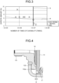
- FIG. 4 is a diagram illustrating a configuration in the vicinity of a cap of an accumulator according to the second embodiment of the present invention.
- the same portions as those of the accumulator 1 according to the first embodiment are denoted by the same reference numerals.
- An example in which the accumulator according to the second embodiment regulates the distance between the port 13 and the cap body 15 with the cap elastic portion 16 will be described.
- the hopeite amount in the cap body 15 is the same as that in the first embodiment.
- FIG. 4 illustrates a state in which the locking portion 132 of the port 13 and the cap elastic portion 16 are in contact with each other and the locking portion 132 does not apply a load to the cap elastic portion 16.
- the locking portion 132 includes a protrusion 132a protruding toward the cap body 15.
- the cap elastic portion 16 is in a natural state in which the cap elastic portion is not crushed by the load from the locking portion 132 and no load from the outside is applied other than gravity.
- the distance D between the port 13 and the cap body 15 is set according to the allowable deflection amount of the cap elastic portion 16 under the most severe use condition assumed.
- the distance D is a distance between the tip of the protrusion 132a and the cap body 15. That is, by setting the distance D, the load applied to the cap elastic portion 16 under the most severe use condition is limited.
- the durability of the cap elastic portion 16 fixed to the cap body 15 can be improved by regulating the hopeite amount on the bonding surface of the cap body 15.
- the second embodiment defining the distance D between the port 13 and the cap body 15 in the natural state and bringing the port 13 and the cap body 15 into contact with each other according to the applied load makes it possible to suppress the load applied to the cap elastic portion 16. According to the second embodiment, since the crushing of the cap elastic portion 16 is suppressed because the protrusion 132a and the cap body 15 are in contact with each other, the peeling of the cap elastic portion 16 from the cap body 15 can be more reliably suppressed.
- the present invention can include various embodiments and the like not described herein, and various design changes and the like can be made without departing from the technical idea specified by the claims.
- the cap bellows assembly and the accumulator according to the present invention are suitable for improving the durability of the elastic portion fixed to the body in the cap bellows assembly.
Landscapes
- Engineering & Computer Science (AREA)
- Chemical & Material Sciences (AREA)
- Mechanical Engineering (AREA)
- Physics & Mathematics (AREA)
- Fluid Mechanics (AREA)
- General Engineering & Computer Science (AREA)
- General Chemical & Material Sciences (AREA)
- Chemical Kinetics & Catalysis (AREA)
- Materials Engineering (AREA)
- Metallurgy (AREA)
- Organic Chemistry (AREA)
- Supply Devices, Intensifiers, Converters, And Telemotors (AREA)
- Diaphragms And Bellows (AREA)
Abstract
Description
- The present invention relates to a cap bellows assembly and an accumulator.
- In an accumulator, a bellows has conventionally been used as a fluid separation membrane or a fluid sealing membrane having airtightness and stretchability. The bellows is provided in an internal space formed by a bottom, a shell, and a port. The cap bellows assembly is formed of a metal body that is connected (welded) to the bellows to seal the gas, and a rubber elastic portion that seals the oil between the bellows and the shell called a backup fluid. The elastic portion is required to have durability against a load applied during operation of the accumulator. As a technique for suppressing peeling of the elastic portion from the body, a technique for enhancing adhesion strength by performing zinc calcium phosphate treatment is known (see, for example, Patent Literature 1).
- Patent Literature 1:
JP 2000-145804 A - However, zinc calcium phosphate treatment produces a relatively large crystal called hopeite (Zn3(PO4)2·4H2O). When stress concentrates on the hopeite at the bonded portion between the body and the elastic portion, the elastic portion may be peeled off from the body.
- The present invention has been made in view of the above, and an object of the present invention is to provide a cap bellows assembly and an accumulator capable of improving durability of an elastic portion fixed to a body.
- To solve the above-described problem and achieve the object, a cap bellows assembly according to the present invention seals one end of a bellows provided inside an exterior body of an accumulator, the accumulator including a bottom, a shell, and includes: a cap body configured to cover an opening of the bellows; and a cap elastic portion provided between the cap body and the port and fixed to the cap body, wherein a bonding surface of the cap body, to which the cap elastic portion is bonded, is subjected to a zinc calcium phosphate treatment, and a hopeite amount on the bonding surface is 4.8% or less.
- Moreover, in the above-described cap bellows assembly according to the present invention, the hopeite amount on the bonding surface is 3% or less.
- Moreover, in the above-described cap bellows assembly according to the present invention, a number of times of durability against peeling of the cap elastic portion from the cap body in a durability test in which pressure is repeatedly applied while the pressure is varied in a range of 0 to 21 MPa is 10 million times or more.
- Moreover, an accumulator according to the present invention includes: an exterior body including a bottom, a shell, and a port; a bellows provided inside the exterior body; and a cap bellows assembly configured to seal one end of the bellows, wherein the cap bellows assembly includes: a cap body configured to cover an opening of the bellows; and a cap elastic portion provided between the cap body and the port and fixed to the cap body, and a bonding surface of the cap body, to which the cap elastic portion is bonded, is subjected to a zinc calcium phosphate treatment, and a hopeite amount on the bonding surface is 4.8% or less.
- Moreover, in the above-described accumulator according to the present invention, the hopeite amount on the bonding surface is 3% or less.
- Moreover, in the above-described accumulator according to the present invention, the port includes a protrusion protruding toward the cap body, and a distance between the protrusion and the cap body is set according to an allowable deflection amount of the cap elastic portion. Advantageous Effects of Invention
- According to the present invention, it is possible to improve the durability of the elastic portion fixed to the body in the cap bellows assembly.
-
-
FIG. 1 is a sectional view illustrating a configuration of an accumulator according to a first embodiment of the present invention. -
FIG. 2 is a diagram illustrating a configuration of a cap of the accumulator illustrated inFIG. 1 . -
FIG. 3 is a diagram illustrating a relationship between the number of times of durability of an elastic portion and a hopeite amount. -
FIG. 4 is a diagram illustrating a configuration in the vicinity of a cap of an accumulator according to a second embodiment of the present invention. - Hereinafter, modes for carrying out the present invention (hereinafter, referred to as "embodiment") will be described with reference to the accompanying drawings. The drawings are schematic, and the relationship between the thickness and the width of each portion, the ratio of the thickness of each portion, and the like may be different from actual ones, and portions having different dimensional relationships and ratios may be included between the drawings.
-
FIG. 1 is a sectional view illustrating a configuration of an accumulator according to a first embodiment of the present invention. Anaccumulator 1 illustrated inFIG. 1 includes abottom 11, ashell 12, aport 13, abellows 14 housed in an internal space formed by thebottom 11, theshell 12, and theport 13, acap body 15, a capelastic portion 16, and aguide bellows 17. Thebottom 11, theshell 12, and theport 13 constitute an exterior body of theaccumulator 1. Thecap body 15 and the capelastic portion 16 constitute acap bellows assembly 100. - Here, the
bottom 11 and theport 13 are formed by using, for example, a cold-working material. Theshell 12 is formed by using a hot-working material, for example. - In the
accumulator 1, the space formed by thebottom 11, theshell 12, and theport 13 is divided by thebellows 14. Specifically, different spaces are formed between the outside and the inside of thebellows 14. The internal space of thebellows 14 communicates with the outside via ahole 11a of thebottom 11. The space outside thebellows 14 communicates with the outside via ahole 13a of theport 13.FIG. 1 illustrates an example in which the central axes of theholes accumulator 1. - The
bottom 11, theshell 12, and theport 13 are welded and fixed at respective connection portions. - In the
accumulator 1, a liquid (hydraulic oil) or a gas (for example, nitrogen gas) is sealed in each of a space (bellows external space) formed by the exterior body and thebellows 14 and the internal space of thebellows 14. For example, a liquid is introduced into the bellows external space, and a gas is enclosed in the internal space. - The
port 13 extends in a tubular shape and includes anintroduction portion 131 which is an introduction port of a liquid into theshell 12, and alocking portion 132 which is connected to one end of theintroduction portion 131 and is locked to an inner wall surface of theshell 12. - The
bellows 14 has a tubular shape. A side surface portion of thebellows 14 has an accordion shape formed by repeating an uneven shape, and it extends and contracts with an external load. In thebellows 14, the gap between theshell 12 and thebellows 14 is maintained by aguide bellows 17 provided on the outer peripheral side, and the bellows can smoothly extend and contract. Thebellows 14 is formed by using, for example, stainless steel (SUS304). Theguide bellows 17 is formed by using polybutylene terephthalate (PBT) or polyamide, for example. - The
cap body 15 has a plate shape and covers an opening of thebellows 14 on a side opposite to thebottom 11 side, and an end portion of thebellows 14 is welded to seal the opening. Thecap body 15 is constituted by using a material having durability to a pressure state (low pressure or high pressure) in theaccumulator 1. Thecap body 15 is formed by using, for example, metal, specifically, a steel plate hot commercial (SPHC). Thecap body 15 preferably has heat resistance according to a use state. - The cap
elastic portion 16 has a plate shape and is provided on the side of thecap body 15 opposite to thebellows 14 side. The capelastic portion 16 is positioned between theport 13 and thecap body 15, and it seals the liquid (hydraulic oil) between theshell 12 and thebellows 14. The capelastic portion 16 is formed by using, for example, acrylonitrile butadiene rubber (NBR). - The
cap body 15 and the capelastic portion 16 are formed by performing surface treatment by subjecting the bonding surface of thecap body 15 to phosphoric acid treatment, and then bonding the capelastic portion 16 to thecap body 15 by applying an adhesive or the like to the bonding surface. In the first embodiment, zinc calcium phosphate treatment is performed as the phosphoric acid treatment. - For example, when the bonding surface of the
cap body 15 is subjected to zinc calcium phosphate, a relatively large crystal called hopeite (Zn3(PO4)2·4H2O) is produced. The hopeite is a crystal having a relatively large size in which stress concentration occurs when stress is applied. In the first embodiment, durability against repeated use of theaccumulator 1 is imparted by defining the amount of the hopeite. - In the first embodiment, the hopeite amount after the surface treatment on the
cap body 15 is 4.8% or less. It is preferably 3% or less from the viewpoint of obtaining reliable durability. The hopeite amount corresponds to the amount of hopeite on the bonding surface of the capelastic portion 16 of thecap body 15. As a method for calculating the hopeite amount, for example, first, a part of the bonding surface is observed with a scanning electron microscope (SEM), and a crystal having a larger size than other crystals is extracted as hopeite from an obtained SEM image. Thereafter, the existence ratio of the extracted hopeite is calculated, and the hopeite amount is determined as a value obtained by converting this existence ratio into the bonding area. For the extraction of hopeite, an observer may specify the hopeite, of the image processing (for example, contour extraction) may be performed to extract the hopeite. - In the
accumulator 1, when the pressure of the line connected to theaccumulator 1 changes through supplying/sucking the liquid via thehole 13a of theport 13, the fluid flows in from thehole 13a of theport 13, and the cap bellowsassembly 100 is pushed up. The pressure in the space between thebellows 14 and theshell 12 is always the same as the pressure inside the bellows 14. - When the pressure (hydraulic pressure) of the line is 0, the load applied to the cap
elastic portion 16 becomes the largest. At this time, the sealing pressure of theaccumulator 1 is applied to the capelastic portion 16. In a case where the hydraulic oil flows in from thehole 13a due to an increase in the hydraulic pressure of the line, thebellows 14 contracts when the hydraulic oil reaches a pressure equal to or higher than the sealing pressure of theaccumulator 1. When the hydraulic pressure of the line decreases and thebellows 14 extends (returns) from the contracted state, the hydraulic oil is discharged from thehole 13a to the outside. The pressurized state with theaccumulator 1 is controlled by the discharge of the liquid from thehole 13a. In addition, due to repeated use of theaccumulator 1, a load is applied to the capelastic portion 16. - As an example, the results of a peeling durability test with a test piece in which the cap
elastic portion 16 is attached to thecap body 15 are shown in Table 1. In the peeling durability test, the number of times of durability until the capelastic portion 16 peeled off from thecap body 15 or until the number of times of durability exceeded a predetermined number (10 million times as the number of times of repetition this time) was measured in a case where the sealing pressure of theaccumulator 1 was set to 13 MPa, the test temperature was set to 80°C, the test pressure applied to thebellows 14 was varied at 0 to 21 MPa, and theaccumulator 1 was repeatedly stopped and operated to receive stress.FIG. 3 is a diagram illustrating a relationship between the number of times of durability of the elastic portion and the hopeite amount in the test piece shown in Table 1. In the peeling durability test, when the number of repetitions (number of times of durability) exceeds 10 million (the reference line S inFIG. 3 ), the test was terminated even when the capelastic portion 16 was not peeled off from thecap body 15.Table 1 Test piece No. Hopeite amount (%) Number of times of durability Durability result 1 1.1 15,500,000 OK (Terminated) 2 1.8 11,100,723 OK (Terminated) 3 1.8 11,100,723 OK (Terminated) 4 4.8 10,360,585 OK (Terminated) 5 6.9 5,211,016 NG 6 6.9 2,413,460 NG 7 6.9 1,978,740 NG 8 6.9 1,000,000 NG 9 6.9 1,000,000 NG 10 6.9 543,290 NG 11 12.7 723,505 NG - As shown in Table 1 and
FIG. 3 , when the hopeite amount is 4.8% or less, durability of 10 million times or more is achieved. On the other hand, it can be seen that when the hopeite amount is large (6.9% and 12.7% here), the number of times of durability does not reach 10 million times, and the durability is not satisfied. From these results, it can be said that the durability of 10 million times is satisfied when the hopeite amount is 4.8% or less. In addition, from the obtained results, for example, it is possible to generate a boundary line R (seeFIG. 3 ) that defines an upper limit value of the hopeite amount satisfying the durability with respect to a predetermined number of times of durability in the relationship between the number of times of durability and the hopeite amount. - According to the first embodiment, the durability of the cap
elastic portion 16 fixed to thecap body 15 can be improved by regulating the hopeite amount on the bonding surface of thecap body 15. In particular, by applying the cap bellows assembly 100 according to the first embodiment to an accumulator of a relatively high pressure sealed type as the type of theaccumulator 1, an accumulator having excellent durability can be obtained. - Next, a second embodiment of the present invention will be described with reference to
FIG. 4. FIG. 4 is a diagram illustrating a configuration in the vicinity of a cap of an accumulator according to the second embodiment of the present invention. The same portions as those of theaccumulator 1 according to the first embodiment are denoted by the same reference numerals. An example in which the accumulator according to the second embodiment regulates the distance between theport 13 and thecap body 15 with the capelastic portion 16 will be described. The hopeite amount in thecap body 15 is the same as that in the first embodiment. -
FIG. 4 illustrates a state in which the lockingportion 132 of theport 13 and the capelastic portion 16 are in contact with each other and the lockingportion 132 does not apply a load to the capelastic portion 16. In the second embodiment, the lockingportion 132 includes aprotrusion 132a protruding toward thecap body 15. InFIG. 4 , the capelastic portion 16 is in a natural state in which the cap elastic portion is not crushed by the load from the lockingportion 132 and no load from the outside is applied other than gravity. In this natural state, the distance D between theport 13 and thecap body 15 is set according to the allowable deflection amount of the capelastic portion 16 under the most severe use condition assumed. In the first embodiment, the distance D is a distance between the tip of theprotrusion 132a and thecap body 15. That is, by setting the distance D, the load applied to the capelastic portion 16 under the most severe use condition is limited. - According to the second embodiment, as in the first embodiment, the durability of the cap
elastic portion 16 fixed to thecap body 15 can be improved by regulating the hopeite amount on the bonding surface of thecap body 15. - Further, in the second embodiment, defining the distance D between the
port 13 and thecap body 15 in the natural state and bringing theport 13 and thecap body 15 into contact with each other according to the applied load makes it possible to suppress the load applied to the capelastic portion 16. According to the second embodiment, since the crushing of the capelastic portion 16 is suppressed because theprotrusion 132a and thecap body 15 are in contact with each other, the peeling of the capelastic portion 16 from thecap body 15 can be more reliably suppressed. - Although an embodiment for carrying out the present invention have been described so far, the present invention should not be limited only by the above-described embodiment.
- As described here, the present invention can include various embodiments and the like not described herein, and various design changes and the like can be made without departing from the technical idea specified by the claims.
- As described above, the cap bellows assembly and the accumulator according to the present invention are suitable for improving the durability of the elastic portion fixed to the body in the cap bellows assembly.
-
- 1
- ACCUMULATOR
- 11
- BOTTOM
- 12
- SHELL
- 13
- PORT
- 14
- BELLOWS
- 15
- CAP BODY
- 16
- CAP ELASTIC PORTION
- 17
- GUIDE BELLOWS
- 100
- CAP BELLOWS ASSEMBLY
Claims (6)
- A cap bellows assembly for sealing one end of a bellows provided inside an exterior body of an accumulator, the accumulator including a bottom, a shell, and a port, the cap bellows assembly comprising:a cap body configured to cover an opening of the bellows; anda cap elastic portion provided between the cap body and the port and fixed to the cap body, whereina bonding surface of the cap body, to which the cap elastic portion is bonded, is subjected to a zinc calcium phosphate treatment, anda hopeite amount on the bonding surface is 4.8% or less.
- The cap bellows assembly according to claim 1, wherein the hopeite amount on the bonding surface is 3% or less.
- The cap bellows assembly according to claim 1, wherein a number of times of durability against peeling of the cap elastic portion from the cap body in a durability test in which pressure is repeatedly applied while the pressure is varied in a range of 0 to 21 MPa is 10 million times or more.
- An accumulator comprising:an exterior body including a bottom, a shell, and a port;a bellows provided inside the exterior body; anda cap bellows assembly configured to seal one end of the bellows, whereinthe cap bellows assembly includes:a cap body configured to cover an opening of the bellows; anda cap elastic portion provided between the cap body and the port and fixed to the cap body, anda bonding surface of the cap body, to which the cap elastic portion is bonded, is subjected to a zinc calcium phosphate treatment, anda hopeite amount on the bonding surface is 4.8% or less.
- The accumulator according to claim 4, wherein the hopeite amount on the bonding surface is 3% or less.
- The accumulator according to claim 4 or 5,
whereinthe port includes a protrusion protruding toward the cap body, anda distance between the protrusion and the cap body is set according to an allowable deflection amount of the cap elastic portion.
Applications Claiming Priority (2)
| Application Number | Priority Date | Filing Date | Title |
|---|---|---|---|
| JP2022013278A JP2023111425A (en) | 2022-01-31 | 2022-01-31 | Cap bellows assembly and accumulator |
| PCT/JP2023/001608 WO2023145621A1 (en) | 2022-01-31 | 2023-01-20 | Cap bellows assembly and accumulator |
Publications (2)
| Publication Number | Publication Date |
|---|---|
| EP4474657A1 true EP4474657A1 (en) | 2024-12-11 |
| EP4474657A4 EP4474657A4 (en) | 2025-04-30 |
Family
ID=87471736
Family Applications (1)
| Application Number | Title | Priority Date | Filing Date |
|---|---|---|---|
| EP23746834.3A Pending EP4474657A4 (en) | 2022-01-31 | 2023-01-20 | Cap bellows assembly and accumulator |
Country Status (5)
| Country | Link |
|---|---|
| US (1) | US20250146513A1 (en) |
| EP (1) | EP4474657A4 (en) |
| JP (1) | JP2023111425A (en) |
| CN (1) | CN118511000A (en) |
| WO (1) | WO2023145621A1 (en) |
Family Cites Families (6)
| Publication number | Priority date | Publication date | Assignee | Title |
|---|---|---|---|---|
| JPH0676675B2 (en) * | 1989-05-29 | 1994-09-28 | 新日本製鐵株式会社 | Method for producing galvanized steel sheet with excellent chemical conversion treatability and post-painting performance |
| JPH11247862A (en) * | 1998-03-06 | 1999-09-14 | Nippon Seiko Kk | Sealed roller bearing |
| JP2000145804A (en) | 1998-11-09 | 2000-05-26 | Sumikou Junkatsuzai Kk | Barfield constant velocity joint |
| JP2003301801A (en) * | 2002-04-12 | 2003-10-24 | Nok Corp | Accumulator |
| DE102004036481B4 (en) * | 2003-07-30 | 2020-07-23 | Nhk Spring Co., Ltd. | Vehicle brake system component |
| JP4718129B2 (en) * | 2003-07-30 | 2011-07-06 | 日本発條株式会社 | Brake system parts for vehicles |
-
2022
- 2022-01-31 JP JP2022013278A patent/JP2023111425A/en active Pending
-
2023
- 2023-01-20 CN CN202380016302.5A patent/CN118511000A/en active Pending
- 2023-01-20 WO PCT/JP2023/001608 patent/WO2023145621A1/en not_active Ceased
- 2023-01-20 US US18/726,139 patent/US20250146513A1/en active Pending
- 2023-01-20 EP EP23746834.3A patent/EP4474657A4/en active Pending
Also Published As
| Publication number | Publication date |
|---|---|
| JP2023111425A (en) | 2023-08-10 |
| WO2023145621A1 (en) | 2023-08-03 |
| US20250146513A1 (en) | 2025-05-08 |
| EP4474657A4 (en) | 2025-04-30 |
| CN118511000A (en) | 2024-08-16 |
Similar Documents
| Publication | Publication Date | Title |
|---|---|---|
| EP3675205A1 (en) | Sealing plate | |
| US8859139B2 (en) | Alkaline storage battery | |
| US8246056B2 (en) | Superplastic sealing system, preferentialy for electrochemical cell system | |
| US20100304214A1 (en) | Sealed battery | |
| US9497847B2 (en) | Port member of superconducting accelerating cavity | |
| EP4474657A1 (en) | Cap bellows assembly and accumulator | |
| US9777726B2 (en) | Compressor with valve pressing portions for sealing | |
| CN208336404U (en) | Battery and its coping plate component | |
| EP4007044B1 (en) | Method of manufacturing pouch-shaped battery cell using fixing jig and pouch-shaped battery cell manufactured using the same | |
| US20040137307A1 (en) | Seal construction for fuel cell | |
| EP2436065B1 (en) | Process for making fill hole in a wall of an energy storage device | |
| CN101994833A (en) | Laminate assembly sealing method and arrangement | |
| EP3663616B1 (en) | Metal gasket | |
| EP3865738A1 (en) | Metal gasket | |
| US20250215905A1 (en) | Accumulator | |
| CN113611964A (en) | Steel gasket, lithium ion battery and sealed container with sealing function | |
| JP4239487B2 (en) | Self-tightening method for ultra-high pressure vessel | |
| JPH11303744A (en) | Hermetic compressor | |
| EP4481922A3 (en) | Valve assembly for a battery enclosure | |
| JPH03203157A (en) | Manufacture of sealed battery | |
| US20220069394A1 (en) | Sealing structure for battery | |
| CN203548870U (en) | Pressure vessel | |
| EP3961745A1 (en) | Sealing structure for battery | |
| CN218787320U (en) | Special-shaped sealing ring with framework | |
| JPH11339736A (en) | Cylindrical battery and manufacture of positive electrode case thereof |
Legal Events
| Date | Code | Title | Description |
|---|---|---|---|
| STAA | Information on the status of an ep patent application or granted ep patent |
Free format text: STATUS: THE INTERNATIONAL PUBLICATION HAS BEEN MADE |
|
| PUAI | Public reference made under article 153(3) epc to a published international application that has entered the european phase |
Free format text: ORIGINAL CODE: 0009012 |
|
| STAA | Information on the status of an ep patent application or granted ep patent |
Free format text: STATUS: REQUEST FOR EXAMINATION WAS MADE |
|
| 17P | Request for examination filed |
Effective date: 20240709 |
|
| AK | Designated contracting states |
Kind code of ref document: A1 Designated state(s): AL AT BE BG CH CY CZ DE DK EE ES FI FR GB GR HR HU IE IS IT LI LT LU LV MC ME MK MT NL NO PL PT RO RS SE SI SK SM TR |
|
| A4 | Supplementary search report drawn up and despatched |
Effective date: 20250331 |
|
| RIC1 | Information provided on ipc code assigned before grant |
Ipc: F15B 1/10 20060101ALI20250325BHEP Ipc: C23C 22/12 20060101ALI20250325BHEP Ipc: F15B 1/16 20060101AFI20250325BHEP |
|
| DAV | Request for validation of the european patent (deleted) | ||
| DAX | Request for extension of the european patent (deleted) |