EP4474651A1 - Rotary compressor and refrigeration apparatus - Google Patents
Rotary compressor and refrigeration apparatus Download PDFInfo
- Publication number
- EP4474651A1 EP4474651A1 EP23774514.6A EP23774514A EP4474651A1 EP 4474651 A1 EP4474651 A1 EP 4474651A1 EP 23774514 A EP23774514 A EP 23774514A EP 4474651 A1 EP4474651 A1 EP 4474651A1
- Authority
- EP
- European Patent Office
- Prior art keywords
- flow path
- refrigerant
- space
- motor
- rotary compressor
- Prior art date
- Legal status (The legal status is an assumption and is not a legal conclusion. Google has not performed a legal analysis and makes no representation as to the accuracy of the status listed.)
- Granted
Links
Images






Classifications
-
- F—MECHANICAL ENGINEERING; LIGHTING; HEATING; WEAPONS; BLASTING
- F04—POSITIVE - DISPLACEMENT MACHINES FOR LIQUIDS; PUMPS FOR LIQUIDS OR ELASTIC FLUIDS
- F04B—POSITIVE-DISPLACEMENT MACHINES FOR LIQUIDS; PUMPS
- F04B39/00—Component parts, details, or accessories, of pumps or pumping systems specially adapted for elastic fluids, not otherwise provided for in, or of interest apart from, groups F04B25/00 - F04B37/00
- F04B39/12—Casings; Cylinders; Cylinder heads; Fluid connections
-
- F—MECHANICAL ENGINEERING; LIGHTING; HEATING; WEAPONS; BLASTING
- F25—REFRIGERATION OR COOLING; COMBINED HEATING AND REFRIGERATION SYSTEMS; HEAT PUMP SYSTEMS; MANUFACTURE OR STORAGE OF ICE; LIQUEFACTION SOLIDIFICATION OF GASES
- F25B—REFRIGERATION MACHINES, PLANTS OR SYSTEMS; COMBINED HEATING AND REFRIGERATION SYSTEMS; HEAT PUMP SYSTEMS
- F25B31/00—Compressor arrangements
- F25B31/02—Compressor arrangements of motor-compressor units
- F25B31/026—Compressor arrangements of motor-compressor units with compressor of rotary type
-
- F—MECHANICAL ENGINEERING; LIGHTING; HEATING; WEAPONS; BLASTING
- F04—POSITIVE - DISPLACEMENT MACHINES FOR LIQUIDS; PUMPS FOR LIQUIDS OR ELASTIC FLUIDS
- F04B—POSITIVE-DISPLACEMENT MACHINES FOR LIQUIDS; PUMPS
- F04B39/00—Component parts, details, or accessories, of pumps or pumping systems specially adapted for elastic fluids, not otherwise provided for in, or of interest apart from, groups F04B25/00 - F04B37/00
- F04B39/02—Lubrication
-
- F—MECHANICAL ENGINEERING; LIGHTING; HEATING; WEAPONS; BLASTING
- F04—POSITIVE - DISPLACEMENT MACHINES FOR LIQUIDS; PUMPS FOR LIQUIDS OR ELASTIC FLUIDS
- F04B—POSITIVE-DISPLACEMENT MACHINES FOR LIQUIDS; PUMPS
- F04B39/00—Component parts, details, or accessories, of pumps or pumping systems specially adapted for elastic fluids, not otherwise provided for in, or of interest apart from, groups F04B25/00 - F04B37/00
- F04B39/04—Measures to avoid lubricant contaminating the pumped fluid
-
- F—MECHANICAL ENGINEERING; LIGHTING; HEATING; WEAPONS; BLASTING
- F04—POSITIVE - DISPLACEMENT MACHINES FOR LIQUIDS; PUMPS FOR LIQUIDS OR ELASTIC FLUIDS
- F04C—ROTARY-PISTON, OR OSCILLATING-PISTON, POSITIVE-DISPLACEMENT MACHINES FOR LIQUIDS; ROTARY-PISTON, OR OSCILLATING-PISTON, POSITIVE-DISPLACEMENT PUMPS
- F04C23/00—Combinations of two or more pumps, each being of rotary-piston or oscillating-piston type, specially adapted for elastic fluids; Pumping installations specially adapted for elastic fluids; Multi-stage pumps specially adapted for elastic fluids
- F04C23/008—Hermetic pumps
-
- F—MECHANICAL ENGINEERING; LIGHTING; HEATING; WEAPONS; BLASTING
- F04—POSITIVE - DISPLACEMENT MACHINES FOR LIQUIDS; PUMPS FOR LIQUIDS OR ELASTIC FLUIDS
- F04C—ROTARY-PISTON, OR OSCILLATING-PISTON, POSITIVE-DISPLACEMENT MACHINES FOR LIQUIDS; ROTARY-PISTON, OR OSCILLATING-PISTON, POSITIVE-DISPLACEMENT PUMPS
- F04C29/00—Component parts, details or accessories of pumps or pumping installations, not provided for in groups F04C18/00 - F04C28/00
- F04C29/02—Lubrication; Lubricant separation
- F04C29/026—Lubricant separation
-
- F—MECHANICAL ENGINEERING; LIGHTING; HEATING; WEAPONS; BLASTING
- F04—POSITIVE - DISPLACEMENT MACHINES FOR LIQUIDS; PUMPS FOR LIQUIDS OR ELASTIC FLUIDS
- F04C—ROTARY-PISTON, OR OSCILLATING-PISTON, POSITIVE-DISPLACEMENT MACHINES FOR LIQUIDS; ROTARY-PISTON, OR OSCILLATING-PISTON, POSITIVE-DISPLACEMENT PUMPS
- F04C29/00—Component parts, details or accessories of pumps or pumping installations, not provided for in groups F04C18/00 - F04C28/00
- F04C29/04—Heating; Cooling; Heat insulation
- F04C29/045—Heating; Cooling; Heat insulation of the electric motor in hermetic pumps
-
- F—MECHANICAL ENGINEERING; LIGHTING; HEATING; WEAPONS; BLASTING
- F25—REFRIGERATION OR COOLING; COMBINED HEATING AND REFRIGERATION SYSTEMS; HEAT PUMP SYSTEMS; MANUFACTURE OR STORAGE OF ICE; LIQUEFACTION SOLIDIFICATION OF GASES
- F25B—REFRIGERATION MACHINES, PLANTS OR SYSTEMS; COMBINED HEATING AND REFRIGERATION SYSTEMS; HEAT PUMP SYSTEMS
- F25B31/00—Compressor arrangements
- F25B31/006—Cooling of compressor or motor
-
- F—MECHANICAL ENGINEERING; LIGHTING; HEATING; WEAPONS; BLASTING
- F04—POSITIVE - DISPLACEMENT MACHINES FOR LIQUIDS; PUMPS FOR LIQUIDS OR ELASTIC FLUIDS
- F04C—ROTARY-PISTON, OR OSCILLATING-PISTON, POSITIVE-DISPLACEMENT MACHINES FOR LIQUIDS; ROTARY-PISTON, OR OSCILLATING-PISTON, POSITIVE-DISPLACEMENT PUMPS
- F04C18/00—Rotary-piston pumps specially adapted for elastic fluids
- F04C18/02—Rotary-piston pumps specially adapted for elastic fluids of arcuate-engagement type, i.e. with circular translatory movement of co-operating members, each member having the same number of teeth or tooth-equivalents
- F04C18/0207—Rotary-piston pumps specially adapted for elastic fluids of arcuate-engagement type, i.e. with circular translatory movement of co-operating members, each member having the same number of teeth or tooth-equivalents both members having co-operating elements in spiral form
- F04C18/0215—Rotary-piston pumps specially adapted for elastic fluids of arcuate-engagement type, i.e. with circular translatory movement of co-operating members, each member having the same number of teeth or tooth-equivalents both members having co-operating elements in spiral form where only one member is moving
Definitions
- the present disclosure relates to a rotary compressor and a refrigeration apparatus.
- Patent Document 1 discloses a compressor including a gas guide that forms a gas flow path together with an inner surface of a casing.
- the gas guide is joined to the casing by spot welding.
- the gas guide discharges part of a refrigerant compressed by a compression mechanism along the circumferential direction of the casing to separate a lubricant contained in the refrigerant.
- Patent Document 1 Japanese Patent No. 5429319
- Patent Document 1 requires a process of spot-welding the gas guide to the casing. This increases the number of operation processes. Thus, there has been a demand to generate a flow of the refrigerant swirling along the circumferential direction of the casing without using the gas guide.
- a first aspect of the present disclosure is directed to a rotary compressor including: a casing (20); a compression mechanism (40) housed inside the casing (20) and configured to compress a refrigerant; a drive shaft (11) configured to drive the compression mechanism (40); and a motor (30) configured to rotate the drive shaft (11),
- the rotary compressor including: a partitioning member (50) housed inside the casing (20), wherein the partitioning member (50) partitions an interior of the casing (20) into a first space (23) into which the refrigerant compressed by the compression mechanism (40) is discharged and a second space (24) provided between the partitioning member (50) and the motor (30), the partitioning member (50) has a discharge flow path (80) through which the refrigerant is discharged from the first space (23) to the second space (24), and the discharge flow path (80) includes an inclined flow path (81) that extends while inclining toward downstream in a direction of rotation of the motor (30).
- making the refrigerant flow along the inclined flow path (81) generates the flow of the refrigerant swirling along the circumferential direction of the casing (20) in the second space (24), which makes it possible to separate the lubricant contained in the refrigerant.
- a second aspect of the present disclosure is an embodiment of the rotary compressor of the first aspect.
- the discharge flow path (80) includes an axial flow path (82) that is continuous with an upstream side of the inclined flow path (81) and extends along an axial direction of the motor (30).
- providing the inclined flow path (81) to be continuous with the axial flow path (82) makes it possible for the inclined flow path (81) to have an acute angle of inclination as compared to a case where no axial flow path (82) is provided.
- the refrigerant can swirl along the circumferential direction of the casing (20) in the second space (24) easily.
- the refrigerant flowing along the axial flow path (82) collides with the inclined flow path (81), which causes the lubricant contained in the refrigerant to be separated in the inclined flow path (81) and then the refrigerant to flow down along the inclined flow path (81). This facilitates the separation of the refrigerant and the lubricant from each other.
- increasing the flow path width of a downstream portion of the inclined flow path (81) allows the refrigerant to flow smoothly from the inclined flow path (81) toward the second space (24).
- a ninth aspect of the present disclosure is an embodiment of the rotary compressor of the eighth aspect.
- a downstream end (P3) of the first flow path (83) on the first surface (81a) is closer to the first space (23) than a downstream end (P4) of the second surface (81b) as viewed in the axial direction of the motor (30).
- a tenth aspect of the present disclosure is directed to a refrigeration apparatus including: the rotary compressor (10) of any one of the first to ninth aspects; and a refrigerant circuit (1a) through which a refrigerant compressed by the rotary compressor (10) flows.
- a refrigeration apparatus including the rotary compressor (10) can be provided.
- the refrigeration apparatus (1) is an air conditioner.
- the air conditioner may be a cooling-only apparatus, a heating-only apparatus, or an air conditioner switchable between cooling and heating.
- the air conditioner has a switching mechanism (e.g., a four-way switching valve) configured to switch the direction of circulation of the refrigerant.
- the refrigeration apparatus (1) may be a water heater, a chiller unit, or a cooling apparatus configured to cool air in an internal space.
- the cooling apparatus cools the air in a refrigerator, a freezer, or a container, for example.
- the motor (30) includes a stator (31) and a rotor (32).
- the stator (31) is fixed to the inner circumferential surface of the casing (20).
- the rotor (32) is disposed inside the stator (31).
- a drive shaft (11) passes through the rotor (32).
- the rotor (32) is fixed to the drive shaft (11).
- the drive shaft (11) is provided with a balance weight (18).
- the casing (20) has, at its bottom, an oil reservoir (21).
- the oil reservoir (21) stores a lubricant.
- a suction pipe (12) is connected to an upper portion of the casing (20).
- a discharge pipe (13) is connected to a barrel of the casing (20).
- a housing (50) serving as a partitioning member is fixed to the casing (20).
- the housing (50) is made of a casting.
- the housing (50) is fixed to the inside of the casing (20) by, for example, shrink fitting.
- the housing (50) is located above the motor (30).
- the compression mechanism (40) is located above the housing (50).
- the discharge pipe (13) has an inflow end between the motor (30) and the housing (50).
- the interior of the casing (20) has a first space (23) and a second space (24) partitioned by the housing (50).
- the first space (23) is a space above the housing (50).
- the high-pressure refrigerant compressed by the compression mechanism (40) is discharged to the first space (23).
- the second space (24) is a space provided between the housing (50) and the motor (30).
- the housing (50) has a discharge flow path (80) through which the refrigerant is discharged from the first space (23) toward the second space (24) (see FIG. 3 ).
- the housing (50) has a recess (53).
- the recess (53) is a recessed portion of the upper surface of the housing (50).
- An upper bearing (51) is located below the recess (53). The upper bearing (51) rotatably supports the drive shaft (11).
- the drive shaft (11) extends vertically along the center axis of the casing (20).
- the drive shaft (11) has a main shaft portion (14) and an eccentric portion (15).
- the fixed end plate (61) is located on the outer circumference and is continuous with the fixed wrap (62).
- the end surface of the fixed wrap (62) and the end surface of the outer circumferential wall (63) are substantially flush with each other.
- the fixed scroll (60) is fixed to the housing (50).
- the boss (73) is formed on a central portion of the lower surface of the movable end plate (71).
- the eccentric portion (15) of the drive shaft (11) is inserted into the boss (73), whereby the boss (73) is connected to the drive shaft (11).
- the outer circumferential wall (63) of the fixed scroll (60) has a suction port (64).
- the suction port (64) is open near the winding end of the fixed wrap (62).
- a downstream end of the suction pipe (12) is connected to the suction port (64).
- the fixed end plate (61) of the fixed scroll (60) has, at its center, an outlet (65).
- the outlet (65) is open to the upper surface of the fixed end plate (61) of the fixed scroll (60).
- the high-pressure refrigerant discharged from the outlet (65) is discharged into the first space (23) above the housing (50).
- the refrigerant discharged into the first space (23) is discharged to the second space (24) through the fixed flow path (66) of the fixed scroll (60) and the discharge flow path (80) of the housing (50) (see FIG. 3 ).
- the recess (53) of the housing (50) communicates with the oil supply passage (16) of the drive shaft (11) via the inside of the boss (73) of the movable scroll (70).
- the high-pressure lubricant is supplied to the recess (53), so that a high pressure equivalent to the discharge pressure of the compression mechanism (40) acts on the recess (53).
- the movable scroll (70) is pressed onto the fixed scroll (60) by the high pressure that acts on the recess (53).
- a fixed flow path (66) is provided in a side surface of the fixed scroll (60).
- the fixed flow path (66) is formed between a recessed portion of the side surface of the fixed scroll (60) and the inner circumferential surface of the casing (20).
- the fixed flow path (66) extends in the axial direction.
- the discharge flow path (80) is provided in a side surface of the housing (50).
- the discharge flow path (80) is formed between a recessed portion of the side surface of the housing (50) and the inner circumferential surface of the casing (20).
- the upstream end of the discharge flow path (80) communicates with the downstream end of the fixed flow path (66) of the fixed scroll (60).
- the downstream end of the discharge flow path (80) communicates with the second space (24).
- the inclined flow path (81) is a so-called "divergent" flow path having a downstream portion whose flow path width is greater than the flow path width of its upstream portion.
- the inclined flow path (81) may have a constant flow path width from the upstream side to the downstream side.
- the high-pressure refrigerant discharged from the outlet (65) of the compression mechanism (40) into the first space (23) is discharged into the second space (24) via the fixed flow path (66) of the fixed scroll (60) and the discharge flow path (80) of the housing (50).
- the refrigerant passing through the discharge flow path (80) flows along the direction of inclination of the inclined flow path (81).
- the refrigerant flows toward downstream in the direction of rotation of the motor (30).
- the refrigerant passing through the discharge flow path (80) flows along the direction of inclination of the inclined flow path (81).
- the refrigerant that has passed through the discharge flow path (80) is discharged into the second space (24), and then swirls along the inner circumferential surface of the casing (20) in the circumferential direction.
- the discharge flow path (80) is branched into the inclined flow path (81) and the branch flow path (85) on the downstream side of the axial flow path (82).
- the refrigerant flowing from the first space (23) and passing through the axial flow path (82) of the discharge flow path (80) is divided into the inclined flow path (81) and the branch flow path (85).
- the refrigerant flowing through the inclined flow path (81) swirls in the circumferential direction in the second space (24) along the inner circumferential surface of the casing (20).
- the refrigerant flowing through the branch flow path (85) is discharged toward the motor (30) in the second space (24) to cool the motor (30).
- angle ⁇ the angle formed between a phantom plane (91) passing through any point (P) on the first surface (81a) and extending along the first surface (81a) and a reference phantom plane (95) orthogonal to the axial direction of the motor (30) is referred to as an "angle ⁇ .”
- the shape of the inclined flow path (81) is determined so that the first angle ⁇ 1 and the second angle ⁇ 2 satisfy the condition " ⁇ 1 ⁇ ⁇ 2.”
- increasing the flow path width of a downstream portion of the inclined flow path (81) allows the refrigerant to flow smoothly from the inclined flow path (81) toward the second space (24).
- the discharge flow path (80) is provided in a side surface of the housing (50).
- the discharge flow path (80) includes an inclined flow path (81) and an axial flow path (82).
- the inclined flow path (81) extends while inclining toward downstream in the direction of rotation of the motor (30).
- the axial flow path (82) is continuous with the upstream side of the inclined flow path (81), and extends along the axial direction of the motor (30).
- the inclined flow path (81) has a first surface (81a) and a second surface (81b).
- the first surface (81a) is a surface with which the refrigerant that has flowed from the first space (23) collides and guides the refrigerant toward the second space (24).
- the second surface (81b) faces the first surface (81a).
- the downstream end (P3) of the first flow path (83) on the first surface (81a) is closer to the first space (23) than the downstream end (P4) of the second surface (81b) as viewed in the axial direction of the motor (30).
- the downstream end (P1) of the first surface (81a) is closer to the second space (24) than the downstream end (P4) of the second surface (81b) as viewed in the axial direction of the motor (30).
- the angle formed between a phantom plane (91) passing through the upstream end (P2) of the first surface (81a) and extending along the first surface (81a) and a reference phantom plane (95) orthogonal to the axial direction of the motor (30), i.e., the angle ⁇ at the point (P) located at the upstream end (P2) of the first surface (81a), is referred to as a "second angle ⁇ 2.”
- the shape of the inclined flow path (81) is determined so that the first angle ⁇ 1 and the second angle ⁇ 2 satisfy the condition " ⁇ 1 ⁇ ⁇ 2.”
- expanding the portion where the flow path width of the inclined flow path (81) is increased allows the refrigerant to flow smoothly from the inclined flow path (81) toward the second space (24).
- the discharge flow path (80) is provided in the housing (50), but is not limited thereto.
- the discharge flow path (80) may be provided in the fixed scroll (60) serving as a partitioning member.
- the discharge flow path (80) is formed between a recessed portion of the side surface of the housing (50) and the inner peripheral surface of the casing (20), but is not limited thereto.
- a tubular flow path member (86) forming the discharge flow path (80) may be separately embedded in the recessed portion of the side surface of the housing (50) to form the discharge flow path (80) in the housing (50).
- the present disclosure is useful for a rotary compressor and a refrigeration apparatus.
Landscapes
- Engineering & Computer Science (AREA)
- Mechanical Engineering (AREA)
- General Engineering & Computer Science (AREA)
- Physics & Mathematics (AREA)
- Thermal Sciences (AREA)
- Applications Or Details Of Rotary Compressors (AREA)
- Compressor (AREA)
- Rotary Pumps (AREA)
Abstract
Description
- The present disclosure relates to a rotary compressor and a refrigeration apparatus.
- Patent Document 1 discloses a compressor including a gas guide that forms a gas flow path together with an inner surface of a casing. The gas guide is joined to the casing by spot welding. The gas guide discharges part of a refrigerant compressed by a compression mechanism along the circumferential direction of the casing to separate a lubricant contained in the refrigerant.
- Patent Document 1:
Japanese Patent No. 5429319 - The invention of Patent Document 1 requires a process of spot-welding the gas guide to the casing. This increases the number of operation processes. Thus, there has been a demand to generate a flow of the refrigerant swirling along the circumferential direction of the casing without using the gas guide.
- It is an object of the present disclosure to provide a rotary compressor that generates a flow of a refrigerant swirling along the circumferential direction of a casing.
- A first aspect of the present disclosure is directed to a rotary compressor including: a casing (20); a compression mechanism (40) housed inside the casing (20) and configured to compress a refrigerant; a drive shaft (11) configured to drive the compression mechanism (40); and a motor (30) configured to rotate the drive shaft (11), the rotary compressor including: a partitioning member (50) housed inside the casing (20), wherein the partitioning member (50) partitions an interior of the casing (20) into a first space (23) into which the refrigerant compressed by the compression mechanism (40) is discharged and a second space (24) provided between the partitioning member (50) and the motor (30), the partitioning member (50) has a discharge flow path (80) through which the refrigerant is discharged from the first space (23) to the second space (24), and the discharge flow path (80) includes an inclined flow path (81) that extends while inclining toward downstream in a direction of rotation of the motor (30).
- According to the first aspect, making the refrigerant flow along the inclined flow path (81) generates the flow of the refrigerant swirling along the circumferential direction of the casing (20) in the second space (24), which makes it possible to separate the lubricant contained in the refrigerant.
- A second aspect of the present disclosure is an embodiment of the rotary compressor of the first aspect. In the second aspect, the discharge flow path (80) includes an axial flow path (82) that is continuous with an upstream side of the inclined flow path (81) and extends along an axial direction of the motor (30).
- According to the second aspect, providing the inclined flow path (81) to be continuous with the axial flow path (82) makes it possible for the inclined flow path (81) to have an acute angle of inclination as compared to a case where no axial flow path (82) is provided. Thus, the refrigerant can swirl along the circumferential direction of the casing (20) in the second space (24) easily.
- The refrigerant flowing along the axial flow path (82) collides with the inclined flow path (81), which causes the lubricant contained in the refrigerant to be separated in the inclined flow path (81) and then the refrigerant to flow down along the inclined flow path (81). This facilitates the separation of the refrigerant and the lubricant from each other.
- A third aspect of the present disclosure is an embodiment of the rotary compressor of the second aspect. In the third aspect, a joint portion between the axial flow path (82) and the inclined flow path (81) is curved.
- According to the third aspect, the refrigerant flowing from the axial flow path (82) to the inclined flow path (81) can flow smoothly along the curved flow path.
- A fourth aspect of the present disclosure is an embodiment of the rotary compressor of any one of the first to third aspects. In the fourth aspect, the discharge flow path (80) includes a branch flow path (85) that branches toward the motor (30).
- According to the fourth aspect, the refrigerant flowing through the branch flow path (85) toward the motor (30) can cool the motor (30).
- A fifth aspect of the present disclosure is an embodiment of the rotary compressor of the fourth aspect. In the fifth aspect, a flow path cross-sectional area of the inclined flow path (81) is larger than a flow path cross-sectional area of the branch flow path (85).
- According to the fifth aspect, setting the amount of the refrigerant flowing through the inclined flow path (81) to be larger than the amount of the refrigerant flowing through the branch flow path (85) makes it possible to cool the motor (30) while ensuring sufficient flow of the refrigerant swirling along the circumferential direction of the casing (20).
- A sixth aspect of the present disclosure is an embodiment of the rotary compressor of any one of the first to fifth aspects. In the sixth aspect, the partitioning member (50) is made of a casting, and at least part of the discharge flow path (80) has a casting surface.
- According to the sixth aspect, increasing the surface area by leaving the casting surface in at least part of the discharge flow path (80) makes the lubricant contained in the refrigerant more likely to come into contact with the casting surface and form drops of oil, which makes it possible to improve the efficiency of separation of the lubricant.
- A seventh aspect of the present disclosure is an embodiment of the rotary compressor of any one of the first to sixth aspects. In the seventh aspect, the inclined flow path (81) has a first surface (81a) with which the refrigerant that has flowed from the first space (23) collides and which guides the refrigerant toward the second space (24), and a second surface (81b) facing the first surface (81a), a downstream end (P1) of the first surface (81a) is closer to the second space (24) than a downstream end (P4) of the second surface (81b) as viewed in an axial direction of the motor (30), and an angle formed between a phantom plane (91) passing through any point (P) on the first surface (81a) and extending along the first surface (81a) and a reference phantom plane (95) orthogonal to the axial direction of the motor (30) is referred to as an angle α, and a first angle α1 and a second angle α2 satisfy a condition of α1 ≤ α2, where the first angle α1 is the angle α at the point (P) located at a downstream end (P1) of the first surface (81a), and the second angle α2 is the angle α at the point (P) located at an upstream end (P2) of the first surface (81a).
- According to the seventh aspect, the shape of the inclined flow path (81) is determined so that the first angle α1 and the second angle α2 satisfy the above-described condition. Thus, the refrigerant flowing along the inclined flow path (81) is blown out easily in the direction orthogonal to the axial direction of the motor (30) in the second space (24). It is thus possible to promote the flow of the refrigerant in the second space (24) in the direction in which the refrigerant swirls easily along the circumferential direction of the casing (20).
- An eighth aspect of the present disclosure is an embodiment of the rotary compressor of the seventh aspect. In the eighth aspect, the inclined flow path (81) has a first flow path (83) having a substantially constant flow path width between the first surface (81a) and the second surface (81b), and a second flow path (84) that is continuous with a downstream side of the first flow path (83) and has a greater flow path width than the first flow path (83).
- According to the eighth aspect, increasing the flow path width of a downstream portion of the inclined flow path (81) allows the refrigerant to flow smoothly from the inclined flow path (81) toward the second space (24).
- A ninth aspect of the present disclosure is an embodiment of the rotary compressor of the eighth aspect. In the ninth aspect, a downstream end (P3) of the first flow path (83) on the first surface (81a) is closer to the first space (23) than a downstream end (P4) of the second surface (81b) as viewed in the axial direction of the motor (30).
- According to the ninth aspect, expanding the portion where the flow path width of the inclined flow path (81) is increased allows the refrigerant to flow smoothly from the inclined flow path (81) toward the second space (24).
- A tenth aspect of the present disclosure is directed to a refrigeration apparatus including: the rotary compressor (10) of any one of the first to ninth aspects; and a refrigerant circuit (1a) through which a refrigerant compressed by the rotary compressor (10) flows.
- According to the tenth aspect, a refrigeration apparatus including the rotary compressor (10) can be provided.
-
-
FIG. 1 is a refrigerant circuit diagram illustrating a configuration of a refrigeration apparatus according to a first embodiment. -
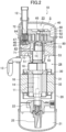
FIG. 2 is a vertical sectional view illustrating a configuration of a scroll compressor. -
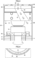
FIG. 3 is a cross-sectional side view illustrating a configuration of a discharge flow path. -
FIG. 4 is a cross-sectional plan view illustrating the configuration of the discharge flow path. -
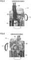
FIG. 5 is a diagram according to a comparative example, illustrating a flow of the refrigerant in a second space as viewed from a side closer to a discharge flow path. -
FIG. 6 is a diagram according to the comparative example, illustrating a flow of the refrigerant in the second space as viewed from a side opposite to the discharge flow path. -
FIG. 7 is a diagram according to the first embodiment, illustrating a flow of the refrigerant in a second space as viewed from a side closer to the discharge flow path. -
FIG. 8 is a diagram according to the first embodiment, illustrating a flow of the refrigerant in the second space as viewed from a side opposite to the discharge flow path. -
FIG. 9 is a cross-sectional side view illustrating a configuration of a discharge flow path in a scroll compressor according to a second embodiment. -
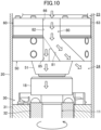
FIG. 10 is a cross-sectional side view illustrating a configuration of a discharge flow path in a scroll compressor according to a third embodiment. -
FIG. 11 is a cross-sectional side view illustrating a configuration of a discharge flow path in a scroll compressor according to a fourth embodiment. -
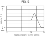
FIG. 12 is a graph showing the relationship between the position of a point P on a first surface and the angle α. -
FIG. 13 is a cross-sectional side view illustrating a configuration of a discharge flow path in a scroll compressor according to a fifth embodiment. -
FIG. 14 is a cross-sectional side view illustrating a configuration of a discharge flow path according to a first variation. -
FIG. 15 is a cross-sectional side view illustrating a configuration of a discharge flow path according to a second variation. - As illustrated in
FIG. 1 , a scroll compressor (10) serving as a rotary compressor is provided in a refrigeration apparatus (1). The refrigeration apparatus (1) includes a refrigerant circuit (1a) filled with a refrigerant. The refrigerant circuit (1a) includes the scroll compressor (10), a radiator (3), a decompression mechanism (4), and an evaporator (5). The decompression mechanism (4) is, for example, an expansion valve. The refrigerant circuit (1a) performs a vapor compression refrigeration cycle. - The refrigeration apparatus (1) is an air conditioner. The air conditioner may be a cooling-only apparatus, a heating-only apparatus, or an air conditioner switchable between cooling and heating. In this case, the air conditioner has a switching mechanism (e.g., a four-way switching valve) configured to switch the direction of circulation of the refrigerant. The refrigeration apparatus (1) may be a water heater, a chiller unit, or a cooling apparatus configured to cool air in an internal space. The cooling apparatus cools the air in a refrigerator, a freezer, or a container, for example.
- As illustrated in
FIG. 2 , the scroll compressor (10) includes a casing (20), a motor (30), and a compression mechanism (40). The casing (20) has a vertically oriented cylindrical shape, and is configured as a closed dome. The casing (20) houses therein the motor (30) and the compression mechanism (40). - The motor (30) includes a stator (31) and a rotor (32). The stator (31) is fixed to the inner circumferential surface of the casing (20). The rotor (32) is disposed inside the stator (31). A drive shaft (11) passes through the rotor (32). The rotor (32) is fixed to the drive shaft (11). The drive shaft (11) is provided with a balance weight (18).
- The casing (20) has, at its bottom, an oil reservoir (21). The oil reservoir (21) stores a lubricant. A suction pipe (12) is connected to an upper portion of the casing (20). A discharge pipe (13) is connected to a barrel of the casing (20).
- A housing (50) serving as a partitioning member is fixed to the casing (20). The housing (50) is made of a casting. The housing (50) is fixed to the inside of the casing (20) by, for example, shrink fitting. The housing (50) is located above the motor (30). The compression mechanism (40) is located above the housing (50). The discharge pipe (13) has an inflow end between the motor (30) and the housing (50).
- The interior of the casing (20) has a first space (23) and a second space (24) partitioned by the housing (50). The first space (23) is a space above the housing (50). The high-pressure refrigerant compressed by the compression mechanism (40) is discharged to the first space (23). The second space (24) is a space provided between the housing (50) and the motor (30). As will be described in detail later, the housing (50) has a discharge flow path (80) through which the refrigerant is discharged from the first space (23) toward the second space (24) (see
FIG. 3 ). - The housing (50) has a recess (53). The recess (53) is a recessed portion of the upper surface of the housing (50). An upper bearing (51) is located below the recess (53). The upper bearing (51) rotatably supports the drive shaft (11).
- The drive shaft (11) extends vertically along the center axis of the casing (20). The drive shaft (11) has a main shaft portion (14) and an eccentric portion (15).
- The eccentric portion (15) is provided at an upper end of the main shaft portion (14). The main shaft portion (14) has a lower portion rotatably supported by a lower bearing (22). The lower bearing (22) is fixed to the inner circumferential surface of the casing (20). The lower bearing (22) is provided with a positive-displacement pump (25), for example. The main shaft portion (14) has an upper portion passing through the housing (50) and rotatably supported by the upper bearing (51) of the housing (50).
- The compression mechanism (40) includes a fixed scroll (60) and a movable scroll (70). The fixed scroll (60) is fixed to the upper surface of the housing (50). The movable scroll (70) is arranged between the fixed scroll (60) and the housing (50).
- The fixed scroll (60) includes a fixed end plate (61), a fixed wrap (62), and an outer circumferential wall (63). The outer circumferential wall (63) is substantially tubular. The outer circumferential wall (63) is erected at the outer edge of the front surface (the lower surface in
FIG. 2 ) of the fixed end plate (61). - The fixed wrap (62) is spiral. The fixed wrap (62) is erected on a portion of the fixed end plate (61) inside the outer circumferential wall (63).
- The fixed end plate (61) is located on the outer circumference and is continuous with the fixed wrap (62). The end surface of the fixed wrap (62) and the end surface of the outer circumferential wall (63) are substantially flush with each other. The fixed scroll (60) is fixed to the housing (50).
- As will be described in detail later, the outer circumferential wall (63) of the fixed scroll (60) has a fixed flow path (66) communicating with the discharge flow path (80) of the housing (50) (see
FIG. 3 ). - The movable scroll (70) includes a movable end plate (71), a movable wrap (72), and a boss (73). The movable wrap (72) is spiral. The movable wrap (72) is formed on the upper surface of the movable end plate (71). The movable wrap (72) meshes with the fixed wrap (62).
- The boss (73) is formed on a central portion of the lower surface of the movable end plate (71). The eccentric portion (15) of the drive shaft (11) is inserted into the boss (73), whereby the boss (73) is connected to the drive shaft (11).
- An Oldham coupling (45) is provided at an upper portion of the housing (50). The Oldham coupling (45) blocks the rotation of the movable scroll (70) on its axis. The Oldham coupling (45) is provided with a key (46). The key (46) protrudes toward the lower surface of the movable end plate (71) of the movable scroll (70). The lower surface of the movable end plate (71) of the movable scroll (70) has a keyway (47). The key (46) of the Oldham coupling (45) is slidably fitted to the keyway (47).
- Although not shown, a key is provided in a portion of the Oldham coupling (45) toward the housing (50). The key toward the housing (50) is slidably fitted to a keyway (not shown) of the housing (50).
- The compression mechanism (40) has a fluid chamber (S) into which the refrigerant flows. The fluid chamber (S) is formed between the fixed scroll (60) and the movable scroll (70). The movable scroll (70) is placed so that the movable wrap (72) meshes with the fixed wrap (62) of the fixed scroll (60). Here, the lower surface of the outer circumferential wall (63) of the fixed scroll (60) serves as a facing surface that faces the movable scroll (70). On the other hand, the upper surface of the movable end plate (71) of the movable scroll (70) serves as a facing surface that faces the fixed scroll (60).
- The outer circumferential wall (63) of the fixed scroll (60) has a suction port (64). The suction port (64) is open near the winding end of the fixed wrap (62). A downstream end of the suction pipe (12) is connected to the suction port (64).
- The fixed end plate (61) of the fixed scroll (60) has, at its center, an outlet (65). The outlet (65) is open to the upper surface of the fixed end plate (61) of the fixed scroll (60). The high-pressure refrigerant discharged from the outlet (65) is discharged into the first space (23) above the housing (50). The refrigerant discharged into the first space (23) is discharged to the second space (24) through the fixed flow path (66) of the fixed scroll (60) and the discharge flow path (80) of the housing (50) (see
FIG. 3 ). - An oil supply passage (16) is formed inside the drive shaft (11). The oil supply passage (16) extends vertically from the lower end to the upper end of the drive shaft (11). The pump (25) is connected to the lower end of the drive shaft (11). A lower end portion of the pump (25) is immersed in the oil reservoir (21). The pump (25) sucks up the lubricant from the oil reservoir (21) as the drive shaft (11) rotates, and transfers the lubricant to the oil supply passage (16). The oil supply passage (16) supplies the lubricant in the oil reservoir (21) to the sliding surfaces between the lower bearing (22) and the drive shaft (11) and the sliding surfaces between the upper bearing (51) and the drive shaft (11), and to the sliding surfaces between the boss (73) and the drive shaft (11). The oil supply passage (16) is open to the upper end surface of the drive shaft (11) and supplies the lubricant to above the drive shaft (11).
- The recess (53) of the housing (50) communicates with the oil supply passage (16) of the drive shaft (11) via the inside of the boss (73) of the movable scroll (70). The high-pressure lubricant is supplied to the recess (53), so that a high pressure equivalent to the discharge pressure of the compression mechanism (40) acts on the recess (53). The movable scroll (70) is pressed onto the fixed scroll (60) by the high pressure that acts on the recess (53).
- As illustrated in
FIG. 3 , a fixed flow path (66) is provided in a side surface of the fixed scroll (60). The fixed flow path (66) is formed between a recessed portion of the side surface of the fixed scroll (60) and the inner circumferential surface of the casing (20). The fixed flow path (66) extends in the axial direction. - As illustrated also in
FIG. 4 , the discharge flow path (80) is provided in a side surface of the housing (50). The discharge flow path (80) is formed between a recessed portion of the side surface of the housing (50) and the inner circumferential surface of the casing (20). The upstream end of the discharge flow path (80) communicates with the downstream end of the fixed flow path (66) of the fixed scroll (60). The downstream end of the discharge flow path (80) communicates with the second space (24). - The discharge flow path (80) includes an inclined flow path (81). The inclined flow path (81) extends while inclining toward downstream in the direction of rotation of the motor (30). In the example illustrated in
FIG. 3 , the rotor (32) of the motor (30) rotates counterclockwise as viewed from above the casing (20). The inclined flow path (81) is inclined diagonally downward to the right of the housing (50). - In the example illustrated in
FIG. 3 , the inclined flow path (81) is a so-called "divergent" flow path having a downstream portion whose flow path width is greater than the flow path width of its upstream portion. The inclined flow path (81) may have a constant flow path width from the upstream side to the downstream side. - The high-pressure refrigerant discharged from the outlet (65) of the compression mechanism (40) into the first space (23) is discharged into the second space (24) via the fixed flow path (66) of the fixed scroll (60) and the discharge flow path (80) of the housing (50). The refrigerant passing through the discharge flow path (80) flows along the direction of inclination of the inclined flow path (81). Thus, when discharged into the second space (24), the refrigerant flows toward downstream in the direction of rotation of the motor (30).
- The housing (50) is made of a casting. The housing (50) made of a casting is subjected to surface finishing by machining. At this time, a casting surface is left in at least part of the discharge flow path (80).
- Increasing the surface area by leaving the casting surface in at least part of the discharge flow path (80) makes the lubricant contained in the refrigerant more likely to come into contact with the casting surface and form drops of oil, which makes it possible to improve the efficiency of separation of the lubricant.
- The results of simulation of the flow of the refrigerant in the second space (24) will be described below. First, a comparative example in which a discharge flow path (80) does not incline and extends along the axial direction will be described with reference to
FIGS. 5 and 6 . The flow of the refrigerant in the discharge flow path (80) and the second space (24) is indicated by white arrows. - As illustrated in
FIG. 5 , the refrigerant that has passed through the discharge flow path (80) is discharged into the second space (24), and then collides with the motor (30). As a result, the flow of the refrigerant branches into a clockwise flow and a counterclockwise flow as viewed from above the casing (20). The refrigerant that has collided with the motor (30) swirls while moving diagonally upward along the circumferential direction of the casing (20). - As illustrated in
FIG. 6 , the flow of the refrigerant swirling in the clockwise direction and the flow of the refrigerant swirling in the counterclockwise direction collide with each other in the second space (24) to generate a turbulent flow. This worsens the efficiency of separation of the lubricant. - In contrast, in this embodiment, as illustrated in
FIG. 7 , the refrigerant passing through the discharge flow path (80) flows along the direction of inclination of the inclined flow path (81). The refrigerant that has passed through the discharge flow path (80) is discharged into the second space (24), and then swirls along the inner circumferential surface of the casing (20) in the circumferential direction. - As illustrated also in
FIG. 8 , the refrigerant flows in the second space (24) while swirling only in one direction (counterclockwise as viewed from above the casing (20)). Here, the motor (30) rotates counterclockwise as viewed from above the casing (20), and the refrigerant swirls toward downstream in the direction of rotation of the motor (30). It is thus possible to cause smooth swirling of the refrigerant along the circumferential direction of the casing (20) in the second space (24) and improve the efficiency of separation of the lubricant. - According to a feature of this embodiment, the housing (50) serving as the partitioning member has the discharge flow path (80) through which the refrigerant is discharged from the first space (23) into the second space (24). The discharge flow path (80) includes the inclined flow path (81) that extends while inclining toward downstream in the direction of rotation of the motor (30).
- Thus, making the refrigerant flow along the inclined flow path (81) generates the flow of the refrigerant swirling along the circumferential direction of the casing (20) in the second space (24), which makes it possible to separate the lubricant contained in the refrigerant. Separation of the lubricant from the refrigerant can reduce oil loss.
- It is possible to generate the flow of the refrigerant swirling along the circumferential direction of the casing (20) by simply providing the discharge flow path (80) in the housing (50). This eliminates the need to provide a gas guide separately, which is necessary in known art. The component cost can thus be reduced. In addition, a process of spot-welding a gas guide to the casing (20) is not needed, resulting in a reduction in the number of operation processes.
- The absence of a gas guide in the second space (24) prevents interference of the gas guide with the flow of the refrigerant, making it possible for the refrigerant to swirl smoothly along the circumferential direction of the casing (20).
- According to a feature of this embodiment, increasing the surface area by leaving the casting surface in at least part of the discharge flow path (80) makes the lubricant contained in the refrigerant more likely to come into contact with the casting surface and form drops of oil, which makes it possible to improve the efficiency of separation of the lubricant.
- According to a feature of this embodiment, the refrigeration apparatus (1) includes the rotary compressor (10) and the refrigerant circuit (1a) through which the refrigerant compressed by the rotary compressor (10) flows. A refrigeration apparatus including the rotary compressor (10) can thus be provided.
- In the following description, the same reference characters designate the same components as those of the first embodiment, and the description is focused only on the difference.
- As illustrated in
FIG. 9 , the discharge flow path (80) is provided in a side surface of the housing (50). The discharge flow path (80) includes an inclined flow path (81) and an axial flow path (82). The inclined flow path (81) extends while inclining toward downstream in the direction of rotation of the motor (30). The axial flow path (82) is continuous with the upstream side of the inclined flow path (81), and extends along the axial direction of the motor (30). The joint portion between the axial flow path (82) and the inclined flow path (81) is curved. - In the example illustrated in
FIG. 9 , the positions of the upstream end and the downstream end of the discharge flow path (80) are set to be the same as those of the discharge flow path (80) of the first embodiment. The height of the housing (50) is equal to the height of the housing (50) of the first embodiment. - Thus, the upstream end of the inclined flow path (81) is positioned lower than in the case of the first embodiment by the length of the axial flow path (82) of the discharge flow path (80), which makes the angle of inclination of the inclined flow path (81) acute.
- Thus, the refrigerant that has flowed from the first space (23) and passed through the axial flow path (82) and the inclined flow path (81) of the discharge flow path (80) flows toward downstream in the direction of rotation of the motor (30) at an angle at which the refrigerant is less likely to collide with the motor (30) when discharged into the second space (24).
- According to a feature of this embodiment, providing the inclined flow path (81) to be continuous with the axial flow path (82) makes it possible for the inclined flow path (81) to have an acute angle of inclination as compared to a case where no axial flow path (82) is provided. Thus, the refrigerant can swirl along the circumferential direction of the casing (20) in the second space (24) easily.
- The refrigerant flowing along the axial flow path (82) collides with the inclined flow path (81), which causes the lubricant contained in the refrigerant to be separated in the inclined flow path (81) and then the refrigerant to flow down along the inclined flow path (81). This facilitates the separation of the refrigerant and the lubricant from each other.
- According to a feature of this embodiment, the joint portion between the axial flow path (82) and the inclined flow path (81) is curved. Thus, the refrigerant flowing from the axial flow path (82) to the inclined flow path (81) can flow smoothly along the curved flow path.
- As illustrated in
FIG. 10 , the discharge flow path (80) is provided in a side surface of the housing (50). The discharge flow path (80) includes an inclined flow path (81), an axial flow path (82), and a branch flow path (85). The inclined flow path (81) extends while inclining toward downstream in the direction of rotation of the motor (30). The axial flow path (82) is continuous with the upstream side of the inclined flow path (81), and extends along the axial direction of the motor (30). The joint portion between the axial flow path (82) and the inclined flow path (81) is curved. - The branch flow path (85) is continuous with the downstream side of the axial flow path (82), and extends along the axial direction of the motor (30). The branch flow path (85) branches toward the motor (30). The flow path cross-sectional area of the inclined flow path (81) is larger than the flow path cross-sectional area of the branch flow path (85).
- As can be seen, the discharge flow path (80) is branched into the inclined flow path (81) and the branch flow path (85) on the downstream side of the axial flow path (82). The refrigerant flowing from the first space (23) and passing through the axial flow path (82) of the discharge flow path (80) is divided into the inclined flow path (81) and the branch flow path (85). The refrigerant flowing through the inclined flow path (81) swirls in the circumferential direction in the second space (24) along the inner circumferential surface of the casing (20). The refrigerant flowing through the branch flow path (85) is discharged toward the motor (30) in the second space (24) to cool the motor (30).
- According to a feature of this embodiment, the refrigerant flowing through the branch flow path (85) toward the motor (30) can cool the motor (30).
- According to a feature of this embodiment, the flow path cross-sectional area of the inclined flow path (81) is larger than the flow path cross-sectional area of the branch flow path (85). Setting the amount of the refrigerant flowing through the inclined flow path (81) to be larger than the amount of the refrigerant flowing through the branch flow path (85) makes it possible to cool the motor (30) while ensuring sufficient flow of the refrigerant swirling along the circumferential direction of the casing (20).
- As illustrated in
FIG. 11 , the discharge flow path (80) is provided in a side surface of the housing (50). The discharge flow path (80) includes an inclined flow path (81) and an axial flow path (82). The inclined flow path (81) extends while inclining toward downstream in the direction of rotation of the motor (30). The axial flow path (82) is continuous with the upstream side of the inclined flow path (81), and extends along the axial direction of the motor (30). - The inclined flow path (81) has a first surface (81a) and a second surface (81b). The first surface (81a) is a surface with which the refrigerant that has flowed from the first space (23) collides and guides the refrigerant toward the second space (24). The second surface (81b) faces the first surface (81a).
- The inclined flow path (81) includes a first flow path (83) and a second flow path (84). The first flow path (83) has a substantially constant flow path width between the first surface (81a) and the second surface (81b). Here, the downstream end of the first flow path (83) on the first surface (81a) is referred to as a "downstream end (P3)." The second flow path (84) is continuous with the downstream side of the first flow path (83). The flow path width of the second flow path (84) is greater than the flow path width of the first flow path (83).
- It is preferable that the flow path cross-sectional area of the inclined flow path (81) is largest at the downstream end of the second flow path (84), but is not limited thereto. For example, an intermediate portion of the second flow path (84) may have the largest flow path cross-sectional area. In this case, it is preferable that the flow path cross-sectional area of the downstream end of the second flow path (84) is larger than or equal to the flow path cross-sectional area of the first flow path (83).
- The downstream end (P1) of the first surface (81a) is closer to the second space (24) than the downstream end (P4) of the second surface (81b) as viewed in the axial direction of the motor (30).
- Here, the angle formed between a phantom plane (91) passing through any point (P) on the first surface (81a) and extending along the first surface (81a) and a reference phantom plane (95) orthogonal to the axial direction of the motor (30) is referred to as an "angle α."
- The angle formed between a phantom plane (91) passing through the downstream end (P1) of the first surface (81a) and extending along the first surface (81a) and a reference phantom plane (95) orthogonal to the axial direction of the motor (30), i.e., the angle α at the point (P) located at the downstream end (P1) of the first surface (81a), is referred to as a "first angle α1."
- The angle formed between a phantom plane (91) passing through the upstream end (P2) of the first surface (81a) and extending along the first surface (81a) and a reference phantom plane (95) orthogonal to the axial direction of the motor (30), i.e., the angle α at the point (P) located at the upstream end (P2) of the first surface (81a), is referred to as a "second angle α2."
- In the example illustrated in
FIG. 11 , the shape of the inclined flow path (81) is determined so that the first angle α1 and the second angle α2 satisfy the condition "α1 ≤ α2." - Specifically, in the example illustrated in
FIG. 12 , the angle α at the point (P) on the first surface (81a) is substantially constant, i.e., the second angle α2, in the section from the upstream end (P2) of the first surface (81a) to the downstream end (P3) of the first flow path (83) on the first surface (81a). - The flow path width of the second flow path (84) increases downstream of the downstream end (P3) of the first flow path (83) on the first surface (81a). Thus, the angle α at the point (P) on the first surface (81a) is greater than the second angle α2. Then the angle α decreases gradually in the section up to the downstream end (P1) of the first surface (81a), and eventually becomes substantially constant at the first angle α1 that is smaller than the second angle α2.
- According to a feature of this embodiment, the shape of the inclined flow path (81) is determined so that the first angle α1 and the second angle α2 satisfy the above-described condition. Thus, the refrigerant flowing along the inclined flow path (81) is blown out easily in the direction orthogonal to the axial direction of the motor (30) in the second space (24). It is thus possible to promote the flow of the refrigerant in the second space (24) in the direction in which the refrigerant swirls easily along the circumferential direction of the casing (20).
- According to a feature of this embodiment, increasing the flow path width of a downstream portion of the inclined flow path (81) allows the refrigerant to flow smoothly from the inclined flow path (81) toward the second space (24).
- As illustrated in
FIG. 13 , the discharge flow path (80) is provided in a side surface of the housing (50). The discharge flow path (80) includes an inclined flow path (81) and an axial flow path (82). The inclined flow path (81) extends while inclining toward downstream in the direction of rotation of the motor (30). The axial flow path (82) is continuous with the upstream side of the inclined flow path (81), and extends along the axial direction of the motor (30). - The inclined flow path (81) has a first surface (81a) and a second surface (81b). The first surface (81a) is a surface with which the refrigerant that has flowed from the first space (23) collides and guides the refrigerant toward the second space (24). The second surface (81b) faces the first surface (81a).
- The inclined flow path (81) includes a first flow path (83) and a second flow path (84). The first flow path (83) has a substantially constant flow path width between the first surface (81a) and the second surface (81b). The second flow path (84) is continuous with the downstream side of the first flow path (83). The flow path width of the second flow path (84) is greater than the flow path width of the first flow path (83).
- The downstream end (P3) of the first flow path (83) on the first surface (81a) is closer to the first space (23) than the downstream end (P4) of the second surface (81b) as viewed in the axial direction of the motor (30).
- The downstream end (P1) of the first surface (81a) is closer to the second space (24) than the downstream end (P4) of the second surface (81b) as viewed in the axial direction of the motor (30).
- Here, the angle formed between a phantom plane (91) passing through any point (P) on the first surface (81a) and extending along the first surface (81a) and a reference phantom plane (95) orthogonal to the axial direction of the motor (30) is referred to as an "angle α."
- The angle formed between a phantom plane (91) passing through the downstream end (P1) of the first surface (81a) and extending along the first surface (81a) and a reference phantom plane (95) orthogonal to the axial direction of the motor (30), i.e., the angle α at the point (P) located at the downstream end (P1) of the first surface (81a), is referred to as a "first angle α1."
- The angle formed between a phantom plane (91) passing through the upstream end (P2) of the first surface (81a) and extending along the first surface (81a) and a reference phantom plane (95) orthogonal to the axial direction of the motor (30), i.e., the angle α at the point (P) located at the upstream end (P2) of the first surface (81a), is referred to as a "second angle α2."
- In the example illustrated in
FIG. 13 , the shape of the inclined flow path (81) is determined so that the first angle α1 and the second angle α2 satisfy the condition "α1 ≤ α2." - According to a feature of this embodiment, expanding the portion where the flow path width of the inclined flow path (81) is increased allows the refrigerant to flow smoothly from the inclined flow path (81) toward the second space (24).
- The above-described embodiments may be modified as follows.
- In the description of the embodiments, the discharge flow path (80) is provided in the housing (50), but is not limited thereto. For example, as illustrated in
FIG. 14 , if the housing (50) is not fixed to the inner circumferential surface of the casing (20), and the fixed scroll (60) is fixed to the inner circumferential surface of the casing (20) to separate the first space (23) and the second space (24) from each other, the discharge flow path (80) may be provided in the fixed scroll (60) serving as a partitioning member. - In the description of the embodiments, the discharge flow path (80) is formed between a recessed portion of the side surface of the housing (50) and the inner peripheral surface of the casing (20), but is not limited thereto. For example, as illustrated in
FIG. 15 , a tubular flow path member (86) forming the discharge flow path (80) may be separately embedded in the recessed portion of the side surface of the housing (50) to form the discharge flow path (80) in the housing (50). - It will be understood that the embodiments and variations described above can be modified with various changes in form and details without departing from the spirit and scope of the claims. The elements according to embodiments, the variations thereof, and the other embodiments may be combined and replaced with each other. In addition, the expressions of "first," "second," "third," ... , in the specification and claims are used to distinguish the terms to which these expressions are given, and do not limit the number and order of the terms.
- As can be seen from the foregoing description, the present disclosure is useful for a rotary compressor and a refrigeration apparatus.
-
- 1
- Refrigeration Apparatus
- 1a
- Refrigerant Circuit
- 10
- Scroll Compressor (Rotary Compressor)
- 11
- Drive Shaft
- 20
- Casing
- 23
- First Space
- 24
- Second Space
- 30
- Motor
- 40
- Compression Mechanism
- 50
- Housing (Partitioning Member)
- 80
- Discharge Flow Path
- 81
- Inclined Flow Path
- 81a
- First Surface
- 81b
- Second Surface
- 82
- Axial Flow Path
- 83
- First Flow Path
- 84
- Second Flow Path
- 85
- Branch Flow Path
- 91
- Phantom Plane
- 95
- Reference Phantom Plane
- P
- Point
- P1
- Downstream End
- P2
- Upstream End
- P3
- Downstream End
- P4
- Downstream End
Claims (10)
- A rotary compressor including: a casing (20); a compression mechanism (40) housed inside the casing (20) and configured to compress a refrigerant; a drive shaft (11) configured to drive the compression mechanism (40); and a motor (30) configured to rotate the drive shaft (11), the rotary compressor comprising:a partitioning member (50) housed inside the casing (20), whereinthe partitioning member (50) partitions an interior of the casing (20) into a first space (23) into which the refrigerant compressed by the compression mechanism (40) is discharged and a second space (24) provided between the partitioning member (50) and the motor (30),the partitioning member (50) has a discharge flow path (80) through which the refrigerant is discharged from the first space (23) to the second space (24), andthe discharge flow path (80) includes an inclined flow path (81) that extends while inclining toward downstream in a direction of rotation of the motor (30).
- The rotary compressor of claim 1, wherein
the discharge flow path (80) includes an axial flow path (82) that is continuous with an upstream side of the inclined flow path (81) and extends along an axial direction of the motor (30). - The rotary compressor of claim 2, wherein
a joint portion between the axial flow path (82) and the inclined flow path (81) is curved. - The rotary compressor of any one of claims 1 to 3, wherein
the discharge flow path (80) includes a branch flow path (85) that branches toward the motor (30). - The rotary compressor of claim 4, wherein
a flow path cross-sectional area of the inclined flow path (81) is larger than a flow path cross-sectional area of the branch flow path (85). - The rotary compressor of any one of claims 1 to 5, whereinthe partitioning member (50) is made of a casting, andat least part of the discharge flow path (80) has a casting surface.
- The rotary compressor of any one of claims 1 to 6, whereinthe inclined flow path (81) has a first surface (81a) with which the refrigerant that has flowed from the first space (23) collides and which guides the refrigerant toward the second space (24), and a second surface (81b) facing the first surface (81a),a downstream end (P1) of the first surface (81a) is closer to the second space (24) than a downstream end (P4) of the second surface (81b) as viewed in an axial direction of the motor (30), andan angle formed between a phantom plane (91) passing through any point (P) on the first surface (81a) and extending along the first surface (81a) and a reference phantom plane (95) orthogonal to the axial direction of the motor (30) is referred to as an angle α, and a first angle α1 and a second angle α2 satisfy a condition of α1 ≤ α2, where the first angle α1 is the angle α at the point (P) located at a downstream end (P1) of the first surface (81a), and the second angle α2 is the angle α at the point (P) located at an upstream end (P2) of the first surface (81a).
- The rotary compressor of claim 7, wherein
the inclined flow path (81) has a first flow path (83) having a substantially constant flow path width between the first surface (81a) and the second surface (81b), and a second flow path (84) that is continuous with a downstream side of the first flow path (83) and has a greater flow path width than the first flow path (83). - The rotary compressor of claim 8, wherein
a downstream end (P3) of the first flow path (83) on the first surface (81a) is closer to the first space (23) than a downstream end (P4) of the second surface (81b) as viewed in the axial direction of the motor (30). - A refrigeration apparatus comprising:the rotary compressor (10) of any one of claims 1 to 9; anda refrigerant circuit (1a) through which a refrigerant compressed by the rotary compressor (10) flows.
Applications Claiming Priority (2)
| Application Number | Priority Date | Filing Date | Title |
|---|---|---|---|
| JP2022045283 | 2022-03-22 | ||
| PCT/JP2023/008585 WO2023181915A1 (en) | 2022-03-22 | 2023-03-07 | Rotary compressor and refrigeration apparatus |
Publications (3)
| Publication Number | Publication Date |
|---|---|
| EP4474651A1 true EP4474651A1 (en) | 2024-12-11 |
| EP4474651A4 EP4474651A4 (en) | 2025-05-07 |
| EP4474651B1 EP4474651B1 (en) | 2026-03-25 |
Family
ID=88100773
Family Applications (1)
| Application Number | Title | Priority Date | Filing Date |
|---|---|---|---|
| EP23774514.6A Active EP4474651B1 (en) | 2022-03-22 | 2023-03-07 | Rotary compressor and refrigeration apparatus |
Country Status (5)
| Country | Link |
|---|---|
| US (1) | US20250012492A1 (en) |
| EP (1) | EP4474651B1 (en) |
| JP (2) | JP7425380B2 (en) |
| CN (1) | CN118715374A (en) |
| WO (1) | WO2023181915A1 (en) |
Family Cites Families (10)
| Publication number | Priority date | Publication date | Assignee | Title |
|---|---|---|---|---|
| JPS57212389A (en) * | 1981-06-22 | 1982-12-27 | Hitachi Ltd | Enclosed scroll compressor |
| JPS60162084A (en) * | 1984-01-31 | 1985-08-23 | Matsushita Electric Ind Co Ltd | Oil separator for rotary compressor |
| JP3391072B2 (en) * | 1993-12-28 | 2003-03-31 | 松下電器産業株式会社 | Hermetic scroll compressor |
| JPH1089277A (en) * | 1996-09-17 | 1998-04-07 | Daikin Ind Ltd | Compressor |
| JP3750048B2 (en) * | 2000-05-22 | 2006-03-01 | 株式会社日立製作所 | Scroll compressor |
| JP4261999B2 (en) * | 2003-06-27 | 2009-05-13 | 東芝キヤリア株式会社 | Horizontal hermetic compressor |
| JP5050543B2 (en) * | 2007-01-31 | 2012-10-17 | ダイキン工業株式会社 | Hermetic compressor |
| JP5120387B2 (en) * | 2010-01-20 | 2013-01-16 | ダイキン工業株式会社 | Compressor |
| JP5429319B2 (en) | 2012-03-30 | 2014-02-26 | ダイキン工業株式会社 | Compressor |
| JP2021063453A (en) * | 2019-10-11 | 2021-04-22 | ダイキン工業株式会社 | Compressor |
-
2023
- 2023-03-07 WO PCT/JP2023/008585 patent/WO2023181915A1/en not_active Ceased
- 2023-03-07 CN CN202380020980.9A patent/CN118715374A/en active Pending
- 2023-03-07 EP EP23774514.6A patent/EP4474651B1/en active Active
- 2023-03-07 JP JP2023034355A patent/JP7425380B2/en active Active
- 2023-11-14 JP JP2023193738A patent/JP2024012590A/en active Pending
-
2024
- 2024-09-17 US US18/887,900 patent/US20250012492A1/en not_active Abandoned
Also Published As
| Publication number | Publication date |
|---|---|
| CN118715374A (en) | 2024-09-27 |
| US20250012492A1 (en) | 2025-01-09 |
| JP2023140305A (en) | 2023-10-04 |
| EP4474651B1 (en) | 2026-03-25 |
| WO2023181915A1 (en) | 2023-09-28 |
| JP2024012590A (en) | 2024-01-30 |
| EP4474651A4 (en) | 2025-05-07 |
| JP7425380B2 (en) | 2024-01-31 |
Similar Documents
| Publication | Publication Date | Title |
|---|---|---|
| US7462021B2 (en) | Rotary compressor, and car air conditioner and heat pump type water heater using the compressor | |
| US11248604B2 (en) | Scroll compressor and refrigeration cycle apparatus | |
| WO2010010790A1 (en) | Horizontal scroll compressor | |
| CN114787518B (en) | compressor | |
| CN113167266A (en) | Compressor and air conditioner | |
| EP4474651B1 (en) | Rotary compressor and refrigeration apparatus | |
| US12006934B2 (en) | Scroll compressor and refrigeration cycle apparatus | |
| US12571394B2 (en) | Scroll compressor with blocking part for oil separation | |
| JP7119812B2 (en) | compressor | |
| EP3985256B1 (en) | Scroll compressor | |
| CN112585357B (en) | Hermetic compressor | |
| EP4459128A1 (en) | Rotary compressor and refrigeration apparatus | |
| EP4372229B1 (en) | Scroll compressor and refrigeration apparatus | |
| EP4729783A1 (en) | Rotary compressor and refrigeration apparatus | |
| EP3919742A1 (en) | Scroll compressor | |
| JP2023000256A (en) | Compressor with oil recovery device | |
| EP4656881A1 (en) | Rotary compressor and refrigeration apparatus | |
| JP2024013789A (en) | Rotary compressor and refrigeration equipment | |
| JP2024112223A (en) | Compressor | |
| JP2011085039A (en) | High pressure hermetic compressor | |
| JP2008014245A (en) | Compressor | |
| JP2013224594A (en) | Compressor |
Legal Events
| Date | Code | Title | Description |
|---|---|---|---|
| STAA | Information on the status of an ep patent application or granted ep patent |
Free format text: STATUS: THE INTERNATIONAL PUBLICATION HAS BEEN MADE |
|
| PUAI | Public reference made under article 153(3) epc to a published international application that has entered the european phase |
Free format text: ORIGINAL CODE: 0009012 |
|
| STAA | Information on the status of an ep patent application or granted ep patent |
Free format text: STATUS: REQUEST FOR EXAMINATION WAS MADE |
|
| 17P | Request for examination filed |
Effective date: 20240904 |
|
| AK | Designated contracting states |
Kind code of ref document: A1 Designated state(s): AL AT BE BG CH CY CZ DE DK EE ES FI FR GB GR HR HU IE IS IT LI LT LU LV MC ME MK MT NL NO PL PT RO RS SE SI SK SM TR |
|
| P01 | Opt-out of the competence of the unified patent court (upc) registered |
Free format text: CASE NUMBER: APP_930/2025 Effective date: 20250108 |
|
| A4 | Supplementary search report drawn up and despatched |
Effective date: 20250407 |
|
| RIC1 | Information provided on ipc code assigned before grant |
Ipc: F04C 29/04 20060101ALI20250401BHEP Ipc: F04C 23/00 20060101ALI20250401BHEP Ipc: F04C 18/02 20060101ALI20250401BHEP Ipc: F04B 39/02 20060101ALI20250401BHEP Ipc: F04C 29/02 20060101AFI20250401BHEP |
|
| DAV | Request for validation of the european patent (deleted) | ||
| DAX | Request for extension of the european patent (deleted) | ||
| GRAP | Despatch of communication of intention to grant a patent |
Free format text: ORIGINAL CODE: EPIDOSNIGR1 |
|
| STAA | Information on the status of an ep patent application or granted ep patent |
Free format text: STATUS: GRANT OF PATENT IS INTENDED |
|
| INTG | Intention to grant announced |
Effective date: 20251124 |
|
| GRAS | Grant fee paid |
Free format text: ORIGINAL CODE: EPIDOSNIGR3 |
|
| GRAA | (expected) grant |
Free format text: ORIGINAL CODE: 0009210 |
|
| STAA | Information on the status of an ep patent application or granted ep patent |
Free format text: STATUS: THE PATENT HAS BEEN GRANTED |
|
| AK | Designated contracting states |
Kind code of ref document: B1 Designated state(s): AL AT BE BG CH CY CZ DE DK EE ES FI FR GB GR HR HU IE IS IT LI LT LU LV MC ME MK MT NL NO PL PT RO RS SE SI SK SM TR |
|
| REG | Reference to a national code |
Ref country code: CH Ref legal event code: F10 Free format text: ST27 STATUS EVENT CODE: U-0-0-F10-F00 (AS PROVIDED BY THE NATIONAL OFFICE) Effective date: 20260325 Ref country code: GB Ref legal event code: FG4D |
|
| REG | Reference to a national code |
Ref country code: DE Ref legal event code: R096 Ref document number: 602023014194 Country of ref document: DE |
|
| REG | Reference to a national code |
Ref country code: IE Ref legal event code: FG4D |