EP4474650A1 - Screw pump and its components - Google Patents
Screw pump and its components Download PDFInfo
- Publication number
- EP4474650A1 EP4474650A1 EP24176065.1A EP24176065A EP4474650A1 EP 4474650 A1 EP4474650 A1 EP 4474650A1 EP 24176065 A EP24176065 A EP 24176065A EP 4474650 A1 EP4474650 A1 EP 4474650A1
- Authority
- EP
- European Patent Office
- Prior art keywords
- screw
- insert
- lubricated
- screw pump
- screws
- Prior art date
- Legal status (The legal status is an assumption and is not a legal conclusion. Google has not performed a legal analysis and makes no representation as to the accuracy of the status listed.)
- Granted
Links
Images




Classifications
-
- F—MECHANICAL ENGINEERING; LIGHTING; HEATING; WEAPONS; BLASTING
- F04—POSITIVE - DISPLACEMENT MACHINES FOR LIQUIDS; PUMPS FOR LIQUIDS OR ELASTIC FLUIDS
- F04C—ROTARY-PISTON, OR OSCILLATING-PISTON, POSITIVE-DISPLACEMENT MACHINES FOR LIQUIDS; ROTARY-PISTON, OR OSCILLATING-PISTON, POSITIVE-DISPLACEMENT PUMPS
- F04C2/00—Rotary-piston machines or pumps
- F04C2/08—Rotary-piston machines or pumps of intermeshing-engagement type, i.e. with engagement of co-operating members similar to that of toothed gearing
- F04C2/12—Rotary-piston machines or pumps of intermeshing-engagement type, i.e. with engagement of co-operating members similar to that of toothed gearing of other than internal-axis type
- F04C2/14—Rotary-piston machines or pumps of intermeshing-engagement type, i.e. with engagement of co-operating members similar to that of toothed gearing of other than internal-axis type with toothed rotary pistons
- F04C2/16—Rotary-piston machines or pumps of intermeshing-engagement type, i.e. with engagement of co-operating members similar to that of toothed gearing of other than internal-axis type with toothed rotary pistons with helical teeth, e.g. chevron-shaped, screw type
- F04C2/165—Rotary-piston machines or pumps of intermeshing-engagement type, i.e. with engagement of co-operating members similar to that of toothed gearing of other than internal-axis type with toothed rotary pistons with helical teeth, e.g. chevron-shaped, screw type having more than two rotary pistons with parallel axes
-
- F—MECHANICAL ENGINEERING; LIGHTING; HEATING; WEAPONS; BLASTING
- F04—POSITIVE - DISPLACEMENT MACHINES FOR LIQUIDS; PUMPS FOR LIQUIDS OR ELASTIC FLUIDS
- F04C—ROTARY-PISTON, OR OSCILLATING-PISTON, POSITIVE-DISPLACEMENT MACHINES FOR LIQUIDS; ROTARY-PISTON, OR OSCILLATING-PISTON, POSITIVE-DISPLACEMENT PUMPS
- F04C2/00—Rotary-piston machines or pumps
- F04C2/08—Rotary-piston machines or pumps of intermeshing-engagement type, i.e. with engagement of co-operating members similar to that of toothed gearing
- F04C2/12—Rotary-piston machines or pumps of intermeshing-engagement type, i.e. with engagement of co-operating members similar to that of toothed gearing of other than internal-axis type
- F04C2/14—Rotary-piston machines or pumps of intermeshing-engagement type, i.e. with engagement of co-operating members similar to that of toothed gearing of other than internal-axis type with toothed rotary pistons
- F04C2/16—Rotary-piston machines or pumps of intermeshing-engagement type, i.e. with engagement of co-operating members similar to that of toothed gearing of other than internal-axis type with toothed rotary pistons with helical teeth, e.g. chevron-shaped, screw type
-
- F—MECHANICAL ENGINEERING; LIGHTING; HEATING; WEAPONS; BLASTING
- F04—POSITIVE - DISPLACEMENT MACHINES FOR LIQUIDS; PUMPS FOR LIQUIDS OR ELASTIC FLUIDS
- F04C—ROTARY-PISTON, OR OSCILLATING-PISTON, POSITIVE-DISPLACEMENT MACHINES FOR LIQUIDS; ROTARY-PISTON, OR OSCILLATING-PISTON, POSITIVE-DISPLACEMENT PUMPS
- F04C2/00—Rotary-piston machines or pumps
- F04C2/08—Rotary-piston machines or pumps of intermeshing-engagement type, i.e. with engagement of co-operating members similar to that of toothed gearing
- F04C2/12—Rotary-piston machines or pumps of intermeshing-engagement type, i.e. with engagement of co-operating members similar to that of toothed gearing of other than internal-axis type
- F04C2/14—Rotary-piston machines or pumps of intermeshing-engagement type, i.e. with engagement of co-operating members similar to that of toothed gearing of other than internal-axis type with toothed rotary pistons
- F04C2/18—Rotary-piston machines or pumps of intermeshing-engagement type, i.e. with engagement of co-operating members similar to that of toothed gearing of other than internal-axis type with toothed rotary pistons with similar tooth forms
-
- F—MECHANICAL ENGINEERING; LIGHTING; HEATING; WEAPONS; BLASTING
- F04—POSITIVE - DISPLACEMENT MACHINES FOR LIQUIDS; PUMPS FOR LIQUIDS OR ELASTIC FLUIDS
- F04C—ROTARY-PISTON, OR OSCILLATING-PISTON, POSITIVE-DISPLACEMENT MACHINES FOR LIQUIDS; ROTARY-PISTON, OR OSCILLATING-PISTON, POSITIVE-DISPLACEMENT PUMPS
- F04C15/00—Component parts, details or accessories of machines, pumps or pumping installations, not provided for in groups F04C2/00 - F04C14/00
- F04C15/0088—Lubrication
-
- F—MECHANICAL ENGINEERING; LIGHTING; HEATING; WEAPONS; BLASTING
- F04—POSITIVE - DISPLACEMENT MACHINES FOR LIQUIDS; PUMPS FOR LIQUIDS OR ELASTIC FLUIDS
- F04C—ROTARY-PISTON, OR OSCILLATING-PISTON, POSITIVE-DISPLACEMENT MACHINES FOR LIQUIDS; ROTARY-PISTON, OR OSCILLATING-PISTON, POSITIVE-DISPLACEMENT PUMPS
- F04C18/00—Rotary-piston pumps specially adapted for elastic fluids
- F04C18/08—Rotary-piston pumps specially adapted for elastic fluids of intermeshing-engagement type, i.e. with engagement of co-operating members similar to that of toothed gearing
- F04C18/12—Rotary-piston pumps specially adapted for elastic fluids of intermeshing-engagement type, i.e. with engagement of co-operating members similar to that of toothed gearing of other than internal-axis type
- F04C18/14—Rotary-piston pumps specially adapted for elastic fluids of intermeshing-engagement type, i.e. with engagement of co-operating members similar to that of toothed gearing of other than internal-axis type with toothed rotary pistons
- F04C18/16—Rotary-piston pumps specially adapted for elastic fluids of intermeshing-engagement type, i.e. with engagement of co-operating members similar to that of toothed gearing of other than internal-axis type with toothed rotary pistons with helical teeth, e.g. chevron-shaped, screw type
-
- F—MECHANICAL ENGINEERING; LIGHTING; HEATING; WEAPONS; BLASTING
- F04—POSITIVE - DISPLACEMENT MACHINES FOR LIQUIDS; PUMPS FOR LIQUIDS OR ELASTIC FLUIDS
- F04C—ROTARY-PISTON, OR OSCILLATING-PISTON, POSITIVE-DISPLACEMENT MACHINES FOR LIQUIDS; ROTARY-PISTON, OR OSCILLATING-PISTON, POSITIVE-DISPLACEMENT PUMPS
- F04C2230/00—Manufacture
- F04C2230/20—Manufacture essentially without removing material
- F04C2230/21—Manufacture essentially without removing material by casting
-
- F—MECHANICAL ENGINEERING; LIGHTING; HEATING; WEAPONS; BLASTING
- F04—POSITIVE - DISPLACEMENT MACHINES FOR LIQUIDS; PUMPS FOR LIQUIDS OR ELASTIC FLUIDS
- F04C—ROTARY-PISTON, OR OSCILLATING-PISTON, POSITIVE-DISPLACEMENT MACHINES FOR LIQUIDS; ROTARY-PISTON, OR OSCILLATING-PISTON, POSITIVE-DISPLACEMENT PUMPS
- F04C2240/00—Components
- F04C2240/20—Rotors
-
- F—MECHANICAL ENGINEERING; LIGHTING; HEATING; WEAPONS; BLASTING
- F04—POSITIVE - DISPLACEMENT MACHINES FOR LIQUIDS; PUMPS FOR LIQUIDS OR ELASTIC FLUIDS
- F04C—ROTARY-PISTON, OR OSCILLATING-PISTON, POSITIVE-DISPLACEMENT MACHINES FOR LIQUIDS; ROTARY-PISTON, OR OSCILLATING-PISTON, POSITIVE-DISPLACEMENT PUMPS
- F04C2240/00—Components
- F04C2240/30—Casings or housings
-
- F—MECHANICAL ENGINEERING; LIGHTING; HEATING; WEAPONS; BLASTING
- F05—INDEXING SCHEMES RELATING TO ENGINES OR PUMPS IN VARIOUS SUBCLASSES OF CLASSES F01-F04
- F05C—INDEXING SCHEME RELATING TO MATERIALS, MATERIAL PROPERTIES OR MATERIAL CHARACTERISTICS FOR MACHINES, ENGINES OR PUMPS OTHER THAN NON-POSITIVE-DISPLACEMENT MACHINES OR ENGINES
- F05C2203/00—Non-metallic inorganic materials
- F05C2203/02—Glass
-
- F—MECHANICAL ENGINEERING; LIGHTING; HEATING; WEAPONS; BLASTING
- F05—INDEXING SCHEMES RELATING TO ENGINES OR PUMPS IN VARIOUS SUBCLASSES OF CLASSES F01-F04
- F05C—INDEXING SCHEME RELATING TO MATERIALS, MATERIAL PROPERTIES OR MATERIAL CHARACTERISTICS FOR MACHINES, ENGINES OR PUMPS OTHER THAN NON-POSITIVE-DISPLACEMENT MACHINES OR ENGINES
- F05C2225/00—Synthetic polymers, e.g. plastics; Rubber
-
- F—MECHANICAL ENGINEERING; LIGHTING; HEATING; WEAPONS; BLASTING
- F05—INDEXING SCHEMES RELATING TO ENGINES OR PUMPS IN VARIOUS SUBCLASSES OF CLASSES F01-F04
- F05C—INDEXING SCHEME RELATING TO MATERIALS, MATERIAL PROPERTIES OR MATERIAL CHARACTERISTICS FOR MACHINES, ENGINES OR PUMPS OTHER THAN NON-POSITIVE-DISPLACEMENT MACHINES OR ENGINES
- F05C2225/00—Synthetic polymers, e.g. plastics; Rubber
- F05C2225/04—PTFE [PolyTetraFluorEthylene]
-
- F—MECHANICAL ENGINEERING; LIGHTING; HEATING; WEAPONS; BLASTING
- F05—INDEXING SCHEMES RELATING TO ENGINES OR PUMPS IN VARIOUS SUBCLASSES OF CLASSES F01-F04
- F05C—INDEXING SCHEME RELATING TO MATERIALS, MATERIAL PROPERTIES OR MATERIAL CHARACTERISTICS FOR MACHINES, ENGINES OR PUMPS OTHER THAN NON-POSITIVE-DISPLACEMENT MACHINES OR ENGINES
- F05C2251/00—Material properties
- F05C2251/14—Self lubricating materials; Solid lubricants
-
- F—MECHANICAL ENGINEERING; LIGHTING; HEATING; WEAPONS; BLASTING
- F05—INDEXING SCHEMES RELATING TO ENGINES OR PUMPS IN VARIOUS SUBCLASSES OF CLASSES F01-F04
- F05C—INDEXING SCHEME RELATING TO MATERIALS, MATERIAL PROPERTIES OR MATERIAL CHARACTERISTICS FOR MACHINES, ENGINES OR PUMPS OTHER THAN NON-POSITIVE-DISPLACEMENT MACHINES OR ENGINES
- F05C2253/00—Other material characteristics; Treatment of material
- F05C2253/04—Composite, e.g. fibre-reinforced
-
- F—MECHANICAL ENGINEERING; LIGHTING; HEATING; WEAPONS; BLASTING
- F05—INDEXING SCHEMES RELATING TO ENGINES OR PUMPS IN VARIOUS SUBCLASSES OF CLASSES F01-F04
- F05C—INDEXING SCHEME RELATING TO MATERIALS, MATERIAL PROPERTIES OR MATERIAL CHARACTERISTICS FOR MACHINES, ENGINES OR PUMPS OTHER THAN NON-POSITIVE-DISPLACEMENT MACHINES OR ENGINES
- F05C2253/00—Other material characteristics; Treatment of material
- F05C2253/16—Fibres
Definitions
- the disclosure relates to the field of screw pumps and their components. More specifically, but not exclusively, this disclosure also relates to a cooling circuit, for example for a vehicle, that comprises the screw pump.
- Known screw pumps comprise a casing and two, three or more screws housed in the casing, which are driven by a motor to force fluid flow through the pump.
- the disclosure aims to improve the known designs of screw pumps and their performance.
- the disclosure relates to a screw pump comprising: a casing with an inlet, an outlet and a flow chamber between the inlet and the outlet, and at least two screws housed in the flow chamber to force a fluid flow through the flow chamber from the inlet to the outlet, wherein at least one of the screws comprises a lubricated polymer material.
- the inventors have determined that forming at least one of the screws from a lubricated polymer material provides a surprising improvement to the performance of the screw pump.
- the two or more screws may comprise at least one drive screw and at least one driven screw.
- the at least one screw comprising a lubricated polymer material may comprise at least one drive screw.
- the at least one screw comprising a lubricated polymer material may comprise at least one driven screw.
- At least one of the screws may comprise a polyphenylene sulfide material, which may but need not be lubricated.
- the lubricated polymer material may comprise polyphenylene sulfide.
- the lubricated polymer material may comprise a lubricant, for example a solid lubricant or a dry lubricant.
- the lubricant may comprise one of polytetrafluorethylene (PTFE), molybdenum disulfide and carbon or graphite.
- some, but not all, of the screws may comprise a lubricated polymer material.
- Some, but not all, of the screws may comprise a polyphenylene sulfide material, which may but need not be lubricated.
- the lubricated polymer material may comprise a lubricant, for example a solid lubricant or a dry lubricant.
- the lubricant may comprise one of polytetrafluorethylene (PTFE), molybdenum disulfide and carbon or graphite.
- the at least one drive screw comprises a lubricated polymer material, for example a solid lubricant or a dry lubricant, whilst the at least one driven screw may be devoid of lubricant or at least devoid of a solid lubricant or a dry lubricant.
- At least two of the screws may comprise a lubricated polymer material.
- the screw pump comprises three or more screws, some but not all of them may comprise a lubricated polymer material. In other examples, all of the screws comprise a lubricated polymer material.
- the at least one drive screw and the at least one driven screw may both comprise a lubricated polymer material, for example a solid lubricant or a dry lubricant.
- the at least one drive screw may comprise a first lubricant and/or the at least one driven screw may comprise a second lubricant.
- Each of the first and second lubricants may comprise one of polytetrafluorethylene (PTFE), molybdenum disulfide and carbon or graphite.
- the second lubricant may be a different lubricant from the first lubricant.
- Each of the first and second lubricants may comprise a different one of polytetrafluorethylene (PTFE), molybdenum disulfide and carbon or graphite.
- the drive screw may comprise a different concentration of lubricant, e.g. of the same lubricant, relative to the at least one driven screw.
- At least two of the screws may comprise a polyphenylene sulfide material, which may but need not be lubricated.
- the screw pump comprises three or more screws, some but not all of them may comprise a polyphenylene sulfide material, which may but need not be lubricated.
- the lubricated polymer material may be filled, for example with fibers such as glass fibers.
- the lubricated polymer material may be reinforced, for example with fibers such as glass fibers.
- the lubricated polymer material may comprise a fiber reinforced lubricated polymer material.
- the fibers may comprise glass.
- the fiber reinforced lubricated polymer material may comprise a glass fiber reinforced lubricated polymer material.
- the polyphenylene sulfide material may comprise a fiber reinforced polyphenylene sulfide material which may, but need not be lubricated.
- the fibers may comprise glass.
- the fiber reinforced polyphenylene sulfide material may comprise glass fiber reinforced polyphenylene sulfide material.
- the at least one drive screw comprises a fiber reinforced lubricated polymer material, for example a fiber reinforced lubricated polyphenylene sulfide material, and the at least one driven screw may be devoid of fibers and/or lubricant.
- the casing can comprise a shell within which an insert defining the flow chamber is housed.
- the insert may comprise a polymer material, which may be lubricated.
- the disclosure also relates to an insert for a screw pump as described above.
- the insert may define a flow chamber for receiving and housing at least two screws.
- the insert may comprise or be formed of a lubricated polymer material.
- the disclosure also relates to an insert for a screw pump, the insert defining a flow chamber for receiving and housing at least two screws, wherein the insert comprises or is formed of a lubricated polymer material.
- the disclosure also relates to a casing for a screw pump, e.g. a screw pump as described above, the casing comprising or being formed of a lubricated polymer material and defining a flow chamber for receiving and housing at least two screws.
- the disclosure also relates to a casing for a screw pump, e.g. a screw pump as described above, the casing comprising a shell within which an insert is housed, wherein the insert comprises or is formed of a lubricated polymer material and defines a flow chamber for receiving and housing at least two screws.
- At least part of the casing may comprise a polyphenylene sulfide material.
- the polymer material may be filled, for example with fibers such as glass fibers.
- the polymer material may be reinforced, for example with fibers such as glass fibers.
- the polymer from which the casing, casing part or insert is formed may be lubricated.
- the casing, casing part or insert may comprise a lubricated polymer material.
- the lubricated polymer material may comprise polyphenylene sulfide.
- the casing, casing part or insert may comprise a polyphenylene sulfide material, which may but need not be lubricated.
- the casing, casing part or insert may comprise a fiber reinforced lubricated polymer material, which may comprise glass fibers.
- the casing, casing part or insert may comprise a glass fiber reinforced lubricated polymer material.
- the casing, casing part or insert may comprise a fiber reinforced polyphenylene sulfide material which may comprise glass fibers.
- the fiber reinforced polyphenylene sulfide material from which the insert is formed may, but need not be lubricated.
- the casing, casing part or insert may comprise a glass fiber reinforced polyphenylene sulfide (PPS) material.
- the at least one screw (e.g. the driven screw) comprises a lubricated polymer material, which need not be fiber reinforced, and the insert comprises a fiber reinforced lubricated polymer material.
- the insert comprises a fiber reinforced lubricated polymer material.
- the flow chamber can be defined by a tubular wall of the insert.
- the tubular wall can present, or can have, a substantially constant wall thickness.
- the tubular wall can have several cylindrical lobes, which can approximate the outer profile of the meshing screws.
- the cylindrical lobes can comprise a center lobe, for example which approximates the outer surfaces of a center drive screw.
- the cylindrical lobes can comprise an outer lobe on each side of the center lobe, for example which approximates the outer surfaces of a respective driven screw.
- the flow chamber can provide minimal space between the screws, while allowing them to rotate freely.
- the casing can comprise a space between the shell and the insert.
- the interface between the shell and the insert can be designed to allow, when in use, part of the circulating fluid to enter the space.
- the space can be separate from the flow chamber and/or not be part of it.
- the insert can comprise one or more anti-rotation protrusions, which can engage with the shell to inhibit relative rotation between them.
- the or each anti-rotation protrusion can extend axially from the insert.
- the or each anti-rotation protrusion can comprise an antirotation tab.
- the insert can comprise one or more anti-rotation protrusions extending from one or each of its ends.
- the insert can comprise a flange or clamp, such as a circular flange or clamp, at one end.
- the flange or clamp can have a perimeter which approximates an inner surface of the shell, for example to position the insert within the shell.
- At least one of the screws may have a center shaft made of a first material on which the screw is molded from a second material.
- first material and the second material can be materials that are distinct from each other or materials that are similar.
- the first and second materials can be different.
- the first material is stiffer than the second material, for example such that the at least one screw is reinforced.
- the first material can comprise a metal, for example steel such as stainless steel, or a stiff polymer.
- the second material can comprise a polymer, wherein case the first material can comprise a polymer that is stiffer than the polymer of the second material.
- the second material can be less stiff than the first material.
- At least one of the screws comprises a center shaft made of a first material on which the screw is molded from a second material that is less stiff than the first material.
- the first and second materials can be identical or similar.
- the first and second material can each comprise a polymer, for example a similar polymer.
- the first and second materials can comprise one or more polymers. At least one of the polymers can comprise PPS.
- the polymer, for example PPS can be filled, for example with fibers such as glass fibers.
- the polymer, for example PPS can be lubricated.
- the first and second materials can comprise the same polymer, for example PPS, which can be filled or additivated or neither differently for each of the first and second materials.
- the center shaft can comprise one or more anchoring features or elements or members.
- the anchoring feature or features can be embedded in the second material, for example to anchor the center shaft in the second material.
- the or each anchoring feature can comprise a rib or a spline, for example an axial rib or spline.
- the or each anchoring feature can extend along at least part of the center shaft.
- the anchoring feature or features can comprise at least two anchoring features, or at least two groups of anchoring features, that can be spaced along the length of the center shaft.
- the at least one reinforced screw can comprise a drive screw whose center shaft can comprise a motor coupling, for example to receive torque from a drive motor.
- the disclosure also relates to a method of manufacturing a screw for a screw pump, the method comprising: providing a center shaft made of a first material, and molding a screw on the center shaft using a second, lubricated polymer material.
- first material and the second material can be materials that are distinct from each other or materials that are similar.
- the first and second materials can be different.
- the method can comprise: inserting the center shaft into the mold before the screw is molded on it.
- the first material is stiffer than the second material, for example such that the at least one screw is reinforced.
- the first material can comprise a metal or a stiff polymer.
- the second material can be less stiff than the first material.
- the first and second materials can be similar.
- the first and second materials can comprise a polymer.
- the method can comprise: molding the center shaft using the first material, for example before molding the screw on the center shaft using the second material.
- the method can comprise a two-step molding process.
- the pump can comprise a flexible coupling.
- the flexible coupling can be connected to one of the screws to couple the screw to a drive motor.
- the flexible coupling can be connected to the motor coupling of the center shaft of the drive screw.
- the flexible coupling can comprise a first side or end, for example with a first coupling feature to engage a shaft of a drive motor.
- the flexible coupling can comprise a second side or end, for example with a second coupling feature engaging a cooperating feature of the screw to which it is connected.
- the first coupling feature can be a slot, which can be diametrical and/or which can be designed to house a protrusion on a shaft of the or of a drive motor.
- the second coupling feature can be a protrusion, for example to engage in a cooperating feature of the drive screw.
- the protrusion can be rectangular.
- the second coupling feature can be rotationally offset, for example by 90 degrees, relative to the first coupling feature.
- the flexible coupling can comprise a polymer material, which can be lubricated, for example in its mass and/or by greasing.
- At least one of the screws can be non-self-locking.
- the at least one screw can comprise one or more threads each having a pitch and/or a diameter and/or a configuration that enables it to be ejected from a mold by applying an axial force to it, for example without applying a rotational force to it.
- the at least one screw can comprise one or more threads each having a helix angle that enables them to be ejected from a mold by applying an axial force to it, for example without applying a rotational force to it.
- the helix angle can be at least 60°, for example at least 70°.
- the at least one screw can be made of a polymer, for example polyphenylene sulfide (PPS).
- PPS polyphenylene sulfide
- the polymer, for example PPS can be filled, for example with fibers such as glass fibers.
- the polymer, for example PPS can be lubricated.
- the disclosure also relates to a method of manufacturing a screw for a screw pump, the method comprising molding a screw in a molding tool using a lubricated polymer material and ejecting the screw from the mold by applying an axial force to it, wherein the material and threads of the screw are configured such that the axial force causes the screw to rotate freely in the mold.
- the screw's self-locking can be inhibited by its configuration, in particular the helix angle of the thread or of each of the threads and/or the coefficient of friction between the thread or threads and the surfaces of the mold.
- the disclosure also relates to a screw pump comprising: a casing with an inlet, an outlet and a flow chamber between the inlet and the outlet, and at least two screws housed in the flow chamber to force a fluid flow through the flow chamber from the inlet to the outlet, wherein at least one of the screws can be obtained by the method described above.
- At least one of the screws can be self-locking.
- the at least one screw can comprise one or more threads each having a pitch and/or a diameter and/or a configuration that prevents it from being ejected from a mold by applying an axial force to the latter, for example without applying a rotational force to the latter.
- the at least one screw can comprise one or more threads each having a helix angle that prevents them from being ejected from a mold by applying an axial force to the latter, for example without applying a rotational force to the latter.
- the helix angle can be less than 60°.
- the at least one screw can be made of a polymer, for example polyphenylene sulfide (PPS).
- PPS polyphenylene sulfide
- the polymer, for example PPS can be filled, for example with fibers such as glass fibers.
- the polymer, for example PPS can be lubricated.
- At least one screw comprises a release coupling to restrict the rotation of the screw when it is being extracted from a molding tool.
- each screw comprises a release coupling to restrict the rotation of the screw when it is being extracted from a molding tool.
- At least one or each screw for example the or each self-locking screw, can comprise a release coupling.
- the release coupling can be used to restrict the rotation of the screw when it is being extracted from a molding tool.
- the insert can comprise at least one recess.
- the or each recess can be designed to house one of the release couplings, for example when the screws are housed in the flow chamber.
- One of the release couplings can be housed inside the recess.
- the screws can comprise three or more screws, or four or more screws.
- the screws can comprise at least one drive screw and at least one driven screw, for example at least two driven screws.
- the screws can comprise at least three driven screws, which can be distributed, for example evenly, around the drive screw.
- At least one of the driven screws may comprise a lubricated polymer material, which need not be fiber reinforced, and the at least one drive screw comprises a fiber reinforced lubricated polymer material.
- the drive screw may comprise the center shaft made of the first material on which the screw is molded from the second material.
- the second material may comprise the fiber reinforced lubricated polymer material.
- the or each driven screw may be devoid of a center shaft formed of a different material.
- the or each driven screw may be formed only of a lubricated polymer material, which need not be fiber reinforced.
- the disclosure also relates to a method of manufacturing a screw for a screw pump, the method comprising molding a screw in a molding tool using a lubricated polymer material and ejecting the screw from the mold by applying torque to a screw release coupling while unscrewing the screw from the mold.
- the release coupling of at least one of the screws can comprise at least one radial shoulder.
- the release coupling of at least one of the screws can comprise a circular or non-circular structure.
- the release coupling of at least one of the screws can comprise an annular or partially annular structure.
- the disclosure also relates to a cooling circuit for a vehicle comprising a screw pump as described above.
- a screw pump assembly 1 which comprises a motor 10 coupled to a screw pump 2 by a flexible coupling 11.
- the screw pump 2 comprises a casing 3 with an inlet pipe 30, an outlet pipe 31 and a flow chamber 32 between the inlet 30 and the outlet 31.
- Three screws 4, 5, 6 are housed in the flow chamber 32 to force fluid flow through the flow chamber 32 from the inlet 30 to the outlet 31.
- at least one of the screws 4, 5, 6 comprises a lubricated polymer material.
- all of the screws comprise a polyphenylene sulfide (PPS) material containing a solid or dry lubricant, such as polytetrafluorethylene (PTFE), molybdenum disulfide and carbon or graphite.
- PPS polyphenylene sulfide
- PTFE polytetrafluorethylene
- carbon or graphite carbon or graphite
- the casing 3 comprises a shell 33 within which an insert 34 defining the flow chamber 32 is housed.
- the insert 34 also comprises a lubricated polymer material, specifically a glass fiber reinforced PPS material containing a solid or dry lubricant, such as polytetrafluorethylene (PTFE), molybdenum disulfide and carbon or graphite.
- PTFE polytetrafluorethylene
- the shell 33 is in the shape of a hollow cylinder with a closed end 33a from which the inlet pipe 30 protrudes.
- the outlet pipe 31 radially protrudes from the shell 33, next to an open end 33b.
- the screw pump 2 is reversible and, as such, the inlet pipe 30 and the outlet pipe 31 can be reversed by rotating the screw pump 2 in the opposite direction.
- the axial pipe 30 protruding from the closed end 33a will hereinafter be referred to as the inlet pipe 30 and the radial pipe 30 protruding from the open end 33b will hereinafter be referred to as the outlet pipe 31.
- the flow chamber 32 is defined by a tubular wall 35 of the insert 34, which has a substantially constant wall thickness.
- the tubular wall 35 has three cylindrical lobes 35a, 35b, 35c which approximate the outer profile of the three meshing screws 4, 5, 6. More specifically, a center lobe 35a approximates the outer surfaces of a center drive screw 4, with an outer lobe 35b, 35c on each side of the center lobe 35a, each approximating the outer surfaces of a respective driven screw 5, 6.
- the flow chamber 32 provides minimal space between the screws 4, 5, 6, while allowing them to rotate freely.
- the insert 34 also comprises a pair of anti-rotation tabs 36, 37 protruding axially from each of its ends.
- a first pair of anti-rotation tabs 36 protrudes from the upper and lower parts of the center lobe 35a at a first end of the insert 34.
- a second pair of anti-rotation tabs 37 protrudes from a circular flange 38, above and below the center lobe 35a at a second end of the insert 34.
- the circular flange 38 has a perimeter which approximates an inner surface of the shell 33, which makes it possible to position the insert 34 within the shell 33 and to create a space E between them, as more clearly shown in Figure 5 .
- the casing 3 also comprises a pair of mounting discs 39a, 39b and a spacing interface 39c.
- the mounting discs 39a, 39b engage the anti-rotation tabs 36, 37 of the insert 34 and are attached inside the shell 33 to trap the screws 4, 5, 6 and the insert 34 between them.
- the spacing interface 39c sealingly closes the screw pump 2 and isolates the flow chamber 32 from the motor 10, but the interface between the shell 33 and the insert 34 is designed to allow, when in use, part of the circulating fluid to enter the space E.
- the first mounting disc 39a can be part of or integrated with the spacing interface 39c.
- the second mounting disc 39b can be part of or integrated with the insert 34. When the second mounting disc 39b is part of the insert 34, the antirotation tabs protruding from the circular flange 38 can be omitted.
- the flexible coupling 11 is substantially cylindrical and has a first coupling feature 12 at a first of its axial ends and a second coupling feature 13 at a second of its axial ends.
- the first coupling feature 12 is a diametrical slot for designed to house a rectangular protrusion on a shaft of the drive motor 10.
- the second coupling feature 13 is a rectangular protrusion, which is rotationally offset by 90 degrees from the first coupling feature 12, to engage a cooperating feature of the drive screw 4.
- the flexible coupling 11 is made of a lubricated polymer.
- the use of a flexible coupling between the drive motor 10 and the screw pump 2 makes it possible to accommodate minor angular and axial misalignment, while minimizing vibrations.
- This feature acts in synergy with the vibration damping effect of the space E between the shell 33 and the insert 34.
- the drive screw 4 is more clearly shown in Figure 7 , and comprises a center shaft 40 and a body 41 molded on the center shaft 40.
- the body 41 comprises two diametrically opposite threads 42 along its length.
- the center shaft 40 comprises anchoring features 43 embedded in the body 41 to anchor the center shaft 40 to the body 41.
- the anchoring features 43 comprise two groups of axial splines 44 that extend along part of the center shaft 40.
- the two groups of axial splines 44 are spaced apart from one another along the length of the center shaft 40.
- the center shaft 40 also comprises a motor coupling 45 in the form of a diametrical slot designed to house the rectangular protrusion 13 of the flexible coupling 11, although it can directly house the rectangular protrusion of the shaft of the drive motor 10.
- the center shaft 40 is made of stainless steel and the body 41 is made of a lubricated polymer material, specifically a glass fiber reinforced PPS material containing a solid or dry lubricant, such as polytetrafluorethylene (PTFE), molybdenum disulfide and carbon or graphite.
- PTFE polytetrafluorethylene
- FIGS 9 and 10 show the driven screws 5 and 6.
- Each driven screw 5, 6 comprises a lubricated polymer material, specifically a PPS material that is devoid of fiber reinforcement containing a solid or dry lubricant, such as polytetrafluorethylene (PTFE), molybdenum disulfide and carbon or graphite.
- PTFE polytetrafluorethylene
- the type and/or concentration of the lubricant in the driven screws 5, 6 may be different to that of the body 41 of the drive screw 4 and/or different to that of the insert 34.
- Each driven screw 5, 6 comprises a respective body 50, 60 with a pair of diametrically opposite threads 51, 61 along its length.
- Each driven screw 5, 6 also comprises a release coupling 52, 62 at one of its ends.
- Each release coupling 52, 62 is in the shape of a ring 53, 63 with a pair of notches 54, 64 aligned with the adjacent ends of the threads 51, 61.
- the notches 54, 64 form radial shoulders 54a, 64a to which torque can be applied.
- each driven screw 5, 6 The diameter of the ring 53, 63 of each driven screw 5, 6 is larger than that of the threads 51, 61 and holes 55, 65 are defined between the ring 53, 63 and the base of the threads 51, 61. Thus, a fluid passage is defined along the entire length of each driven screw 5, 6, between the threads 51, 61 and through the release coupling 52, 62.
- Each driven screw 5, 6 also comprises an axial protrusion 56, 66 in the center of each of its ends.
- the threads 51, 61 of the driven screws 5, 6 are self-locking, in that their rotation is prevented if only an axial force is applied to the driven screws 5, 6 at the end of the molding cycle, while they are still in the mold cavity (not shown). As such, torque must be applied to the driven screws 5, 6 to remove them from the mold.
- the release coupling 52, 62 allows this torque to be applied to the driven screws 5, 6.
- the insert 34 comprises an annular step 32a, 32b surrounding the part of the flow chamber 32 defined by each of the outer lobes 35b, 35c.
- These annular steps 32a, 32b act as recesses that accommodate the rings 53, 63 when the screws 4, 5, 6 are housed in the flow chamber 32.
- screw threads 51, 61 can alternatively be designed to be non-self-locking.
- the release coupling 52, 62 can be omitted, and the driven screws 5, 6 can be ejected at the end of the molding process by simply applying axial force to them.
- the threads can each have a pitch and/or a diameter and/or a configuration that enables them to be ejected from a mold by applying an axial force to it, without applying a rotational force to it. More specifically, the threads can each have a helix angle that enables them to be ejected from a mold by applying an axial force to it, without applying a rotational force to it.
- the helix angle can be at least 60°, for example at least 70°, when the threads are made of a polymer, such as lubricated PPS.
- a screw pump assembly 101 according to a second example is shown, which is similar to the first example in that similar features are marked with like numbers incremented by 100.
- the screw pump assembly 1 in this example differs from that of the first example in that it comprises three driven screws 105, 106, 107 and that the drive screw has three threads 142, which is more clearly illustrated in Figure 15 .
- the tubular wall 135 has four cylindrical lobes 135a, 135b, 135c, 135d, which approximate the outer profile of the four meshing screws 104, 105, 106, 107. More specifically, the center lobe 135a approximates the outer surfaces of the center drive screw 104, with three outer lobes 135b, 135c, 135d evenly distributed around the perimeter of the center lobe 135a, each approximating the outer surfaces of a respective driven screw 105, 106, 107.
- Figure 16 shows another screw assembly 205, 206, 207 that can be used in the pump assembly in Figure 11 instead of the screw assembly in Figure 15 .
- the screws 205, 206, 207 are similar to the ones in the previous example in that similar features are marked by like numbers incremented by 100.
- the screw assembly 205, 206, 207 in this example differs from the one in the previous example in that the helix angle is greater.
Landscapes
- Engineering & Computer Science (AREA)
- Mechanical Engineering (AREA)
- General Engineering & Computer Science (AREA)
- Details And Applications Of Rotary Liquid Pumps (AREA)
- Rotary Pumps (AREA)
Abstract
Description
- The disclosure relates to the field of screw pumps and their components. More specifically, but not exclusively, this disclosure also relates to a cooling circuit, for example for a vehicle, that comprises the screw pump.
- Known screw pumps comprise a casing and two, three or more screws housed in the casing, which are driven by a motor to force fluid flow through the pump.
- The disclosure aims to improve the known designs of screw pumps and their performance.
- The disclosure relates to a screw pump comprising: a casing with an inlet, an outlet and a flow chamber between the inlet and the outlet, and at least two screws housed in the flow chamber to force a fluid flow through the flow chamber from the inlet to the outlet, wherein at least one of the screws comprises a lubricated polymer material.
- The inventors have determined that forming at least one of the screws from a lubricated polymer material provides a surprising improvement to the performance of the screw pump.
- The two or more screws may comprise at least one drive screw and at least one driven screw. The at least one screw comprising a lubricated polymer material may comprise at least one drive screw. The at least one screw comprising a lubricated polymer material may comprise at least one driven screw.
- At least one of the screws may comprise a polyphenylene sulfide material, which may but need not be lubricated. The lubricated polymer material may comprise polyphenylene sulfide. The lubricated polymer material may comprise a lubricant, for example a solid lubricant or a dry lubricant. The lubricant may comprise one of polytetrafluorethylene (PTFE), molybdenum disulfide and carbon or graphite.
- In some examples, some, but not all, of the screws may comprise a lubricated polymer material. Some, but not all, of the screws may comprise a polyphenylene sulfide material, which may but need not be lubricated. The lubricated polymer material may comprise a lubricant, for example a solid lubricant or a dry lubricant. The lubricant may comprise one of polytetrafluorethylene (PTFE), molybdenum disulfide and carbon or graphite.
- In some examples, the at least one drive screw comprises a lubricated polymer material, for example a solid lubricant or a dry lubricant, whilst the at least one driven screw may be devoid of lubricant or at least devoid of a solid lubricant or a dry lubricant.
- In some examples, at least two of the screws may comprise a lubricated polymer material. For example, where the screw pump comprises three or more screws, some but not all of them may comprise a lubricated polymer material. In other examples, all of the screws comprise a lubricated polymer material.
- The at least one drive screw and the at least one driven screw may both comprise a lubricated polymer material, for example a solid lubricant or a dry lubricant.
- The at least one drive screw may comprise a first lubricant and/or the at least one driven screw may comprise a second lubricant. Each of the first and second lubricants may comprise one of polytetrafluorethylene (PTFE), molybdenum disulfide and carbon or graphite.
- The second lubricant may be a different lubricant from the first lubricant. Each of the first and second lubricants may comprise a different one of polytetrafluorethylene (PTFE), molybdenum disulfide and carbon or graphite.
- The drive screw may comprise a different concentration of lubricant, e.g. of the same lubricant, relative to the at least one driven screw.
- In some examples, at least two of the screws may comprise a polyphenylene sulfide material, which may but need not be lubricated. For example, where the screw pump comprises three or more screws, some but not all of them may comprise a polyphenylene sulfide material, which may but need not be lubricated.
- The lubricated polymer material may be filled, for example with fibers such as glass fibers. The lubricated polymer material may be reinforced, for example with fibers such as glass fibers.
- The lubricated polymer material may comprise a fiber reinforced lubricated polymer material. The fibers may comprise glass. The fiber reinforced lubricated polymer material may comprise a glass fiber reinforced lubricated polymer material.
- The polyphenylene sulfide material may comprise a fiber reinforced polyphenylene sulfide material which may, but need not be lubricated. The fibers may comprise glass. The fiber reinforced polyphenylene sulfide material may comprise glass fiber reinforced polyphenylene sulfide material.
- In some examples, the at least one drive screw comprises a fiber reinforced lubricated polymer material, for example a fiber reinforced lubricated polyphenylene sulfide material, and the at least one driven screw may be devoid of fibers and/or lubricant.
- The casing can comprise a shell within which an insert defining the flow chamber is housed.
- The insert may comprise a polymer material, which may be lubricated.
- The disclosure also relates to an insert for a screw pump as described above. The insert may define a flow chamber for receiving and housing at least two screws. The insert may comprise or be formed of a lubricated polymer material.
- The disclosure also relates to an insert for a screw pump, the insert defining a flow chamber for receiving and housing at least two screws, wherein the insert comprises or is formed of a lubricated polymer material.
- The disclosure also relates to a casing for a screw pump, e.g. a screw pump as described above, the casing comprising or being formed of a lubricated polymer material and defining a flow chamber for receiving and housing at least two screws.
- The disclosure also relates to a casing for a screw pump, e.g. a screw pump as described above, the casing comprising a shell within which an insert is housed, wherein the insert comprises or is formed of a lubricated polymer material and defines a flow chamber for receiving and housing at least two screws.
- At least part of the casing, e.g. the insert, may comprise a polyphenylene sulfide material. The polymer material may be filled, for example with fibers such as glass fibers. The polymer material may be reinforced, for example with fibers such as glass fibers.
- The polymer from which the casing, casing part or insert is formed may be lubricated. The casing, casing part or insert may comprise a lubricated polymer material. The lubricated polymer material may comprise polyphenylene sulfide.
- The casing, casing part or insert may comprise a polyphenylene sulfide material, which may but need not be lubricated.
- The casing, casing part or insert may comprise a fiber reinforced lubricated polymer material, which may comprise glass fibers. The casing, casing part or insert may comprise a glass fiber reinforced lubricated polymer material.
- The casing, casing part or insert may comprise a fiber reinforced polyphenylene sulfide material which may comprise glass fibers. The fiber reinforced polyphenylene sulfide material from which the insert is formed may, but need not be lubricated. The casing, casing part or insert may comprise a glass fiber reinforced polyphenylene sulfide (PPS) material.
- In some examples, the at least one screw (e.g. the driven screw) comprises a lubricated polymer material, which need not be fiber reinforced, and the insert comprises a fiber reinforced lubricated polymer material. The skilled person will appreciate that this may be beneficial in some applications.
- The flow chamber can be defined by a tubular wall of the insert. The tubular wall can present, or can have, a substantially constant wall thickness. The tubular wall can have several cylindrical lobes, which can approximate the outer profile of the meshing screws. The cylindrical lobes can comprise a center lobe, for example which approximates the outer surfaces of a center drive screw. The cylindrical lobes can comprise an outer lobe on each side of the center lobe, for example which approximates the outer surfaces of a respective driven screw. The flow chamber can provide minimal space between the screws, while allowing them to rotate freely.
- The casing can comprise a space between the shell and the insert. The interface between the shell and the insert can be designed to allow, when in use, part of the circulating fluid to enter the space. The space can be separate from the flow chamber and/or not be part of it.
- The insert can comprise one or more anti-rotation protrusions, which can engage with the shell to inhibit relative rotation between them. The or each anti-rotation protrusion can extend axially from the insert. The or each anti-rotation protrusion can comprise an antirotation tab. The insert can comprise one or more anti-rotation protrusions extending from one or each of its ends. The insert can comprise a flange or clamp, such as a circular flange or clamp, at one end. The flange or clamp can have a perimeter which approximates an inner surface of the shell, for example to position the insert within the shell.
- At least one of the screws (e.g. the drive screw) may have a center shaft made of a first material on which the screw is molded from a second material.
- For the sake of clarity, the first material and the second material can be materials that are distinct from each other or materials that are similar.
- The first and second materials can be different. Advantageously, the first material is stiffer than the second material, for example such that the at least one screw is reinforced. The first material can comprise a metal, for example steel such as stainless steel, or a stiff polymer. The second material can comprise a polymer, wherein case the first material can comprise a polymer that is stiffer than the polymer of the second material. Thus, according to one aspect, the second material can be less stiff than the first material.
- According to one aspect of the disclosure, at least one of the screws comprises a center shaft made of a first material on which the screw is molded from a second material that is less stiff than the first material.
- As a variant, the first and second materials can be identical or similar. The first and second material can each comprise a polymer, for example a similar polymer.
- The first and second materials can comprise one or more polymers. At least one of the polymers can comprise PPS. The polymer, for example PPS, can be filled, for example with fibers such as glass fibers. The polymer, for example PPS, can be lubricated. The first and second materials can comprise the same polymer, for example PPS, which can be filled or additivated or neither differently for each of the first and second materials.
- The center shaft can comprise one or more anchoring features or elements or members. The anchoring feature or features can be embedded in the second material, for example to anchor the center shaft in the second material.
- The or each anchoring feature can comprise a rib or a spline, for example an axial rib or spline. The or each anchoring feature can extend along at least part of the center shaft.
- The anchoring feature or features can comprise at least two anchoring features, or at least two groups of anchoring features, that can be spaced along the length of the center shaft.
- The at least one reinforced screw can comprise a drive screw whose center shaft can comprise a motor coupling, for example to receive torque from a drive motor.
- The disclosure also relates to a method of manufacturing a screw for a screw pump, the method comprising: providing a center shaft made of a first material, and molding a screw on the center shaft using a second, lubricated polymer material.
- For the sake of clarity, the first material and the second material can be materials that are distinct from each other or materials that are similar.
- The first and second materials can be different. The method can comprise: inserting the center shaft into the mold before the screw is molded on it. Advantageously, the first material is stiffer than the second material, for example such that the at least one screw is reinforced. The first material can comprise a metal or a stiff polymer.
- Thus, according to one aspect, the second material can be less stiff than the first material.
- As a variant, the first and second materials can be similar. The first and second materials can comprise a polymer. The method can comprise: molding the center shaft using the first material, for example before molding the screw on the center shaft using the second material. The method can comprise a two-step molding process.
- The pump can comprise a flexible coupling. The flexible coupling can be connected to one of the screws to couple the screw to a drive motor. The flexible coupling can be connected to the motor coupling of the center shaft of the drive screw.
- The flexible coupling can comprise a first side or end, for example with a first coupling feature to engage a shaft of a drive motor. The flexible coupling can comprise a second side or end, for example with a second coupling feature engaging a cooperating feature of the screw to which it is connected.
- The first coupling feature can be a slot, which can be diametrical and/or which can be designed to house a protrusion on a shaft of the or of a drive motor. The second coupling feature can be a protrusion, for example to engage in a cooperating feature of the drive screw. The protrusion can be rectangular. The second coupling feature can be rotationally offset, for example by 90 degrees, relative to the first coupling feature.
- The flexible coupling can comprise a polymer material, which can be lubricated, for example in its mass and/or by greasing.
- At least one of the screws can be non-self-locking. The at least one screw can comprise one or more threads each having a pitch and/or a diameter and/or a configuration that enables it to be ejected from a mold by applying an axial force to it, for example without applying a rotational force to it. The at least one screw can comprise one or more threads each having a helix angle that enables them to be ejected from a mold by applying an axial force to it, for example without applying a rotational force to it.
- The helix angle can be at least 60°, for example at least 70°. The at least one screw can be made of a polymer, for example polyphenylene sulfide (PPS). The polymer, for example PPS, can be filled, for example with fibers such as glass fibers. The polymer, for example PPS, can be lubricated.
- The disclosure also relates to a method of manufacturing a screw for a screw pump, the method comprising molding a screw in a molding tool using a lubricated polymer material and ejecting the screw from the mold by applying an axial force to it, wherein the material and threads of the screw are configured such that the axial force causes the screw to rotate freely in the mold.
- The screw's self-locking can be inhibited by its configuration, in particular the helix angle of the thread or of each of the threads and/or the coefficient of friction between the thread or threads and the surfaces of the mold.
- The disclosure also relates to a screw pump comprising: a casing with an inlet, an outlet and a flow chamber between the inlet and the outlet, and at least two screws housed in the flow chamber to force a fluid flow through the flow chamber from the inlet to the outlet, wherein at least one of the screws can be obtained by the method described above.
- As a variant, at least one of the screws can be self-locking. The at least one screw can comprise one or more threads each having a pitch and/or a diameter and/or a configuration that prevents it from being ejected from a mold by applying an axial force to the latter, for example without applying a rotational force to the latter. The at least one screw can comprise one or more threads each having a helix angle that prevents them from being ejected from a mold by applying an axial force to the latter, for example without applying a rotational force to the latter.
- The helix angle can be less than 60°. The at least one screw can be made of a polymer, for example polyphenylene sulfide (PPS). The polymer, for example PPS, can be filled, for example with fibers such as glass fibers. The polymer, for example PPS, can be lubricated.
- According to one aspect of the disclosure, at least one screw comprises a release coupling to restrict the rotation of the screw when it is being extracted from a molding tool.
- According to one aspect of the disclosure, each screw comprises a release coupling to restrict the rotation of the screw when it is being extracted from a molding tool.
- Of course, according to different variants of the disclosure, at least one or each screw, for example the or each self-locking screw, can comprise a release coupling. The release coupling can be used to restrict the rotation of the screw when it is being extracted from a molding tool.
- The insert can comprise at least one recess. The or each recess can be designed to house one of the release couplings, for example when the screws are housed in the flow chamber. One of the release couplings can be housed inside the recess.
- In each of the aforementioned aspects of the disclosure, the screws can comprise three or more screws, or four or more screws. The screws can comprise at least one drive screw and at least one driven screw, for example at least two driven screws. Advantageously, the screws can comprise at least three driven screws, which can be distributed, for example evenly, around the drive screw.
- In some examples, at least one of the driven screws may comprise a lubricated polymer material, which need not be fiber reinforced, and the at least one drive screw comprises a fiber reinforced lubricated polymer material. In such examples, the drive screw may comprise the center shaft made of the first material on which the screw is molded from the second material. The second material may comprise the fiber reinforced lubricated polymer material. In such examples, the or each driven screw may be devoid of a center shaft formed of a different material. In such examples, the or each driven screw may be formed only of a lubricated polymer material, which need not be fiber reinforced.
- The disclosure also relates to a method of manufacturing a screw for a screw pump, the method comprising molding a screw in a molding tool using a lubricated polymer material and ejecting the screw from the mold by applying torque to a screw release coupling while unscrewing the screw from the mold.
- The release coupling of at least one of the screws can comprise at least one radial shoulder. The release coupling of at least one of the screws can comprise a circular or non-circular structure. The release coupling of at least one of the screws can comprise an annular or partially annular structure.
- The disclosure also relates to a cooling circuit for a vehicle comprising a screw pump as described above.
- For the avoidance of doubt, all the features described herein also apply to any aspect of the disclosure.
- As part of this application, it is expressly provided that the various aspects, embodiments, examples and alternatives disclosed in the preceding paragraphs and/or in the following description and drawings, and in particular the individual features thereof, can be taken separately or in any combination. In other words, all aspects and/or features of any aspect can be combined in any way, unless these features are incompatible.
- For the avoidance of doubt, the terms "can", "and/or", "for example", and any other similar term used herein must be interpreted as not limiting, such that any feature described herein is not necessarily required to be present. Indeed, any combination of optional features is expressly foreseen without departing from the scope of the disclosure.
- Other features and advantages of the disclosure will become apparent from the following detailed description, which will be understood in reference to the appended drawings, in which:
-
Figure 1 illustrates a pump assembly according to one aspect of the disclosure; -
Figure 2 is an exploded view of the pump assembly inFigure 1 ; -
Figure 3 illustrates a first side of the flow chamber insert of the pump assembly inFigures 1 and2 ; -
Figure 4 illustrates a second side of the flow chamber insert inFigure 3 ; -
Figure 5 illustrates the insert inFigures 3 and 4 housed in the shell of the casing and with the screws housed in the insert; -
Figure 6 illustrates the flexible coupling of the assembly inFigures 1 and2 , which couples the drive screw to the drive motor; -
Figure 7 illustrates the drive screw of the pump assembly inFigures 1 and2 ; -
Figure 8 illustrates the center shaft of the drive screw inFigure 7 ; -
Figure 9 illustrates a first side of the two driven screws of the pump assembly inFigures 1 and2 ; -
Figure 10 illustrates a second side of the driven screws inFigure 9 ; -
Figure 11 illustrates a pump assembly according to another aspect of the disclosure; -
Figure 12 illustrates a first side of the flow chamber insert of the pump assembly inFigure 11 ; -
Figure 13 illustrates a second side of the flow chamber insert inFigure 12 ; -
Figure 14 illustrates the insert inFigures 12 and13 housed in the shell of the casing and with the screws housed in the insert; -
Figure 15 illustrates the screw assembly of the pump assembly shown inFigure 11 ; and -
Figure 16 illustrates another screw assembly that can be used in the pump assembly inFigure 11 instead of the screw assembly inFigure 15 . - Different aspects of different aspects of the disclosure are described in more detail below, in reference to
Figures 1 to 16 appended hereto. - Referring now to
Figures 1 and2 , ascrew pump assembly 1 is shown, which comprises amotor 10 coupled to ascrew pump 2 by aflexible coupling 11. Thescrew pump 2 comprises acasing 3 with aninlet pipe 30, anoutlet pipe 31 and aflow chamber 32 between theinlet 30 and theoutlet 31. Threescrews flow chamber 32 to force fluid flow through theflow chamber 32 from theinlet 30 to theoutlet 31. Preferably, at least one of thescrews - The
casing 3 comprises ashell 33 within which aninsert 34 defining theflow chamber 32 is housed. In this example, theinsert 34 also comprises a lubricated polymer material, specifically a glass fiber reinforced PPS material containing a solid or dry lubricant, such as polytetrafluorethylene (PTFE), molybdenum disulfide and carbon or graphite. - The
shell 33 is in the shape of a hollow cylinder with aclosed end 33a from which theinlet pipe 30 protrudes. Theoutlet pipe 31 radially protrudes from theshell 33, next to anopen end 33b. Thescrew pump 2 is reversible and, as such, theinlet pipe 30 and theoutlet pipe 31 can be reversed by rotating thescrew pump 2 in the opposite direction. However, for the sake of simplicity, theaxial pipe 30 protruding from theclosed end 33a will hereinafter be referred to as theinlet pipe 30 and theradial pipe 30 protruding from theopen end 33b will hereinafter be referred to as theoutlet pipe 31. - As shown in
Figures 3 and 4 , theflow chamber 32 is defined by atubular wall 35 of theinsert 34, which has a substantially constant wall thickness. Thetubular wall 35 has threecylindrical lobes screws center lobe 35a approximates the outer surfaces of acenter drive screw 4, with anouter lobe center lobe 35a, each approximating the outer surfaces of a respective drivenscrew flow chamber 32 provides minimal space between thescrews - The
insert 34 also comprises a pair ofanti-rotation tabs anti-rotation tabs 36 protrudes from the upper and lower parts of thecenter lobe 35a at a first end of theinsert 34. A second pair ofanti-rotation tabs 37 protrudes from acircular flange 38, above and below thecenter lobe 35a at a second end of theinsert 34. Thecircular flange 38 has a perimeter which approximates an inner surface of theshell 33, which makes it possible to position theinsert 34 within theshell 33 and to create a space E between them, as more clearly shown inFigure 5 . - The
casing 3 also comprises a pair of mountingdiscs spacing interface 39c. The mountingdiscs anti-rotation tabs insert 34 and are attached inside theshell 33 to trap thescrews insert 34 between them. Thespacing interface 39c sealingly closes thescrew pump 2 and isolates theflow chamber 32 from themotor 10, but the interface between theshell 33 and theinsert 34 is designed to allow, when in use, part of the circulating fluid to enter the space E. - In some examples, the
first mounting disc 39a can be part of or integrated with thespacing interface 39c. In some examples, thesecond mounting disc 39b can be part of or integrated with theinsert 34. When thesecond mounting disc 39b is part of theinsert 34, the antirotation tabs protruding from thecircular flange 38 can be omitted. - The presence of a space E between the
shell 33 and theinsert 34, which is filled with circulating fluid, provides a vibration-damping effect resulting from the interaction betweenscrews separate insert 34 makes it possible to manufacture theflow chamber 32 with great precision. - This also makes it easier to manufacture the
insert 34 by injection molding, since it can be designed with a substantially constant wall thickness to optimize cycle time and part quality. - The
flexible coupling 11, more clearly illustrated inFigure 6 , is substantially cylindrical and has afirst coupling feature 12 at a first of its axial ends and asecond coupling feature 13 at a second of its axial ends. - The
first coupling feature 12 is a diametrical slot for designed to house a rectangular protrusion on a shaft of thedrive motor 10. Thesecond coupling feature 13 is a rectangular protrusion, which is rotationally offset by 90 degrees from thefirst coupling feature 12, to engage a cooperating feature of thedrive screw 4. - In this example, the
flexible coupling 11 is made of a lubricated polymer. The use of a flexible coupling between thedrive motor 10 and thescrew pump 2 makes it possible to accommodate minor angular and axial misalignment, while minimizing vibrations. The person skilled in the art will understand that this feature acts in synergy with the vibration damping effect of the space E between theshell 33 and theinsert 34. - The
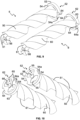
drive screw 4 is more clearly shown inFigure 7 , and comprises acenter shaft 40 and abody 41 molded on thecenter shaft 40. In this example, thebody 41 comprises two diametricallyopposite threads 42 along its length. - The
center shaft 40 comprises anchoring features 43 embedded in thebody 41 to anchor thecenter shaft 40 to thebody 41. In this example, the anchoring features 43 comprise two groups ofaxial splines 44 that extend along part of thecenter shaft 40. The two groups ofaxial splines 44 are spaced apart from one another along the length of thecenter shaft 40. - The
center shaft 40 also comprises amotor coupling 45 in the form of a diametrical slot designed to house therectangular protrusion 13 of theflexible coupling 11, although it can directly house the rectangular protrusion of the shaft of thedrive motor 10. In this example, thecenter shaft 40 is made of stainless steel and thebody 41 is made of a lubricated polymer material, specifically a glass fiber reinforced PPS material containing a solid or dry lubricant, such as polytetrafluorethylene (PTFE), molybdenum disulfide and carbon or graphite. - There are several advantages to using a
polymer screw body 41 molded on a stainless-steel center shaft 40. The presence of thecenter shaft 40 reduces the thickness of the material required to form thebody 41. The person skilled in the art will understand that this significantly reduces the cycle time and mitigates the tendency of the moldedbody 41 to deform when the material solidifies. In addition, the stiffness of thecenter shaft 40 also prevents thescrew 4 from bending or deforming under load when torque is applied to it by thedrive motor 10. - The person skilled in the art will also understand that this feature acts in synergy with the
flexible coupling 11 and the vibration-damping effect of the space E between theshell 33 and theinsert 34. -
Figures 9 and 10 show thedriven screws screw screws body 41 of thedrive screw 4 and/or different to that of theinsert 34. - Each driven
screw respective body opposite threads screw release coupling release coupling ring notches threads notches radial shoulders - The diameter of the
ring screw threads ring threads screw threads release coupling screw axial protrusion - In this example, the
threads screws screws screws release coupling screws - In this example, the
insert 34 comprises anannular step flow chamber 32 defined by each of theouter lobes annular steps rings screws flow chamber 32. - It will also be appreciated that the
screw threads release coupling screws - For example, the threads can each have a pitch and/or a diameter and/or a configuration that enables them to be ejected from a mold by applying an axial force to it, without applying a rotational force to it. More specifically, the threads can each have a helix angle that enables them to be ejected from a mold by applying an axial force to it, without applying a rotational force to it.
- By way of example only, the helix angle can be at least 60°, for example at least 70°, when the threads are made of a polymer, such as lubricated PPS.
- Referring now to
figures 11 through 15 , ascrew pump assembly 101 according to a second example is shown, which is similar to the first example in that similar features are marked with like numbers incremented by 100. Thescrew pump assembly 1 in this example differs from that of the first example in that it comprises three drivenscrews threads 142, which is more clearly illustrated inFigure 15 . - Therefore, the
tubular wall 135 has fourcylindrical lobes screws center lobe 135a approximates the outer surfaces of thecenter drive screw 104, with threeouter lobes center lobe 135a, each approximating the outer surfaces of a respective drivenscrew -
Figure 16 shows anotherscrew assembly Figure 11 instead of the screw assembly inFigure 15 . Thescrews screw assembly - A person skilled in the art will be aware that several variants of the aforementioned aspects are conceivable without departing from the scope of the disclosure.
- Throughout the description and claims of this specification, the words "comprise" and "contain" and their variations mean "including but not limited to" and are not intended for (and do not exclude) other parts, additives, components, integers or steps.
- Any features, integers, characteristics, compounds or groups described in connection with a particular aspect, embodiment or example of the disclosure are to be understood as being applicable to any other aspect, embodiment or example described herein, unless inconsistent therewith. All of the features disclosed in this specification (including the abstract and accompanying drawings), and/or all of the steps of a method or of a process thus disclosed, can be combined in any combination other than combinations wherein at least some of such features and/or steps are mutually exclusive. The disclosure is not limited to the details of all of the preceding aspects. The disclosure extends to any new feature or any new combination of features disclosed in this specification (including the abstract and accompanying drawings), or to any new feature, or any new combination, of the steps of any method or process thus disclosed.
-
- 1
- screw pump assembly
- 10
- motor
- 11
- flexible coupling
- 12
- first coupling feature
- 13
- second coupling feature
- 2
- screw pump
- 3
- casing
- 30
- inlet pipe
- 31
- outlet pipe
- 32
- flow chamber
- 32a
- annular step
- 32b
- annular step
- 33
- shell
- 33a
- closed end of shell
- 33b
- open end of shell
- 34
- insert
- 35
- tubular insert wall
- 35a
- cylindrical center lobe of the tubular wall
- 35b
- cylindrical outer lobe of the tubular wall
- 35c
- cylindrical outer lobe of the tubular wall
- 36
- anti-rotation tab s
- 37
- anti-rotation tabs
- 38
- circular flange
- 39a
- mounting disc
- 39b
- mounting disc
- 39c
- spacing interface
- 4
- drive screw
- 40
- drive screw center shaft
- 41
- drive screw body
- 43
- anchoring features
- 44
- axial splines
- 45
- motor coupling
- 5
- driven screw
- 50
- driven screw body
- 51
- driven screw threads
- 52
- release coupling
- 53
- release coupling ring
- 54
- release coupling notch
- 54a
- radial shoulder
- 55
- hole
- 56
- axial protrusion
- 6
- driven screw
- 60
- driven screw body
- 61
- driven screw threads
- 62
- release coupling
- 63
- release coupling ring
- 64
- release coupling notch
- 64a
- radial shoulder
- 65
- hole
- 66
- axial protrusion
- E
- space between insert and shell
- 101
- screw pump assembly
- 110
- motor
- 102
- screw pump
- 103
- casing
- 130
- inlet pipe
- 131
- outlet pipe
- 132
- flow chamber
- 133
- shell
- 133a
- closed end of shell
- 133b
- open end of shell
- 134
- insert
- 135
- tubular insert wall
- 135a
- cylindrical center lobe of the tubular wall
- 135b
- cylindrical outer lobe of the tubular wall
- 135c
- cylindrical outer lobe of the tubular wall
- 135d
- cylindrical outer lobe of the tubular wall
- 136
- anti-rotation tab s
- 137
- anti-rotation tabs
- 138
- circular flange
- 104
- drive screw
- 140
- drive screw center shaft
- 141
- drive screw body
- 145
- motor coupling
- 105
- driven screw
- 150
- driven screw body
- 151
- driven screw threads
- 156
- axial protrusion
- 106
- driven screw
- 160
- driven screw body
- 161
- driven screw threads
- 166
- axial protrusion
- 107
- driven screw
- 176
- axial protrusion
- 204
- drive screw
- 240
- drive screw center shaft
- 241
- drive screw body
- 245
- motor coupling
- 205
- driven screw
- 250
- driven screw body
- 251
- driven screw threads
- 256
- axial protrusion
- 206
- driven screw
- 260
- driven screw body
- 261
- driven screw threads
- 266
- axial protrusion
- 207
- driven screw
- 276
- axial protrusion
Claims (15)
- A screw pump (2) comprising:a casing (3) with an inlet (30), an outlet (31) and a flow chamber (32) between the inlet and the outlet; andat least two screws (4, 5, 6) housed in the flow chamber to force a fluid flow through the flow chamber from the inlet to the outlet;wherein at least one of the screws (5, 6) comprises a lubricated polymer material.
- The screw pump according to claim 1, wherein the lubricated polymer material comprises polyphenylene sulfide.
- The screw pump according to claim 1 or claim 2, wherein the lubricated polymer material comprises a fiber reinforced lubricated polymer material.
- The screw pump according to claim 3, wherein the lubricated polymer material comprises a glass fiber reinforced polyphenylene sulfide.
- The screw pump according to any one of the preceding claims, wherein the casing comprises a shell (33) within which an insert (34) defining the flow chamber is housed.
- The screw pump according to claim 5, wherein the flow chamber is defined by a tubular wall (35) of the insert that has a substantially constant wall thickness.
- The screw pump according to claim 5 or claim 6, wherein the insert comprises one or more anti-rotation protrusions (36, 37) which engage(s) with the shell to inhibit relative rotation between them.
- The screw pump according to any one of claims 5 to 7, wherein the insert (34) comprises a lubricated polymer material.
- The screw pump according to any one of claims 5 to 8, wherein the insert (34) comprises a lubricated polyphenylene sulfide material.
- The screw pump according to any one of claims 5 to 9, wherein the insert (34) comprises a fiber reinforced lubricated polymer material.
- The screw pump according to any one of claims 5 to 10, wherein the insert (34) comprises a glass fiber reinforced lubricated polyphenylene sulfide.
- The screw pump according to any one of the preceding claims, wherein at least one of the screws (4) comprises a center shaft (40) made of a first material on which the screw is molded from a second material that is less stiff than the first material.
- The screw pump according to claim 12, wherein the second material comprises lubricated polymer, such as a lubricated polyphenylene sulfide material.
- The screw pump according to claim 13, wherein the second material comprises a fiber reinforced lubricated polymer material, such as a glass fiber reinforced lubricated polyphenylene sulfide.
- The screw pump according to any one of the preceding claims, wherein at least one of the screws comprises threads with a helix angle of at least 60°.
Priority Applications (2)
| Application Number | Priority Date | Filing Date | Title |
|---|---|---|---|
| US18/734,744 US12560167B2 (en) | 2023-06-09 | 2024-06-05 | Screw pump and its components |
| CN202410728809.XA CN119103120A (en) | 2023-06-09 | 2024-06-06 | Screw pumps and their components |
Applications Claiming Priority (6)
| Application Number | Priority Date | Filing Date | Title |
|---|---|---|---|
| PCT/US2023/068206 WO2023240239A1 (en) | 2022-06-10 | 2023-06-09 | Screw pump and its components |
| PCT/US2023/068205 WO2023240238A1 (en) | 2022-06-10 | 2023-06-09 | Screw pump and its components |
| PCT/US2023/068197 WO2023240232A1 (en) | 2022-06-10 | 2023-06-09 | Screw pump and its components |
| PCT/US2023/068194 WO2023240231A1 (en) | 2022-06-10 | 2023-06-09 | Screw pump and its components |
| PCT/US2023/068200 WO2023240234A1 (en) | 2022-06-10 | 2023-06-09 | Screw pump and its components |
| EP23315447 | 2023-12-04 |
Publications (2)
| Publication Number | Publication Date |
|---|---|
| EP4474650A1 true EP4474650A1 (en) | 2024-12-11 |
| EP4474650B1 EP4474650B1 (en) | 2026-03-25 |
Family
ID=91070241
Family Applications (1)
| Application Number | Title | Priority Date | Filing Date |
|---|---|---|---|
| EP24176065.1A Active EP4474650B1 (en) | 2023-06-09 | 2024-05-15 | Screw pump and its components |
Country Status (3)
| Country | Link |
|---|---|
| US (1) | US12560167B2 (en) |
| EP (1) | EP4474650B1 (en) |
| CN (1) | CN119103120A (en) |
Families Citing this family (3)
| Publication number | Priority date | Publication date | Assignee | Title |
|---|---|---|---|---|
| KR20250021569A (en) * | 2022-06-10 | 2025-02-13 | 일리노이즈 툴 워크스 인코포레이티드 | Screw pumps and their components |
| US20250354549A1 (en) * | 2022-06-10 | 2025-11-20 | Illinois Tool Works Inc. | Screw pump and its components |
| US20250354551A1 (en) * | 2022-06-10 | 2025-11-20 | Illinois Tool Works Inc. | Screw pump and its components |
Citations (9)
| Publication number | Priority date | Publication date | Assignee | Title |
|---|---|---|---|---|
| JPH01301977A (en) * | 1988-05-31 | 1989-12-06 | Brother Ind Ltd | Screw rotor |
| JPH0275789A (en) * | 1988-09-08 | 1990-03-15 | Brother Ind Ltd | rotor |
| US5223052A (en) * | 1990-04-06 | 1993-06-29 | Hitachi, Ltd. | Method of treating surfaces of rotors of the screw type rotary machine |
| DE202009003980U1 (en) * | 2009-03-24 | 2010-08-19 | Vacuubrand Gmbh + Co Kg | vacuum pump |
| EP2423509A2 (en) * | 2010-08-26 | 2012-02-29 | Vacuubrand Gmbh + Co Kg | Vacuum pump |
| EP2532895A1 (en) * | 2011-06-06 | 2012-12-12 | Vacuubrand Gmbh + Co Kg | Vacuum pump with pump rotor bearings on a single side |
| US20130183185A1 (en) * | 2012-01-12 | 2013-07-18 | Vacuubrand Gmbh + Co Kg | Screw rotor for a screw type vacuum pump |
| US20200240411A1 (en) * | 2017-05-03 | 2020-07-30 | Kaeser Kompressoren Se | Screw Compressor with Multi-layered Coating of the Rotor Screws |
| CN211370726U (en) * | 2019-11-11 | 2020-08-28 | 海门市晶盛真空设备有限公司 | A pump casing of a screw vacuum pump |
Family Cites Families (78)
| Publication number | Priority date | Publication date | Assignee | Title |
|---|---|---|---|---|
| FR1245458A (en) | 1959-02-04 | 1960-11-04 | Imo Industri Ab | Helical gear pump |
| US3146723A (en) | 1959-04-13 | 1964-09-01 | Wildhaber Ernest | Screw pump unit |
| SE217570C1 (en) | 1966-09-27 | 1967-12-12 | ||
| DE2828348A1 (en) | 1978-06-28 | 1980-01-10 | Allweiler Ag | SCREW MACHINE |
| DE3019308C2 (en) | 1980-05-21 | 1982-09-02 | Christensen, Inc., 84115 Salt Lake City, Utah | Chisel direct drive for deep drilling tools |
| SE463829B (en) | 1985-03-15 | 1991-01-28 | Svenska Rotor Maskiner Ab | AATMINSTONE SCREWING MACHINE A ROTOR CONTAINING PLASTIC MATERIAL |
| US5165881A (en) | 1991-09-16 | 1992-11-24 | Opcon Autorotor Ab | Rotor for a screw rotor machine |
| US5865239A (en) | 1997-02-05 | 1999-02-02 | Micropump, Inc. | Method for making herringbone gears |
| DE10051731A1 (en) | 2000-10-18 | 2002-05-02 | Mannesmann Rexroth Ag | Screw pump esp. for low pressure operation consists partially of plastic with glass/carbon fiber reinforcement |
| GB2401399A (en) | 2003-05-08 | 2004-11-10 | Automotive Motion Tech Ltd | Casing wall recesses reduce shear loss in screw pumps |
| US7232297B2 (en) | 2003-05-08 | 2007-06-19 | Automotive Motion Technology Limited | Screw pump |
| JPWO2005124154A1 (en) * | 2004-06-15 | 2008-04-10 | 株式会社豊田自動織機 | Screw pump and screw gear |
| BE1016762A3 (en) | 2005-09-13 | 2007-06-05 | Atlas Copco Airpower Nv | IMPROVED SCREW OF A WATER INJECTED SCREW COMPRESSOR AND A MANUFACTURING METHOD. |
| GB0525378D0 (en) | 2005-12-13 | 2006-01-18 | Boc Group Plc | Screw Pump |
| DE102006035782B4 (en) * | 2006-08-01 | 2018-10-25 | Gea Refrigeration Germany Gmbh | Screw compressor for extremely high operating pressures |
| CN101153599B (en) | 2006-09-28 | 2010-07-28 | 株式会社神户制钢所 | Screw rotor |
| US8314474B2 (en) | 2008-07-25 | 2012-11-20 | Ati Technologies Ulc | Under bump metallization for on-die capacitor |
| US8096797B2 (en) * | 2008-10-28 | 2012-01-17 | 592301 Alberta Ltd. | Roots type gear compressor with helical lobes having feedback cavity |
| DE102008064159B3 (en) | 2008-12-19 | 2010-01-28 | Bühler Motor GmbH | Electronically commutated direct current motor for liquid pump, has insulating body integrally provided with receivers, and conductor plate fastened to insulating body in axially and radially form-fit manner |
| DE102009049311B4 (en) | 2009-10-14 | 2012-11-29 | Brinkmann Pumpen K.H. Brinkmann Gmbh & Co. Kg | Screw machine and method for its production |
| DE202009014604U1 (en) | 2009-10-29 | 2010-01-28 | Jung & Co. Gerätebau GmbH | Screw pump with coupling |
| DE102011079226B4 (en) | 2011-07-15 | 2014-12-24 | Bühler Motor GmbH | Liquid pump, in particular water pump |
| WO2014081823A1 (en) | 2012-11-20 | 2014-05-30 | Eaton Corporation | Composite supercharger rotors and methods of construction thereof |
| DE102014102390B3 (en) | 2014-02-25 | 2015-03-26 | Leistritz Pumpen Gmbh | Screw Pump |
| DE102014220201A1 (en) | 2014-10-06 | 2016-04-07 | Bühler Motor GmbH | Electronically commutated DC motor, in particular for an oil pump |
| DE102015210908A1 (en) | 2015-06-15 | 2016-12-15 | Bühler Motor GmbH | Electric motor driven liquid pump |
| DE102015218679B4 (en) | 2015-09-29 | 2019-08-29 | Skf Lubrication Systems Germany Gmbh | Screw Pump |
| DE102016202260A1 (en) | 2016-02-15 | 2017-08-17 | Bühler Motor GmbH | Pump drive for the promotion of a reducing agent for vehicle exhaust systems, modular motor and pump family to form different pump drives with several such electric motors |
| DE102016206404A1 (en) | 2016-04-15 | 2017-10-19 | Bühler Motor GmbH | Electric motor, in particular pump motor |
| DE102016206405A1 (en) | 2016-04-15 | 2017-10-19 | Bühler Motor GmbH | Pump motor with a fixed bearing |
| DE102016206406A1 (en) | 2016-04-15 | 2017-10-19 | Bühler Motor GmbH | Pump motor with a containment shell |
| EP3239532A1 (en) | 2016-04-26 | 2017-11-01 | TI Automotive Technology Center GmbH | Fuel pump with reduced height in the axial direction |
| DE102017205847A1 (en) | 2017-04-06 | 2018-10-11 | Bühler Motor GmbH | Electronically commutated DC motor and method for assembling an electronically commutated DC motor |
| DE102017112743B3 (en) | 2017-06-09 | 2018-10-25 | Leistritz Pumpen Gmbh | Modular system for producing a screw pump |
| DE102017121882B3 (en) | 2017-09-21 | 2019-01-24 | Leistritz Pumpen Gmbh | Screw Pump |
| DE102017218287B4 (en) | 2017-10-12 | 2021-12-23 | Vitesco Technologies GmbH | Fuel pump and fuel delivery unit |
| JP6895585B2 (en) | 2018-03-30 | 2021-06-30 | 株式会社日立産機システム | Screw rotor, fluid machine body and fluid machine |
| DE102018112492B3 (en) | 2018-05-24 | 2019-10-10 | Itt Bornemann Gmbh | Screw Pump |
| DE102018130472A1 (en) | 2018-11-30 | 2020-06-04 | Nidec Gpm Gmbh | Screw pump |
| DE102018222516A1 (en) | 2018-12-20 | 2020-06-25 | Audi Ag | Drive device for a motor vehicle |
| DE102019103470A1 (en) | 2019-02-12 | 2020-08-13 | Nidec Gpm Gmbh | Electric screw spindle coolant pump |
| US11867180B2 (en) * | 2019-03-22 | 2024-01-09 | Copeland Industrial Lp | Seal assembly for high pressure single screw compressor |
| DE102019209115A1 (en) | 2019-06-24 | 2020-12-24 | Audi Ag | Coolant circuit for a drive device and a method for operating a coolant circuit |
| DE102019118094A1 (en) | 2019-07-04 | 2021-01-07 | Nidec Gpm Gmbh | Temperature control device for a battery storage module |
| DE102019118086A1 (en) | 2019-07-04 | 2021-01-07 | Nidec Gpm Gmbh | Integrated screw spindle coolant pump |
| DE102019210873A1 (en) | 2019-07-23 | 2021-01-28 | Audi Ag | Screw pump for conveying a fluid and a corresponding screw pump arrangement |
| DE102019128602B3 (en) | 2019-10-23 | 2021-02-11 | Leistritz Pumpen Gmbh | Screw pump |
| EP3816419B1 (en) | 2019-10-31 | 2025-07-16 | Illinois Tool Works Inc. | Screw pump and a cooling circuit of a vehicle presenting such a pump |
| EP3816446B1 (en) | 2019-10-31 | 2025-07-02 | Illinois Tool Works Inc. | Cooling circuit of a vehicule |
| DE102020113372A1 (en) | 2020-05-18 | 2021-11-18 | Leistritz Pumpen Gmbh | Screw pump |
| DE102020122460A1 (en) | 2020-08-27 | 2022-03-03 | Leistritz Pumpen Gmbh | Process and screw pump for conveying a gas-liquid mixture |
| EP4008903B1 (en) | 2020-12-04 | 2023-01-25 | ViscoTec Pumpen- und Dosiertechnik GmbH | Rotor unit and eccentric screw pump |
| CN112539171B (en) | 2020-12-07 | 2022-11-11 | 浙江博大泵业有限公司 | Two-head three-head glue-applying double screw |
| DE102020133555A1 (en) | 2020-12-15 | 2022-06-15 | Leistritz Pumpen Gmbh | screw pump |
| US11913370B2 (en) | 2021-02-10 | 2024-02-27 | Illinois Tool Works Inc. | Valve assembly failsafe |
| IT202100004139A1 (en) | 2021-02-23 | 2022-08-23 | Settima Mecc S R L | ASSEMBLY OF SCREWS FOR THREE-SCREW PUMP AND SCREW PUMP COMPRISING THIS ASSEMBLY |
| IT202100004148A1 (en) | 2021-02-23 | 2022-08-23 | Settima Mecc S R L | ASSEMBLY OF SCREWS FOR THREE-SCREW PUMP AND THREE-SCREW PUMP INCLUDING THIS ASSEMBLY |
| FR3120570B1 (en) | 2021-03-11 | 2024-06-14 | Psa Automobiles Sa | ASSEMBLY COMPRISING MOTOR VEHICLE FLUID REGULATION UNITS |
| GB2608630A (en) | 2021-07-08 | 2023-01-11 | Leybold Gmbh | Screw pump, screw rotor, method of manufacturing a screw rotor, and use of a screw pump or a screw rotor |
| IT202100019787A1 (en) * | 2021-07-26 | 2023-01-26 | Fluid O Tech Srl | IMPROVED SCREW PUMP, ESPECIALLY FOR COOLING SYSTEMS. |
| DE102021131017B4 (en) | 2021-11-25 | 2025-02-06 | Bühler Motor GmbH | liquid pump with optimized cooling and heat dissipation |
| DE102021133099A1 (en) | 2021-12-14 | 2023-06-15 | Leistritz Pumpen Gmbh | screw pump |
| DE102021133114A1 (en) | 2021-12-14 | 2023-06-15 | Leistritz Pumpen Gmbh | screw pump |
| DE102021133109A1 (en) | 2021-12-14 | 2023-06-15 | Leistritz Pumpen Gmbh | screw pump |
| DE102021133112A1 (en) | 2021-12-14 | 2023-06-15 | Leistritz Pumpen Gmbh | screw pump |
| DE102021133106A1 (en) | 2021-12-14 | 2023-06-15 | Leistritz Pumpen Gmbh | screw pump |
| DE102021133495B4 (en) | 2021-12-16 | 2025-07-24 | Bühler Motor GmbH | Electronically commutated fluid pump with efficient heat dissipation from the electronic components and the stator winding |
| DE202021106860U1 (en) | 2021-12-16 | 2022-12-20 | Bühler Motor GmbH | Electronically commutated fluid pump |
| DE102021133484A1 (en) | 2021-12-16 | 2023-06-22 | Bühler Motor GmbH | Electronically commutated fluid pump |
| DE202021106861U1 (en) | 2021-12-16 | 2022-12-20 | Bühler Motor GmbH | Electronically commutated fluid pump |
| FR3136522A1 (en) | 2022-06-10 | 2023-12-15 | Illinois Tool Works | SCREW PUMP AND ITS COMPONENTS |
| FR3136525A1 (en) | 2022-06-10 | 2023-12-15 | Illinois Tool Works | SCREW PUMP AND ITS COMPONENTS |
| FR3136521A1 (en) | 2022-06-10 | 2023-12-15 | Illinois Tool Works | SCREW PUMP AND ITS COMPONENTS |
| FR3136524A1 (en) | 2022-06-10 | 2023-12-15 | Illinois Tool Works | SCREW PUMP AND ITS COMPONENTS |
| FR3136523A1 (en) | 2022-06-10 | 2023-12-15 | Illinois Tool Works | SCREW PUMP AND ITS COMPONENTS |
| KR102658957B1 (en) | 2022-11-03 | 2024-04-22 | 주식회사 코아비스 | Screw pump |
| DE102022131340B4 (en) | 2022-11-28 | 2025-05-08 | Bühler Motor GmbH | Contact body for at least one liquid pump in motor vehicles |
| DE102023105784B4 (en) | 2023-03-08 | 2024-10-31 | Bühler Motor GmbH | pump valve arrangement |
-
2024
- 2024-05-15 EP EP24176065.1A patent/EP4474650B1/en active Active
- 2024-06-05 US US18/734,744 patent/US12560167B2/en active Active
- 2024-06-06 CN CN202410728809.XA patent/CN119103120A/en active Pending
Patent Citations (9)
| Publication number | Priority date | Publication date | Assignee | Title |
|---|---|---|---|---|
| JPH01301977A (en) * | 1988-05-31 | 1989-12-06 | Brother Ind Ltd | Screw rotor |
| JPH0275789A (en) * | 1988-09-08 | 1990-03-15 | Brother Ind Ltd | rotor |
| US5223052A (en) * | 1990-04-06 | 1993-06-29 | Hitachi, Ltd. | Method of treating surfaces of rotors of the screw type rotary machine |
| DE202009003980U1 (en) * | 2009-03-24 | 2010-08-19 | Vacuubrand Gmbh + Co Kg | vacuum pump |
| EP2423509A2 (en) * | 2010-08-26 | 2012-02-29 | Vacuubrand Gmbh + Co Kg | Vacuum pump |
| EP2532895A1 (en) * | 2011-06-06 | 2012-12-12 | Vacuubrand Gmbh + Co Kg | Vacuum pump with pump rotor bearings on a single side |
| US20130183185A1 (en) * | 2012-01-12 | 2013-07-18 | Vacuubrand Gmbh + Co Kg | Screw rotor for a screw type vacuum pump |
| US20200240411A1 (en) * | 2017-05-03 | 2020-07-30 | Kaeser Kompressoren Se | Screw Compressor with Multi-layered Coating of the Rotor Screws |
| CN211370726U (en) * | 2019-11-11 | 2020-08-28 | 海门市晶盛真空设备有限公司 | A pump casing of a screw vacuum pump |
Also Published As
| Publication number | Publication date |
|---|---|
| EP4474650B1 (en) | 2026-03-25 |
| US20240410363A1 (en) | 2024-12-12 |
| CN119103120A (en) | 2024-12-10 |
| US12560167B2 (en) | 2026-02-24 |
Similar Documents
| Publication | Publication Date | Title |
|---|---|---|
| EP4474650B1 (en) | Screw pump and its components | |
| WO2023240231A1 (en) | Screw pump and its components | |
| WO2023240238A1 (en) | Screw pump and its components | |
| WO2023240239A1 (en) | Screw pump and its components | |
| WO2023240232A1 (en) | Screw pump and its components | |
| WO2023240234A1 (en) | Screw pump and its components | |
| CA2636730C (en) | Positive displacement motor/progressive cavity pump | |
| BRPI0606764B1 (en) | decoupler assembly to transfer torque between a shaft and a drive belt | |
| CA1177477A (en) | Direct drive bit for deep well drilling tools | |
| CA2113878C (en) | Shaft seal and bore assembly | |
| US20250314248A1 (en) | Screw pump and its components | |
| US20250354551A1 (en) | Screw pump and its components | |
| US20250361863A1 (en) | Screw pump and its components | |
| EP3299653A1 (en) | Decoupler assembly | |
| CN119096058A (en) | Pump device for a pump, method for producing such a pump device, pump having such a pump device and method for installing such a pump | |
| US20260132787A1 (en) | Screw Pump and its Components | |
| US20250354549A1 (en) | Screw pump and its components | |
| EP4536975A1 (en) | Screw pump and its components | |
| EP2212558A2 (en) | Fixation arrangement for an oil pump in a refrigeration compressor | |
| US7306375B2 (en) | Bearing locking collar retainer | |
| US4942856A (en) | Ignition distributor for an internal combustion engine | |
| HU202631B (en) | Eccentric scroll pump | |
| JPH02153278A (en) | Oil feeding device for compressor |
Legal Events
| Date | Code | Title | Description |
|---|---|---|---|
| PUAI | Public reference made under article 153(3) epc to a published international application that has entered the european phase |
Free format text: ORIGINAL CODE: 0009012 |
|
| STAA | Information on the status of an ep patent application or granted ep patent |
Free format text: STATUS: THE APPLICATION HAS BEEN PUBLISHED |
|
| AK | Designated contracting states |
Kind code of ref document: A1 Designated state(s): AL AT BE BG CH CY CZ DE DK EE ES FI FR GB GR HR HU IE IS IT LI LT LU LV MC ME MK MT NL NO PL PT RO RS SE SI SK SM TR |
|
| STAA | Information on the status of an ep patent application or granted ep patent |
Free format text: STATUS: REQUEST FOR EXAMINATION WAS MADE |
|
| 17P | Request for examination filed |
Effective date: 20250611 |
|
| GRAP | Despatch of communication of intention to grant a patent |
Free format text: ORIGINAL CODE: EPIDOSNIGR1 |
|
| STAA | Information on the status of an ep patent application or granted ep patent |
Free format text: STATUS: GRANT OF PATENT IS INTENDED |
|
| INTG | Intention to grant announced |
Effective date: 20251113 |
|
| GRAS | Grant fee paid |
Free format text: ORIGINAL CODE: EPIDOSNIGR3 |
|
| GRAA | (expected) grant |
Free format text: ORIGINAL CODE: 0009210 |
|
| STAA | Information on the status of an ep patent application or granted ep patent |
Free format text: STATUS: THE PATENT HAS BEEN GRANTED |
|
| P01 | Opt-out of the competence of the unified patent court (upc) registered |
Free format text: CASE NUMBER: UPC_APP_0004024_4474650/2026 Effective date: 20260203 |
|
| AK | Designated contracting states |
Kind code of ref document: B1 Designated state(s): AL AT BE BG CH CY CZ DE DK EE ES FI FR GB GR HR HU IE IS IT LI LT LU LV MC ME MK MT NL NO PL PT RO RS SE SI SK SM TR |
|
| REG | Reference to a national code |
Ref country code: CH Ref legal event code: F10 Free format text: ST27 STATUS EVENT CODE: U-0-0-F10-F00 (AS PROVIDED BY THE NATIONAL OFFICE) Effective date: 20260325 Ref country code: GB Ref legal event code: FG4D |
|
| REG | Reference to a national code |
Ref country code: DE Ref legal event code: R096 Ref document number: 602024003358 Country of ref document: DE |
|
| REG | Reference to a national code |
Ref country code: IE Ref legal event code: FG4D |