EP4474625A1 - Steam discharge pipe blowback protection system - Google Patents
Steam discharge pipe blowback protection system Download PDFInfo
- Publication number
- EP4474625A1 EP4474625A1 EP24173613.1A EP24173613A EP4474625A1 EP 4474625 A1 EP4474625 A1 EP 4474625A1 EP 24173613 A EP24173613 A EP 24173613A EP 4474625 A1 EP4474625 A1 EP 4474625A1
- Authority
- EP
- European Patent Office
- Prior art keywords
- steam
- discharge pipe
- steam discharge
- drip pan
- blowback
- Prior art date
- Legal status (The legal status is an assumption and is not a legal conclusion. Google has not performed a legal analysis and makes no representation as to the accuracy of the status listed.)
- Pending
Links
Images



Classifications
-
- F—MECHANICAL ENGINEERING; LIGHTING; HEATING; WEAPONS; BLASTING
- F22—STEAM GENERATION
- F22B—METHODS OF STEAM GENERATION; STEAM BOILERS
- F22B37/00—Component parts or details of steam boilers
- F22B37/02—Component parts or details of steam boilers applicable to more than one kind or type of steam boiler
- F22B37/06—Flue or fire tubes; Accessories therefor, e.g. fire-tube inserts
-
- F—MECHANICAL ENGINEERING; LIGHTING; HEATING; WEAPONS; BLASTING
- F01—MACHINES OR ENGINES IN GENERAL; ENGINE PLANTS IN GENERAL; STEAM ENGINES
- F01K—STEAM ENGINE PLANTS; STEAM ACCUMULATORS; ENGINE PLANTS NOT OTHERWISE PROVIDED FOR; ENGINES USING SPECIAL WORKING FLUIDS OR CYCLES
- F01K13/00—General layout or general methods of operation of complete plants
- F01K13/02—Controlling, e.g. stopping or starting
-
- F—MECHANICAL ENGINEERING; LIGHTING; HEATING; WEAPONS; BLASTING
- F01—MACHINES OR ENGINES IN GENERAL; ENGINE PLANTS IN GENERAL; STEAM ENGINES
- F01K—STEAM ENGINE PLANTS; STEAM ACCUMULATORS; ENGINE PLANTS NOT OTHERWISE PROVIDED FOR; ENGINES USING SPECIAL WORKING FLUIDS OR CYCLES
- F01K23/00—Plants characterised by more than one engine delivering power external to the plant, the engines being driven by different fluids
- F01K23/02—Plants characterised by more than one engine delivering power external to the plant, the engines being driven by different fluids the engine cycles being thermally coupled
- F01K23/06—Plants characterised by more than one engine delivering power external to the plant, the engines being driven by different fluids the engine cycles being thermally coupled combustion heat from one cycle heating the fluid in another cycle
- F01K23/10—Plants characterised by more than one engine delivering power external to the plant, the engines being driven by different fluids the engine cycles being thermally coupled combustion heat from one cycle heating the fluid in another cycle with exhaust fluid of one cycle heating the fluid in another cycle
- F01K23/101—Regulating means specially adapted therefor
-
- F—MECHANICAL ENGINEERING; LIGHTING; HEATING; WEAPONS; BLASTING
- F22—STEAM GENERATION
- F22B—METHODS OF STEAM GENERATION; STEAM BOILERS
- F22B1/00—Methods of steam generation characterised by form of heating method
- F22B1/02—Methods of steam generation characterised by form of heating method by exploitation of the heat content of hot heat carriers
- F22B1/18—Methods of steam generation characterised by form of heating method by exploitation of the heat content of hot heat carriers the heat carrier being a hot gas, e.g. waste gas such as exhaust gas of internal-combustion engines
- F22B1/1807—Methods of steam generation characterised by form of heating method by exploitation of the heat content of hot heat carriers the heat carrier being a hot gas, e.g. waste gas such as exhaust gas of internal-combustion engines using the exhaust gases of combustion engines
- F22B1/1815—Methods of steam generation characterised by form of heating method by exploitation of the heat content of hot heat carriers the heat carrier being a hot gas, e.g. waste gas such as exhaust gas of internal-combustion engines using the exhaust gases of combustion engines using the exhaust gases of gas-turbines
-
- F—MECHANICAL ENGINEERING; LIGHTING; HEATING; WEAPONS; BLASTING
- F22—STEAM GENERATION
- F22B—METHODS OF STEAM GENERATION; STEAM BOILERS
- F22B37/00—Component parts or details of steam boilers
- F22B37/02—Component parts or details of steam boilers applicable to more than one kind or type of steam boiler
- F22B37/22—Drums; Headers; Accessories therefor
- F22B37/226—Protection of drums against combustion
-
- F—MECHANICAL ENGINEERING; LIGHTING; HEATING; WEAPONS; BLASTING
- F22—STEAM GENERATION
- F22B—METHODS OF STEAM GENERATION; STEAM BOILERS
- F22B37/00—Component parts or details of steam boilers
- F22B37/02—Component parts or details of steam boilers applicable to more than one kind or type of steam boiler
- F22B37/42—Applications, arrangements or dispositions of alarm or automatic safety devices
- F22B37/44—Applications, arrangements or dispositions of alarm or automatic safety devices of safety valves
Definitions
- the present application and the resultant patent relate generally to combined cycle power systems and more particularly relate to a steam discharge pipe blowback protection system to accommodate steam blowback as well as eccentricity in the discharge piping due to thermal growth at startup until equilibrium is reached.
- Power systems typically include a number of different turbomachines that are used to generate power output.
- Conventional combined cycle power plants use one or more gas turbine systems operatively coupled to one or more steam turbine systems.
- the gas turbine system includes a compressor coupled to an expansion (gas) turbine.
- the expansion turbine is usually coupled to and drives an external component, such as a generator, for producing a load or power output.
- the steam turbine system generally includes a high pressure (HP) turbine portion operatively coupled to an intermediate pressure (IP) turbine portion that, in turn, is coupled to a low pressure (LP) turbine. Similar to the expansion turbine of the gas turbine system, the various steam turbine portions are used to drive an external component such as a generator.
- HP high pressure
- IP intermediate pressure
- LP low pressure
- exhaust gas from the expansion turbine is passed to a heat recovery steam generator (HRSG), which may be used to reheat and provide steam to the various turbines portions of the steam turbine system for enhanced efficiency.
- HRSG heat recovery steam generator
- Exhaust gas from the heat recovery steam generator may be released to the atmosphere through a stack.
- certain components may experience high stress and thermal fatigue due to a rapid temperature change.
- the heat recovery steam generator may immediately begin to generate high temperature steam.
- This high temperature steam may be provided to the various components such as a boiler of the heat recovery steam generator and then to outlet components such as the steam headers and the steam outlet manifold, which vents steam to atmosphere.
- outlet components such as the steam headers and the steam outlet manifold, which vents steam to atmosphere.
- the system reaches an equilibrium condition, there is the potential of misalignment of the connected outlet components, because some components are exposed to high temperature steam while other components are at ambient temperature.
- Steam blowback is a phenomenon that may occur when steam is initially ejected into a downstream pipe and creates a plume of steam behind the steam inlet.
- Existing designs for the drip pan of a steam discharge pipe were insufficient to prevent such steam blowback from the steam manifold. Such escaping steam may be a danger to those nearby.
- the present application and the resultant patent thus provide a steam discharge pipe blowback protection system for use with a steam discharge pipe and a flow of steam therethrough.
- the steam discharge pipe blowback protection system may include a vent stack pipe and a drip pan with an exit end of the steam discharge pipe extending through the drip pan and into the vent stack pipe.
- the drip pan includes a slide plate positioned around the steam discharge pipe such that a blowback in the flow of steam causes the slide plate to seal the drip pan.
- the present application and the resultant patent further provide a method of flowing steam from a steam discharge pipe through a drip pan and into a vent stack pipe.
- the method may include the steps of initiating a flow of steam through the steam discharge pipe, receiving a blowback of steam from the steam discharge pipe into the drip pan such that the blowback of steam creates a positive pressure inside the drip pan and forces a slide plate to seal the drip pan, flowing an additional flow of steam into the vent stack pipe to achieve a steady state such that the additional flow of steam creates a negative pressure inside the drip pan and forces the slide plate to open the drip pan, and flowing ambient air into the flow of steam in the vent stack pipe.
- the present application and the resultant patent further provide a heat recovery steam generator with a flow of steam therethrough.
- the heat recovery steam generator may include a steam discharge pipe to vent the flow of steam, a vent stack pipe to receive the flow of steam from the steam discharge pipe, and a drip pan surrounding the steam discharge pipe and the vent stack pipe.
- the drip pan includes a slide plate positioned around the steam discharge pipe such that a blowback in the flow of steam causes the slide plate to seal the drip pan.
- FIG. 1 is a schematic diagram of an exemplary embodiment of a combined cycle power generation system 10.
- the combined cycle power generation system 10 may include a gas turbine system, a steam turbine system, and a heat recovery steam generator (HRSG).
- the combined cycle system 10 may include a gas turbine system 12 for driving a first generator 14 to produce electrical power.
- the gas turbine system 12 may include a turbine 16 (e.g., an expansion turbine), a combustor 18, and a compressor 20.
- the combined cycle system 10 also may include a steam turbine system 22 for driving a second generator 24.
- the steam turbine system 22 may include a low-pressure section 26 (LP ST), an intermediate-pressure section 28 (IP ST), and a high-pressure section 30 (HP ST).
- LP ST low-pressure section 26
- IP ST intermediate-pressure section 28
- HP ST high-pressure section 30
- the gas turbine system 12 and the steam turbine system 22 may drive separate generators 14 and 24 as is shown herein, the gas turbine system 12 and the steam turbine system 22 also may be utilized in tandem to drive a single load via a single shaft.
- the generators and components described herein and the like may be incorporated into other types of power generation systems.
- the combined cycle system 10 also may include a multi-stage heat recovery steam generator 32. Heated exhaust gas from the gas turbine system 12 may be directed into the heat recovery steam generator 32 to heat the steam used to power the steam turbine system 22.
- the heat recovery steam generator 32 may be fluidly connected and/or coupled with the turbine 16 via an exhaust channel 34 to provide exhaust fluid gases to the heat recovery steam generator 32 to be utilized in generating and/or heating steam therein.
- the heat recovery steam generator 32 may be fluidly connected and/or coupled with the sections of the steam turbine system 22 via one or more exhaust conduit(s) 40 to receive steam as well as one or more supply conduits 42 to provide steam to sections of the steam turbine system 22.
- Exhaust from the low-pressure section 26 of the steam turbine 22 may be directed into a condenser 36. Condensate from the condenser 36 may, in turn, be directed into a low-pressure section of the heat recovery steam generator 32 with the aid of a condensate pump 38. One or more exhaust stacks 44 of the heat recovery steam generator 32 may exhaust or release gas and/or fluid from heat recovery steam generator 32 into the atmosphere. Other components and other configurations may be used herein.
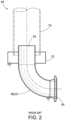
- FIG. 2 shows an example of a portion of a known exhaust stack 44.
- the exhaust stack 44 may include a safety valve 46 attached to a steam discharge pipe 48.
- the steam discharge pipe 48 may have an elbow configuration 50.
- One end of the steam discharge pipe 48 may be attached to the safety valve 46 and the other end may extend into a drip pan 52 and a vent stack pipe 54.
- an exit end 56 of the steam discharge pipe 48 may extend through the drip pan 52 and into the vent stack pipe 54.
- the diameter of the steam discharge pipe 48 is smaller than the diameter of the vent stack pipe 54, which has a diameter that is smaller than the diameter of the drip pan 52.
- steam may be vented into the exhaust stack 44 during, for example, start-up procedures.
- the high temperature of the steam may cause a thermal mismatch between the high temperature components and the ambient temperature components until an equilibrium is reached.
- a blowback of steam may allow the steam to escape between the drip pan 52 and the vent stack pipe 54 when exiting the steam discharge pipe 48 instead of being vented directly into the vent stack pipe 54.
- the steam may flow through the steam discharge pipe 48 into the vent stack pipe 54, where the steam reverses flow into the drip pan 52. Because the drip pan 52 is open at the top, this blowback of steam may create a hazardous situation for those nearby.
- FIGS. 3 and 4 show a steam discharge pipe blowback protection system 100 as may be described herein.
- the steam discharge pipe blowback protection system 100 may be used with the steam discharge pipe 48 as described above or any source of a heated fluid.
- the steam discharge pipe blowback protection system 100 may include a vent stack pipe 110.
- the exit end 56 of the steam discharge pipe 48 extends into the vent stack pipe 110.
- the diameter of the steam discharge pipe 48 is smaller than the diameter of the vent stack pipe 110, and the diameter of the vent stack pipe 110 is smaller than the diameter of a drip pan 160, as discussed below.
- the vent stack pipe 110 may include a number of apertures 120 at a lower end 130 thereof.
- the apertures 120 may be defined between a number of fillets 140.
- the apertures 120 may be largely rectangular 150 in shape and uniformly shaped, although any shape, any number, and any spacing may be used.
- the apertures 120 may be formed in the lower end 130 of the vent stack pipe 110, or the lower end 130 may be a separate element that is joined to the vent stack pipe 110.
- the apertures 120 on the lower end 130 of the vent stack pipe 110 are positioned inward of, or below, a top end wall 180 of the drip pan 160, such that the apertures 120 are in fluid communication with the interior of the drip pan 160. As shown in FIG. 3 , the end of the steam discharge pipe 48 extends beyond (above) the apertures 120.
- the drip pan 160 may be positioned between the steam discharge pipe 48 and the vent stack pipe 110.
- the drip pan 160 may have a bottom or first end wall 170 positioned about and radially outward from, the steam discharge pipe 48, a top or second end wall 180 positioned about and joined to the vent stack pipe 110, and a sidewall 190 extending between the two end walls 170, 180.
- the respective walls 170, 180, 190 may be connected via a number of welds 200 or other types of permanent connection means.
- the bottom or the first end wall 170 may have a support ledge 210 extending vertically therein (and parallel to the sidewall 190), which surrounds and is spaced apart from the steam discharge pipe 48.
- a slide plate 220 may be positioned on the support ledge 210.
- the slide plate 220 may have a central aperture 230 sized for the diameter of the steam discharge pipe 48.
- the slide plate 220 has a diameter less than the diameter of the drip pan 160 but greater than the diameter of the vent stack pipe 110, such that the slide plate 220 is not capable of being sucked into the vent stack pipe 110 during operation.
- the slide plate 220 may be maneuverable up and down the steam discharge pipe 48 within confines of the walls 170, 180, 190 of the drip pan 160.
- the slide plate 220 and the lower end 130 of the vent stack pipe 54 may be separated by a predetermined clearance distance 240.
- the bottom or the first wall 170 of the drip pan 160 may include a drain 250 formed therein.
- the top or the second end wall 180 may be welded or otherwise fixedly attached to the vent stack pipe 110. Other components and other configurations may be used herein.
- FIGS. 5 and 6 show the steam discharge pipe blowback protection system 100 in operation.
- the flow of steam may extend into the lower end 130 of the vent stack pipe 110 and may circulate turbulently through the apertures 120 therein and into plenum defined by the drip pan 160.
- This turbulent flow causes a positive ( i.e., greater than atmospheric) in pressure that will force the slide plate 220 downward against the support ledge 210 on the first wall 170 as is shown in FIGS. 3 and 5 . This position effectively seals the drip pan 160 and prevents the flow of steam from escaping therefrom.
- a normal or laminar flow of steam may extend through the vent stack pipe 110.
- this normal flow will decrease the pressure within the drip pan 160 below atmospheric pressure (i.e., to a negative pressure).
- the reduction in pressure will allow the slide plate 220 to be drawn off the support ledge 210 along the steam discharge pipe 48 as is shown in FIG. 6 .
- a flow of ambient air then may be forced into the drip pan 160 and may be entrained into the flow of steam. Specifically, air flows between the steam discharge pipe 48 and the support ledge 210 into the gap between the raised slide plate 220 and the top of the support ledge 210 and into the plenum defined by the wall 170, 180, 190 of the drip pan 160.
- Air can enter the vent stack pipe 110 via the apertures 120 in the lower end 130 thereof and become entrained with the steam flow.
- the entrained air flow provides a layer of film along the interior of the vent stack pipe 110 and ensures that shock waves within the flow of steam are buffered from the wall of the vent stack pipe 110.
- the steam discharge pipe blowback protection system 100 thus helps alleviate the complex connections of the components in the exhaust stack 44 by allowing for position mismatch. Likewise, the steam discharge pipe blowback protection system 100 protects against steam blowback escaping therefrom. Further, after this moment of blowback, the steam discharge pipe blowback protection system 100 then allow air to be entrained into the flow of steam for overall stable operation.
Landscapes
- Engineering & Computer Science (AREA)
- Chemical & Material Sciences (AREA)
- Combustion & Propulsion (AREA)
- General Engineering & Computer Science (AREA)
- Mechanical Engineering (AREA)
- Physics & Mathematics (AREA)
- Thermal Sciences (AREA)
- Sustainable Energy (AREA)
- Sustainable Development (AREA)
- Life Sciences & Earth Sciences (AREA)
- Pipeline Systems (AREA)
- Engine Equipment That Uses Special Cycles (AREA)
- Cookers (AREA)
Abstract
The present application provides a steam discharge pipe blowback protection system (100) for use with a steam discharge pipe (48) and a flow of steam therethrough. The steam discharge pipe blowback protection system (100) may include a vent stack pipe (110) and a drip pan (160) with an exit end (56) of the steam discharge pipe (48) extending through the drip pan (160) and into the vent stack pipe (110). The drip pan (160) includes a slide plate (220) positioned around the steam discharge pipe (48) such that a blowback in the flow of steam causes the slide plate (220) to seal the drip pan (160).
Description
- The present application and the resultant patent relate generally to combined cycle power systems and more particularly relate to a steam discharge pipe blowback protection system to accommodate steam blowback as well as eccentricity in the discharge piping due to thermal growth at startup until equilibrium is reached.
- Power systems typically include a number of different turbomachines that are used to generate power output. Conventional combined cycle power plants use one or more gas turbine systems operatively coupled to one or more steam turbine systems. The gas turbine system includes a compressor coupled to an expansion (gas) turbine. The expansion turbine is usually coupled to and drives an external component, such as a generator, for producing a load or power output. The steam turbine system generally includes a high pressure (HP) turbine portion operatively coupled to an intermediate pressure (IP) turbine portion that, in turn, is coupled to a low pressure (LP) turbine. Similar to the expansion turbine of the gas turbine system, the various steam turbine portions are used to drive an external component such as a generator. In a typical combined cycle power plant, exhaust gas from the expansion turbine is passed to a heat recovery steam generator (HRSG), which may be used to reheat and provide steam to the various turbines portions of the steam turbine system for enhanced efficiency. Exhaust gas from the heat recovery steam generator may be released to the atmosphere through a stack.
- During operation of the power system, certain components may experience high stress and thermal fatigue due to a rapid temperature change. For example, when the power system undergoes a start-up procedure, the heat recovery steam generator may immediately begin to generate high temperature steam. This high temperature steam may be provided to the various components such as a boiler of the heat recovery steam generator and then to outlet components such as the steam headers and the steam outlet manifold, which vents steam to atmosphere. Until the system reaches an equilibrium condition, there is the potential of misalignment of the connected outlet components, because some components are exposed to high temperature steam while other components are at ambient temperature.
- Another issue with the steam outlet manifold is steam blowback. Steam blowback is a phenomenon that may occur when steam is initially ejected into a downstream pipe and creates a plume of steam behind the steam inlet. Existing designs for the drip pan of a steam discharge pipe were insufficient to prevent such steam blowback from the steam manifold. Such escaping steam may be a danger to those nearby.
- The present application and the resultant patent thus provide a steam discharge pipe blowback protection system for use with a steam discharge pipe and a flow of steam therethrough. The steam discharge pipe blowback protection system may include a vent stack pipe and a drip pan with an exit end of the steam discharge pipe extending through the drip pan and into the vent stack pipe. The drip pan includes a slide plate positioned around the steam discharge pipe such that a blowback in the flow of steam causes the slide plate to seal the drip pan.
- The present application and the resultant patent further provide a method of flowing steam from a steam discharge pipe through a drip pan and into a vent stack pipe. The method may include the steps of initiating a flow of steam through the steam discharge pipe, receiving a blowback of steam from the steam discharge pipe into the drip pan such that the blowback of steam creates a positive pressure inside the drip pan and forces a slide plate to seal the drip pan, flowing an additional flow of steam into the vent stack pipe to achieve a steady state such that the additional flow of steam creates a negative pressure inside the drip pan and forces the slide plate to open the drip pan, and flowing ambient air into the flow of steam in the vent stack pipe.
- The present application and the resultant patent further provide a heat recovery steam generator with a flow of steam therethrough. The heat recovery steam generator may include a steam discharge pipe to vent the flow of steam, a vent stack pipe to receive the flow of steam from the steam discharge pipe, and a drip pan surrounding the steam discharge pipe and the vent stack pipe. The drip pan includes a slide plate positioned around the steam discharge pipe such that a blowback in the flow of steam causes the slide plate to seal the drip pan.
- These and other features and improvements of this application and the resultant patent will become apparent to one of ordinary skill in the art upon review of the following detailed description when taken in conjunction with the several drawings and the appended claims.
-
-
FIG. 1 is a schematic diagram of an exemplary gas turbine combined cycle power system, including a gas turbine, a steam turbine, and a heat recovery steam generator. -
FIG. 2 is a schematic diagram of a known vent stack pipe and drip pan of a steam discharge pipe. -
FIG. 3 is a partial sectional view of a steam discharge pipe blowback protection system as may be described herein. -
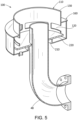
FIG. 4 is a perspective view of a lower end of a vent stack pipe that may be used with the steam discharge pipe blowback protection system ofFIG. 3 . -
FIG. 5 is a partial sectional view of the steam discharge pipe blowback system ofFIG. 3 with a slide plate in a closed or lowered position. -
FIG. 6 is a side plan view of the steam discharge pipe blowback system ofFIG. 3 with the slide plate in an open or raised position. - Referring now to the drawings, in which like numerals refer to like elements throughout the several views,
FIG. 1 is a schematic diagram of an exemplary embodiment of a combined cyclepower generation system 10. The combined cyclepower generation system 10 may include a gas turbine system, a steam turbine system, and a heat recovery steam generator (HRSG). Specifically, the combinedcycle system 10 may include agas turbine system 12 for driving afirst generator 14 to produce electrical power. Thegas turbine system 12 may include a turbine 16 (e.g., an expansion turbine), acombustor 18, and acompressor 20. The combinedcycle system 10 also may include asteam turbine system 22 for driving asecond generator 24. Thesteam turbine system 22 may include a low-pressure section 26 (LP ST), an intermediate-pressure section 28 (IP ST), and a high-pressure section 30 (HP ST). Although thegas turbine system 12 and thesteam turbine system 22 may driveseparate generators gas turbine system 12 and thesteam turbine system 22 also may be utilized in tandem to drive a single load via a single shaft. The generators and components described herein and the like may be incorporated into other types of power generation systems. - The combined
cycle system 10 also may include a multi-stage heatrecovery steam generator 32. Heated exhaust gas from thegas turbine system 12 may be directed into the heatrecovery steam generator 32 to heat the steam used to power thesteam turbine system 22. Specifically, the heatrecovery steam generator 32 may be fluidly connected and/or coupled with theturbine 16 via anexhaust channel 34 to provide exhaust fluid gases to the heatrecovery steam generator 32 to be utilized in generating and/or heating steam therein. Likewise, the heatrecovery steam generator 32 may be fluidly connected and/or coupled with the sections of thesteam turbine system 22 via one or more exhaust conduit(s) 40 to receive steam as well as one ormore supply conduits 42 to provide steam to sections of thesteam turbine system 22. - Exhaust from the low-
pressure section 26 of thesteam turbine 22 may be directed into acondenser 36. Condensate from thecondenser 36 may, in turn, be directed into a low-pressure section of the heatrecovery steam generator 32 with the aid of acondensate pump 38. One or more exhaust stacks 44 of the heatrecovery steam generator 32 may exhaust or release gas and/or fluid from heatrecovery steam generator 32 into the atmosphere. Other components and other configurations may be used herein. -
FIG. 2 shows an example of a portion of a knownexhaust stack 44. Theexhaust stack 44 may include asafety valve 46 attached to asteam discharge pipe 48. Thesteam discharge pipe 48 may have an elbow configuration 50. One end of thesteam discharge pipe 48 may be attached to thesafety valve 46 and the other end may extend into adrip pan 52 and avent stack pipe 54. Specifically, anexit end 56 of thesteam discharge pipe 48 may extend through thedrip pan 52 and into thevent stack pipe 54. As shown, the diameter of thesteam discharge pipe 48 is smaller than the diameter of thevent stack pipe 54, which has a diameter that is smaller than the diameter of thedrip pan 52. - As described above, steam may be vented into the
exhaust stack 44 during, for example, start-up procedures. The high temperature of the steam may cause a thermal mismatch between the high temperature components and the ambient temperature components until an equilibrium is reached. Moreover, a blowback of steam may allow the steam to escape between thedrip pan 52 and thevent stack pipe 54 when exiting thesteam discharge pipe 48 instead of being vented directly into thevent stack pipe 54. Specifically, the steam may flow through thesteam discharge pipe 48 into thevent stack pipe 54, where the steam reverses flow into thedrip pan 52. Because thedrip pan 52 is open at the top, this blowback of steam may create a hazardous situation for those nearby. -
FIGS. 3 and 4 show a steam discharge pipeblowback protection system 100 as may be described herein. The steam discharge pipeblowback protection system 100 may be used with thesteam discharge pipe 48 as described above or any source of a heated fluid. The steam discharge pipeblowback protection system 100 may include avent stack pipe 110. Theexit end 56 of thesteam discharge pipe 48 extends into thevent stack pipe 110. As described above, the diameter of thesteam discharge pipe 48 is smaller than the diameter of thevent stack pipe 110, and the diameter of thevent stack pipe 110 is smaller than the diameter of adrip pan 160, as discussed below. - In this example, the
vent stack pipe 110 may include a number ofapertures 120 at alower end 130 thereof. Theapertures 120 may be defined between a number offillets 140. Theapertures 120 may be largely rectangular 150 in shape and uniformly shaped, although any shape, any number, and any spacing may be used. Theapertures 120 may be formed in thelower end 130 of thevent stack pipe 110, or thelower end 130 may be a separate element that is joined to thevent stack pipe 110. Theapertures 120 on thelower end 130 of thevent stack pipe 110 are positioned inward of, or below, atop end wall 180 of thedrip pan 160, such that theapertures 120 are in fluid communication with the interior of thedrip pan 160. As shown inFIG. 3 , the end of thesteam discharge pipe 48 extends beyond (above) theapertures 120. - The
drip pan 160 may be positioned between thesteam discharge pipe 48 and thevent stack pipe 110. Thedrip pan 160 may have a bottom orfirst end wall 170 positioned about and radially outward from, thesteam discharge pipe 48, a top orsecond end wall 180 positioned about and joined to thevent stack pipe 110, and asidewall 190 extending between the twoend walls respective walls welds 200 or other types of permanent connection means. The bottom or thefirst end wall 170 may have asupport ledge 210 extending vertically therein (and parallel to the sidewall 190), which surrounds and is spaced apart from thesteam discharge pipe 48. Aslide plate 220 may be positioned on thesupport ledge 210. Theslide plate 220 may have acentral aperture 230 sized for the diameter of thesteam discharge pipe 48. Theslide plate 220 has a diameter less than the diameter of thedrip pan 160 but greater than the diameter of thevent stack pipe 110, such that theslide plate 220 is not capable of being sucked into thevent stack pipe 110 during operation. Theslide plate 220 may be maneuverable up and down thesteam discharge pipe 48 within confines of thewalls drip pan 160. When theslide plate 220 is positioned on thesupport ledge 210, theslide plate 220 and thelower end 130 of thevent stack pipe 54 may be separated by apredetermined clearance distance 240. - The bottom or the
first wall 170 of thedrip pan 160 may include adrain 250 formed therein. The top or thesecond end wall 180 may be welded or otherwise fixedly attached to thevent stack pipe 110. Other components and other configurations may be used herein. -
FIGS. 5 and6 show the steam discharge pipeblowback protection system 100 in operation. Once steam begins to flow into thesteam discharge pipe 48, there may be some eccentricity as thesteam discharge pipe 48, thevent stack pipe 110, and other components thermally expand until an equilibrium point is reached. Further, there may be some steam blowback. Specifically, the flow of steam may extend into thelower end 130 of thevent stack pipe 110 and may circulate turbulently through theapertures 120 therein and into plenum defined by thedrip pan 160. This turbulent flow causes a positive (i.e., greater than atmospheric) in pressure that will force theslide plate 220 downward against thesupport ledge 210 on thefirst wall 170 as is shown inFIGS. 3 and5 . This position effectively seals thedrip pan 160 and prevents the flow of steam from escaping therefrom. - After the blowback, a normal or laminar flow of steam may extend through the
vent stack pipe 110. As an equilibrium (steady state) condition is reached, this normal flow will decrease the pressure within thedrip pan 160 below atmospheric pressure (i.e., to a negative pressure). The reduction in pressure will allow theslide plate 220 to be drawn off thesupport ledge 210 along thesteam discharge pipe 48 as is shown inFIG. 6 . A flow of ambient air then may be forced into thedrip pan 160 and may be entrained into the flow of steam. Specifically, air flows between thesteam discharge pipe 48 and thesupport ledge 210 into the gap between the raisedslide plate 220 and the top of thesupport ledge 210 and into the plenum defined by thewall drip pan 160. Air can enter thevent stack pipe 110 via theapertures 120 in thelower end 130 thereof and become entrained with the steam flow. The entrained air flow provides a layer of film along the interior of thevent stack pipe 110 and ensures that shock waves within the flow of steam are buffered from the wall of thevent stack pipe 110. - The steam discharge pipe
blowback protection system 100 thus helps alleviate the complex connections of the components in theexhaust stack 44 by allowing for position mismatch. Likewise, the steam discharge pipeblowback protection system 100 protects against steam blowback escaping therefrom. Further, after this moment of blowback, the steam discharge pipeblowback protection system 100 then allow air to be entrained into the flow of steam for overall stable operation. - It should be apparent that the foregoing relates only to certain embodiments of this application and resultant patent. Numerous changes and modifications may be made herein by one of ordinary skill in the art without departing from the general spirit and scope of the disclosure as defined by the following claims and the equivalents thereof.
- Further aspects of the present steam discharge pipe blowback protection system are provided by the subject matter of the following clauses:
- 1. A steam discharge pipe blowback protection system for use with a steam discharge pipe and a flow of steam therethrough, comprising a vent stack pipe and a drip pan, wherein an exit end of the steam discharge pipe extends through the drip pan and into the vent stack pipe, wherein the drip pan comprises a slide plate positioned around the steam discharge pipe, and wherein a blowback in the flow of steam causes the slide plate to seal the drip pan.
- 2. The steam discharge pipe blowback protection system of any preceding clause, wherein, after the blowback in the flow of steam, the slide plate is configured to rise along the steam discharge pipe and allow a flow of ambient air into the drip pan.
- 3. The steam discharge pipe blowback protection system of any preceding clause, wherein the vent stack pipe comprises a plurality of apertures positioned in a lower end thereof.
- 4. The steam discharge pipe blowback protection system of any preceding clause, wherein the plurality of apertures of the vent stack pipe are positioned within the drip pan.
- 5. The steam discharge pipe blowback protection system of any preceding clause, wherein each aperture of the plurality of apertures of the vent stack pipe comprises a rectangular shape.
- 6. The steam discharge pipe blowback protection system of any preceding clause, wherein the plurality of apertures of the vent stack pipe are separated by a plurality of fillets.
- 7. The steam discharge pipe blowback protection system of any preceding clause, wherein the vent stack pipe and the drip pan are welded together.
- 8. The steam discharge pipe blowback protection system of any preceding clause, wherein the drip pan comprises a first end wall, a second end wall opposite the first end wall, and a sidewall connecting the first end wall and the second end wall.
- 9. The steam discharge pipe blowback protection system of any preceding clause, wherein the first wall comprises a support ledge configured to support the slide plate.
- 10. The steam discharge pipe blowback protection system of any preceding clause, wherein the first end wall comprises a drain therein.
- 11. The steam discharge pipe blowback protection system of any preceding clause, wherein the first end wall, the second end wall, the sidewall, and the support ledge are welded together.
- 12. The steam discharge pipe blowback protection system of any preceding clause, wherein the slide plate comprises a central aperture sized to accommodate the steam discharge pipe..
- 13. The steam discharge pipe blowback protection system of any preceding clause, wherein aperture sized to accommodate the steam discharge pipe. the vent stack pipe and the slide plate are separated by a predetermined clearance distance.
- 14. A method of flowing steam from a steam discharge pipe through a drip pan and into a vent stack pipe, the method comprising: initiating a flow of steam through the steam discharge pipe; receiving a blowback of steam from the steam discharge pipe into the drip pan, wherein the blowback of steam creates a positive pressure inside the drip pan and forces a slide plate to seal the drip pan; flowing an additional flow of steam into the vent stack pipe to achieve a steady state, wherein the additional flow of steam creates a negative pressure inside the drip pan and forces the slide plate to open the drip pan; and flowing ambient air into the flow of steam in the vent stack pipe.
- 15. A heat recovery steam generator with a flow of steam therethrough, comprising a steam discharge pipe to vent the flow of steam, a vent stack pipe to receive the flow of steam from the steam discharge pipe, and a drip pan surrounding the steam discharge pipe and the vent stack pipe, wherein the drip pan comprises a slide plate positioned around the steam discharge pipe, and wherein a blowback in the flow of steam causes the slide plate to seal the drip pan.
- 16. The heat recovery steam generator of any preceding clause, wherein, after the blowback in the flow of steam, the slide plate is configured to rise along the steam discharge pipe and allow a flow of ambient air into the drip pan.
- 17. The heat recovery steam generator of any preceding clause, wherein the vent stack pipe comprises a plurality of apertures positioned in a lower end thereof within the drip pan.
- 18. The heat recovery steam generator of any preceding clause, wherein the drip pan comprises a first end wall, a second end wall opposite the first end wall, and a sidewall connecting the first end wall and the second end wall; and wherein the first end wall comprises a support ledge configured to support the slide plate.
- 19. The heat recovery steam generator of any preceding clause, wherein the slide plate comprises a central aperture and wherein the central aperture of the slide plate is sized to accommodate the steam discharge pipe.
Claims (14)
- A steam discharge pipe blowback protection system (100) for use with a steam discharge pipe (48) and a flow of steam therethrough, comprising:a vent stack pipe (110); anda drip pan (160);wherein an exit end (56) of the steam discharge pipe (48) extends through the drip pan (160) and into the vent stack pipe (110);wherein the drip pan (160) comprises a slide plate (220) positioned around the steam discharge pipe (48); andwherein a blowback in the flow of steam causes the slide plate (220) to seal the drip pan (160).
- The steam discharge pipe blowback protection system (100) of claim 1, wherein, after the blowback in the flow of steam, the slide plate (220) is configured to rise along the steam discharge pipe (48) and allow a flow of ambient air into the drip pan (160).
- The steam discharge pipe blowback protection system (100) of claim 1, wherein the vent stack pipe (110) comprises a plurality of apertures (120) positioned in a lower end (130) thereof.
- The steam discharge pipe blowback protection system (100) of claim 3, wherein the plurality of apertures (120) of the vent stack pipe (110) are positioned within the drip pan (160).
- The steam discharge pipe blowback protection system (100) of claim 3, wherein each aperture of the plurality of apertures (120) of the vent stack pipe (110) comprises a rectangular shape (150).
- The steam discharge pipe blowback protection system (100) of claim 3, wherein the plurality of apertures (120) of the vent stack pipe (110) are separated by a plurality of fillets (140).
- The steam discharge pipe blowback protection system (100) of claim 1, wherein the vent stack pipe (110) and the drip pan (160) are welded together.
- The steam discharge pipe blowback protection system (100) of claim 1, wherein the drip pan (160) comprises a first end wall (170), a second end wall (180) opposite the first end wall, and a sidewall (190) connecting the first end wall (170) and the second end wall (180).
- The steam discharge pipe blowback protection system (100) of claim 8, wherein the first end wall (170) comprises a support ledge (210) configured to support the slide plate (220).
- The steam discharge pipe blowback protection system (100) of claim 8, wherein the first end wall (170) comprises a drain (250) therein.
- The steam discharge pipe blowback protection system (100) of claim 9, wherein the first end wall (170), the second end wall (180), the sidewall (190), and the support ledge (210) are welded together.
- The steam discharge pipe blowback protection system (100) of claim 1, wherein the slide plate (220) comprises a central aperture (230) sized to accommodate the steam discharge pipe (48).
- The steam discharge pipe blowback protection system (100) of claim 1, wherein, when the blowback in the flow of steam is not occurring, the vent stack pipe (110) and the slide plate (220) are separated by a predetermined clearance distance (240).
- A method of flowing steam from a steam discharge pipe (48) through a drip pan (160) and into a vent stack pipe (110), comprising:initiating a flow of steam through the steam discharge pipe (48),receiving a blowback of steam from the steam discharge pipe (48) into the drip pan (160), wherein the blowback of steam creates a positive pressure inside the drip pan and forces a slide plate (220) to seal the drip pan (160);flowing an additional flow of steam into the vent stack pipe (110) to achieve a steady state, wherein the flow of steam creates a negative pressure inside the drip pan (160) and forces the slide plate (220) to open the drip pan (160); andflowing ambient air into the flow of steam in the vent stack pipe (110).
Applications Claiming Priority (1)
| Application Number | Priority Date | Filing Date | Title |
|---|---|---|---|
| US18/323,711 US12116907B1 (en) | 2023-05-25 | 2023-05-25 | Steam discharge pipe blowback protection system |
Publications (1)
| Publication Number | Publication Date |
|---|---|
| EP4474625A1 true EP4474625A1 (en) | 2024-12-11 |
Family
ID=90970743
Family Applications (1)
| Application Number | Title | Priority Date | Filing Date |
|---|---|---|---|
| EP24173613.1A Pending EP4474625A1 (en) | 2023-05-25 | 2024-04-30 | Steam discharge pipe blowback protection system |
Country Status (4)
| Country | Link |
|---|---|
| US (1) | US12116907B1 (en) |
| EP (1) | EP4474625A1 (en) |
| JP (1) | JP2024170297A (en) |
| KR (1) | KR20240170487A (en) |
Citations (5)
| Publication number | Priority date | Publication date | Assignee | Title |
|---|---|---|---|---|
| JPS5288824A (en) * | 1976-01-21 | 1977-07-25 | Babcock Hitachi Kk | Safety valve drip pan providing safety device |
| JPS5597574A (en) * | 1979-01-17 | 1980-07-24 | Babcock Hitachi Kk | Safety valve drip pan device |
| KR200323381Y1 (en) * | 2003-05-23 | 2003-08-14 | 두산중공업 주식회사 | Drip Pan Equipment For Backward Flow Prevention Of Safety Valve Discharge Pipe |
| KR20040100363A (en) * | 2003-05-22 | 2004-12-02 | 두산중공업 주식회사 | The Support Apparatus of Safety Valve's Outlet Vent Line |
| KR20180010037A (en) * | 2016-07-20 | 2018-01-30 | 현대중공업 주식회사 | Drip pan apparatus |
Family Cites Families (6)
| Publication number | Priority date | Publication date | Assignee | Title |
|---|---|---|---|---|
| US4416581A (en) * | 1982-02-16 | 1983-11-22 | Elliott Turbomachinery Co., Inc. | Method and apparatus for cooling an expander |
| US4493608A (en) * | 1982-12-27 | 1985-01-15 | General Electric Company | Surge control in compressor |
| US10415433B2 (en) * | 2016-12-12 | 2019-09-17 | General Electric Company | Systems and methods for reducing thermal stress in pressure vessels |
| US11060421B2 (en) * | 2017-12-04 | 2021-07-13 | General Electric Company | System to aggregate working fluid for heat recovery steam generators |
| US10619519B2 (en) | 2017-12-06 | 2020-04-14 | General Electric Company | Bypass conduits for reducing thermal fatigue and stress in heat recovery steam generators of combined cycle power plant systems |
| US11448160B2 (en) | 2019-09-23 | 2022-09-20 | General Electric Company | High temperature gradient gas mixer |
-
2023
- 2023-05-25 US US18/323,711 patent/US12116907B1/en active Active
-
2024
- 2024-04-30 EP EP24173613.1A patent/EP4474625A1/en active Pending
- 2024-05-15 JP JP2024079706A patent/JP2024170297A/en active Pending
- 2024-05-27 KR KR1020240068473A patent/KR20240170487A/en active Pending
Patent Citations (5)
| Publication number | Priority date | Publication date | Assignee | Title |
|---|---|---|---|---|
| JPS5288824A (en) * | 1976-01-21 | 1977-07-25 | Babcock Hitachi Kk | Safety valve drip pan providing safety device |
| JPS5597574A (en) * | 1979-01-17 | 1980-07-24 | Babcock Hitachi Kk | Safety valve drip pan device |
| KR20040100363A (en) * | 2003-05-22 | 2004-12-02 | 두산중공업 주식회사 | The Support Apparatus of Safety Valve's Outlet Vent Line |
| KR200323381Y1 (en) * | 2003-05-23 | 2003-08-14 | 두산중공업 주식회사 | Drip Pan Equipment For Backward Flow Prevention Of Safety Valve Discharge Pipe |
| KR20180010037A (en) * | 2016-07-20 | 2018-01-30 | 현대중공업 주식회사 | Drip pan apparatus |
Also Published As
| Publication number | Publication date |
|---|---|
| US12116907B1 (en) | 2024-10-15 |
| JP2024170297A (en) | 2024-12-06 |
| KR20240170487A (en) | 2024-12-03 |
Similar Documents
| Publication | Publication Date | Title |
|---|---|---|
| US8359824B2 (en) | Heat recovery steam generator for a combined cycle power plant | |
| US20060254280A1 (en) | Combined cycle power plant using compressor air extraction | |
| EP3354865A1 (en) | Steam turbine preheating system with a steam generator | |
| US8157512B2 (en) | Heat pipe intercooler for a turbomachine | |
| EP2141336A2 (en) | Systems and methods for supplying cooling air to a gas turbine | |
| EP3524779B1 (en) | Tail bearing housing | |
| US20100054926A1 (en) | System and method for thermal management of a gas turbine inlet | |
| US11473445B2 (en) | Steam turbine plant and cooling method for same | |
| US9810094B2 (en) | Steam turbine forced air cooling system, equipment, and steam turbine equipped with it | |
| EP2752558A2 (en) | Articulated transition duct in turbomachine | |
| US20140331671A1 (en) | Water/steam cycle and method for operating the same | |
| EP2589750A2 (en) | Method For Controlling Gas Turbine Rotor Temperature During Periods Of Extended Downtime | |
| US12116907B1 (en) | Steam discharge pipe blowback protection system | |
| KR102462735B1 (en) | Systems and methods for reducing thermal stress in pressure vessels | |
| US20180135467A1 (en) | Cooling of gas turbine at varying loads | |
| CN106133293B (en) | Gas turbine | |
| EP2604803A2 (en) | Steam seal header, method of using a steam seal header and steam turbine system incorporating a steam seal header | |
| JP7833267B2 (en) | Gland steam condenser for combined cycle power plants and its operating method | |
| JP7652462B2 (en) | A reaction turbine that runs on condensing steam | |
| US11326520B2 (en) | Heat exchange apparatus and gas turbine having the same | |
| JP2015096800A (en) | Long-life exhaust heat recovery boiler unit reinforced inside | |
| Radin et al. | Aspects of the Capacity-Enhancing Modernization of F-Series Gas Turbine Plants and the Characteristics of Single-Shaft Combined-Cycle Gas Plant | |
| EP2149682A1 (en) | Condenser for a combined cycle power plant | |
| EP3159497A1 (en) | System and method for wheel space temperature management | |
| CN109804140B (en) | Steam and gas turbine installation |
Legal Events
| Date | Code | Title | Description |
|---|---|---|---|
| PUAI | Public reference made under article 153(3) epc to a published international application that has entered the european phase |
Free format text: ORIGINAL CODE: 0009012 |
|
| STAA | Information on the status of an ep patent application or granted ep patent |
Free format text: STATUS: THE APPLICATION HAS BEEN PUBLISHED |
|
| AK | Designated contracting states |
Kind code of ref document: A1 Designated state(s): AL AT BE BG CH CY CZ DE DK EE ES FI FR GB GR HR HU IE IS IT LI LT LU LV MC ME MK MT NL NO PL PT RO RS SE SI SK SM TR |
|
| STAA | Information on the status of an ep patent application or granted ep patent |
Free format text: STATUS: REQUEST FOR EXAMINATION WAS MADE |
|
| 17P | Request for examination filed |
Effective date: 20250610 |
|
| RAP3 | Party data changed (applicant data changed or rights of an application transferred) |
Owner name: GE VERNOVA TECHNOLOGY GMBH |