EP4474622A1 - Aircraft engine oil distribution system - Google Patents
Aircraft engine oil distribution system Download PDFInfo
- Publication number
- EP4474622A1 EP4474622A1 EP24181099.3A EP24181099A EP4474622A1 EP 4474622 A1 EP4474622 A1 EP 4474622A1 EP 24181099 A EP24181099 A EP 24181099A EP 4474622 A1 EP4474622 A1 EP 4474622A1
- Authority
- EP
- European Patent Office
- Prior art keywords
- oil
- cooling fluid
- distribution system
- oil reservoir
- aircraft engine
- Prior art date
- Legal status (The legal status is an assumption and is not a legal conclusion. Google has not performed a legal analysis and makes no representation as to the accuracy of the status listed.)
- Pending
Links
Images



Classifications
-
- F—MECHANICAL ENGINEERING; LIGHTING; HEATING; WEAPONS; BLASTING
- F01—MACHINES OR ENGINES IN GENERAL; ENGINE PLANTS IN GENERAL; STEAM ENGINES
- F01D—NON-POSITIVE DISPLACEMENT MACHINES OR ENGINES, e.g. STEAM TURBINES
- F01D25/00—Component parts, details, or accessories, not provided for in, or of interest apart from, other groups
- F01D25/08—Cooling; Heating; Heat-insulation
- F01D25/12—Cooling
- F01D25/125—Cooling of bearings
-
- F—MECHANICAL ENGINEERING; LIGHTING; HEATING; WEAPONS; BLASTING
- F02—COMBUSTION ENGINES; HOT-GAS OR COMBUSTION-PRODUCT ENGINE PLANTS
- F02C—GAS-TURBINE PLANTS; AIR INTAKES FOR JET-PROPULSION PLANTS; CONTROLLING FUEL SUPPLY IN AIR-BREATHING JET-PROPULSION PLANTS
- F02C7/00—Features, components parts, details or accessories, not provided for in, or of interest apart form groups F02C1/00 - F02C6/00; Air intakes for jet-propulsion plants
- F02C7/06—Arrangements of bearings; Lubricating
-
- F—MECHANICAL ENGINEERING; LIGHTING; HEATING; WEAPONS; BLASTING
- F01—MACHINES OR ENGINES IN GENERAL; ENGINE PLANTS IN GENERAL; STEAM ENGINES
- F01D—NON-POSITIVE DISPLACEMENT MACHINES OR ENGINES, e.g. STEAM TURBINES
- F01D25/00—Component parts, details, or accessories, not provided for in, or of interest apart from, other groups
- F01D25/18—Lubricating arrangements
-
- F—MECHANICAL ENGINEERING; LIGHTING; HEATING; WEAPONS; BLASTING
- F01—MACHINES OR ENGINES IN GENERAL; ENGINE PLANTS IN GENERAL; STEAM ENGINES
- F01M—LUBRICATING OF MACHINES OR ENGINES IN GENERAL; LUBRICATING INTERNAL COMBUSTION ENGINES; CRANKCASE VENTILATING
- F01M11/00—Component parts, details or accessories, not provided for in, or of interest apart from, groups F01M1/00 - F01M9/00
- F01M11/0004—Oilsumps
-
- F—MECHANICAL ENGINEERING; LIGHTING; HEATING; WEAPONS; BLASTING
- F02—COMBUSTION ENGINES; HOT-GAS OR COMBUSTION-PRODUCT ENGINE PLANTS
- F02C—GAS-TURBINE PLANTS; AIR INTAKES FOR JET-PROPULSION PLANTS; CONTROLLING FUEL SUPPLY IN AIR-BREATHING JET-PROPULSION PLANTS
- F02C7/00—Features, components parts, details or accessories, not provided for in, or of interest apart form groups F02C1/00 - F02C6/00; Air intakes for jet-propulsion plants
- F02C7/12—Cooling of plants
- F02C7/14—Cooling of plants of fluids in the plant, e.g. lubricant or fuel
-
- F—MECHANICAL ENGINEERING; LIGHTING; HEATING; WEAPONS; BLASTING
- F02—COMBUSTION ENGINES; HOT-GAS OR COMBUSTION-PRODUCT ENGINE PLANTS
- F02C—GAS-TURBINE PLANTS; AIR INTAKES FOR JET-PROPULSION PLANTS; CONTROLLING FUEL SUPPLY IN AIR-BREATHING JET-PROPULSION PLANTS
- F02C7/00—Features, components parts, details or accessories, not provided for in, or of interest apart form groups F02C1/00 - F02C6/00; Air intakes for jet-propulsion plants
- F02C7/12—Cooling of plants
- F02C7/16—Cooling of plants characterised by cooling medium
-
- F—MECHANICAL ENGINEERING; LIGHTING; HEATING; WEAPONS; BLASTING
- F02—COMBUSTION ENGINES; HOT-GAS OR COMBUSTION-PRODUCT ENGINE PLANTS
- F02C—GAS-TURBINE PLANTS; AIR INTAKES FOR JET-PROPULSION PLANTS; CONTROLLING FUEL SUPPLY IN AIR-BREATHING JET-PROPULSION PLANTS
- F02C7/00—Features, components parts, details or accessories, not provided for in, or of interest apart form groups F02C1/00 - F02C6/00; Air intakes for jet-propulsion plants
- F02C7/22—Fuel supply systems
- F02C7/224—Heating fuel before feeding to the burner
-
- F—MECHANICAL ENGINEERING; LIGHTING; HEATING; WEAPONS; BLASTING
- F16—ENGINEERING ELEMENTS AND UNITS; GENERAL MEASURES FOR PRODUCING AND MAINTAINING EFFECTIVE FUNCTIONING OF MACHINES OR INSTALLATIONS; THERMAL INSULATION IN GENERAL
- F16N—LUBRICATING
- F16N39/00—Arrangements for conditioning of lubricants in the lubricating system
- F16N39/002—Arrangements for conditioning of lubricants in the lubricating system by deaeration
-
- F—MECHANICAL ENGINEERING; LIGHTING; HEATING; WEAPONS; BLASTING
- F16—ENGINEERING ELEMENTS AND UNITS; GENERAL MEASURES FOR PRODUCING AND MAINTAINING EFFECTIVE FUNCTIONING OF MACHINES OR INSTALLATIONS; THERMAL INSULATION IN GENERAL
- F16N—LUBRICATING
- F16N39/00—Arrangements for conditioning of lubricants in the lubricating system
- F16N39/02—Arrangements for conditioning of lubricants in the lubricating system by cooling
-
- F—MECHANICAL ENGINEERING; LIGHTING; HEATING; WEAPONS; BLASTING
- F16—ENGINEERING ELEMENTS AND UNITS; GENERAL MEASURES FOR PRODUCING AND MAINTAINING EFFECTIVE FUNCTIONING OF MACHINES OR INSTALLATIONS; THERMAL INSULATION IN GENERAL
- F16N—LUBRICATING
- F16N7/00—Arrangements for supplying oil or unspecified lubricant from a stationary reservoir or the equivalent in or on the machine or member to be lubricated
- F16N7/38—Arrangements for supplying oil or unspecified lubricant from a stationary reservoir or the equivalent in or on the machine or member to be lubricated with a separate pump; Central lubrication systems
- F16N7/40—Arrangements for supplying oil or unspecified lubricant from a stationary reservoir or the equivalent in or on the machine or member to be lubricated with a separate pump; Central lubrication systems in a closed circulation system
-
- F—MECHANICAL ENGINEERING; LIGHTING; HEATING; WEAPONS; BLASTING
- F01—MACHINES OR ENGINES IN GENERAL; ENGINE PLANTS IN GENERAL; STEAM ENGINES
- F01M—LUBRICATING OF MACHINES OR ENGINES IN GENERAL; LUBRICATING INTERNAL COMBUSTION ENGINES; CRANKCASE VENTILATING
- F01M11/00—Component parts, details or accessories, not provided for in, or of interest apart from, groups F01M1/00 - F01M9/00
- F01M11/0004—Oilsumps
- F01M2011/0025—Oilsumps with heat exchangers
-
- F—MECHANICAL ENGINEERING; LIGHTING; HEATING; WEAPONS; BLASTING
- F05—INDEXING SCHEMES RELATING TO ENGINES OR PUMPS IN VARIOUS SUBCLASSES OF CLASSES F01-F04
- F05D—INDEXING SCHEME FOR ASPECTS RELATING TO NON-POSITIVE-DISPLACEMENT MACHINES OR ENGINES, GAS-TURBINES OR JET-PROPULSION PLANTS
- F05D2230/00—Manufacture
- F05D2230/30—Manufacture with deposition of material
- F05D2230/31—Layer deposition
-
- F—MECHANICAL ENGINEERING; LIGHTING; HEATING; WEAPONS; BLASTING
- F05—INDEXING SCHEMES RELATING TO ENGINES OR PUMPS IN VARIOUS SUBCLASSES OF CLASSES F01-F04
- F05D—INDEXING SCHEME FOR ASPECTS RELATING TO NON-POSITIVE-DISPLACEMENT MACHINES OR ENGINES, GAS-TURBINES OR JET-PROPULSION PLANTS
- F05D2260/00—Function
- F05D2260/20—Heat transfer, e.g. cooling
- F05D2260/213—Heat transfer, e.g. cooling by the provision of a heat exchanger within the cooling circuit
-
- F—MECHANICAL ENGINEERING; LIGHTING; HEATING; WEAPONS; BLASTING
- F05—INDEXING SCHEMES RELATING TO ENGINES OR PUMPS IN VARIOUS SUBCLASSES OF CLASSES F01-F04
- F05D—INDEXING SCHEME FOR ASPECTS RELATING TO NON-POSITIVE-DISPLACEMENT MACHINES OR ENGINES, GAS-TURBINES OR JET-PROPULSION PLANTS
- F05D2260/00—Function
- F05D2260/20—Heat transfer, e.g. cooling
- F05D2260/221—Improvement of heat transfer
- F05D2260/2214—Improvement of heat transfer by increasing the heat transfer surface
- F05D2260/22141—Improvement of heat transfer by increasing the heat transfer surface using fins or ribs
-
- F—MECHANICAL ENGINEERING; LIGHTING; HEATING; WEAPONS; BLASTING
- F05—INDEXING SCHEMES RELATING TO ENGINES OR PUMPS IN VARIOUS SUBCLASSES OF CLASSES F01-F04
- F05D—INDEXING SCHEME FOR ASPECTS RELATING TO NON-POSITIVE-DISPLACEMENT MACHINES OR ENGINES, GAS-TURBINES OR JET-PROPULSION PLANTS
- F05D2260/00—Function
- F05D2260/20—Heat transfer, e.g. cooling
- F05D2260/232—Heat transfer, e.g. cooling characterized by the cooling medium
-
- F—MECHANICAL ENGINEERING; LIGHTING; HEATING; WEAPONS; BLASTING
- F05—INDEXING SCHEMES RELATING TO ENGINES OR PUMPS IN VARIOUS SUBCLASSES OF CLASSES F01-F04
- F05D—INDEXING SCHEME FOR ASPECTS RELATING TO NON-POSITIVE-DISPLACEMENT MACHINES OR ENGINES, GAS-TURBINES OR JET-PROPULSION PLANTS
- F05D2260/00—Function
- F05D2260/60—Fluid transfer
- F05D2260/609—Deoiling or demisting
-
- F—MECHANICAL ENGINEERING; LIGHTING; HEATING; WEAPONS; BLASTING
- F05—INDEXING SCHEMES RELATING TO ENGINES OR PUMPS IN VARIOUS SUBCLASSES OF CLASSES F01-F04
- F05D—INDEXING SCHEME FOR ASPECTS RELATING TO NON-POSITIVE-DISPLACEMENT MACHINES OR ENGINES, GAS-TURBINES OR JET-PROPULSION PLANTS
- F05D2260/00—Function
- F05D2260/98—Lubrication
-
- F—MECHANICAL ENGINEERING; LIGHTING; HEATING; WEAPONS; BLASTING
- F16—ENGINEERING ELEMENTS AND UNITS; GENERAL MEASURES FOR PRODUCING AND MAINTAINING EFFECTIVE FUNCTIONING OF MACHINES OR INSTALLATIONS; THERMAL INSULATION IN GENERAL
- F16N—LUBRICATING
- F16N2210/00—Applications
- F16N2210/02—Turbines
-
- F—MECHANICAL ENGINEERING; LIGHTING; HEATING; WEAPONS; BLASTING
- F16—ENGINEERING ELEMENTS AND UNITS; GENERAL MEASURES FOR PRODUCING AND MAINTAINING EFFECTIVE FUNCTIONING OF MACHINES OR INSTALLATIONS; THERMAL INSULATION IN GENERAL
- F16N—LUBRICATING
- F16N2210/00—Applications
- F16N2210/08—Aircraft
Definitions
- the invention relates generally to oil distribution systems and, more particularly, to oil distribution systems for an aircraft engine.
- an aircraft engine oil distribution system including a system container having one or more walls enclosing an internal volume, an oil reservoir disposed in the internal volume of the system container and defining an oil-receiving cavity therein for storing liquid oil and a mist of air and oil, the oil reservoir having a plurality of fins protruding from an inner surface of a wall of the oil reservoir and extending into the oil-receiving cavity, and a heat exchanger disposed in the internal volume of the system container.
- the heat exchanger includes a cooling fluid passage extending between a cooling fluid inlet and a cooling fluid outlet, the cooling fluid passage defined between the one or more walls of the system container and the wall of the oil reservoir and permitting flow of a cooling fluid therein, and a matrix disposed in the cooling fluid passage in heat transfer relationship with the plurality of fins of the oil reservoir.
- the aircraft engine oil distribution system as defined above and described herein may also include one or more of the following features, in whole or in part, and in any combination.
- the cooling fluid passage is defined between a bottom wall of the system container and a bottom wall of the oil reservoir, between a sidewall of the system container and the wall of the oil reservoir, and between a top wall of the system container and a top wall of the oil reservoir.
- the cooling fluid inlet is located closer to the bottom wall of the system container than the top wall of the system container, and the cooling fluid flows upwardly in the cooling fluid passage.
- the plurality of fins is connected to the matrix of the heat exchanger for transferring heat from the oil located in the oil reservoir to the matrix by thermal conduction.
- the matrix includes at least one of microchannels, a lattice structure, and gyroid structures.
- a deaerator separates air from oil upon entry in the oil reservoir and to feed hot deaerated oil into the oil reservoir.
- the deaerator is rotating and spills hot deaerated oil on the wall of the oil reservoir and the plurality of fins upon rotation thereof.
- the cooling fluid is selected from a group comprising liquid ammonia, liquid methane, liquid propane, liquid butane, supercritical carbon dioxide, and liquid hydrogen.
- the cooling fluid is adapted for use in a turboexpander.
- the oil flows upwardly between the oil inlet and the oil outlet.
- the oil flows upwardly in the oil passage.
- the oil flow is then distributed between different components in need of oil.
- These components may include, for instance, one or more bearing cavity(ies) 22, a generator, an actuator, and/or a gearbox 23, which may correspond to the reduction gearbox of Fig. 1 or any other gearbox of the engine, in some embodiments.
- Used oil is then scavenged and scavenge pumps 36 drive a scavenge oil flow F2 from scavenge outlets of the bearing cavities 22 and the gearbox 23 back to the oil reservoir 31b where the oil may be flown back to the oil pump 34.
- the oil reservoir 31b has a volume devoid of oil (e.g, empty space containing a mist of air and oil). During lubrication, the oil is expected to be mixed with air.
- a portion of the oil distribution system 30 is schematically shown, and includes the system container 31a, the oil reservoir 31b and the heat exchanger 40.
- the system container 31a has, when positioned for use, a top wall 50a, a bottom wall 52a and a sidewall 54a.
- the system container 31a has a plurality of sidewalls 54a.
- the top wall 50a, the bottom wall 52a and the sidewall 54a enclose an internal volume of the system container 31a.
- a cooling fluid manifold 58 is connected to the top wall 50a of the system container 31a and is fluidly connected to a cooling fluid outlet 60 of the heat exchanger 40.
- the cooling fluid manifold 58 and the cooling fluid outlet 60 collect the cooling fluid 42 that has been warmed during its flow through the heat exchanger 40 and allow the warmed cooling fluid 42 to exit the system container 31a.
- Each fin 64 of the plurality of fins 64 is scooped-shaped and configured for permitting the oil from dripping from an upper fin to a lower fin (i.e. located below the upper fin).
- the hot oil flows on the plurality of fins 64 in a cascading motion, downwardly over the plurality of fins 64 until reaching the level L of liquid oil in the oil reservoir 31b, as depicted by arrows 65 in Fig. 3 .
- Having the oil dripping from upper to lower fins increases the travel time of the hot oil between the oil manifold 62 and the bottom of the oil reservoir 31b, which may increase the amount of heat transferred from the oil to the cooling fluid 42.
- the plurality of fins 64 could be shaped otherwise in other implementations, and could be flat for instance.
- the plurality of fins 64 could also extend from an inner-surface of the top wall 50b and/or of the bottom wall 52b.
- the heat exchanger 40 further includes a matrix 66 disposed in the cooling fluid passage 48.
- the matrix 66 is located between the sidewalls 54a, 54b.
- the matrix 66 is connected to the sidewalls 54a, 54b, and to the plurality of fins 64.
- the matrix 66 is connected to at least one of the sidewall 54a, sidewall 54b, and the plurality of fins 64. Regardless of how the matrix 66 is connected to at least one of the sidewall 54a, sidewall 54b, and the plurality of fins 64, the matrix 66 is in a heat transfer relationship with the plurality of fins 64, whether via conductive heat transfer, convective heat transfer, radiation heat transfer or a combination thereof.
- the matrix 66 includes one or a combination of structures such as microchannels, a lattice structure, and gyroid structures, each having relatively high surface area per volume of the matrix 66, hence increasing heat transfer capabilities of the heat exchanger 40.
- the matrix 66 is schematically represented in the Figures, and may differ in scale/shape in different embodiments.
- the cooling fluid 42 flows in a direction opposite the flow of oil in the oil reservoir 31b, that is upwardly from the cooling fluid inlet 56, through the cooling fluid passage 48 and the matrix 66, and on to the cooling fluid manifold 58 and the cooling fluid outlet 60.
- the cooling fluid 42 and oil are thus flowing in opposite directions in the oil distribution system 30, which may further increase the heat transfer therebetween.
- hot oil flowing from the oil manifold 62 enters the oil reservoir 31b and drips from an upper fin 64 to a lower fin 64 (as depicted by arrows 65) and along the sidewall 54b of the oil reservoir 31b until reaching the liquid oil at the bottom of the oil reservoir 31b.
- the oil flows downwardly, the oil is cooled upon contacting the fins 64 and the sidewall 54b being cooled by the cooling fluid 42 pumped by pump 44 and flowing upwardly in the cooling fluid passage 48 and through the matrix 66.
- the cooling fluid 42 flows between the bottom walls 52a, 52b and also cools the liquid oil present at the bottom of the oil reservoir 31b.
- the warmed cooling fluid 42 flows upwardly between the cooling fluid inlet 56 and the cooling fluid outlet 60, as depicted by arrows 70.
- the oil distribution system 130 further includes the deaerator 38 located in an upper portion of the oil reservoir 31b. Put differently, the deaerator is located closer to the top wall 50b of the oil reservoir 31b than the bottom wall 52b.
- the deaerator 38 separates air from oil upon entry of the hot oil via the oil manifold 62 in the oil-receiving cavity of the oil reservoir 31b, and the deaerator 38 feeds hot deaerated oil into the oil reservoir 31b.
- the deaerator 38 rotates and spills hot deaerated oil on a larger portion of the sidewall 54b and on several fins 64 upon rotation thereof. Since the hot deaerated oil is projected on a larger portion of the sidewall 54b and on several fins 64 simultaneously, heat transfer between the oil and the cooling fluid 42 is increased as the hot oil is in contact with more surface area of the sidewall 54b and fins 64. The deaerated oil then flows from an upper fin 64 to a lower fin 64 and on the sidewall 54b in a cascading motion, as depicted by arrows 65, until reaching the liquid oil at the bottom of the oil reservoir 31b. It is also contemplated that the deaerator 38 could be static in other implementations.
- the heat exchanger 40 disposed in the system container 31a has an intermediate wall 54c located between the top wall 50a of the system container 31a and the top wall of the oil reservoir 31b, between the bottom wall 52a of the system container 31a and the bottom wall 52b of the oil reservoir 31b, and between the sidewall 54a of the system container 31a and the sidewall 54b of the oil reservoir 31b.
- hot oil flows upwardly in the oil passage 62b between the oil inlet 62a and the oil outlet 62c, as depicted by arrows 365.
- the cooling fluid 42 also flows upwardly in the cooling fluid passage 48 and contacts the matrix 66. It is noted in this implementation that both the oil and the cooling fluid 42 flow upwardly along the sidewalls 54a, 54b in their respective passages 62b, 48, as depicted by arrows 365, 370.
- Heat is transferred from the oil to the cooling fluid 42 upon contact thereof with the intermediate wall 54c and the matrix 66.
- the cooled oil enters the oil reservoir 31b.
Landscapes
- Engineering & Computer Science (AREA)
- General Engineering & Computer Science (AREA)
- Mechanical Engineering (AREA)
- Chemical & Material Sciences (AREA)
- Combustion & Propulsion (AREA)
- Lubrication Of Internal Combustion Engines (AREA)
- Lubrication Details And Ventilation Of Internal Combustion Engines (AREA)
Abstract
An aircraft engine (10) oil distribution system (30) includes a system container (31a), an oil reservoir (31b) disposed in the system container (31a), the oil reservoir (31b) having a plurality of fins (64) protruding from an inner-surface of a wall of the oil reservoir (31b) and extending into the oil reservoir (31b), and a heat exchanger (40) disposed in the system container (31a). The heat exchanger (40) includes a cooling fluid passage (48) defined at least between the one or more walls (50a, 52a, 54a) of the system container (31a) and the sidewall (54b) of the oil reservoir (31b), a matrix (66) disposed in the cooling fluid passage (48) in heat transfer relationship with the plurality of fins (64) of the oil reservoirs.
Description
- The invention relates generally to oil distribution systems and, more particularly, to oil distribution systems for an aircraft engine.
- Almost every powerplant, whether an internal combustion engine, a gas turbine engine, etc., produces heat. Heat is produced whether through operation of the powerplant itself or from friction occurring between components of the powerplant. Oil accumulates heat as it flows through the oil system of the powerplant, and oil needs to be cooled before being recirculated in the oil system.
- Existing heat exchangers may be suitable for their purpose of cooling the oil, but improvements are always desirable.
- According to an aspect of the present invention, there is provided an aircraft engine oil distribution system including a system container having one or more walls enclosing an internal volume, an oil reservoir disposed in the internal volume of the system container and defining an oil-receiving cavity therein for storing liquid oil and a mist of air and oil, the oil reservoir having a plurality of fins protruding from an inner surface of a wall of the oil reservoir and extending into the oil-receiving cavity, and a heat exchanger disposed in the internal volume of the system container. The heat exchanger includes a cooling fluid passage extending between a cooling fluid inlet and a cooling fluid outlet, the cooling fluid passage defined between the one or more walls of the system container and the wall of the oil reservoir and permitting flow of a cooling fluid therein, and a matrix disposed in the cooling fluid passage in heat transfer relationship with the plurality of fins of the oil reservoir.
- The aircraft engine oil distribution system as defined above and described herein may also include one or more of the following features, in whole or in part, and in any combination.
- Optionally, and in accordance with the above, the cooling fluid passage is defined between a bottom wall of the system container and a bottom wall of the oil reservoir, between a sidewall of the system container and the wall of the oil reservoir, and between a top wall of the system container and a top wall of the oil reservoir.
- Optionally, and in accordance with any of the above, an oil manifold is located above the plurality of fins and allowing hot oil to cascade downwardly over the plurality of fins.
- Optionally, and in accordance with any of the above, the cooling fluid flows through the cooling fluid passage in a direction opposite a flow of oil over the plurality of fins within the oil reservoir.
- Optionally, and in accordance with any of the above, the cooling fluid inlet is located closer to the bottom wall of the system container than the top wall of the system container, and the cooling fluid flows upwardly in the cooling fluid passage.
- Optionally, and in accordance with any of the above, the plurality of fins is connected to the matrix of the heat exchanger for transferring heat from the oil located in the oil reservoir to the matrix by thermal conduction.
- Optionally, and in accordance with any of the above, the plurality of fins are scoop-shaped and configured for permitting the oil from dripping from a first fin to a second fin located below the first fin.
- Optionally, and in accordance with any of the above, the matrix includes at least one of microchannels, a lattice structure, and gyroid structures.
- Optionally, and in accordance with any of the above, a deaerator separates air from oil upon entry in the oil reservoir and to feed hot deaerated oil into the oil reservoir.
- Optionally, and in accordance with any of the above, the deaerator is rotating and spills hot deaerated oil on the wall of the oil reservoir and the plurality of fins upon rotation thereof.
- Optionally, and in accordance with any of the above, the cooling fluid is selected from a group comprising liquid ammonia, liquid methane, liquid propane, liquid butane, supercritical carbon dioxide, and liquid hydrogen.
- Optionally, and in accordance with any of the above, the cooling fluid is adapted for use in a turboexpander.
- According to another aspect of the present invention, there is provided an aircraft engine oil distribution system including a system container having one or more walls enclosing an internal volume, an oil reservoir disposed in the internal volume of the system container for storing liquid oil and a mist of air and oil, the oil reservoir having one or more walls, and a heat exchanger disposed in the internal volume of the system container. The heat exchanger includes an intermediate wall extending between the one or more walls of the oil reservoir and the one or more walls of the system container, an oil passage fluidly connected between an oil inlet and an oil outlet, the oil passage defined between one of the one or more walls of the system container and the one or more walls of the oil reservoir, and the intermediate wall, a cooling fluid passage fluidly connected between a cooling fluid inlet and a cooling fluid outlet, the cooling fluid passage defined between another one of the one or more walls of the system container and the one or more walls of the oil reservoir, and the intermediate wall, and a matrix disposed in the cooling fluid passage in heat transfer relationship with the intermediate wall.
- The aircraft engine oil distribution system as defined above and described herein may also include one or more of the following features, in whole or in part, and in any combination.
- Optionally, and in accordance with any of the above, the oil passage is defined between the one or more walls of the oil reservoir and the intermediate wall; the cooling fluid passage is defined between the intermediate wall and the one or more walls of the system container; and the matrix is disposed between the intermediate wall and the one or more walls of the system container.
- Optionally, and in accordance with any of the above, a cooling fluid flows in a same direction as the oil in the cooling fluid passage between the cooling fluid inlet and the cooling fluid outlet.
- Optionally, and in accordance with any of the above, the oil flows upwardly between the oil inlet and the oil outlet.
- Optionally, and in accordance with any of the above, the oil passage is defined between the one or more walls of the system container and the intermediate wall; the cooling fluid passage is defined between the intermediate wall and the one or more walls of the oil reservoir; and the matrix is connected to the intermediate wall and further extends in the oil passage.
- Optionally, and in accordance with any of the above, the cooling fluid flows in a same direction as the oil in the cooling fluid passage between the cooling fluid inlet and the cooling fluid outlet.
- Optionally, and in accordance with any of the above, the oil flows upwardly in the oil passage.
- Optionally, and in accordance with any of the above, the cooling fluid is selected from a group comprising liquid ammonia, liquid methane, liquid propane, liquid butane, supercritical carbon dioxide, and liquid hydrogen.
- Reference is now made to the accompanying figures in which:
-
Fig. 1 is a schematic cross-sectional view of an aircraft engine depicted as a gas turbine engine; -
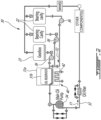
Fig. 2 is a schematic view of an implementation of an oil distribution system for the aircraft engine ofFig. 1 ; -
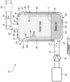
Fig. 3 is a schematic cross-sectional view of a system container of the oil distribution system ofFig. 2 ; -
Fig. 4 is a schematic cross-sectional view of the system container of the oil distribution system ofFig. 3 , with a deaerator located in an oil reservoir; -
Fig. 5 is a schematic cross-sectional view of another implementation of the system container of the oil distribution system ofFig. 2 ; and -
Fig 6 is a schematic cross-sectional view of yet another implementation of the system container of the oil distribution system ofFig. 2 . -
Fig. 1 illustrates an aircraft engine depicted as agas turbine engine 10 of a type preferably provided for use in subsonic flight, generally comprising in serial flow communication aninlet 12 for receiving air, acompressor section 13 for compressing the air received via theinlet 12, acombustor 14 for mixing fuel with the compressed air and for generating an annular stream of combustion gases. Aturbine section 15 receiving the combustion gases from thecombustor 14. Theturbine section 15 has a high-pressure turbine 15A drivingly engaged to thecompressor section 13 via a high-pressure shaft 16. Theturbine section 15 further has a power or low-pressure turbine 15B downstream of the high-pressure turbine 15A and drivingly engaged to aload 17, which may be a propeller, a helicopter rotor, and so on, via a low-pressure shaft 18. The low-pressure shaft 18 may be directly engaged to the load or, as shown herein, drivingly engaged to theload 17 via a reduction gearbox RGB. Thegas turbine engine 10 has anexhaust 19 for expelling the combustion gases. Although the depictedgas turbine engine 10 is a turboprop or turboshaft engine, the present invention may apply to other engines, such as auxiliary power units (APU), turbofans, internal combustion engines or fuel cell units. In an alternate embodiment, the compressor section may include a high-pressure compressor drivingly engaged to the high-pressure turbine 15A via the high-pressure shaft 16 and a low-pressure compressor drivingly engaged to the low-pressure turbine 15B via the low-pressure shaft 18. In the embodiment shown, theload 17 is drivingly engaged to the low-pressure shaft 18 via aclutch 20 that has engaged and disengaged configurations to selectively disengage theload 17 from the low-pressure shaft 18. In the case of a turboshaft application, thisclutch 20 may allow the disengagement of a helicopter rotor from the low-pressure shaft 18. In some applications, such as a turboprop, theclutch 20 may be omitted. - The low-
pressure shaft 18 and the high-pressure shaft 16 are rollingly supported bybearings 21. Typically, thebearings 21 are contained within bearing cavities 22 (Fig. 2 ) that may be hydraulically connected to an oil source to receive oil for lubrication. Anoil distribution system 30 is provided for circulating oil to thebearings 21 and back to anoil reservoir 31b. The oil flowing through theoil distribution system 30 is expected to see its temperature increase during use. It may therefore be required to cool down the oil. - Referring to
Fig. 2 , theoil distribution system 30 is shown in greater detail. Although depicted here in as part of thegas turbine engine 10 ofFig. 1 , theoil distribution system 30 could be used in different powerplants, and more particularly in different thermal engines, such as, and not limited to, internal combustion engine and fuel cell units. Theoil distribution system 30 includes asystem container 31a, anoil circuit 32, which typically includes one or more lines to flow the oil, anoil pump 34 that drives an oil flow F1 within an oil conduit of theoil circuit 32 from theoil reservoir 31b. Theoil distribution system 30 may be a pressure regulated system in which a pressure regulating valve may be connected in parallel to theoil pump 34. The oil exchanges heat atheat exchanger 40 with a cooling fluid 42 (at F2). The oil flow is then distributed between different components in need of oil. These components may include, for instance, one or more bearing cavity(ies) 22, a generator, an actuator, and/or agearbox 23, which may correspond to the reduction gearbox ofFig. 1 or any other gearbox of the engine, in some embodiments. Used oil is then scavenged and scavengepumps 36 drive a scavenge oil flow F2 from scavenge outlets of thebearing cavities 22 and thegearbox 23 back to theoil reservoir 31b where the oil may be flown back to theoil pump 34. Typically, theoil reservoir 31b has a volume devoid of oil (e.g, empty space containing a mist of air and oil). During lubrication, the oil is expected to be mixed with air. Thus, the scavenge oil flow F2 is a multi-phase fluid containing oil and air. The oil may rest some time in the oil tank before being drawn by thepump 34. During this time, the air contained in the oil may naturally separate. A de-oiler and/or de-aerator, such asdeaerator 38 about to be described with reference toFig. 4 , may be used to accelerate the removal of air from the scavenge oil flow F2. It will be appreciated that many other configurations of theoil distribution system 30 are contemplated. For instance, a different number of scavenge pumps may be used, some components may be omitted, and so on. An actuator may be fluidly connected to the oil conduit and may rely on oil pressure for its operation. - Turning now to
Fig. 3 , a portion of theoil distribution system 30 is schematically shown, and includes thesystem container 31a, theoil reservoir 31b and theheat exchanger 40. Thesystem container 31a has, when positioned for use, atop wall 50a, abottom wall 52a and asidewall 54a. In embodiments where thesystem container 31a is not cylindrical, thesystem container 31a has a plurality ofsidewalls 54a. Thetop wall 50a, thebottom wall 52a and thesidewall 54a enclose an internal volume of thesystem container 31a. - The
heat exchanger 40 is disposed in the internal volume of thesystem container 31a. Theheat exchanger 40 has a coolingfluid inlet 56 defined in thesidewall 54a to receive relatively cool cooling fluid 42 into thesystem container 31a. The coolingfluid inlet 56 is located closer to thebottom wall 52a than thetop wall 50a. The coolingfluid inlet 56 is also located below a minimum level L of liquid oil in theoil reservoir 31b for operation of theoil distribution system 30. The coolingfluid inlet 56 could be located above the minimum level L of liquid oil in other implementations, so as to reduce cooling of liquid oil in theoil reservoir 31b as the coolingfluid 42 flows. - The cooling
fluid 42 is drawn by apump 44 from a coolingfluid reservoir 46, and flows in a coolingfluid passage 48 of theheat exchanger 40. The coolingfluid 42 is selected from the group including liquid ammonia, liquid methane, liquid propane, liquid butane, supercritical carbon dioxide, and liquid hydrogen. Suchnon-traditional cooling fluids 42 are adapted for use in aturboexpander 49 that is part of theaircraft engine 10 and schematically shown inFig. 3 . Thenon-traditional cooling fluids 42 have a relatively higher thermal capacity compared to other cooling fluids, such as gasoline, jet fuel, water or ethylene glycol. It is contemplated that other cooling fluids than the ones listed above could be used in theoil distribution system 30. A coolingfluid manifold 58 is connected to thetop wall 50a of thesystem container 31a and is fluidly connected to a coolingfluid outlet 60 of theheat exchanger 40. The coolingfluid manifold 58 and the coolingfluid outlet 60 collect the coolingfluid 42 that has been warmed during its flow through theheat exchanger 40 and allow the warmed coolingfluid 42 to exit thesystem container 31a. - The
oil reservoir 31b is disposed in thesystem container 31a and defines an oil-receiving cavity therein adapted for storing liquid oil and a mist of air and oil. Theoil reservoir 31b has, when positioned for use, atop wall 50b, abottom wall 52b and asidewall 54b. In embodiments where theoil reservoir 31b is not cylindrical, theoil reservoir 31b has a plurality ofsidewalls 54b. The coolingfluid passage 48 is defined between thetop walls bottom walls sidewalls fluid 42 flows in the coolingfluid passage 48, the coolingfluid 42 surrounds theoil reservoir 31b. The coolingfluid 42 surrounding theoil reservoir 31b increases the surface area for heat transfer between the oil present in theoil reservoir 31b and the coolingfluid 42 flowing in the coolingfluid passage 48. Anoil manifold 62 is defined in thesidewall 54b and allows the hot oil flowing from F2 to enter theoil reservoir 31b. Theoil manifold 62 is located closer to thetop wall 50b of theoil reservoir 31b than thebottom wall 52b of theoil reservoir 31b. Theoil manifold 62 allows hot oil to flow downwardly into theoil reservoir 31b. A plurality offins 64 protrude from an inner surface of thesidewall 54b and extend inwardly into the oil-receiving cavity of theoil reservoir 31b. Eachfin 64 of the plurality offins 64 is scooped-shaped and configured for permitting the oil from dripping from an upper fin to a lower fin (i.e. located below the upper fin). Put differently, as the hot oil enters theoil reservoir 31b via theoil manifold 62, the hot oil flows on the plurality offins 64 in a cascading motion, downwardly over the plurality offins 64 until reaching the level L of liquid oil in theoil reservoir 31b, as depicted byarrows 65 inFig. 3 . Having the oil dripping from upper to lower fins increases the travel time of the hot oil between theoil manifold 62 and the bottom of theoil reservoir 31b, which may increase the amount of heat transferred from the oil to the coolingfluid 42. The plurality offins 64 could be shaped otherwise in other implementations, and could be flat for instance. The plurality offins 64 could also extend from an inner-surface of thetop wall 50b and/or of thebottom wall 52b. - The
heat exchanger 40 further includes amatrix 66 disposed in the coolingfluid passage 48. Thematrix 66 is located between the sidewalls 54a, 54b. Thematrix 66 is connected to thesidewalls fins 64. In other implementations, thematrix 66 is connected to at least one of thesidewall 54a,sidewall 54b, and the plurality offins 64. Regardless of how thematrix 66 is connected to at least one of thesidewall 54a,sidewall 54b, and the plurality offins 64, thematrix 66 is in a heat transfer relationship with the plurality offins 64, whether via conductive heat transfer, convective heat transfer, radiation heat transfer or a combination thereof. In some implementation, thesystem container 31a, theoil reservoir 31b and thematrix 66 are integrally formed by, for example, additive manufacturing techniques. Having the plurality offins 64 connected to thematrix 66 of theheat exchanger 40 permit transfer of heat from the oil dripping from onefin 64 to another to thematrix 66 by thermal conduction. Thematrix 66 can have different shapes and topologies in different implementations. Thematrix 66 is shaped and configured to optimize heat transfer between the hot oil flowing on thesidewall 54b and thefins 64 and the coolingfluid 42 flowing in the coolingfluid passage 48. Thematrix 66 includes one or a combination of structures such as microchannels, a lattice structure, and gyroid structures, each having relatively high surface area per volume of thematrix 66, hence increasing heat transfer capabilities of theheat exchanger 40. Thematrix 66 is schematically represented in the Figures, and may differ in scale/shape in different embodiments. As depicted byarrows 70 inFig. 3 , the coolingfluid 42 flows in a direction opposite the flow of oil in theoil reservoir 31b, that is upwardly from the coolingfluid inlet 56, through the coolingfluid passage 48 and thematrix 66, and on to the coolingfluid manifold 58 and the coolingfluid outlet 60. The coolingfluid 42 and oil are thus flowing in opposite directions in theoil distribution system 30, which may further increase the heat transfer therebetween. - In operation, hot oil flowing from the
oil manifold 62 enters theoil reservoir 31b and drips from anupper fin 64 to a lower fin 64 (as depicted by arrows 65) and along thesidewall 54b of theoil reservoir 31b until reaching the liquid oil at the bottom of theoil reservoir 31b. As the oil flows downwardly, the oil is cooled upon contacting thefins 64 and thesidewall 54b being cooled by the coolingfluid 42 pumped bypump 44 and flowing upwardly in the coolingfluid passage 48 and through thematrix 66. The coolingfluid 42 flows between thebottom walls oil reservoir 31b. The warmed coolingfluid 42 flows upwardly between the coolingfluid inlet 56 and the coolingfluid outlet 60, as depicted byarrows 70. - Having the oil cooled while being stored in the
oil reservoir 31b may eliminate the need for a separate heat exchanger located remotely from theoil reservoir 31b, for example an air-cooled oil cooler (ACOC), which may reduce the bulk and weight of theoil distribution system 30 compared to other oil distribution systems. In addition, the use of a coolingfluid 42 with relatively high thermal capacity such as the ones described above may provide for adequate heat transfer while using a reduced volume of cooling fluid compared to other cooling fluids, such as water, fuel or ethylene glycol. This may in turn reduce the bulk and weight of theoil distribution system 30 while offering similar or better heat transfer. - Turning now to
Fig. 4 , anoil distribution system 130 is shown. For simplicity, theoil distribution system 130 has same or similar features and structures as theoil distribution system 30, and these features and structures are identified with the same reference numeral, for simplicity. Theoil distribution system 130 further includes thedeaerator 38 located in an upper portion of theoil reservoir 31b. Put differently, the deaerator is located closer to thetop wall 50b of theoil reservoir 31b than thebottom wall 52b. Thedeaerator 38 separates air from oil upon entry of the hot oil via theoil manifold 62 in the oil-receiving cavity of theoil reservoir 31b, and thedeaerator 38 feeds hot deaerated oil into theoil reservoir 31b. More particularly, thedeaerator 38 rotates and spills hot deaerated oil on a larger portion of thesidewall 54b and onseveral fins 64 upon rotation thereof. Since the hot deaerated oil is projected on a larger portion of thesidewall 54b and onseveral fins 64 simultaneously, heat transfer between the oil and the coolingfluid 42 is increased as the hot oil is in contact with more surface area of thesidewall 54b andfins 64. The deaerated oil then flows from anupper fin 64 to alower fin 64 and on thesidewall 54b in a cascading motion, as depicted byarrows 65, until reaching the liquid oil at the bottom of theoil reservoir 31b. It is also contemplated that thedeaerator 38 could be static in other implementations. - Referring now to
Fig. 5 , anoil distribution system 230 is shown. For simplicity, theoil distribution system 230 has same or similar features and structures as theoil distribution system 30, and these features and structures are identified with the same reference numeral, for simplicity. Theheat exchanger 40 disposed in thesystem container 31a has anintermediate wall 54c located between thetop wall 50a of thesystem container 31a and the top wall of theoil reservoir 31b, between thebottom wall 52a of thesystem container 31a and thebottom wall 52b of theoil reservoir 31b, and between thesidewall 54a of thesystem container 31a and thesidewall 54b of theoil reservoir 31b. Anoil inlet 62a is defined in theintermediate wall 54c and allows hot oil to flow in anoil passage 62b located between thesidewall 54b and theintermediate wall 54c. Anoil outlet 62c is defined in theoil reservoir 31b, and is fluidly connected to theoil passage 62b. The coolingfluid inlet 56 is defined in thesidewall 54a of thesystem container 31a, and is fluidly connected to the coolingfluid passage 48 located betweenintermediate wall 54c and thesidewall 54a. Thematrix 66 is disposed between theintermediate wall 54c and thesidewall 54a. Thematrix 66 is connected or integrally formed with theintermediate wall 54c and/or thesidewall 54a, in order to allow heat transfer using thermal conductivity. - In operation, hot oil flows upwardly in the
oil passage 62b between theoil inlet 62a and theoil outlet 62c, as depicted byarrows 265. As hot oil flows in theoil passage 62b, the oil contacts theintermediate wall 54c being cooled by thematrix 66 and the coolingfluid 42 flowing between the coolingfluid inlet 56 and the coolingfluid outlet 60. It is noted in this implementation that both the oil and the coolingfluid 42 flow upwardly, as depicted byarrows oil inlet 62a, the cooled oil enters theoil reservoir 31b. Although not depicted in the Figs., theoil reservoir 31b could include a plurality offins 64 extending therein for increased heat transfer. - Referring now to
Fig. 6 , anotheroil distribution system 330 is shown. For simplicity, theoil distribution system 330 has same or similar features and structures as theoil distribution system 230, and these features and structures are identified with the same reference numeral, for simplicity. In the implementation shown, theoil passage 62b is located between thesidewall 54a and theintermediate wall 54c, and the coolingfluid passage 48 is located between thesidewall 54b and theintermediate wall 54c. Theoil inlet 62a is defined in thebottom wall 52a and theoil outlet 62c is defined in thetop wall 50b of theoil reservoir 31b. The coolingfluid inlet 56 is defined in theintermediate wall 54c, and is fluidly connected to the coolingfluid passage 48 located betweenintermediate wall 54c and thesidewall 54b. Thematrix 66 is connected to or formed integrally with theintermediate wall 54c. Thematrix 66 extends laterally between the sidewalls 54a, 54b. Put differently, thematrix 66 extends in both the coolingfluid passage 48 and in theoil passage 62b. - In operation, hot oil flows upwardly in the
oil passage 62b between theoil inlet 62a and theoil outlet 62c, as depicted byarrows 365. As hot oil flows in theoil passage 62b, the oil contacts theintermediate wall 54c and thematrix 66. The coolingfluid 42 also flows upwardly in the coolingfluid passage 48 and contacts thematrix 66. It is noted in this implementation that both the oil and the coolingfluid 42 flow upwardly along thesidewalls respective passages arrows fluid 42 upon contact thereof with theintermediate wall 54c and thematrix 66. When the cooled oil has reached theoil outlet 62c, the cooled oil enters theoil reservoir 31b. - The embodiments described in this document provide non-limiting examples of possible implementations of the present technology. Upon review of the present invention, a person of ordinary skill in the art will recognize that changes may be made to the embodiments described herein without departing from the scope of the present technology. For example, the direction of flow of the oil and cooling fluid could vary in other implementations. Yet further modifications could be implemented by a person of ordinary skill in the art in view of the present invention, which modifications would be within the scope of the present technology.
Claims (13)
- An aircraft engine oil distribution system (30) comprising:a system container (31a) having one or more walls (50a, 52a, 54a) enclosing an internal volume;an oil reservoir (31b) disposed in the internal volume of the system container (31a) and defining an oil-receiving cavity therein for storing liquid oil and a mist of air and oil, the oil reservoir (31b) having a plurality of fins (64) protruding from an inner surface of a wall (50b, 52b, 54b) of the oil reservoir (31b) and extending into the oil-receiving cavity; anda heat exchanger (40) disposed in the internal volume of the system container (31a), the heat exchanger (40) including:a cooling fluid passage (48) extending between a cooling fluid inlet (56) and a cooling fluid outlet (60), the cooling fluid passage (48) defined between the one or more walls (50a, 52a, 54a) of the system container (31a) and the wall (50b, 52b, 54b) of the oil reservoir (31b) and permitting flow of a cooling fluid (42) therein; anda matrix (66) disposed in the cooling fluid passage (48) in heat transfer relationship with the plurality of fins (64) of the oil reservoir (31b).
- The aircraft engine oil distribution system (30) of claim 1, wherein the cooling fluid passage (48) is defined between a bottom wall (52a) of the system container (31a) and a bottom wall (52b) of the oil reservoir (31b), between a sidewall (54a) of the system container (31a) and the wall (54b) of the oil reservoir (31b), and between a top wall (50a) of the system container (31a) and a top wall (50b) of the oil reservoir (31b).
- The aircraft engine (10) oil distribution system (30) of claim 2, wherein the cooling fluid inlet (56) is located closer to the bottom wall (52a) of the system container (31a) than the top wall (50a) of the system container (31a), and the cooling fluid (42) flows upwardly in the cooling fluid passage (48).
- The aircraft engine oil distribution system (30) of any preceding claim, further comprising an oil manifold (62) located above the plurality of fins (64) and allowing hot oil to cascade downwardly over the plurality of fins (64).
- The aircraft engine oil distribution system (30) of claim 4, wherein the cooling fluid (42) flows through the cooling fluid passage (48) in a direction opposite a flow of oil over the plurality of fins (64) within the oil reservoir (31b).
- The aircraft engine oil distribution system (30) of any preceding claim, wherein the plurality of fins (64) is connected to the matrix (66) of the heat exchanger (40) for transferring heat from the oil located in the oil reservoir (31b) to the matrix (66) by thermal conduction.
- The aircraft engine oil distribution system (30) of any preceding claim, wherein the plurality of fins (64) are scoop-shaped and configured for permitting the oil to drip from a first fin (64) to a second fin (64) located below the first fin (64).
- The aircraft engine oil distribution system (30) of any preceding claim, wherein the matrix (66) includes at least one of microchannels, a lattice structure, and gyroid structures.
- The aircraft engine oil distribution system (30) of any preceding claim, further comprising a deaerator (38) for separating air from oil upon entry in the oil reservoir (31b) and feeding hot deaerated oil into the oil reservoir (31b).
- The aircraft engine oil distribution system (30) of claim 9, wherein the deaerator (38) is rotatable and is configured to spill hot deaerated oil on the wall (50b, 52b, 54b) of the oil reservoir (31b) and the plurality of fins (64) upon rotation thereof.
- The aircraft engine oil distribution system (30) of any preceding claim, wherein the cooling fluid (42) is selected from a group comprising liquid ammonia, liquid methane, liquid propane, liquid butane, supercritical carbon dioxide, and liquid hydrogen.
- The aircraft engine oil distribution system (30) of any preceding claim, wherein the cooling fluid (42) is configured for use in a turboexpander (49).
- The aircraft engine oil distribution system (30) of any preceding claim, wherein the heat exchanger (40) includes:an intermediate wall (54c) extending between the wall of the oil reservoir (31b) and the one or more walls (50a, 52a, 54a) of the system container (31a); andan oil passage (62b) fluidly connected between an oil inlet (62a) and an oil outlet (62c), the oil passage (62b) defined between one of the one or more walls (50a, 52a, 54a) of the system container (31a) and the wall (50b, 52b, 54b) of the oil reservoir (31b), and the intermediate wall (54c), wherein:the cooling fluid passage (48) is defined between another one of the one or more walls (50a, 52a, 54a) of the system container (31a) and the wall (50b, 52b, 54b) of the oil reservoir (31b), and the intermediate wall (54c); andthe matrix (66) disposed in the cooling fluid passage (48) being in heat transfer relationship with the intermediate wall (54c).
Applications Claiming Priority (1)
| Application Number | Priority Date | Filing Date | Title |
|---|---|---|---|
| US18/207,252 US12448919B2 (en) | 2023-06-08 | 2023-06-08 | Aircraft engine oil distribution system |
Publications (1)
| Publication Number | Publication Date |
|---|---|
| EP4474622A1 true EP4474622A1 (en) | 2024-12-11 |
Family
ID=91469908
Family Applications (1)
| Application Number | Title | Priority Date | Filing Date |
|---|---|---|---|
| EP24181099.3A Pending EP4474622A1 (en) | 2023-06-08 | 2024-06-10 | Aircraft engine oil distribution system |
Country Status (3)
| Country | Link |
|---|---|
| US (1) | US12448919B2 (en) |
| EP (1) | EP4474622A1 (en) |
| CA (1) | CA3232847A1 (en) |
Citations (6)
| Publication number | Priority date | Publication date | Assignee | Title |
|---|---|---|---|---|
| DE112008001778T5 (en) * | 2007-07-03 | 2010-08-26 | Toyota Boshoku Kabushiki Kaisha, Kariya-shi | Oil Tanker |
| US20190338705A1 (en) * | 2018-05-03 | 2019-11-07 | Rolls-Royce Plc | Oil Tank |
| US20200271014A1 (en) * | 2019-02-21 | 2020-08-27 | Rolls-Royce Corporation | Multi-Function Oil Tank |
| US20200284165A1 (en) * | 2019-03-08 | 2020-09-10 | Rolls-Royce Corporation | Self-Cooling Oil Tank |
| US11525399B1 (en) * | 2021-06-17 | 2022-12-13 | Pratt & Whitney Canada Corp. | Oil system with flow restrictor |
| EP4372213A1 (en) * | 2022-11-14 | 2024-05-22 | Pratt & Whitney Canada Corp. | Lubricant reservoir with integrated heat exchanger |
Family Cites Families (9)
| Publication number | Priority date | Publication date | Assignee | Title |
|---|---|---|---|---|
| US810844A (en) * | 1904-12-13 | 1906-01-23 | John F Wagner | Lubricator. |
| US2450960A (en) * | 1945-09-12 | 1948-10-12 | Jack & Heintz Prec Ind Inc | Oil tank and cooler assembly |
| US2944966A (en) * | 1954-02-19 | 1960-07-12 | Allen G Eickmeyer | Method for separation of fluid mixtures |
| FR2798983B1 (en) * | 1999-09-10 | 2001-11-23 | Eurocopter France | LUBRICATION DEVICE OF A MULTIPLIER-REDUCER MECHANICAL ASSEMBLY |
| US7637337B2 (en) * | 2007-04-19 | 2009-12-29 | Ford Global Technologies, Llc | Transmission oil pan |
| US10578020B2 (en) | 2015-07-21 | 2020-03-03 | Unison Industries, Llc | Integral oil tank heat exchanger |
| JP7245709B2 (en) * | 2019-04-26 | 2023-03-24 | 三菱重工コンプレッサ株式会社 | Lubricant tanks and rotating machinery systems |
| US11629637B2 (en) * | 2020-11-18 | 2023-04-18 | Hamilton Sundstrand Corporation | Supercritical carbon dioxide-cooled generator and turbine |
| WO2022226480A1 (en) * | 2021-04-18 | 2022-10-27 | Plug Power Inc. | Heat exchanging channel forming an internal cavity that stores cryogenic material |
-
2023
- 2023-06-08 US US18/207,252 patent/US12448919B2/en active Active
-
2024
- 2024-03-21 CA CA3232847A patent/CA3232847A1/en active Pending
- 2024-06-10 EP EP24181099.3A patent/EP4474622A1/en active Pending
Patent Citations (6)
| Publication number | Priority date | Publication date | Assignee | Title |
|---|---|---|---|---|
| DE112008001778T5 (en) * | 2007-07-03 | 2010-08-26 | Toyota Boshoku Kabushiki Kaisha, Kariya-shi | Oil Tanker |
| US20190338705A1 (en) * | 2018-05-03 | 2019-11-07 | Rolls-Royce Plc | Oil Tank |
| US20200271014A1 (en) * | 2019-02-21 | 2020-08-27 | Rolls-Royce Corporation | Multi-Function Oil Tank |
| US20200284165A1 (en) * | 2019-03-08 | 2020-09-10 | Rolls-Royce Corporation | Self-Cooling Oil Tank |
| US11525399B1 (en) * | 2021-06-17 | 2022-12-13 | Pratt & Whitney Canada Corp. | Oil system with flow restrictor |
| EP4372213A1 (en) * | 2022-11-14 | 2024-05-22 | Pratt & Whitney Canada Corp. | Lubricant reservoir with integrated heat exchanger |
Also Published As
| Publication number | Publication date |
|---|---|
| US20240410318A1 (en) | 2024-12-12 |
| CA3232847A1 (en) | 2025-06-13 |
| US12448919B2 (en) | 2025-10-21 |
Similar Documents
| Publication | Publication Date | Title |
|---|---|---|
| US11939078B1 (en) | Active fuel thermal conditioning for aircraft | |
| US11560239B2 (en) | Regenerative thermal management system | |
| US8601785B2 (en) | Oil supply system with main pump deaeration | |
| EP0248762B1 (en) | Fuel and oil heat management system for a gas turbine engine | |
| US8266889B2 (en) | Gas turbine engine fan bleed heat exchanger system | |
| US8893856B2 (en) | Gravity scavenged generator with integral engine oil tank | |
| US8752673B2 (en) | Lubrication system with porous element | |
| EP3786428B1 (en) | Oil tank for geared turbofan engine | |
| RU2625391C1 (en) | Gas turbine, containing primary and secondary coolers of lube oil | |
| US12157578B2 (en) | Aircraft power plant | |
| US20140150439A1 (en) | Lubrication System for Gas Turbine Engines | |
| US20190195129A1 (en) | Fuel lubricated foil bearing | |
| US12345201B2 (en) | Gearbox assembly with lubricant extraction volume ratio | |
| CN116733607A (en) | Combination gas turbine engine and power electronics | |
| CN118223986A (en) | Gas turbine engine | |
| EP4372213A1 (en) | Lubricant reservoir with integrated heat exchanger | |
| US12448919B2 (en) | Aircraft engine oil distribution system | |
| US20220316361A1 (en) | Oil tank for aircraft engine | |
| US11791480B2 (en) | Aircraft with a fuel cell and a structure having a tank containing a heat-transfer fluid ensuring the cooling of the fuel cell | |
| EP4438863B1 (en) | Lubrication system with pump feed from de-aerator | |
| US12172769B2 (en) | System and method for cooling a fluid of a lubrication or cooling circuit of a drive unit of an aircraft, and aircraft propulsion engine provided with such a cooling system | |
| CN115342665A (en) | Thermal management system | |
| US11927135B2 (en) | Integrated oil tank with passive thermal modulation | |
| US20250382896A1 (en) | Hydraulically driven de-oiler for gas turbine engines | |
| US20260138745A1 (en) | System for pre-cooling air supplied to an aircraft environmental control system |
Legal Events
| Date | Code | Title | Description |
|---|---|---|---|
| PUAI | Public reference made under article 153(3) epc to a published international application that has entered the european phase |
Free format text: ORIGINAL CODE: 0009012 |
|
| STAA | Information on the status of an ep patent application or granted ep patent |
Free format text: STATUS: THE APPLICATION HAS BEEN PUBLISHED |
|
| AK | Designated contracting states |
Kind code of ref document: A1 Designated state(s): AL AT BE BG CH CY CZ DE DK EE ES FI FR GB GR HR HU IE IS IT LI LT LU LV MC ME MK MT NL NO PL PT RO RS SE SI SK SM TR |
|
| STAA | Information on the status of an ep patent application or granted ep patent |
Free format text: STATUS: REQUEST FOR EXAMINATION WAS MADE |
|
| 17P | Request for examination filed |
Effective date: 20250611 |