EP4474571A2 - Frame for a fabric insertion unit in a fiber web machine and fabric insertion unit for a fiber web machine - Google Patents
Frame for a fabric insertion unit in a fiber web machine and fabric insertion unit for a fiber web machine Download PDFInfo
- Publication number
- EP4474571A2 EP4474571A2 EP24177575.8A EP24177575A EP4474571A2 EP 4474571 A2 EP4474571 A2 EP 4474571A2 EP 24177575 A EP24177575 A EP 24177575A EP 4474571 A2 EP4474571 A2 EP 4474571A2
- Authority
- EP
- European Patent Office
- Prior art keywords
- frame
- frame according
- fiber web
- channels
- fabric
- Prior art date
- Legal status (The legal status is an assumption and is not a legal conclusion. Google has not performed a legal analysis and makes no representation as to the accuracy of the status listed.)
- Pending
Links
Images

Classifications
-
- D—TEXTILES; PAPER
- D21—PAPER-MAKING; PRODUCTION OF CELLULOSE
- D21F—PAPER-MAKING MACHINES; METHODS OF PRODUCING PAPER THEREON
- D21F7/00—Other details of machines for making continuous webs of paper
- D21F7/001—Wire-changing arrangements
Definitions
- Chinese patent application number CN108221451 discloses a fabric insertion unit, which is a device for changing a fabric in a fiber web machine.
- the fabric insertion unit includes two oppositely arranged transfer devices including lifting means.
- the transfer device has a frame having internal channels for fluid equipped in the lifting means.
- the channels are formed of several bores from several directions. Also puncture holes are needed.
- puncture holes are needed.
- several orifices are used. Each orifice is installed deep in the channel.
- the orifices need special and accurate bores.
- the casting may include pores, which may lead to leakages and pressure losses.
- other machining of the cast frame is hard and time consuming due the said pores and carbides. If any of bores become damaged or the frame somehow get hurt, the whole frame has to be changed.
- the object of the invention is to provide a new frame for a fabric insertion unit in a fiber web machine, which frame is more durable than before, and also easier and quicker to manufacture and maintain.
- the characteristic features of the frame according to the invention are stated in the accompanying Claim 1. With new constructions, less bores are needed, and they are easier to drill than before. Also, the installation of the orifices is easy, and the orifices are quick to maintain.
- Another object of the invention is to provide a new fabric insertion unit in a fiber web machine which is more reliable and easier to maintain than before.
- the characteristic features of the fabric insertion unit according to the invention are stated in the accompanying Claim 14. The leakages of fluid and pressure may be avoided, and the functions of the fabric insertion unit can be easily amended, if needed.
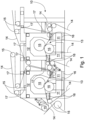
- Figure 1 shows an example of the press section of a fiber web machine, viewed from the tending side.
- the press section includes a framework 10, which has several beam structures 11 and 12. The load is supported especially by the vertical beams, which can also be slanted.
- the press section has two presses 13, each of which has two fabrics 14.
- the fabrics 14 formed into endless loops are supported by rolls 15. The rolls are supported on the framework 10. From time to time, each fabric must be replaced.
- Fiber web machine refers to, for example, paper, cardboard and pulp machines and belt calenders with replaceable fabrics. Closed fabric loops include, for example, the wires on the web forming part and the felts and belts on the press section of the fiber web machine.
- fabric insertion units 16 are arranged in the framework 10 on the tending side.
- the fabric insertion units will later be referred to more simply as units.
- the unit is used to change the fabric on a web forming machine and the unit is intended to be installed in the frame 10 of the web forming machine.
- Figure 1 shows the units 16 in principle.
- the framework 10 includes spacers 17, which are removed when changing the fabric 14.
- FIG 2a shows the unit 16 according to the invention detached from the framework of the fiber web machine.
- the unit 16 includes two oppositely arranged transfer devices 18 for moving the fabric 14.
- the unit includes lifting means 19 for forming a transfer passage between the transfer devices 18 for the fabric 14.
- the transfer passage enables the fabric to be taken through the framework of the fiber web machine.
- each transfer device 18 includes a frame 20 adapted as a part of the lifting means.
- each frame is attached to the fiber web machine with plurality of bolts 21.
- the lifting means function by pressurized fluid.
- the frame 20 has internal channels 22 for fluid equipped in the lifting means 19, as shown in Figure 2b .
- one or more of the channels 22 is equipped with an orifice 23 ( Figure 3b ) in order to control the flow of fluid.
- the locking means 24 are loosened. Then, the distance between the transfer devices, more specifically the frames of the transfer device, is increased by using the lifting means. In practice, a sufficient lift is 0,5 - 10 mm. In this case, the frames are separated from each other, so that the intermediate structure 25 can be removed. Thus, the transfer passage is formed between the frames, making it possible to transfer the fabric using transfer devices.
- the lifting means is arranged as part of the frame of the transfer device. More specifically, the lifting means includes a pressure chamber delimited by a pressure water seal in the frame. The seal has rounded rectangular perimeter, and it delimits the pressure chamber together with a metal belt loop supported by the turning rolls. The turning rolls are attached to the frame and there is a drive in one or more turning rolls.
- fluid for example water
- Both frames have the same kind of channels, and the lifting means function equally, as shown in Figure 2a .
- Figure 2b is shown three channels 22 for pressurized water at the upper frame 20 and one channel 22 for leakage water at the lower frame 20.
- the first channel ends to the pressure chamber and the second channel ends to a slot 26 for the seal.
- the pressurized water pushes the seal against the metal belt loop.
- the third channel ends to another slot 27 for leakage water seal.
- the fourth channel is situated between the abovementioned slots 26 and 27. A part of the fluid leaks and it flows out from the frame.
- both frames include four channels mentioned above.
- each frame 20 has an external block 28 including the orifice 23 and a part of the channel 22.
- the bores to the frame may be simple and without any threads.
- the channels can be optimized without thinking the threads and bores.
- the block itself is small, and it is easy to machine.
- the material of the block can be selected freely.
- the block is attached to the frame by four bolts 21.
- the block 28 is detachable fixed to the frame 20. When the block is detached, it is easy the change each orifice if necessary.
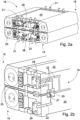
- Figure 3b shows a cross section of the block 28.
- the block 28 is arranged as a manifold including one main channel 29 for several channels 22.
- the block 28 includes one inlet 30 and one outlet 31.
- the inlet 30 is without a coupling for the pressurized fluid.
- the flow of fluid in each channel can be controlled independently.
- Basic structure of the orifices is the same, only the diameter of the center hole 32 varies. The bigger hole, the bigger flow.
- the surface of the frame 20 can be flat at the area of the channels. This makes the machining of the frame easier. Then there is a seal 34 between the block 28 and the frame 20 for each channel 22.
- the seal is an O-ring seal.
- the seal may be a standard seal and each channel is securely sealed.
- the frame 20 consists of two plate pieces 35 arranged on top of each other.
- the plate material is cheap, but has uniform quality and it is easy to machine.
- all the channels 22 are included in one of the plate pieces 35.
- the channels are in the thicker plate piece.
- the slots for the seals of the pressure chamber are in the same plate piece.
- Each plate piece may be machined independently. However, the final machining is done when the plate pieces are fixed to each other.
- the frame may consist of one, two or more plate pieces.
- the frame of two plate pieces is shown as an advantageous embodiment.
- the plate piece 35 is of stainless or acid proof steel. Steel is easy to machine, and the material is firm and corrosion resistant. Also, one or more of the channels may consist of grooves machined on the surfaces of the plate pieces. Thus, even less borings are needed. Also aluminum is a possible material like iron with suitable coating against corrosion. In addition, the plate piece may be a 3D-printed piece. Also composites with fiber reinforcements may be used.
- the plate pieces 35 are bolted together with ten bolts.
- the joint between the plate pieces is depicted with a dashed line in Figure 3a .
- other fixing methods may be used, for example, welding, interference fitting, riveting, or gluing.
- the friction between the plate pieces is increased with one or more ways like, for example by using chemicals or coatings in one or more metal pieces.
- the surfaces may by machined to increase the roughness or even for forming form fittings.
- friction shims or like may be used and the plate pieces may be manufactured from different materials in the first place. With the increased friction or other structures, the sliding between the plate pieces can be diminished or even prevented. In this way, the plate pieces will not flex as much. Thus, smaller, or fewer bolts are needed.
- Figure 3b shows two keys 36 arrange in the joint between the plate pieces prevention the sliding between the plate pieces. More generally, between the plate pieces 35 there is one or more keys 36. Advantageously, one or more of the keys 36 is orientated parallel to the interface between the plate pieces 35. Thus, the strength of the key can be utilized. Interchangeably to the shown rectangular keys in sideway, one or more round pins 37 may be used.
Landscapes
- Paper (AREA)
- Treatment Of Fiber Materials (AREA)
- Nonwoven Fabrics (AREA)
Abstract
Description
- The present invention relates to a frame for a fabric insertion unit in a fiber web machine, the frame having internal channels for fluid, and one or more of the channels is equipped with an orifice. The invention relates also to fabric insertion unit for a fiber web machine.
- Chinese patent application number
CN108221451 discloses a fabric insertion unit, which is a device for changing a fabric in a fiber web machine. The fabric insertion unit includes two oppositely arranged transfer devices including lifting means. The transfer device has a frame having internal channels for fluid equipped in the lifting means. The channels are formed of several bores from several directions. Also puncture holes are needed. In order to control the flow of fluid, several orifices are used. Each orifice is installed deep in the channel. - It is laborious to drill the channels to the frame. Especially, the orifices need special and accurate bores. In addition, it is hard to install the orifices and there is little space for inlet joints according to prior art. Also, when a cast frame is used, the casting may include pores, which may lead to leakages and pressure losses. Also other machining of the cast frame is hard and time consuming due the said pores and carbides. If any of bores become damaged or the frame somehow get hurt, the whole frame has to be changed. Also, the puncture from a bore to another strains the drill. Due the puncture, metal chips may remain in the channel. The impurities may lead to damages of the seals of the lifting means or clogging of the orifices.
- The object of the invention is to provide a new frame for a fabric insertion unit in a fiber web machine, which frame is more durable than before, and also easier and quicker to manufacture and maintain. The characteristic features of the frame according to the invention are stated in the accompanying Claim 1. With new constructions, less bores are needed, and they are easier to drill than before. Also, the installation of the orifices is easy, and the orifices are quick to maintain. Another object of the invention is to provide a new fabric insertion unit in a fiber web machine which is more reliable and easier to maintain than before. The characteristic features of the fabric insertion unit according to the invention are stated in the accompanying
Claim 14. The leakages of fluid and pressure may be avoided, and the functions of the fabric insertion unit can be easily amended, if needed. - The invention is described below in detail by referring to the enclosed drawings, which illustrate some of the embodiments of the invention, in which
- Figure 1
- shows an example of the body of the press section of a fiber web machine, viewed from the side,
- Figure 2a
- shows a complete fabric insertion unit to be attached to a fiber web machine,
- Figure 2b
- shows a partial cross section of the unit,
- Figure 3a
- shows a frame of a transfer device,
- Figure 3b
- shows a cross section of the block according to the invention with three different orifices.
-
Figure 1 shows an example of the press section of a fiber web machine, viewed from the tending side. The press section includes aframework 10, which hasseveral beam structures presses 13, each of which has twofabrics 14. Thefabrics 14 formed into endless loops are supported byrolls 15. The rolls are supported on theframework 10. From time to time, each fabric must be replaced. Fiber web machine refers to, for example, paper, cardboard and pulp machines and belt calenders with replaceable fabrics. Closed fabric loops include, for example, the wires on the web forming part and the felts and belts on the press section of the fiber web machine. - In the shown embodiment, several
fabric insertion units 16 are arranged in theframework 10 on the tending side. The fabric insertion units will later be referred to more simply as units. The unit is used to change the fabric on a web forming machine and the unit is intended to be installed in theframe 10 of the web forming machine.Figure 1 shows theunits 16 in principle. In addition to theunits 16, theframework 10 includesspacers 17, which are removed when changing thefabric 14. -
Figure 2a shows theunit 16 according to the invention detached from the framework of the fiber web machine. Theunit 16 includes two oppositely arrangedtransfer devices 18 for moving thefabric 14. In addition, the unit includes lifting means 19 for forming a transfer passage between thetransfer devices 18 for thefabric 14. In practice, the transfer passage enables the fabric to be taken through the framework of the fiber web machine. Furthermore, eachtransfer device 18 includes aframe 20 adapted as a part of the lifting means. Also, each frame is attached to the fiber web machine with plurality ofbolts 21. The lifting means function by pressurized fluid. For this, theframe 20 hasinternal channels 22 for fluid equipped in the lifting means 19, as shown inFigure 2b . In addition, one or more of thechannels 22 is equipped with an orifice 23 (Figure 3b ) in order to control the flow of fluid. - In
Figure 2a , theunit 16 is in the production position and thetransfer devices 18 are connected to each other on both edges with locking means 24, which here are eye bolts. The locking means prevent the mutual movement of the frames during production, keeping the frames together despite vibration and load. During the production, anintermediate structure 25 is between the frames, carrying the load from frame to frame. - When changing the fabric, the locking means 24 are loosened. Then, the distance between the transfer devices, more specifically the frames of the transfer device, is increased by using the lifting means. In practice, a sufficient lift is 0,5 - 10 mm. In this case, the frames are separated from each other, so that the
intermediate structure 25 can be removed. Thus, the transfer passage is formed between the frames, making it possible to transfer the fabric using transfer devices. - As mentioned, the lifting means is arranged as part of the frame of the transfer device. More specifically, the lifting means includes a pressure chamber delimited by a pressure water seal in the frame. The seal has rounded rectangular perimeter, and it delimits the pressure chamber together with a metal belt loop supported by the turning rolls. The turning rolls are attached to the frame and there is a drive in one or more turning rolls.
- Advantageously, fluid, for example water, is fed into the pressure chamber, which at the same time lubricates the seals gliding against the metal belt without contaminating the environment. Both frames have the same kind of channels, and the lifting means function equally, as shown in
Figure 2a . However, inFigure 2b is shown threechannels 22 for pressurized water at theupper frame 20 and onechannel 22 for leakage water at thelower frame 20. The first channel ends to the pressure chamber and the second channel ends to aslot 26 for the seal. The pressurized water pushes the seal against the metal belt loop. The third channel ends to anotherslot 27 for leakage water seal. The fourth channel is situated between theabovementioned slots - According to the invention, each
frame 20 has anexternal block 28 including theorifice 23 and a part of thechannel 22. In this way, the bores to the frame may be simple and without any threads. In practice, the channels can be optimized without thinking the threads and bores. Also, the block itself is small, and it is easy to machine. In addition, the material of the block can be selected freely. Here the block is attached to the frame by fourbolts 21. In other words, theblock 28 is detachable fixed to theframe 20. When the block is detached, it is easy the change each orifice if necessary. -
Figure 3b shows a cross section of theblock 28. Advantageously, theblock 28 is arranged as a manifold including onemain channel 29 forseveral channels 22. Thus via asingle inlet 30 fluid can be fed to several channels. In practice, theblock 28 includes oneinlet 30 and oneoutlet 31. InFigure 3b theinlet 30 is without a coupling for the pressurized fluid. Here, there is threedifferent orifices 23. Thus the flow of fluid in each channel can be controlled independently. Basic structure of the orifices is the same, only the diameter of thecenter hole 32 varies. The bigger hole, the bigger flow. Between thechannel 22 and theorifice 23 there is athread 33. Thus the orifice stays in place, and it is easy to release with a standard tool. - As shown on
Figure 3a , the surface of theframe 20 can be flat at the area of the channels. This makes the machining of the frame easier. Then there is aseal 34 between theblock 28 and theframe 20 for eachchannel 22. Here, the seal is an O-ring seal. The seal may be a standard seal and each channel is securely sealed. With the external block according to the invention, the number of cross bores can be reduced when the throttling of the flows is implemented inside the external block forming the manifold. The block significantly reduced machining of the frame and assembly time of the unit. The orifices are now screwed onto the surface of the external manifold. Thus the orifices are easy to install and replace. At the same time, the whole unit is more reliable and easier to maintain and adjust. The same manifold can be used in different sized units. - In addition to the unique block, the structure of the frame is new. Now the
frame 20 consists of twoplate pieces 35 arranged on top of each other. First, the plate material is cheap, but has uniform quality and it is easy to machine. Advantageously, all thechannels 22 are included in one of theplate pieces 35. Here the channels are in the thicker plate piece. Also the slots for the seals of the pressure chamber are in the same plate piece. Each plate piece may be machined independently. However, the final machining is done when the plate pieces are fixed to each other. In principle, the frame may consist of one, two or more plate pieces. Here, the frame of two plate pieces is shown as an advantageous embodiment. - In practice, the
plate piece 35 is of stainless or acid proof steel. Steel is easy to machine, and the material is firm and corrosion resistant. Also, one or more of the channels may consist of grooves machined on the surfaces of the plate pieces. Thus, even less borings are needed. Also aluminum is a possible material like iron with suitable coating against corrosion. In addition, the plate piece may be a 3D-printed piece. Also composites with fiber reinforcements may be used. - In the shown embodiment, the
plate pieces 35 are bolted together with ten bolts. The joint between the plate pieces is depicted with a dashed line inFigure 3a . Also other fixing methods may be used, for example, welding, interference fitting, riveting, or gluing. Also, the friction between the plate pieces is increased with one or more ways like, for example by using chemicals or coatings in one or more metal pieces. Also the surfaces may by machined to increase the roughness or even for forming form fittings. In addition, friction shims or like may be used and the plate pieces may be manufactured from different materials in the first place. With the increased friction or other structures, the sliding between the plate pieces can be diminished or even prevented. In this way, the plate pieces will not flex as much. Thus, smaller, or fewer bolts are needed. -
Figure 3b shows twokeys 36 arrange in the joint between the plate pieces prevention the sliding between the plate pieces. More generally, between theplate pieces 35 there is one ormore keys 36. Advantageously, one or more of thekeys 36 is orientated parallel to the interface between theplate pieces 35. Thus, the strength of the key can be utilized. Interchangeably to the shown rectangular keys in sideway, one or more round pins 37 may be used. - By using plate material there are no pores or fractions inside the frame. Thus, the machining of the frame is quick and easy without drill damages. In addition, casting of the frame would take several months, while the machining of plate material would take only a few weeks. In addition the improved quality, the manufacturing costs will be lower than before.
Claims (15)
- Frame for a fabric insertion unit in a fiber web machine, the frame (20) having internal channels (22) for fluid, and one or more of the channels (22) is equipped with an orifice (23), characterized in that the frame (20) has an external block (28) including the orifice (23) and a part of the channel (22).
- Frame according to claim 1, characterized in that the block (28) is detachable fixed to the frame (20).
- Frame according to claim 1 or 2, characterized in that there is a seal (34) between the block (28) and the frame (20) for each channel (22).
- Frame according to any of claims 1 - 3, characterized in that the block (28) is arranged as a manifold including one main channel (29) for several channels (22).
- Frame according to any of claims 1 - 4, characterized in that between the channel (22) and the orifice (23) there is a thread (33).
- Frame according to any of claims 1 - 5, characterized in that the block (28) includes one inlet (30) and one outlet (31) .
- Frame according to any of claims 1 - 6, characterized in that the frame (19) consists of two or more plate pieces (35) arranged on top of each other.
- Frame according to claim 7, characterized in that all the channels (22) are included in one of the plate pieces (35) .
- Frame according to claim 7 or 8, characterized in that one or more of the channels (22) consist of grooves machined on the surfaces of the plate pieces (35).
- Frame according to any of claims 7 - 9, characterized in that between the plate pieces (35) there is one or more keys (36).
- Frame according to claim 10, characterized in that one or more of the keys (36) is orientated parallel to the interface between the plate pieces (35).
- Frame according to any of claims 7 - 11, characterized in that each plate piece (35) is of stainless or acid proof steel.
- Frame according to any of claims 7 - 12, characterized in that the plate pieces (35) are bolted together.
- Fabric insertion unit for a fiber web machine, which unit (16) is arranged to be installed in a framework (10) of a fiber web machine, and which unit (16) includes two oppositely arranged transfer devices (18) for transferring a fabric (14) and including lifting means (19) for forming a transfer passage (20) between the transfer devices (18) for the fabric (14), wherein the transfer device has a frame (20) having internal channels (22) for fluid equipped in the lifting means (19), and one or more of the channels (22) is equipped with a orifice (23), characterized in that each frame (20) has an external block (28) including the orifice (23) and a part of the channel (22).
- Unit according to claim 14, characterized in that each frame (20) is a frame according to any of claims 2 - 13.
Applications Claiming Priority (1)
| Application Number | Priority Date | Filing Date | Title |
|---|---|---|---|
| FI20235632A FI131043B1 (en) | 2023-06-07 | 2023-06-07 | The frame of the fabric feeding unit of the nonwoven machine and the fabric feeding unit of the nonwoven machine |
Publications (2)
| Publication Number | Publication Date |
|---|---|
| EP4474571A2 true EP4474571A2 (en) | 2024-12-11 |
| EP4474571A3 EP4474571A3 (en) | 2024-12-25 |
Family
ID=91248793
Family Applications (1)
| Application Number | Title | Priority Date | Filing Date |
|---|---|---|---|
| EP24177575.8A Pending EP4474571A3 (en) | 2023-06-07 | 2024-05-23 | Frame for a fabric insertion unit in a fiber web machine and fabric insertion unit for a fiber web machine |
Country Status (3)
| Country | Link |
|---|---|
| EP (1) | EP4474571A3 (en) |
| CN (1) | CN119102140A (en) |
| FI (1) | FI131043B1 (en) |
Citations (1)
| Publication number | Priority date | Publication date | Assignee | Title |
|---|---|---|---|---|
| CN108221451A (en) | 2016-12-21 | 2018-06-29 | 维美德技术有限公司 | For replacing the equipment of the fabric in web forming machine |
Family Cites Families (3)
| Publication number | Priority date | Publication date | Assignee | Title |
|---|---|---|---|---|
| FI117397B (en) * | 2005-04-05 | 2006-09-29 | Metso Paper Inc | Method and apparatus for exchanging a tissue in a paper or cardboard machine |
| FI20096146A (en) * | 2009-11-05 | 2011-05-06 | Metso Paper Inc | Arrangement in the body of a fiber web machine |
| DE102016211360A1 (en) * | 2016-06-24 | 2017-12-28 | Voith Patent Gmbh | Apparatus and method for changing a fabric of a paper machine |
-
2023
- 2023-06-07 FI FI20235632A patent/FI131043B1/en active
-
2024
- 2024-05-23 EP EP24177575.8A patent/EP4474571A3/en active Pending
- 2024-06-06 CN CN202410730711.8A patent/CN119102140A/en active Pending
Patent Citations (1)
| Publication number | Priority date | Publication date | Assignee | Title |
|---|---|---|---|---|
| CN108221451A (en) | 2016-12-21 | 2018-06-29 | 维美德技术有限公司 | For replacing the equipment of the fabric in web forming machine |
Also Published As
| Publication number | Publication date |
|---|---|
| EP4474571A3 (en) | 2024-12-25 |
| FI20235632A1 (en) | 2024-08-14 |
| FI131043B1 (en) | 2024-08-14 |
| CN119102140A (en) | 2024-12-10 |
Similar Documents
| Publication | Publication Date | Title |
|---|---|---|
| EP2152960B1 (en) | Arrangement for washing and dewatering cellulose pulp | |
| FI131043B1 (en) | The frame of the fabric feeding unit of the nonwoven machine and the fabric feeding unit of the nonwoven machine | |
| US5967957A (en) | Roller assembly with internal supporting elements | |
| CN108221451B (en) | Equipment for changing fabrics in web forming machines | |
| CA2830310C (en) | A device for adjusting a press nip | |
| CN100570054C (en) | Fixed roll shaft of a deflection-compensated roll of a paper or board machine or finishing machine | |
| EP1716287B1 (en) | Method and apparatus in conjunction with a shoe press | |
| CN111041884B (en) | Belt roller for a fiber web machine | |
| EP3913133B1 (en) | Sleeve roll for a wire section of a fiber web machine | |
| US7024990B1 (en) | Calender and an arrangement for fastening rolls of a calender | |
| EP1716286B1 (en) | Loading device for a shoe press | |
| EP4474316A1 (en) | Motor unit for a fabric insertion unit in a fiber web machine and fabric insertion unit for a fiber web machine | |
| AT412558B (en) | LONG POLE PRESS FOR A PAPER MACHINE OR CARTON MACHINE | |
| JPH0547671B2 (en) | ||
| CN101446009B (en) | Machine for treating a fabric under pressure and/or depression | |
| EP4653612A1 (en) | Sleeve roll for a wire section of a fiber web machine | |
| FI103070B (en) | Shut-off valve at a control valve in a press roller with variable storage in a paper machine | |
| US20070087926A1 (en) | Arrangement in a press roll and a press roll | |
| EP4671438A1 (en) | COAT ROLLER FOR A FORMING SECTION OF A FIBERGLASS MACHINE | |
| EP3733961A1 (en) | Shoe roll end module and method to assemble a shoe roll end module | |
| US20100096098A1 (en) | Loading Device for a Shoe Press Roll |
Legal Events
| Date | Code | Title | Description |
|---|---|---|---|
| PUAI | Public reference made under article 153(3) epc to a published international application that has entered the european phase |
Free format text: ORIGINAL CODE: 0009012 |
|
| STAA | Information on the status of an ep patent application or granted ep patent |
Free format text: STATUS: THE APPLICATION HAS BEEN PUBLISHED |
|
| PUAL | Search report despatched |
Free format text: ORIGINAL CODE: 0009013 |
|
| AK | Designated contracting states |
Kind code of ref document: A2 Designated state(s): AL AT BE BG CH CY CZ DE DK EE ES FI FR GB GR HR HU IE IS IT LI LT LU LV MC ME MK MT NL NO PL PT RO RS SE SI SK SM TR |
|
| AK | Designated contracting states |
Kind code of ref document: A3 Designated state(s): AL AT BE BG CH CY CZ DE DK EE ES FI FR GB GR HR HU IE IS IT LI LT LU LV MC ME MK MT NL NO PL PT RO RS SE SI SK SM TR |
|
| RIC1 | Information provided on ipc code assigned before grant |
Ipc: D21F 7/00 20060101AFI20241121BHEP |
|
| STAA | Information on the status of an ep patent application or granted ep patent |
Free format text: STATUS: REQUEST FOR EXAMINATION WAS MADE |
|
| 17P | Request for examination filed |
Effective date: 20250620 |