EP4474563A1 - Macchina di compattazione di tessuti - Google Patents
Macchina di compattazione di tessuti Download PDFInfo
- Publication number
- EP4474563A1 EP4474563A1 EP24179941.0A EP24179941A EP4474563A1 EP 4474563 A1 EP4474563 A1 EP 4474563A1 EP 24179941 A EP24179941 A EP 24179941A EP 4474563 A1 EP4474563 A1 EP 4474563A1
- Authority
- EP
- European Patent Office
- Prior art keywords
- conveyor belt
- machine
- fabric
- roller
- module
- Prior art date
- Legal status (The legal status is an assumption and is not a legal conclusion. Google has not performed a legal analysis and makes no representation as to the accuracy of the status listed.)
- Pending
Links
Images


Classifications
-
- D—TEXTILES; PAPER
- D06—TREATMENT OF TEXTILES OR THE LIKE; LAUNDERING; FLEXIBLE MATERIALS NOT OTHERWISE PROVIDED FOR
- D06C—FINISHING, DRESSING, TENTERING OR STRETCHING TEXTILE FABRICS
- D06C21/00—Shrinking by compressing
-
- D—TEXTILES; PAPER
- D06—TREATMENT OF TEXTILES OR THE LIKE; LAUNDERING; FLEXIBLE MATERIALS NOT OTHERWISE PROVIDED FOR
- D06C—FINISHING, DRESSING, TENTERING OR STRETCHING TEXTILE FABRICS
- D06C15/00—Calendering, pressing, ironing, glossing or glazing textile fabrics
-
- D—TEXTILES; PAPER
- D06—TREATMENT OF TEXTILES OR THE LIKE; LAUNDERING; FLEXIBLE MATERIALS NOT OTHERWISE PROVIDED FOR
- D06C—FINISHING, DRESSING, TENTERING OR STRETCHING TEXTILE FABRICS
- D06C15/00—Calendering, pressing, ironing, glossing or glazing textile fabrics
- D06C15/02—Calendering, pressing, ironing, glossing or glazing textile fabrics between co-operating press or calender rolls
-
- D—TEXTILES; PAPER
- D06—TREATMENT OF TEXTILES OR THE LIKE; LAUNDERING; FLEXIBLE MATERIALS NOT OTHERWISE PROVIDED FOR
- D06C—FINISHING, DRESSING, TENTERING OR STRETCHING TEXTILE FABRICS
- D06C15/00—Calendering, pressing, ironing, glossing or glazing textile fabrics
- D06C15/06—Calendering, pressing, ironing, glossing or glazing textile fabrics between rollers and co-operating moving surfaces formed of flexible material, e.g. bands
Definitions
- the present invention concerns a machine for compacting fabrics, generally able to be used to compact portions of fabrics in a longitudinal direction, in particular during the fabric finishing operations.
- the fabrics in question can be natural, synthetic, or a combination of both. These fabrics can also be made of canvas, also called “shuttle", that is, produced by crossing threads called warp and weft, respectively, or knitted. Machines that are used in the textile industry to compact continuous portions of fabric according to a preferential direction are known.
- the fabrics to be compacted are made of long continuous strips in which the textile fibers are disposed intertwined with each other, forming a weft and warp, according to the inter-distances, or so-called steps, defined between the needles of the weaving machines' frames.
- the compacting operation is necessary to bring together the textile fibers that during the intermediate washing, dyeing, etc. work have been subjected to an abnormal elongation in the longitudinal direction, and which therefore make the fabric itself unstable, unless it is treated with a compacting machine before it is sent to packaging.
- the purpose of compaction is therefore to make the fabrics stable and structurally more compact and, consequently, less floppy and subject to shortening after subsequent washes, thus preserving the original size set in the packaging, both in width as well as in length.
- Apparatuses and methods for compacting fabrics are known in the state of the art. Some examples of such apparatuses and methods known in the art are "Sanfor" type compacting machines and felt compacting machines.
- Known compacting machines comprise a conveyor belt closed in a loop around a plurality of rollers, at least one of which is motorized, and provided with a segment at least partly wound around a heated rotating cylinder in which the fabric is pressed between the cylinder and the conveyor belt.
- the winding segment of the conveyor belt around the cylinder defines a zone of stabilization of the fabric.
- Felt compacting machines have different limitations, mainly due to surface degradation and soiling of the felt with fabric residues, and therefore to the need for frequent maintenance, for example by means of restoration interventions by brushing the felt's surface in contact with the fabric. It is evident that frequent maintenance operations, and therefore machine downtime, lead to times and costs that affect overall efficiency.
- Another disadvantage of the felt conveyor belt is that because of its slippery external surface it does not exert sufficient grip on the fabric during its passage in the zone interposed between the cylinder and the conveyor belt, allowing a partial sliding thereof.
- the geometry of the machine is such that the fabric is first made to follow a bend around an entry roller, and then a counter-bend around the heated rotating cylinder.
- an introduction device configured as a polytetrafluoroethylene (PTFE) sheet, which exerts a pressure on the fabric, pressing it against the conveyor belt.
- PTFE polytetrafluoroethylene
- the fabric is kept adherent to the conveyor belt by the introduction device, until the fabric itself is interposed between the conveyor belt and the heated rotating cylinder in the stabilization zone.
- EP 3.754.088 comprises one or more interposition belts, which are disposed between the conveyor belt and the heated cylinder in order to prevent their direct contact.
- this solution aims to protect the conveyor belt from the heat emitted by the cylinder to prevent deterioration of the belt and extend its useful life and, on the other hand, it is configured as a system for reducing the friction between the conveyor belt and the cylinder.
- the purpose of the present invention is to provide a compacting machine which can overcome some of the disadvantages of the state of the art.
- a purpose of the present invention is to provide a machine for compacting fabrics which allows to introduce the fabric between the heated rotating cylinder and the conveyor belt in a more effective way, ensuring a greater grip of the fabric to the conveyor belt itself.
- Another purpose of the present invention is to provide a machine for compacting fabrics in which the conveyor belt is not affected by the problems of surface degradation and soiling with fabric residues typical of felt conveyor belts used in a type of apparatuses for compacting fabrics known in the sector.
- Another purpose of the present invention is to provide a machine for compacting fabrics which allows to obtain a more dimensionally stable fabric, in particular in the warp direction, and which therefore has higher quality standards.
- Another purpose of the invention is an apparatus for finishing fabrics in which it is provided to use at least one compacting machine according to the present invention located downstream of a stretching machine, in particular equipped with pin chains.
- a machine for compacting fabrics comprises a conveyor belt closed in a loop, mobile along a path of advance and provided with at least one segment adjacent to a rotating cylinder so as to form a contact zone, in particular an arc of a circle, in which the fabric is pressed between the rotating cylinder and the conveyor belt.
- the conveyor belt is made of an elastically deformable material, for example an elastomer such as rubber or suchlike, and at entry to the contact zone the conveyor belt cooperates with a device for introducing the fabric which exerts a pressure on the fabric, making it adhere to the conveyor belt, thus constraining it to follow its variations in speed.
- an elastically deformable material for example an elastomer such as rubber or suchlike
- a bending device comprising a plurality of rollers and configured to make the conveyor belt perform a bend.
- the machine comprises a movement roller configured to make the conveyor belt advance along the path of advance with substantially uniform speed.
- the bending device comprises a deforming roller around which the conveyor belt is partly wound, so that the portion of the conveyor belt in contact with the deforming roller deforms locally in such a way as to determine a localized elongation, thanks to which the conveyor belt, in correspondence with the bending device, advances along the path of advance with a peripheral speed greater than said uniform speed.
- the conveyor belt has a higher peripheral speed than when it is in a substantially rectilinear position, therefore when it is wound around the rotating cylinder, assuming a slight counter-bend, the peripheral speed of the conveyor belt decreases by a percentage varying between 15 and 20%, with this speed variation dragging the fabric which is kept adhering to the conveyor belt itself by the introduction device, consequently causing it to compact in the longitudinal direction.
- the elastomer conveyor belt for example rubber or suchlike, in combination with the introduction device, it is possible to obtain an extremely effective and precise compacting machine.
- the rubber conveyor belt is not subject to the degradation and soiling phenomena typical of felt belts, and above all thanks to its high surface adhesion coefficient (grip) it does not allow the fabric to slip, thus allowing to achieve higher degrees of compaction compared to those achievable with felt belts of the prior art.
- the conveyor belt can be made of natural rubber or synthetic rubber or silicone rubber.
- the thickness of the conveyor belt varies from about 8 mm to about 40 mm, advantageously from about 20 mm to about 25 mm.
- the introduction device is made by means of a sheet of polymeric material such as polytetrafluoroethylene (PTFE).
- PTFE polytetrafluoroethylene
- the introduction device is made by means of a sheet of synthetic aramid fiber, made slippery by spreading a layer of PTFE on the surface.
- the thickness of the introduction device varies from about 0.1 mm to about 3 mm.
- the plurality of rollers of the bending device comprises at least one counter-roller in contact with the deforming roller, on which the latter rests during their rotation around a first axis of rotation and a second axis of rotation, respectively, which are parallel to each other.
- the counter-roller therefore acts as support for the deforming roller, whereby its bending resistance is advantageously increased, thus making it possible to create a deforming roller with a decidedly smaller diameter than that normally provided in deforming rollers used for similar functions in known compacting machines equipped with felt conveyor belt.
- the choice of a smaller diameter for the deforming roller allows to bend and deform the conveyor belt more.
- the bending radius of the conveyor belt around the deforming roller being much smaller than the bending radii of the felts on the deforming rollers of the machines of the prior art determines a much greater difference in speed between the bending zone and the substantially rectilinear zone of the conveyor belt, with the effect of therefore achieving a greater compaction.
- the compaction occurs due to speed differences in the peripheral surface of the conveyor belt, the compaction is greater the smaller the bending radius around the deforming roller and the greater the grip of the fabric on the conveyor belt itself.
- the plurality of rollers of the bending device comprises a very robust support roller, with a diameter suitable to support the entire unit consisting of the deforming roller and the counter-roller without any inflexions.
- the support roller is in contact with the counter-roller, on which the latter rests during their rotation around the second axis of rotation and a third axis of rotation, respectively, which are parallel to each other and to the first axis of rotation.
- the extent of the localized deformation is a function of the diameter of the deforming roller, which is comprised between approximately 40 mm and 80 mm, in a preferential version equal to approximately 60-70 mm.
- the machine comprises a single movement roller and a tensioning roller comprising in turn a mechanical or hydraulic drive to exert an adjustable force on the conveyor belt in a substantially vertical direction.
- the conveyor belt is closed in a loop around the bending device, the single movement roller and the tensioning roller.
- the machine comprises a steamer device configured to humidify the fabric and make it more plastic, and disposed upstream of the bending device and the introduction device.
- the invention also concerns an apparatus for finishing fabrics, comprising a first compacting operating module and at least a second compacting operating module, disposed downstream of the first module with reference to a direction of advance of the fabric, wherein the first module comprises the compacting machine as defined above and wherein the second module comprises a rotating cylinder and a felt compacting belt cooperating with the respective rotating cylinder, closed in a loop on a corresponding drive roller which drives it in movement and around additional return rollers.
- the first module and the second module are integrated into the same frame.
- Another variant of the invention provides at least one fabric stretching machine, for example of the type with pin chains, located upstream of the compacting machine, and one or more felt compacting modules, disposed downstream of at least one machine for compacting fabrics as defined above, with reference to a direction of advance of the fabric.
- a machine 10 for compacting fabrics T comprises a conveyor belt 11 closed in a loop and provided with at least one segment 11a wound around a rotating cylinder 12 so as to form a contact zone Z corresponding to an arc of a circle, in which the fabric T is suitably pressed between the rotating cylinder 12 and the conveyor belt 11.
- the conveyor belt 11 is made of elastic material, such as rubber or suchlike, and a bending device 13 and an introduction device 14 are positioned in proximity to an entry side of the contact zone Z, which are configured to give the fabric T an arrangement suitable for entry into the contact zone Z.
- the introduction device 14 and the bending device 13 are disposed close to each other, on opposite sides with respect to the conveyor belt 11, in proximity to the entry side to the contact zone Z.
- the rotating cylinder 12 is rotated by means of corresponding drive means in the direction R1, so as to drag the fabric T from an entry zone to an exit zone of the machine 10.
- the fabric moves in a direction of advance A.
- the rotating cylinder 12 is provided with heating means, suitable to bring the fabric T to the temperature desired for the compacting treatment provided.
- the heating temperature can for example be variable from about 80°C to about 220°C.
- the heating can be carried out by means of steam, electric resistors immersed in an oil bath inside the cylinder, infrared resistors or other.
- the conveyor belt 11 is in particular closed in a loop around the bending device 13, a movement roller 15, for example a motorized roller, and a tensioning roller 16, for example with drive of the mechanical type with screw jack, with hydraulic system or other.
- the conveyor belt 11 then follows a closed loop path of advance, path of advance for short, indicated with reference B, along which it advances with uniform speed given by the rotation of the movement roller 15.
- the tensioning roller 16 applies a force adjustable in the direction Y ( fig. 1 ) to tension the conveyor belt 11. During use, the latter is kept tensioned even as it advances.
- the maximum tension applicable to the conveyor belt 11 is considerable, since it has to extend an elastomeric belt, typically made of rubber, having a certain thickness, and it can vary from 1 to 6 tons, so as to determine an elongation thereof by a percentage varying from 4 to 20% with respect to a resting configuration, in which the belt does not undergo any tension.
- the thickness of the conveyor belt 11 is comprised in a range from about 8 mm to about 40 mm and preferably from about 20 mm to about 25 mm.
- the conveyor belt 11 is made of natural rubber, resistant to heat up to temperatures of about 80-90°C, or synthetic rubber, or even silicone rubber, resistant to temperatures of up to about 200-220°C. It is therefore possible to establish which type of rubber to use based on the heating temperatures provided for the rotating cylinder 12 and most suitable for the composition of the fabric to be treated.
- the introduction device 14 ( fig. 2 ) has a sinuous shape and can be adjusted toward or away from the bending device 13 substantially in the direction C, by means of suitable adjustment means, not shown.
- the adjustment means can be manual, electrically motorized and associated with an encoder, pneumatic, or other.
- the introduction device 14 can be made with a sheet, preferably made of polymeric material such as polytetrafluoroethylene (PTFE) or suchlike, with characteristics such as to make it a very flexible material, with a low coefficient of friction and with high thermal and mechanical resistance.
- PTFE polytetrafluoroethylene
- the introduction device 14 can be made by means of a sheet of fabric of aramid synthetic fiber, for example Kevlar ® , treated with surface spreading of a surface layer of PTFE.
- This variant also has the same characteristics of high thermal and mechanical resistance.
- the thickness of the sheet of the introduction device 14 can be variable from about 0.1 mm to about 3 mm, therefore it is advantageously extremely thin, resistant and not bulky.
- the bending device 13 comprises at least one deforming roller 17, which faces the introduction device 14, a counter-roller 18 and a support roller 19, wherein the counter-roller 18 is interposed between the deforming roller 17 and the support roller 19.
- the deforming roller 17 substantially rests on the counter-roller 18.
- the support roller 19 is in contact with the counter-roller 18.
- the counter-roller 18 is located between the deforming roller 17 and the support roller 19, and is substantially configured as a bearing which has the task of increasing the bending resistance of the bending device 13 and in particular of the deforming roller 17, which in fact deforms the conveyor belt 11, creates its bending and is subjected to the greatest stresses. Since the conveyor belt 11 is always held taut by the force applied in the direction Y by the tensioning roller 16, it can be easily understood how the deforming roller 17 is subjected to a continuous downward force, which is then unloaded onto the counter-roller 18 and onto the support roller 19. This force can cause a downward bending of the deforming roller 17, in particular in correspondence with its center.
- the deforming roller 17 is in contact with the counter-roller 18, it can be made with a much smaller diameter than known rollers, while withstanding much greater bending stresses.
- the counter-roller 18 acts as a bearing, and therefore provides a contrasting constraint with respect to the downward bending to which the deforming roller 17 is subjected due to the pull exerted on it by the tensioned conveyor belt 11.
- the deforming roller 17 can have a diameter comprised between 40 mm and 80 mm, in a preferential solution about 70 mm, which is significantly smaller than the minimum diameter of about 90 mm used in similar rollers of known compacting machines with conveyor belt made of felt.
- the deforming roller 17, the counter-roller 18 and the support roller 19 can be associated at the ends with an intermediate structure 38 by means of corresponding supports 39, 40 and 41 that allow them to rotate, which are provided for example with rolling bearings or suchlike.
- This intermediate structure 38 can in turn translate, as shown schematically by the arrows V in fig. 3 , by means of mechanisms not shown in the drawings, in order to move toward or away from the rotating cylinder 12, thus allowing to move the entire unit toward or away from the rotating cylinder, and optimize the set-up of the entire fabric entry zone.
- first module (or lower module) 42 there is provided a portion of machine with rubber conveyor belt 11, as described above, this machine portion being configured as the compacting machine 10.
- the second module (or upper module) 43 there is provided a portion of machine configured according to the state of the art, and therefore equipped with a conveyor belt 47 made of felt, with a heated rotating cylinder 46 cooperating with the felt conveyor belt 47, driven by a corresponding drive roller 44 and returned around further return rollers 45.
- the passage of the fabric from the lower module 42 to the upper module 43 occurs by resting the fabric on a return roller 48 equipped with a load cell, which synchronizes the upper module 42 with the lower module 43, imparting the minimum possible tension to the fabric in order to prevent any deformations thereof.
- the fabric T can only transit in the first module 42, or in both modules 42, 43.
- a dashed line in the drawing represents the fabric T exiting from the first module 42, without being subjected to compaction work in the second module 43.
- a solid line represents the fabric T exiting from the second module 43, after having passed through both operating modules. It is clear that these are two different modes of operation of the apparatus 50, one alternative to the other.
- the present machine 10 for compacting fabrics including the possible variants illustrated in the finishing apparatuses 20 and 50, therefore proves to be extremely efficient and extremely flexible, and also capable of quickly performing a compacting process that improves the mechanical properties of the fabric, making it stable, resistant and with high quality standards. In practice, it has been verified that the invention achieves the intended purposes.
Landscapes
- Engineering & Computer Science (AREA)
- Textile Engineering (AREA)
- Treatment Of Fiber Materials (AREA)
Abstract
Machine (10) for compacting fabrics (T), comprising a conveyor belt (11) closed in a loop and provided with at least one segment (11a) wound around a rotating cylinder (12) so as to form a contact zone (Z) in which said fabric (T) is pressed between the cylinder (12) and the conveyor belt (11).
Description
- The present invention concerns a machine for compacting fabrics, generally able to be used to compact portions of fabrics in a longitudinal direction, in particular during the fabric finishing operations.
- The fabrics in question can be natural, synthetic, or a combination of both. These fabrics can also be made of canvas, also called "shuttle", that is, produced by crossing threads called warp and weft, respectively, or knitted. Machines that are used in the textile industry to compact continuous portions of fabric according to a preferential direction are known.
- In particular, the fabrics to be compacted are made of long continuous strips in which the textile fibers are disposed intertwined with each other, forming a weft and warp, according to the inter-distances, or so-called steps, defined between the needles of the weaving machines' frames.
- Typically, the compacting operation is necessary to bring together the textile fibers that during the intermediate washing, dyeing, etc. work have been subjected to an abnormal elongation in the longitudinal direction, and which therefore make the fabric itself unstable, unless it is treated with a compacting machine before it is sent to packaging. The purpose of compaction is therefore to make the fabrics stable and structurally more compact and, consequently, less floppy and subject to shortening after subsequent washes, thus preserving the original size set in the packaging, both in width as well as in length. Apparatuses and methods for compacting fabrics are known in the state of the art. Some examples of such apparatuses and methods known in the art are "Sanfor" type compacting machines and felt compacting machines.
- Known compacting machines comprise a conveyor belt closed in a loop around a plurality of rollers, at least one of which is motorized, and provided with a segment at least partly wound around a heated rotating cylinder in which the fabric is pressed between the cylinder and the conveyor belt. The winding segment of the conveyor belt around the cylinder defines a zone of stabilization of the fabric.
- In "Sanfor" type machines the conveyor belt is made of rubber, while in felt machines it is made, precisely, of felt.
- "Sanfor" type machines, which implement a "wet" compacting method in which it is provided to wet or humidify the fabric, have the disadvantage of not being able to work delicate fabrics, such as viscose fabrics for example, without compromising their quality because steam and water can damage these fabrics.
- Felt compacting machines have different limitations, mainly due to surface degradation and soiling of the felt with fabric residues, and therefore to the need for frequent maintenance, for example by means of restoration interventions by brushing the felt's surface in contact with the fabric. It is evident that frequent maintenance operations, and therefore machine downtime, lead to times and costs that affect overall efficiency.
- Another disadvantage of the felt conveyor belt is that because of its slippery external surface it does not exert sufficient grip on the fabric during its passage in the zone interposed between the cylinder and the conveyor belt, allowing a partial sliding thereof.
- This sliding is a particularly unwelcome effect for operators, since the principle of compaction is based on the firm adherence of the fabric to the conveyor belt. To perform an effective compaction it is necessary to make the fabric adhere to the conveyor belt so as to force the fabric to follow the peripheral speed variations of the conveyor belt.
- In particular, at entry to the stabilization zone, the geometry of the machine is such that the fabric is first made to follow a bend around an entry roller, and then a counter-bend around the heated rotating cylinder.
- To guarantee the correct adhesion of the fabric to the conveyor belt made of felt, in known compacting machines there is provided, upstream of the stabilization zone, an introduction device, configured as a polytetrafluoroethylene (PTFE) sheet, which exerts a pressure on the fabric, pressing it against the conveyor belt.
- In this way, the fabric is kept adherent to the conveyor belt by the introduction device, until the fabric itself is interposed between the conveyor belt and the heated rotating cylinder in the stabilization zone.
- Another type of apparatus for compacting fabrics is described in
EP 3.754.088 , in which the conveyor belt is flexible and elastically extendable, and at least two independently motorized rollers are provided, one for driving and one for braking, which impart their different speeds of rotation to the belt so as to determine a selective elongation in one segment of the belt, followed by a subsequent shortening in correspondence with the segment wound around the heated rotating cylinder. The latter presses the fabric against the conveyor belt so that in the zone where the belt shortens, the same effect also occurs in the textile structure of the transported fabric which, therefore, shortens accordingly, compacting its fibers. -
EP 3.754.088 comprises one or more interposition belts, which are disposed between the conveyor belt and the heated cylinder in order to prevent their direct contact. On the one hand, this solution aims to protect the conveyor belt from the heat emitted by the cylinder to prevent deterioration of the belt and extend its useful life and, on the other hand, it is configured as a system for reducing the friction between the conveyor belt and the cylinder. - The purpose of the present invention is to provide a compacting machine which can overcome some of the disadvantages of the state of the art. In particular, a purpose of the present invention is to provide a machine for compacting fabrics which allows to introduce the fabric between the heated rotating cylinder and the conveyor belt in a more effective way, ensuring a greater grip of the fabric to the conveyor belt itself.
- Another purpose of the present invention is to provide a machine for compacting fabrics in which the conveyor belt is not affected by the problems of surface degradation and soiling with fabric residues typical of felt conveyor belts used in a type of apparatuses for compacting fabrics known in the sector. Another purpose of the present invention is to provide a machine for compacting fabrics which allows to obtain a more dimensionally stable fabric, in particular in the warp direction, and which therefore has higher quality standards.
- Another purpose of the invention is an apparatus for finishing fabrics in which it is provided to use at least one compacting machine according to the present invention located downstream of a stretching machine, in particular equipped with pin chains.
- In accordance with the above purposes, a machine for compacting fabrics according to the present invention comprises a conveyor belt closed in a loop, mobile along a path of advance and provided with at least one segment adjacent to a rotating cylinder so as to form a contact zone, in particular an arc of a circle, in which the fabric is pressed between the rotating cylinder and the conveyor belt.
- According to one aspect, the conveyor belt is made of an elastically deformable material, for example an elastomer such as rubber or suchlike, and at entry to the contact zone the conveyor belt cooperates with a device for introducing the fabric which exerts a pressure on the fabric, making it adhere to the conveyor belt, thus constraining it to follow its variations in speed.
- At entry to this contact zone there is provided a bending device comprising a plurality of rollers and configured to make the conveyor belt perform a bend. According to one aspect, the machine comprises a movement roller configured to make the conveyor belt advance along the path of advance with substantially uniform speed.
- According to one aspect, the bending device comprises a deforming roller around which the conveyor belt is partly wound, so that the portion of the conveyor belt in contact with the deforming roller deforms locally in such a way as to determine a localized elongation, thanks to which the conveyor belt, in correspondence with the bending device, advances along the path of advance with a peripheral speed greater than said uniform speed.
- In this way, the conveyor belt has a higher peripheral speed than when it is in a substantially rectilinear position, therefore when it is wound around the rotating cylinder, assuming a slight counter-bend, the peripheral speed of the conveyor belt decreases by a percentage varying between 15 and 20%, with this speed variation dragging the fabric which is kept adhering to the conveyor belt itself by the introduction device, consequently causing it to compact in the longitudinal direction.
- Advantageously, thanks to the use of the elastomer conveyor belt, for example rubber or suchlike, in combination with the introduction device, it is possible to obtain an extremely effective and precise compacting machine. Furthermore, the rubber conveyor belt is not subject to the degradation and soiling phenomena typical of felt belts, and above all thanks to its high surface adhesion coefficient (grip) it does not allow the fabric to slip, thus allowing to achieve higher degrees of compaction compared to those achievable with felt belts of the prior art.
- According to another aspect, the conveyor belt can be made of natural rubber or synthetic rubber or silicone rubber.
- According to another aspect, the thickness of the conveyor belt varies from about 8 mm to about 40 mm, advantageously from about 20 mm to about 25 mm.
- According to another aspect, the introduction device is made by means of a sheet of polymeric material such as polytetrafluoroethylene (PTFE). According to another aspect, the introduction device is made by means of a sheet of synthetic aramid fiber, made slippery by spreading a layer of PTFE on the surface.
- According to another aspect, the thickness of the introduction device varies from about 0.1 mm to about 3 mm.
- According to another aspect, the plurality of rollers of the bending device comprises at least one counter-roller in contact with the deforming roller, on which the latter rests during their rotation around a first axis of rotation and a second axis of rotation, respectively, which are parallel to each other. Substantially, the counter-roller therefore acts as support for the deforming roller, whereby its bending resistance is advantageously increased, thus making it possible to create a deforming roller with a decidedly smaller diameter than that normally provided in deforming rollers used for similar functions in known compacting machines equipped with felt conveyor belt. The choice of a smaller diameter for the deforming roller allows to bend and deform the conveyor belt more. This greater deformation is achievable thanks to the fact that the conveyor belt made of elastomeric material adheres perfectly to the deforming roller, practically with a "sucker effect", and therefore without any slipping on this roller, and therefore assuming a high deformation, dictated by the considerable bend, achievable thanks to the fact that the diameter of the deforming roller is very small. This deformation is transmitted to the fabric entering the contact zone between the rotating cylinder and the conveyor belt, thus significantly increasing the effectiveness of the compacting action. Substantially, the bending radius of the conveyor belt around the deforming roller being much smaller than the bending radii of the felts on the deforming rollers of the machines of the prior art determines a much greater difference in speed between the bending zone and the substantially rectilinear zone of the conveyor belt, with the effect of therefore achieving a greater compaction.
- Considering that the compaction occurs due to speed differences in the peripheral surface of the conveyor belt, the compaction is greater the smaller the bending radius around the deforming roller and the greater the grip of the fabric on the conveyor belt itself.
- According to another aspect, the plurality of rollers of the bending device comprises a very robust support roller, with a diameter suitable to support the entire unit consisting of the deforming roller and the counter-roller without any inflexions. The support roller is in contact with the counter-roller, on which the latter rests during their rotation around the second axis of rotation and a third axis of rotation, respectively, which are parallel to each other and to the first axis of rotation.
- According to another aspect, the extent of the localized deformation is a function of the diameter of the deforming roller, which is comprised between approximately 40 mm and 80 mm, in a preferential version equal to approximately 60-70 mm.
- According to one aspect, the machine comprises a single movement roller and a tensioning roller comprising in turn a mechanical or hydraulic drive to exert an adjustable force on the conveyor belt in a substantially vertical direction. According to one aspect, the conveyor belt is closed in a loop around the bending device, the single movement roller and the tensioning roller. According to one aspect, the machine comprises a steamer device configured to humidify the fabric and make it more plastic, and disposed upstream of the bending device and the introduction device.
- The invention also concerns an apparatus for finishing fabrics, comprising a first compacting operating module and at least a second compacting operating module, disposed downstream of the first module with reference to a direction of advance of the fabric, wherein the first module comprises the compacting machine as defined above and wherein the second module comprises a rotating cylinder and a felt compacting belt cooperating with the respective rotating cylinder, closed in a loop on a corresponding drive roller which drives it in movement and around additional return rollers.
- According to one aspect of the present invention, the first module and the second module are integrated into the same frame.
- Another variant of the invention provides at least one fabric stretching machine, for example of the type with pin chains, located upstream of the compacting machine, and one or more felt compacting modules, disposed downstream of at least one machine for compacting fabrics as defined above, with reference to a direction of advance of the fabric.
- Experimental tests carried out by the Applicant, in particular on knitted fabrics, have demonstrated that the compacting machine of the present invention allows to achieve a very high degree of compaction, even 50% higher than similar machines known in the art which have a felt conveyor belt, with the same thickness of the conveyor belt and diameter of the deforming roller comprised in the bending device.
- The drawings of this document illustrate the characteristics described above, as well as additional ones, which will appear clear from the following description, provided by way of a non-limiting example, wherein:
-
fig. 1 is a schematic lateral view of a machine for compacting fabrics according to the present invention; -
fig. 2 is an enlarged scale lateral view of a zone of the compacting machine offig. 1 ; -
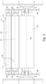
fig. 3 is a schematic front view of the compacting machine offig. 1 ; -
fig. 4 is a schematic lateral view of a first embodiment of an apparatus for finishing fabrics comprising the machine offig. 1 ; -
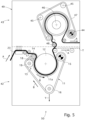
fig. 5 is a schematic lateral view of a second embodiment of an apparatus for finishing fabrics comprising the machine offig. 1 . - With reference to the attached drawings, see in particular
fig. 1 , amachine 10 for compacting fabrics T comprises aconveyor belt 11 closed in a loop and provided with at least onesegment 11a wound around a rotatingcylinder 12 so as to form a contact zone Z corresponding to an arc of a circle, in which the fabric T is suitably pressed between therotating cylinder 12 and theconveyor belt 11. - The
conveyor belt 11 is made of elastic material, such as rubber or suchlike, and abending device 13 and anintroduction device 14 are positioned in proximity to an entry side of the contact zone Z, which are configured to give the fabric T an arrangement suitable for entry into the contact zone Z. - The
introduction device 14 and thebending device 13 are disposed close to each other, on opposite sides with respect to theconveyor belt 11, in proximity to the entry side to the contact zone Z. - The rotating
cylinder 12 is rotated by means of corresponding drive means in the direction R1, so as to drag the fabric T from an entry zone to an exit zone of themachine 10. The fabric moves in a direction of advance A. - The rotating
cylinder 12 is provided with heating means, suitable to bring the fabric T to the temperature desired for the compacting treatment provided. The heating temperature can for example be variable from about 80°C to about 220°C. The heating can be carried out by means of steam, electric resistors immersed in an oil bath inside the cylinder, infrared resistors or other. Theconveyor belt 11 is in particular closed in a loop around the bendingdevice 13, amovement roller 15, for example a motorized roller, and atensioning roller 16, for example with drive of the mechanical type with screw jack, with hydraulic system or other. Theconveyor belt 11 then follows a closed loop path of advance, path of advance for short, indicated with reference B, along which it advances with uniform speed given by the rotation of themovement roller 15. - The tensioning
roller 16 applies a force adjustable in the direction Y (fig. 1 ) to tension theconveyor belt 11. During use, the latter is kept tensioned even as it advances. The maximum tension applicable to theconveyor belt 11 is considerable, since it has to extend an elastomeric belt, typically made of rubber, having a certain thickness, and it can vary from 1 to 6 tons, so as to determine an elongation thereof by a percentage varying from 4 to 20% with respect to a resting configuration, in which the belt does not undergo any tension. The thickness of theconveyor belt 11 is comprised in a range from about 8 mm to about 40 mm and preferably from about 20 mm to about 25 mm. - The
conveyor belt 11 is made of natural rubber, resistant to heat up to temperatures of about 80-90°C, or synthetic rubber, or even silicone rubber, resistant to temperatures of up to about 200-220°C. It is therefore possible to establish which type of rubber to use based on the heating temperatures provided for therotating cylinder 12 and most suitable for the composition of the fabric to be treated. - The introduction device 14 (
fig. 2 ) has a sinuous shape and can be adjusted toward or away from the bendingdevice 13 substantially in the direction C, by means of suitable adjustment means, not shown. The adjustment means can be manual, electrically motorized and associated with an encoder, pneumatic, or other. - The
introduction device 14 can be made with a sheet, preferably made of polymeric material such as polytetrafluoroethylene (PTFE) or suchlike, with characteristics such as to make it a very flexible material, with a low coefficient of friction and with high thermal and mechanical resistance. - Alternatively, the
introduction device 14 can be made by means of a sheet of fabric of aramid synthetic fiber, for example Kevlar®, treated with surface spreading of a surface layer of PTFE. - This variant also has the same characteristics of high thermal and mechanical resistance.
- The thickness of the sheet of the
introduction device 14 can be variable from about 0.1 mm to about 3 mm, therefore it is advantageously extremely thin, resistant and not bulky. - The bending
device 13, see alsofig. 3 , comprises at least one deformingroller 17, which faces theintroduction device 14, a counter-roller 18 and asupport roller 19, wherein the counter-roller 18 is interposed between the deformingroller 17 and thesupport roller 19. - The deforming
roller 17 substantially rests on the counter-roller 18. Thesupport roller 19 is in contact with the counter-roller 18. The counter-roller 18 is located between the deformingroller 17 and thesupport roller 19, and is substantially configured as a bearing which has the task of increasing the bending resistance of thebending device 13 and in particular of the deformingroller 17, which in fact deforms theconveyor belt 11, creates its bending and is subjected to the greatest stresses. Since theconveyor belt 11 is always held taut by the force applied in the direction Y by the tensioningroller 16, it can be easily understood how the deformingroller 17 is subjected to a continuous downward force, which is then unloaded onto the counter-roller 18 and onto thesupport roller 19. This force can cause a downward bending of the deformingroller 17, in particular in correspondence with its center. - This inflection phenomenon is all the more evident the more the diameter of the roller is reduced and its length increased. Considering that typical length measurements of this deforming roller reach even up to 3 meters (
fig. 3 ), it is clear that this inflection phenomenon must be counteracted. - Thanks to the fact that the deforming
roller 17 is in contact with the counter-roller 18, it can be made with a much smaller diameter than known rollers, while withstanding much greater bending stresses. This is possible thanks to the fact that the counter-roller 18 acts as a bearing, and therefore provides a contrasting constraint with respect to the downward bending to which the deformingroller 17 is subjected due to the pull exerted on it by the tensionedconveyor belt 11. - The
conveyor belt 11 can therefore perform a narrower bend, and therefore with a reduced bending radius, so as to cause a localized lengthening of theconveyor belt 11, as visible in the enlargement offig. 2 , where the segment ofconveyor belt 11 that deforms by winding around the deformingroller 17 is indicated with the letter Δ. - Measurements and experimental tests carried out by the Applicant have revealed that the linear length of the deformed segment is greater, even by 15%, than the undeformed length of this same segment in the event that the diameter of the deforming
roller 17 is equal to 90 mm, or even 25% greater than the undeformed length of this same segment in the event that the diameter of the deformingroller 17 is equal to 70 mm. In both cases, the thickness ofconveyor belt 11 is 21 mm. This increases the theoretical compacting power by up to 20% more than solutions known in the art. - This greater localized elongation amplifies the difference in peripheral speed between the bend segment in correspondence with the deforming
roller 17 and the subsequent segment in which the counter-bend is substantially provided, in correspondence with the entry of the contact zone Z. In fact, due to the localized elongation, theconveyor belt 11 travels this bend segment with a much higher peripheral speed, even 25% higher, than the uniform speed with which the belt travels the contact zone Z, which is equal to the constant speed imparted to theconveyor belt 11 by themovement roller 15. - The sudden decrease in the peripheral speed of the
conveyor belt 11 between the bend segment around the deformingroller 17 and the entry of the contact zone Z significantly increases the compacting potential of the fabric T, which is caused by the speed reduction, since the fabric follows theconveyor belt 11, being pressed against it by theintroduction device 14. - The deforming
roller 17 can have a diameter comprised between 40 mm and 80 mm, in a preferential solution about 70 mm, which is significantly smaller than the minimum diameter of about 90 mm used in similar rollers of known compacting machines with conveyor belt made of felt. - This percentage difference in the diameter of the deforming
roller 17, together with the high adhesion of therubber conveyor belt 11 that prevents slippage of the fabric T and the action of theintroduction device 14 that keeps the fabric T pressed against the belt in the introduction zone, allows to achieve a better compacting action of the machine according to the invention compared to conventional machines made according to the state of the art, by a percentage that can reach even 50%. - The deforming
roller 17, the counter-roller 18 and thesupport roller 19 can be associated at the ends with anintermediate structure 38 by means ofcorresponding supports - This
intermediate structure 38 can in turn translate, as shown schematically by the arrows V infig. 3 , by means of mechanisms not shown in the drawings, in order to move toward or away from the rotatingcylinder 12, thus allowing to move the entire unit toward or away from the rotating cylinder, and optimize the set-up of the entire fabric entry zone. - This operation of moving toward or away can be achieved by means of a mechanical screw system with manual command or with motor control and position detection encoder, or by means of a pneumatic or a hydraulic system, etc.
- Before reaching the
bending device 13 and theintroduction device 14, the fabric T passes through asteamer device 23, used to humidify it and make it more plastic, and therefore disposed upstream of these devices with reference to the direction of advance A of the fabric T. - At the exit of the contact zone Z between the
rotating cylinder 12 and theconveyor belt 11, therefore substantially when compaction is complete, the fabric T is returned aroundreturn rollers machine 10. -
Fig. 4 schematically shows a first embodiment of an apparatus for finishing fabrics T, indicated as a whole withreference number 20, and comprising themachine 10 as described above. Theapparatus 20 provides amachine 24 for stretching the fabric T, such as for example a so-called "lifter" with pin chains, of which only the end part is visible. The passage of the fabric from the stretchingmachine 24 to the compactingmachine 10 can occur with the aid of atransport device 25, to prevent tensions and therefore deformations on the fabric. - In the
present apparatus 20, themachine 10 can be combined with another compactingmachine 26 configured according to the state of the art and therefore equipped withconveyor belts modules 29 and 30 and asteamer device 31 located upstream thereof. Theother machine 26 is located downstream of thepresent machine 10 and performs other steps of compacting and finishing the fabric T. Each compactingmodule 29 and 30 is provided with a correspondingrotating cylinder conveyor belt corresponding drive roller rollers -
Fig. 5 schematically shows a second embodiment of an apparatus for finishing fabrics T, indicated as a whole withreference number 50, and comprising themachine 10 as described above. - The
apparatus 50 comprises two operating modules integrated in thesame frame 49. - In the first module (or lower module) 42 there is provided a portion of machine with
rubber conveyor belt 11, as described above, this machine portion being configured as the compactingmachine 10. - In the second module (or upper module) 43 there is provided a portion of machine configured according to the state of the art, and therefore equipped with a
conveyor belt 47 made of felt, with a heatedrotating cylinder 46 cooperating with the feltconveyor belt 47, driven by acorresponding drive roller 44 and returned around further returnrollers 45. - The
upper module 43 is located downstream of thelower module 42 with reference to the direction of advance A of the fabric, and carries out another step of compacting and stabilizing the fabric T, proving to be particularly suitable for the finishing of soft fabrics, such as plush fabric, etc. - The passage of the fabric from the
lower module 42 to theupper module 43 occurs by resting the fabric on areturn roller 48 equipped with a load cell, which synchronizes theupper module 42 with thelower module 43, imparting the minimum possible tension to the fabric in order to prevent any deformations thereof. - In this version of the
apparatus 50, the fabric T can only transit in thefirst module 42, or in bothmodules first module 42, without being subjected to compaction work in thesecond module 43. A solid line, on the other hand, represents the fabric T exiting from thesecond module 43, after having passed through both operating modules. It is clear that these are two different modes of operation of theapparatus 50, one alternative to the other. - The
present machine 10 for compacting fabrics, including the possible variants illustrated in the finishingapparatuses
Claims (15)
- Machine (10) for compacting fabrics (T), comprising a conveyor belt (11) closed in a loop, mobile along a path of advance (B) and provided with at least one segment (11a) adjacent to a rotating cylinder (12) so as to form a contact zone (Z) in which said fabric (T) is pressed between said rotating cylinder (12) and said conveyor belt (11), wherein said conveyor belt (11) is made of elastically deformable material, such as rubber or suchlike, and in proximity to an entry side of said contact zone (Z) there are positioned a bending device (13) comprising a plurality of rollers (17, 18, 19) and configured to make said conveyor belt (11) perform a bend at entry to said contact zone (Z) and an introduction device (14) cooperating with said conveyor belt (11) to exert a pressure on said fabric (T) causing it to adhere to said conveyor belt (11), thus constraining it to follow its variations in peripheral speed, characterized in that it comprises a movement roller (15) configured to make said conveyor belt (11) advance along said path of advance (B) with substantially uniform speed and in that said plurality of rollers (17, 18, 19) comprises a deforming roller (17) on which said conveyor belt (11) is wound so that the portion of the conveyor belt (11) in contact with the deforming roller (17) deforms locally in such a way as to determine a localized elongation of said portion of the conveyor belt (11) thanks to which in correspondence with the bending device (13) the conveyor belt (11) advances along the path of advance (B) with a peripheral speed greater than said uniform speed.
- Machine (10) as in claim 1, characterized in that said conveyor belt (11) is made of natural rubber or synthetic rubber or silicone rubber.
- Machine (10) as in claim 1 or 2, characterized in that the thickness of said conveyor belt (11) varies from about 8 mm to about 40 mm and in particular from about 20 mm to about 25 mm.
- Machine (10) as in any claim hereinbefore, characterized in that said introduction device (14) is made by means of a sheet of polymeric material such as polytetrafluoroethylene (PTFE) or suchlike, or by means of an aramid fiber cloth coated with polytetrafluoroethylene (PTFE).
- Machine (10) as in any claim hereinbefore, characterized in that the thickness of said introduction device (14) varies from about 0.1 mm to about 3 mm.
- Machine (10) as in any claim hereinbefore, characterized in that said plurality of rollers (17, 18, 19) of said bending device (13) comprises at least one counter-roller (18) in contact with said deforming roller (17), on which the latter rests during their rotation around a first axis of rotation (X1) and a second axis of rotation (X2), respectively, which are parallel to each other.
- Machine (10) as in claim 6, characterized in that said plurality of rollers (17, 18, 19) of said bending device (13) comprises a support roller (19) in contact with said counter-roller (18) on which the latter rests during their rotation around said second axis of rotation (X2) and a third axis of rotation (X3), respectively, which are parallel to each other and to said first axis of rotation (X1).
- Machine (10) as in any claim hereinbefore, characterized in that the extent of said localized deformation is a function of the diameter of said deforming roller (17), which is comprised between approximately 40 mm and approximately 80 mm.
- Machine (10) as in any claim hereinbefore, characterized in that it comprises a single movement roller (15) and a tensioning roller (16) comprising a mechanical or hydraulic drive to exert an adjustable force on said conveyor belt (11) in a substantially vertical direction (Y).
- Machine (10) as in claim 10, characterized in that said conveyor belt (11) is closed in a loop around said bending device (13), said movement roller (15) and said tensioning roller (16).
- Machine (10) as in any claim hereinbefore, characterized in that it comprises a steamer device (23) configured to humidify the fabric (T) and make it more plastic, and disposed upstream of said bending device (13) and said introduction device (14).
- Apparatus (20; 50) for finishing fabrics, comprising a first compacting operating module (42) and at least a second compacting operating module (29, 30; 43), disposed downstream of said first module (42) with reference to a direction of advance (A) of the fabric (T), wherein said first module (42) comprises said compacting machine (10) as in any claim hereinbefore and wherein said second module (29, 30; 43) comprises a rotating cylinder (32, 33; 46) and a felt compacting belt (27, 28; 47) cooperating with the respective rotating cylinder (32, 33; 46), closed in a loop on a corresponding drive roller (35, 37; 44) which drives it in movement and around additional return rollers (36, 37; 45).
- Apparatus (20; 50) as in claim 12, comprising at least one fabric stretching machine (24) disposed upstream of said machine (10), with reference to said direction of advance (A) of the fabric (T), and a transport device (25) which carries the fabric (T) from said fabric stretching machine (24) to said machine (10).
- Apparatus (20; 50) as in claim 12 or 13, wherein said second module (29, 30) is configured as another machine (26) comprising one or more of said felt compacting modules (29, 30), disposed downstream with respect to said first module (42) with reference to said direction of advance (A) of the fabric (T).
- Apparatus (20; 50) as in claim 12 or 13, wherein said second module (43) is integrated into a same frame (49) also comprising said first module (42); said second module (43) being disposed downstream with respect to said first module (42) with reference to the direction of advance (A) of the fabric (T).
Applications Claiming Priority (1)
| Application Number | Priority Date | Filing Date | Title |
|---|---|---|---|
| IT102023000011418A IT202300011418A1 (en) | 2023-06-06 | 2023-06-06 | TEXTILE COMPACTION MACHINE |
Publications (2)
| Publication Number | Publication Date |
|---|---|
| EP4474563A1 true EP4474563A1 (en) | 2024-12-11 |
| EP4474563A8 EP4474563A8 (en) | 2025-03-26 |
Family
ID=87889760
Family Applications (1)
| Application Number | Title | Priority Date | Filing Date |
|---|---|---|---|
| EP24179941.0A Pending EP4474563A1 (en) | 2023-06-06 | 2024-06-04 | Macchina di compattazione di tessuti |
Country Status (2)
| Country | Link |
|---|---|
| EP (1) | EP4474563A1 (en) |
| IT (1) | IT202300011418A1 (en) |
Citations (5)
| Publication number | Priority date | Publication date | Assignee | Title |
|---|---|---|---|---|
| US3035512A (en) * | 1958-05-19 | 1962-05-22 | Clupak Inc | Flexible nip loading arrangement |
| EP1357217A2 (en) * | 2002-07-26 | 2003-10-29 | Muzzi Costruzioni Meccaniche S.R.L. | Fabric finishing range and process for fabric finishing |
| EP3754088A1 (en) | 2019-06-17 | 2020-12-23 | Santex Rimar Group S.r.l. | Apparatus for compacting a continuous textile substrate by means of elastic belt |
| EP3786331A1 (en) * | 2019-08-29 | 2021-03-03 | Lafer S.p.A. | Combined compacting machine for fabrics and corresponding compacting method |
| EP3607132B1 (en) * | 2017-04-07 | 2021-10-27 | Red Carpet S.r.l. | A shrinking machine |
Family Cites Families (1)
| Publication number | Priority date | Publication date | Assignee | Title |
|---|---|---|---|---|
| FR1055389A (en) * | 1952-05-03 | 1954-02-18 | Device for inserting fabrics into a friction calender |
-
2023
- 2023-06-06 IT IT102023000011418A patent/IT202300011418A1/en unknown
-
2024
- 2024-06-04 EP EP24179941.0A patent/EP4474563A1/en active Pending
Patent Citations (5)
| Publication number | Priority date | Publication date | Assignee | Title |
|---|---|---|---|---|
| US3035512A (en) * | 1958-05-19 | 1962-05-22 | Clupak Inc | Flexible nip loading arrangement |
| EP1357217A2 (en) * | 2002-07-26 | 2003-10-29 | Muzzi Costruzioni Meccaniche S.R.L. | Fabric finishing range and process for fabric finishing |
| EP3607132B1 (en) * | 2017-04-07 | 2021-10-27 | Red Carpet S.r.l. | A shrinking machine |
| EP3754088A1 (en) | 2019-06-17 | 2020-12-23 | Santex Rimar Group S.r.l. | Apparatus for compacting a continuous textile substrate by means of elastic belt |
| EP3786331A1 (en) * | 2019-08-29 | 2021-03-03 | Lafer S.p.A. | Combined compacting machine for fabrics and corresponding compacting method |
Also Published As
| Publication number | Publication date |
|---|---|
| IT202300011418A1 (en) | 2024-12-06 |
| EP4474563A8 (en) | 2025-03-26 |
Similar Documents
| Publication | Publication Date | Title |
|---|---|---|
| EP3938568A1 (en) | Machine for compacting textile structures of fabrics and corresponding compaction method | |
| JP7583427B2 (en) | Compacting device for continuous fiber fabrics with elastic belts | |
| US2084367A (en) | Apparatus for treating cloth | |
| CN108884636B (en) | Device and method for changing a clothing of a paper machine | |
| US3995457A (en) | Continuous padding type dyeing machine | |
| CN113508200A (en) | a shrinking machine | |
| US20060112526A1 (en) | Apparatus and method for shrinking continuous textile substrates | |
| KR0153461B1 (en) | Compressive shrinking apparatus utilizing an improved impact blade | |
| US2120536A (en) | Method and apparatus for preshrinking cloth | |
| US4575909A (en) | Apparatus for treating fabric for shrinkage | |
| US3156964A (en) | Weft correcting apparatus | |
| CN103132215A (en) | Carbon fiber weaving warp tension device capable of compensating and sending warp actively | |
| CN212051975U (en) | Raising machine capable of controlling tension in weft direction | |
| CN101111633B (en) | Method and device for finishing tented web fabrics | |
| EP0955403A1 (en) | Method and apparatus for the compressive shrinking of textile fabrics | |
| US3524219A (en) | Finishing of laminar materials | |
| US3253433A (en) | Pressure roller devices for the wet treatment of textile materials | |
| CA1135038A (en) | Machine for and method of producing treating or finishing a fabric | |
| JP2020204137A (en) | Compact apparatus for continuous fiber fabric using elastic belt | |
| EP4524310B1 (en) | Alignment device equipped with a device for positioning a fabric release cylinder for textile machines | |
| JP3882225B2 (en) | Liquid ammonia processing equipment | |
| US2943375A (en) | Stretching machine for dryer felts and the like | |
| US4034702A (en) | Apparatus for manufacturing bias fabric | |
| US2040454A (en) | Apparatus for preshrinking cloth | |
| EP0087399B1 (en) | Apparatus for transversely stretching a foil of plastic material |
Legal Events
| Date | Code | Title | Description |
|---|---|---|---|
| PUAI | Public reference made under article 153(3) epc to a published international application that has entered the european phase |
Free format text: ORIGINAL CODE: 0009012 |
|
| STAA | Information on the status of an ep patent application or granted ep patent |
Free format text: STATUS: THE APPLICATION HAS BEEN PUBLISHED |
|
| AK | Designated contracting states |
Kind code of ref document: A1 Designated state(s): AL AT BE BG CH CY CZ DE DK EE ES FI FR GB GR HR HU IE IS IT LI LT LU LV MC ME MK MT NL NO PL PT RO RS SE SI SK SM TR |
|
| STAA | Information on the status of an ep patent application or granted ep patent |
Free format text: STATUS: REQUEST FOR EXAMINATION WAS MADE |
|
| 17P | Request for examination filed |
Effective date: 20250610 |