EP4474526A1 - Re-activation process of gas diffusion electrode - Google Patents
Re-activation process of gas diffusion electrode Download PDFInfo
- Publication number
- EP4474526A1 EP4474526A1 EP23177314.4A EP23177314A EP4474526A1 EP 4474526 A1 EP4474526 A1 EP 4474526A1 EP 23177314 A EP23177314 A EP 23177314A EP 4474526 A1 EP4474526 A1 EP 4474526A1
- Authority
- EP
- European Patent Office
- Prior art keywords
- gde
- working electrode
- electrode
- cathode
- anodic
- Prior art date
- Legal status (The legal status is an assumption and is not a legal conclusion. Google has not performed a legal analysis and makes no representation as to the accuracy of the status listed.)
- Withdrawn
Links
Images




Classifications
-
- C—CHEMISTRY; METALLURGY
- C25—ELECTROLYTIC OR ELECTROPHORETIC PROCESSES; APPARATUS THEREFOR
- C25B—ELECTROLYTIC OR ELECTROPHORETIC PROCESSES FOR THE PRODUCTION OF COMPOUNDS OR NON-METALS; APPARATUS THEREFOR
- C25B1/00—Electrolytic production of inorganic compounds or non-metals
- C25B1/01—Products
- C25B1/23—Carbon monoxide or syngas
-
- C—CHEMISTRY; METALLURGY
- C25—ELECTROLYTIC OR ELECTROPHORETIC PROCESSES; APPARATUS THEREFOR
- C25B—ELECTROLYTIC OR ELECTROPHORETIC PROCESSES FOR THE PRODUCTION OF COMPOUNDS OR NON-METALS; APPARATUS THEREFOR
- C25B1/00—Electrolytic production of inorganic compounds or non-metals
- C25B1/01—Products
- C25B1/02—Hydrogen or oxygen
- C25B1/04—Hydrogen or oxygen by electrolysis of water
-
- C—CHEMISTRY; METALLURGY
- C25—ELECTROLYTIC OR ELECTROPHORETIC PROCESSES; APPARATUS THEREFOR
- C25B—ELECTROLYTIC OR ELECTROPHORETIC PROCESSES FOR THE PRODUCTION OF COMPOUNDS OR NON-METALS; APPARATUS THEREFOR
- C25B1/00—Electrolytic production of inorganic compounds or non-metals
- C25B1/01—Products
- C25B1/27—Ammonia
-
- C—CHEMISTRY; METALLURGY
- C25—ELECTROLYTIC OR ELECTROPHORETIC PROCESSES; APPARATUS THEREFOR
- C25B—ELECTROLYTIC OR ELECTROPHORETIC PROCESSES FOR THE PRODUCTION OF COMPOUNDS OR NON-METALS; APPARATUS THEREFOR
- C25B1/00—Electrolytic production of inorganic compounds or non-metals
- C25B1/01—Products
- C25B1/28—Per-compounds
- C25B1/30—Peroxides
-
- C—CHEMISTRY; METALLURGY
- C25—ELECTROLYTIC OR ELECTROPHORETIC PROCESSES; APPARATUS THEREFOR
- C25B—ELECTROLYTIC OR ELECTROPHORETIC PROCESSES FOR THE PRODUCTION OF COMPOUNDS OR NON-METALS; APPARATUS THEREFOR
- C25B1/00—Electrolytic production of inorganic compounds or non-metals
- C25B1/50—Processes
-
- C—CHEMISTRY; METALLURGY
- C25—ELECTROLYTIC OR ELECTROPHORETIC PROCESSES; APPARATUS THEREFOR
- C25B—ELECTROLYTIC OR ELECTROPHORETIC PROCESSES FOR THE PRODUCTION OF COMPOUNDS OR NON-METALS; APPARATUS THEREFOR
- C25B11/00—Electrodes; Manufacture thereof not otherwise provided for
- C25B11/04—Electrodes; Manufacture thereof not otherwise provided for characterised by the material
- C25B11/042—Electrodes formed of a single material
-
- C—CHEMISTRY; METALLURGY
- C25—ELECTROLYTIC OR ELECTROPHORETIC PROCESSES; APPARATUS THEREFOR
- C25B—ELECTROLYTIC OR ELECTROPHORETIC PROCESSES FOR THE PRODUCTION OF COMPOUNDS OR NON-METALS; APPARATUS THEREFOR
- C25B15/00—Operating or servicing cells
-
- C—CHEMISTRY; METALLURGY
- C25—ELECTROLYTIC OR ELECTROPHORETIC PROCESSES; APPARATUS THEREFOR
- C25B—ELECTROLYTIC OR ELECTROPHORETIC PROCESSES FOR THE PRODUCTION OF COMPOUNDS OR NON-METALS; APPARATUS THEREFOR
- C25B15/00—Operating or servicing cells
- C25B15/02—Process control or regulation
- C25B15/023—Measuring, analysing or testing during electrolytic production
- C25B15/025—Measuring, analysing or testing during electrolytic production of electrolyte parameters
- C25B15/029—Concentration
- C25B15/031—Concentration pH
-
- C—CHEMISTRY; METALLURGY
- C25—ELECTROLYTIC OR ELECTROPHORETIC PROCESSES; APPARATUS THEREFOR
- C25B—ELECTROLYTIC OR ELECTROPHORETIC PROCESSES FOR THE PRODUCTION OF COMPOUNDS OR NON-METALS; APPARATUS THEREFOR
- C25B15/00—Operating or servicing cells
- C25B15/02—Process control or regulation
- C25B15/023—Measuring, analysing or testing during electrolytic production
- C25B15/025—Measuring, analysing or testing during electrolytic production of electrolyte parameters
- C25B15/033—Conductivity
-
- C—CHEMISTRY; METALLURGY
- C25—ELECTROLYTIC OR ELECTROPHORETIC PROCESSES; APPARATUS THEREFOR
- C25B—ELECTROLYTIC OR ELECTROPHORETIC PROCESSES FOR THE PRODUCTION OF COMPOUNDS OR NON-METALS; APPARATUS THEREFOR
- C25B3/00—Electrolytic production of organic compounds
- C25B3/01—Products
- C25B3/03—Acyclic or carbocyclic hydrocarbons
-
- C—CHEMISTRY; METALLURGY
- C25—ELECTROLYTIC OR ELECTROPHORETIC PROCESSES; APPARATUS THEREFOR
- C25B—ELECTROLYTIC OR ELECTROPHORETIC PROCESSES FOR THE PRODUCTION OF COMPOUNDS OR NON-METALS; APPARATUS THEREFOR
- C25B3/00—Electrolytic production of organic compounds
- C25B3/01—Products
- C25B3/07—Oxygen containing compounds
-
- C—CHEMISTRY; METALLURGY
- C25—ELECTROLYTIC OR ELECTROPHORETIC PROCESSES; APPARATUS THEREFOR
- C25B—ELECTROLYTIC OR ELECTROPHORETIC PROCESSES FOR THE PRODUCTION OF COMPOUNDS OR NON-METALS; APPARATUS THEREFOR
- C25B3/00—Electrolytic production of organic compounds
- C25B3/20—Processes
- C25B3/25—Reduction
-
- C—CHEMISTRY; METALLURGY
- C25—ELECTROLYTIC OR ELECTROPHORETIC PROCESSES; APPARATUS THEREFOR
- C25B—ELECTROLYTIC OR ELECTROPHORETIC PROCESSES FOR THE PRODUCTION OF COMPOUNDS OR NON-METALS; APPARATUS THEREFOR
- C25B3/00—Electrolytic production of organic compounds
- C25B3/20—Processes
- C25B3/25—Reduction
- C25B3/26—Reduction of carbon dioxide
-
- C—CHEMISTRY; METALLURGY
- C25—ELECTROLYTIC OR ELECTROPHORETIC PROCESSES; APPARATUS THEREFOR
- C25B—ELECTROLYTIC OR ELECTROPHORETIC PROCESSES FOR THE PRODUCTION OF COMPOUNDS OR NON-METALS; APPARATUS THEREFOR
- C25B9/00—Cells or assemblies of cells; Constructional parts of cells; Assemblies of constructional parts, e.g. electrode-diaphragm assemblies; Process-related cell features
- C25B9/17—Cells comprising dimensionally-stable non-movable electrodes; Assemblies of constructional parts thereof
- C25B9/19—Cells comprising dimensionally-stable non-movable electrodes; Assemblies of constructional parts thereof with diaphragms
Definitions
- the present invention relates to a method of re-activation for long-term stable operation of a metal-based gas diffusion electrode (GDE) in the electrocatalytic conversion of gaseous reactants into economically interesting reaction products.
- GDE metal-based gas diffusion electrode
- Such metal based GDE's, and in particular carbon free metal based GDEs are particularly useful in the electrochemical conversion of gaseous reactants such as CO 2 , CO, N 2 , NO x or O 2 into bulk chemicals and fuels such as Syngas, Formic Acid, Methanol, Ethanol, Ethane, Ethylene, Methane, Ammonia, Hydroxylamine, Hydrogen Peroxide and the like.
- a GDE is a combination of porous structures exhibiting a hydrophilic and a hydrophobic side. It is generally composed of a catalyst layer (CL), a gas diffusion layer (GDL) and optionally a current collector (CC) as shown in Figure 1 .
- a GDE allows the direct supply of gases via the hydrophobic side to the liquid medium where electrochemical processes take place. Because of their low mass transfer resistance, the use of GDEs is promising for electrochemical processes with gaseous reactants since they overcome the poor mass transport of gases that have a limited solubility, towards the electrode. Because of their high porosity, GDEs have a reactive surface area much larger than their geometrical area (projected surface area), which is favorable for the process productivities.
- the GDL is a porous medium that facilitates transport of gaseous reactants to and gaseous products from the CL and consists of a macro/meso/nano-porous layer either with or without a micro-porous layer (MPL).
- MPL micro-porous layer
- CCU CO 2 Conversion and Utilization
- ECR Electrochemical CO 2 reduction
- GDEs gas diffusion electrodes
- ECR electrochemical conversion activity
- a qualified electrode must fulfill the requirements of 1) sufficiently high current density and 2) stable and significantly high Faradaic Efficiency (FE) towards the targeted product.
- FE Faradaic Efficiency
- industrial relevant production of formic acid requires electrodes with a current density of at least 100 mA/cm 2 and an FE of 70 ⁇ 10%.
- the present electrodes for ECR of CO 2 fail in providing stable long-term operation ( ⁇ 1000 h) for electrochemical conversion activity.
- DCP deep cathodic polarization
- AP anodic polarization
- the well known electrocatalyst CO 2 to formic acid conversion includes Sn, Bi, In or alloys of these metals.
- These metal based GDE's have not shown promising results in long-term operation ( ⁇ 1000 h), as required for industrial set-up ( Van Daele, K., De Mot, B., Pupo, M., Daems, N., Pant, D., Kortlever, R. and Breugelmans, T., 2021.
- Sn-based electrocatalyst stability a crucial piece to the puzzle for the electrochemical CO2 reduction toward formic acid.
- ACS Energy Letters, 6(12), pp.4317-4327 a crucial piece to the puzzle for the electrochemical CO2 reduction toward formic acid.
- the aforementioned claim is about the set-up /design of the reactor, including the electrodes used in the form of Sn-doped granules comprising of Sn/Sn-Zn alloy. Still, even with these Sn-granule as cathode, the formate FE is dropped from 60% to 45% in ⁇ 4 h of operation.
- the cathode activity is recovered by combining two methods: 1) chemical method treating Sn-granules with 11 wt% nitric acid and 2) Polarity reversal, with 1 A applied for 5 minutes.
- the requirement of an electrode with a larger surface is not a preferred option due to electrode integrity (mechanical strength) of the large GDE, maintaining a uniform current distribution and the leakproof nature of the GDE ( Perry, S.C., de León, C.P. and Walsh, F.C., 2020. The Design, Performance and Continuing Development of Electrochemical Reactors for Clean Electrosynthesis. Journal of The Electrochemical Society, 167(15), p.155525 ).
- the present invention is directed to a method of operating an electrochemical cell comprising a metal based GDE as working electrode, a counter electrode, and an electrolyte in the electrochemical conversion of a gaseous reactant into bulk chemicals at the working electrode, said method of operation being characterized in maintaining the pH of the electrolyte within a useful range of 2 units of its initial value, and in applying an inverse electrical pulse at regular intervals to the metal based GDE working electrode which is the electrode where the electrochemical reaction of interest occurs.
- the metal based GDE working electrode is used in the reductive conversion of gaseous reactants into bulk chemicals, such as the electrochemical CO 2 reduction into formic acid;
- the GDE working electrode is the cathode, and the inverse electrical pulse will be an anodic pulse.
- the present invention provides a method of operating an electrochemical cell comprising a metal based GDE working electrode as cathode, an anode, and an electrolyte in the electrochemical conversion of a gaseous reactant into bulk chemicals at the working electrode, said method of operation being characterized in maintaining the pH and conductivity of the electrolyte within a range of 2 units of its initial value, and in applying an anodic pulse to the working electrode at regular intervals.
- the electrochemical cell comprises an anode and a cathode compartment and wherein the method is characterized in maintaining the pH of the catholyte within a range of 2 units of its initial value, and in applying an inverse electrical pulse, in particular an anodic pulse to the GDE working electrode at regular intervals.
- the anodic pulse applied to the working electrode consists of a current of 50-200 mA cm -2 , preferably applied for at least 30 seconds; in particular a current of at least 100 mA cm -2 , preferably applied for at least 1 minutes.
- the anodic pulse consists of a charge of 1.5-10 Coulomb (C) cm -2 applied to the working electrode (GDE); in particular a charge of at least 6 C cm -2 applied to the working electrode (GDE).
- the anodic pulses are applied at intervals selected to maintain a sufficiently high current density and stable and significantly high Faradaic Efficiency (FE) towards the targeted product.
- the pulses are applied at intervals to maintain or restore the Faradaic Efficiency (FE) towards the targeted product within a window of 20% of its initial value before pre-pulsing.
- the anodic pulses are applied to the cathode at regular intervals, such as every hour, every 2 hours, every 3 hours, every 4 hours , every 5 hours, or longer duration.
- the anodic pulses are applied to the cathode at intervals starting at 6 hours, in particular starting at 12 hours, more in particular starting at 24 hours, even more in particular every 48 hours.
- the gaseous reactant is selected from CO 2 , CO, N 2 , NO x or O 2 ; in particular CO 2 .
- the bulk chemicals are selected from Syngas, Formic Acid, Methanol, Ethanol, Ethane, Ethylene, Methane, Ammonia, Hydroxylamine, Hydrogen peroxide and the like.
- the electrolyte is selected from KHCO 3 , NaHCO 3 , K 2 CO 3 , Na 2 CO 3 , KCl, NaCl, K 2 HPO 4 , KH 2 PO 4 , Na 2 HPO 4 , NaH 2 PO 4 , H 2 SO 4 , HClO 4 , H 3 PO 4 and K 2 SO 4 , K 3 PO 4 , Na 2 SO 4 , NaClO 4 , Na 3 PO 4 , KOH, NaOH; in a particular embodiment the electrolyte is selected from KHCO 3 (0.5 - 2 M), H 2 SO 4 (0.05 - 0.5 M) and K 2 SO 4 (0.5 - 1 M).
- This invention encompasses a stable ECR process using a metal-based Gas Diffusion Electrode (GDE), specifically for the electrochemical conversion of CO 2 , such as for example to formate/formic acid.
- GDE Gas Diffusion Electrode
- ECR electrochemical CO 2 reduction
- metal-based GDE such as Bi/Sn-GDE, In, Zn, and the like as working electrode well known.
- these electrodes have been prone to failure for stable long-term operation ( ⁇ 1000 h) for ECR activity, which hampers industrial application.
- the present invention provides a method (process) and equipment needed to increase the metal-based GDEs' longevity and stability to increase the Faradaic efficiency (FE), when used in a electrochemical cell for ECR activity. This is imperative to get an overall energy efficient process as well.
- FE Faradaic efficiency
- the process combines the intrinsic property of the electrolyte used, and changes occurring due to inducing the polarity change at the electrode to achieve the aforementioned claim, and was found particularly useful for carbon free metal-based GDEs, such as the carbon free Sn-GDE disclosed in the earlier patent application of the applicant WO2022013042A1 .
- a carbon-free metal-based GDE is used; in particular a carbon free Sn-GDE; even more in particular the carbon-free Sn-GDE electrode prepared using the methodology as disclosed in patent no. WO2022013042A1 .
- the equipment generally refers to an electrochemical cell comprising a metal based GDE working electrode as cathode, an anode, in particular an inert anode, such as an inert Pt anode, and an electrolyte, whereby a gas is fed into the GDE with electrolyte permeating the opposite side of the GDE, said cell being used for causing current to flow externally through a load circuit connecting the anode and the cathode.
- a metal based GDE working electrode as cathode
- an anode in particular an inert anode, such as an inert Pt anode
- electrolyte an electrolyte
- anode and cathode compartments are typically separated by means of ion-conducting membranes such as anion exchange membrane (AEM), Cation exchange membrane (CEM) or bipolar membrane (BPM), wherein each of the anode compartment and the cathode compartment respectively comprise an anolyte and a catholyte solution.
- AEM anion exchange membrane
- CEM Cation exchange membrane
- BPM bipolar membrane
- the method according to the invention of operating such equipment in the electrochemical conversion of gaseous reactants such as CO 2 , CO, N 2 , or O 2 into bulk chemicals and fuels such as Syngas, Formic Acid, Methanol, Ethanol, Ethane, Ethylene, Methane, Ammonia, and the like; is characterized in maintaining the pH of the electrolyte within a range of 2 units of its initial value, and in applying anodic pulsing to the GDE working electrode, i.e. the cathode, at regular intervals.
- the method is characterized in maintaining the pH of the catholyte within a range of 2 units of its initial value, and in applying anodic pulsing to the GDE working electrode, i.e. the cathode, at regular intervals.
- the electrocatalytic instability and observed deactivation or degradation of the metal-based GDEs can be associated with changes in the electrode's intrinsic property and its local environment (such as the concentration of K + , HCOO - , CO 3 2- , etc.) during the electrolysis process.
- ECR Electrochemical CO 2 Reduction
- the observed decrease in formate ion production at the GDE cathode is directly associated with a drop in pH of the catholyte, which favours the competing hydrogen evolution reaction (HER).
- Controlling the pH of the catholyte and maintaining it within 2 units, in particular within 1 unit from its initial value, i.e. the pH value of the pristine catholyte at the operational start of the electrochemical process counteracts such reaction to occur.
- the Faradaic efficiency (FE) describes the selectivity of an electrochemical process towards a specific target product and is defined as the amount (moles) of collected product relative to the amount that could be produced from the total charge passed, expressed as a fraction or a percentage.
- the anodic pulse is meant to refer to an inverse current or potential pulse applied to the working electrode, i.e. the electrode in the electrochemical system on which the reaction of interest is occurring.
- the working electrode is called cathode or anode, respectively.
- the GDE working electrode is the cathode but the invention is not restricted thereto.
- the pulse is inverse with respect to its operational charge in the electrochemical conversion of the gaseous reactant into bulk chemicals at the working electrode. For example during ECR, a negative potential (reducing current) is applied to the GDE working electrode and the anodic pulse will consist of a positive (inverse) potential (oxidizing current) applied to the GDE working electrode.
- the anodic pulse consists of a current of 50-200 mA cm -2 , preferably applied for at least 30 seconds; in particular a current of at least 100 mA cm -2 , preferably applied for at least 1 minutes to the GDE working electrode (cathode).
- the anodic pulse consists of a constant current of 50-200 mA cm -2 , preferably applied for at least 30 seconds; in particular a constant current of at least 100 mA cm -2 , preferably applied for at least 1 minutes to the GDE working electrode (cathode).
- the anodic pulse consists of a positive charge of 1.5-10 Coulomb (C) cm -2 applied to the cathode; in particular a charge of at least 6 C cm -2 applied to the cathode.
- the anodic pulse consists of a constant charge of 1.5-10 Coulomb (C) cm -2 applied to the cathode; in particular a constant charge of at least 6 C cm -2 applied to the cathode.
- the anodic pulse consists of a current of 50-200 mA cm -2 , preferably applied for at least 30 seconds; in particular a current of at least 100 mA cm -2 , preferably applied for at least 1 minutes, in particular up to about 10 min, more in particular from about 4 to 8 min, to the cathode, wherein said anodic pulse is applied at regular intervals starting at 6 hours, in particular starting at 12 hours, more in particular starting at 24 hours, even more in particular every 48 hours.
- the anodic pulse consists of a constant current of 50-200 mA cm -2 , preferably applied for at least 30 seconds; in particular a constant current of at least 100 mA cm -2 , preferably applied for at least 1 minutes, in particular up to about 10 min, more in particular from about 4 to 8 min, to the cathode, wherein said anodic pulse is applied at regular intervals starting at 6 hours, in particular starting at 12 hours, more in particular starting at 24 hours, even more in particular every 48 hours.
- the anodic pulse consists of a charge of 1.5-10 Coulomb (C) cm -2 applied to the cathode; in particular a charge of at least 6 C cm-2 applied to the cathode, wherein said anodic pulse is applied at regular intervals starting at 6 hours, in particular starting at 12 hours, more in particular starting at 24 hours, even more in particular every 48 hours.
- the anodic pulse consists of a constant charge of 1.5-10 Coulomb 1.1.5-10 Coulomb (C) cm -2 applied to the cathode; in particular a constant charge of at least 6 C cm -2 applied to the cathode, wherein said anodic pulse is applied at regular intervals starting at 6 hours, in particular starting at 12 hours, more in particular starting at 24 hours, even more in particular every 48 hours.
- the anodic pulse can be expressed as the magnitude of electrical charge, i.e. 6 C cm -2 applied to the cathode.
- the magnitude of electrical charge i.e. 6 C cm -2 applied to the cathode.
- this charge is enough to change the polarity around the double-layer charging area that is majorly impacted, the recovery of FE obtained by such a small charge (15-60 C) does not have a lasting impact on the electrode's selectivity for ECR. Only a small increase of 10-15% in FE is observed, which drops to its pre-pulsing value within 24-48 h.
- the FE increases by 20 to 30% at a charge between 240 C and 360 C, which has a long-lasting impact on the electrode's ECR selectivity. It is hypothesized that such high charge value is enough to oxidise the metal catalyst present within the GDE, for example from Sn metal to SnO 2 , and that it also removes any impurities deposited on the electrode during the long-term process, working also as a cleaning method for the electrode.
- the Sn-GDE is subjected to cathodic potential post the anodic pulse as herein disclosed, it reduces back to metallic tin, making the electrode more porous, increasing the three-phase interphase, and increasing the FE of formate.
- condition I The combination of maintaining catholyte pH and conductivity (condition I ) and anodic pulsing (condition II), helps to restore the initial selectivity of the electrode towards ECR and operate the electrochemical cell for the duration of at least 1000 h and beyond,. At any moment, failing to comply with these conditions (conditions I and II) can lead to a drop in the selectivity of the electrode's activity towards ECR.
- metal-based GDEs and in particular Bi-GDE or Sn-GDE can be reactivated to its initial form/activity, by the combined effect of condition I, i.e. keeping the electrolyte pH within 2 units from its initial pH, more in particular keeping the electrolyte, even more in particular keeping the catholyte at a slightly alkaline (pH from about 7 to 9) pH , and condition II, with anodic pulses for a few minutes (4-8 minutes) at a fixed interval of 48 h to prolong the Sn-GDE activity towards ECR.
- condition I i.e. keeping the electrolyte pH within 2 units from its initial pH, more in particular keeping the electrolyte, even more in particular keeping the catholyte at a slightly alkaline (pH from about 7 to 9) pH
- condition II with anodic pulses for a few minutes (4-8 minutes) at a fixed interval of 48 h to prolong the Sn-GDE activity towards ECR.
- condition II is expressed as anodic pulse with a charge of at least 120 Coulomb (C); in particular an anodic pulse with a charge of at least 240 C; more in particular an anodic pulse with a charge up to about 600 C; even more in particular with an anodic pulse from about and between 240 C to 360 C.
- C Coulomb
- an electrochemical cell for Electrochemical CO 2 reduction comprising a Sn-GDE as disclosed in WO2022013042A1 is initially stable for 200 h, at a current density of 100 mA/cm 2 .
- the stability of the electrode is expressed in terms of the Faradaic efficiency (FE) of formate ions produced from ECR.
- FE Faradaic efficiency
- the FE of formate drops from 75% to 25% ( Figure 2 ).
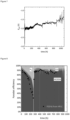
- the constant decrease in the FE of formate ions could be directly associated with the drop in pH of the catholyte, which favours HER, a competing reaction with ECR ( Figure 3 ).
- anodic pulse is then applied to the cathode, as shown in Figure 4 , to restore the electrode activity to its initial level.
- Example 1 Sn-GDE in a flow cell
- ElectroCell ® microflow cell with an effective active area of working electrode as 10 ⁇ cm 2 . All the experiments were conducted in a galvanostatic mode with a current density of 100 mA/cm 2 ( Figure 5 ). Prior to each electrochemical experiment, the catholyte (0.5 M KHCO 3 ) was saturated with CO 2 overnight (6-8 h). BPC GO ® , a flow meter, was used at the outlet of the cell to monitor the exit flow of gas from the cell. To maintain identical reaction conditions, the application of current (I) was delayed until a stable signal of outlet CO 2 was recorded for 20-30 min by the BPC GO ® flowmeter.
- the cell was designed with a flow-through mode of operation ( Figure 6 ), with an carbon free Sn-GDE (as disclosed in patent no. WO2022013042A1 ) of 100 cm 2 geometrical area as Working Electrode, dimensionally stable anode (DSA) as Counter Electrode and Ag/AgCl as reference electrode (RE).
- Sn-GDE carbon free Sn-GDE
- DSA dimensionally stable anode
- RE reference electrode
- the pH and conductivity of the bulk catholyte were monitored throughout these experiments.
- the changes in the WE potential were monitored throughout the experiment ( Figure 7 ).
- the mode of the experiment is a single partial pass, achieved by circulating the electrolyte from a large feedstock reservoir (5 L), contrary to the electrolyte volume (calculated for both anode and cathode).
- the catholyte is periodically refreshed to maintain the pH and conductivity of the electrolyte in the range of 7.8-6.5, and 45-80 mS/cm, respectively.
- GC gas chromatograph
- HPLC High-performance liquid chromatography
- a constant current is applied across the electrochemical cell to achieve a current density of 100 mA/cm 2 (the commercially relevant current density).
- the pH and conductance of the bulk catholyte were monitored ( Figure 2 ). Liquid samples were collected periodically from the bulk catholyte and analyzed for formate ions with HPLC. For gas analysis, the experimental set-up was connected with headspace GC.
- the FE of formic acid production from ECR by using a Bi GDE (a GDE based on Bi powder prepared exactly the same way as Sn GDE described in WO2022013042A1 ) is demonstrated in Figure 8 .
- the FE to formic acid was significantly recovered by pulsing (starting from 280 h, every 12 h an anodic pulsing was applied) after the FE to formic acid has decreased from initially 95% to around 70% at 260 h.
- Figure 9 directly shows the impact of the pulsing method.
- the FE towards formic acid After the first pulse (1000 mA for 2 min), the FE towards formic acid increased from 70% to around 87% and started to level down with time. However, with periodic pulsing (1000 mA for 1 min every 12 hour), the FE towards formic acid can be maintained in a window of 85-90%, promising a stable and controlled process to produce formic acid electrochemically from CO 2 .
Landscapes
- Chemical & Material Sciences (AREA)
- Organic Chemistry (AREA)
- Engineering & Computer Science (AREA)
- Chemical Kinetics & Catalysis (AREA)
- Electrochemistry (AREA)
- Materials Engineering (AREA)
- Metallurgy (AREA)
- Inorganic Chemistry (AREA)
- Analytical Chemistry (AREA)
- Automation & Control Theory (AREA)
- Electrolytic Production Of Non-Metals, Compounds, Apparatuses Therefor (AREA)
Abstract
The present invention relates to a method of re-activation and long-term stable operation of a metal based gas diffusion electrode (GDE), and the use thereof in the electrocatalytic conversion of gaseous reactants into economically interesting reaction products. Using the operational method of the present invention such metal based GDEs, and in particular carbon free metal-based GDEs are particularly useful in the electrochemical conversion of gaseous reactants such as CO<sub>2</sub>, CO, N<sub>2</sub>, or O<sub>2</sub> into bulk chemicals and fuels such as Syngas, Formic Acid, Methanol, Ethanol, Ethane, Ethylene, Methane, Ammonia, and the like for durable operation (> 1000 hours).
Description
- The present invention relates to a method of re-activation for long-term stable operation of a metal-based gas diffusion electrode (GDE) in the electrocatalytic conversion of gaseous reactants into economically interesting reaction products. Using the operational method of the present invention such metal based GDE's, and in particular carbon free metal based GDEs are particularly useful in the electrochemical conversion of gaseous reactants such as CO2, CO, N2, NOx or O2 into bulk chemicals and fuels such as Syngas, Formic Acid, Methanol, Ethanol, Ethane, Ethylene, Methane, Ammonia, Hydroxylamine, Hydrogen Peroxide and the like.
- A GDE is a combination of porous structures exhibiting a hydrophilic and a hydrophobic side. It is generally composed of a catalyst layer (CL), a gas diffusion layer (GDL) and optionally a current collector (CC) as shown in
Figure 1 . A GDE allows the direct supply of gases via the hydrophobic side to the liquid medium where electrochemical processes take place. Because of their low mass transfer resistance, the use of GDEs is promising for electrochemical processes with gaseous reactants since they overcome the poor mass transport of gases that have a limited solubility, towards the electrode. Because of their high porosity, GDEs have a reactive surface area much larger than their geometrical area (projected surface area), which is favorable for the process productivities. The GDL is a porous medium that facilitates transport of gaseous reactants to and gaseous products from the CL and consists of a macro/meso/nano-porous layer either with or without a micro-porous layer (MPL). A wide variety of GDL parameters have been investigated to enhance electrolyzer or fuel cell performance ( Omrani R, Shabani B (2017) Gas diffusion layer modifications and treatments for improving the performance of proton exchange membrane fuel cells and electrolysers: A review. Int J Hydrogen Energy 42:28515-28536. doi: 10.1016/j.ijhydene.2017.09.132 ). - The concept of CO2 Conversion and Utilization (CCU) is considered a promising alternative method for mitigating excess greenhouse gases. Electrochemical CO2 reduction (ECR), when powered by renewable energy sources, could be an essential tool in achieving CCU at a large scale. The products obtained from ECR (supra) are pivotal in chemical feedstock/building blocks or fuels. To promote ECR effectively, gas diffusion electrodes (GDEs) were designed to promote the three-phase boundary, increasing the reaction sites for ECR, thereby decreasing the overall wastage of CO2 gas and increasing the valuable product yield with better Faradaic and energy efficiency.
- The industrial or large-scale implementation of ECR is currently however hindered by moderate current densities, large cell potentials (thus low energetic efficiency) and poor stability of the electrode activity. For industrial or large-scale implementation, a qualified electrode must fulfill the requirements of 1) sufficiently high current density and 2) stable and significantly high Faradaic Efficiency (FE) towards the targeted product. For instance, industrial relevant production of formic acid requires electrodes with a current density of at least 100 mA/cm2 and an FE of 70 ± 10%. Over time, the present electrodes for ECR of CO2 fail in providing stable long-term operation (≥1000 h) for electrochemical conversion activity.
- Current efforts to arrive at such qualified electrodes are based on carbon based GDEs on which metals catalysts are inked or electrodeposited.
Agarwal et. al. (Patent no. US10273587B2 -
Zhai et. al in 2017 (patent no. US10253420B2 - The well known electrocatalyst CO2 to formic acid conversion includes Sn, Bi, In or alloys of these metals. These metal based GDE's have not shown promising results in long-term operation ( ≥ 1000 h), as required for industrial set-up ( Van Daele, K., De Mot, B., Pupo, M., Daems, N., Pant, D., Kortlever, R. and Breugelmans, T., 2021. Sn-based electrocatalyst stability: a crucial piece to the puzzle for the electrochemical CO2 reduction toward formic acid. ACS Energy Letters, 6(12), pp.4317-4327 ). For example in case of Sn-based electrode, deactivation or degradation of the electrode is observed which can be associated with changes in the electrode's surface and local environment during the electrolysis process. The way the GDE is prepared and the cell configuration also significantly impacts the electrode's stability towards the long-term operation by increasing the overall cell resistance, mode of gas supply, depending on whether the cell is H-Cell, flow cell or zero-gap configuration ( Liniker de Sousa, Nieck E. Benes, and Guide Mul, ACS ES&TEngineering 2022 2 (11), 2034-2042 and Kevin Fernández-Caso, Guillermo Diaz-Sainz, Manuel Alvarez-Guerra, and Angel Irabien ACS Energy Letters 2023 8 (4), 1992-2024 ).
- The problem of Sn-GDE's long-term operation has been discussed numerous times. The main remedies reported involve modifying the catalyst by adding a dopant or incorporating a bimetallic system. In
2006, Oloman and Li (patent no. US20080223727A1 ) for example invented a process method for ECR, including a reactor-type design with Sn/Sn-based alloys in a granular form as working electrodes. - The aforementioned claim is about the set-up /design of the reactor, including the electrodes used in the form of Sn-doped granules comprising of Sn/Sn-Zn alloy. Still, even with these Sn-granule as cathode, the formate FE is dropped from 60% to 45% in ~4 h of operation. The cathode activity is recovered by combining two methods: 1) chemical method treating Sn-granules with 11 wt% nitric acid and 2) Polarity reversal, with 1 A applied for 5 minutes.
- Although this method of catalyst modification and cathode recovery produced some encouraging results in short-term experiments (a 1-100 hours), it is not applicable to industrial applications as it will require the electoedes to be replaced after short duration and hence will negatively impact the economics/profitability of the process. It has not made much progress toward solving the original problem of the long-term operation of Sn-based electrodes (Al - Tamreh, S.A., Ibrahim, M.H., El - Naas, M.H., Vaes, J., Pant, D., Benamor, A. and Amhamed, A., 2021. Electroreduction of carbon dioxide into formate: A comprehensive review. Chem ElectroChem, 8(17), pp.3207-3220). Moreover, the requirement of an electrode with a larger surface is not a preferred option due to electrode integrity (mechanical strength) of the large GDE, maintaining a uniform current distribution and the leakproof nature of the GDE ( Perry, S.C., de León, C.P. and Walsh, F.C., 2020. The Design, Performance and Continuing Development of Electrochemical Reactors for Clean Electrosynthesis. Journal of The Electrochemical Society, 167(15), p.155525 ).
- It has been the object of the present invention to address the foregoing problem in developing an operational method that combines the intrinsic properties of the electrolyte used and changes occurring at electrode/electrolyte interface due to inducing polarity changes at the electrode. The process has been demonstrated with the carbon-free Sn-GDE (the detail of which is described in
WO2022013042A1 - incorporated herein by reference), previously developed by the present applicant as well as with Bismuth (Bi) GDE and is being extended to alloys like Sn-Bi, Ag-Cu. - The present invention is directed to a method of operating an electrochemical cell comprising a metal based GDE as working electrode, a counter electrode, and an electrolyte in the electrochemical conversion of a gaseous reactant into bulk chemicals at the working electrode, said method of operation being characterized in maintaining the pH of the electrolyte within a useful range of 2 units of its initial value, and in applying an inverse electrical pulse at regular intervals to the metal based GDE working electrode which is the electrode where the electrochemical reaction of interest occurs.
- Per reference to examples herein provides, in an embodiment the metal based GDE working electrode is used in the reductive conversion of gaseous reactants into bulk chemicals, such as the electrochemical CO2 reduction into formic acid; In such instance the GDE working electrode is the cathode, and the inverse electrical pulse will be an anodic pulse.
- Hence in an embodiment the present invention provides a method of operating an electrochemical cell comprising a metal based GDE working electrode as cathode, an anode, and an electrolyte in the electrochemical conversion of a gaseous reactant into bulk chemicals at the working electrode, said method of operation being characterized in maintaining the pH and conductivity of the electrolyte within a range of 2 units of its initial value, and in applying an anodic pulse to the working electrode at regular intervals.
- In an embodiment of the method according to the invention the electrochemical cell comprises an anode and a cathode compartment and wherein the method is characterized in maintaining the pH of the catholyte within a range of 2 units of its initial value, and in applying an inverse electrical pulse, in particular an anodic pulse to the GDE working electrode at regular intervals.
- In an embodiment of the method according to the invention the anodic pulse applied to the working electrode (GDE) consists of a current of 50-200 mA cm-2, preferably applied for at least 30 seconds; in particular a current of at least 100 mA cm-2, preferably applied for at least 1 minutes.
- In an embodiment of the method according to the invention the anodic pulse consists of a charge of 1.5-10 Coulomb (C) cm-2 applied to the working electrode (GDE); in particular a charge of at least 6 C cm-2 applied to the working electrode (GDE).
- In a method according to any one of the preceding embodiments wherein the anodic pulses are applied at intervals selected to maintain a sufficiently high current density and stable and significantly high Faradaic Efficiency (FE) towards the targeted product. In an embodiment the pulses are applied at intervals to maintain or restore the Faradaic Efficiency (FE) towards the targeted product within a window of 20% of its initial value before pre-pulsing. In an embodiment the anodic pulses are applied to the cathode at regular intervals, such as every hour, every 2 hours, every 3 hours, every 4 hours , every 5 hours, or longer duration. In an embodiment the anodic pulses are applied to the cathode at intervals starting at 6 hours, in particular starting at 12 hours, more in particular starting at 24 hours, even more in particular every 48 hours.
- In a method according to any one of the preceding embodiments wherein the gaseous reactant is selected from CO2, CO, N2, NOx or O2; in particular CO2.
- In a method according to any one of the preceding embodiments wherein the bulk chemicals are selected from Syngas, Formic Acid, Methanol, Ethanol, Ethane, Ethylene, Methane, Ammonia, Hydroxylamine, Hydrogen peroxide and the like.
- In a method according to any one of the preceding embodiments wherein the electrolyte is selected from KHCO3, NaHCO3, K2CO3, Na2CO3, KCl, NaCl, K2HPO4, KH2PO4, Na2HPO4, NaH2PO4, H2SO4, HClO4, H3PO4 and K2SO4, K3PO4, Na2SO4, NaClO4, Na3PO4, KOH, NaOH; in a particular embodiment the electrolyte is selected from KHCO3 (0.5 - 2 M), H2SO4 (0.05 - 0.5 M) and K2SO4 (0.5 - 1 M).
- In a method according to any one of the preceding embodiments wherein the pH is maintained near to the original pH of the electrolyte (slightly alkaline, in particular from about 7 to 9 or acidic, in particular from about 0 to 5).
-
- Figure 1.
- Experimental set-up for long-term duration testing of metal based GDE.
- Figure 2.
- FE of formate/formic acid, CO and H2 during 1000-hour operation using Sn GDE. The solid blocks are obtained from GC measurement and black dots are results of FE of formic acid calculated from HPLC measurement of the formic acid concentration in the catholyte.
- Figure 3.
- pH of the catholyte solution throughout the experimental period. Four bottles of the 0.5 M KHCO3 are used during the experiment and the change of catholyte is indicated by dashed lines in order to mimic continuous single pass operation.
- Figure 4.
- Anodic pulse for reactivation of electrode.
- Figure 5.
- Applied current density plot for the Sn-GDE in a flow cell over 1000 h operation
- Figure 6.
- Schematics of flow-through mode of cell operation. 1. Blocked outlet of gas chamber - 2. Outlet for catholyte - 3. Catholyte chamber - 4. Inlet of catholyte - 5. GDE - 6. Gas inlet - 7.Gas chamber.
- Figure 7.
- Changes in working electrode potential (EWE) of Sn-GDE during 1000 h operation.
- Figure 8
- FE of formate/formic acid, CO and H2 during 320-hour operation using Bi GDE. The solid blocks are obtained from GC measurement and black dots are results of FE of formic acid calculated from HPLC measurement of the formic acid concentration in the catholyte.
- Figure 9
-
Fig 9 A . Plot of current during pulsing and its impact -Fig.9 B on the Faradaic efficiency of the formic acid from CO2 electrochemical reduction using Bi GDE. - Figure 10.
- Schematics of H-cell
- Figure 11.
- Impact of anodic pulsing on Sn-foil electrode
- Figure 12.
- FE of formate/formic acid, CO and H2 during 780-hour operation using Sn GDE conducted in acidic catholyte. The dotted vertical line represents the changing of the catholyte reservoir.
- This invention encompasses a stable ECR process using a metal-based Gas Diffusion Electrode (GDE), specifically for the electrochemical conversion of CO2, such as for example to formate/formic acid. The electrochemical CO2 reduction (ECR) by metal-based GDE, such as Bi/Sn-GDE, In, Zn, and the like as working electrode well known. However, and as mentioned herein before, these electrodes have been prone to failure for stable long-term operation (≥1000 h) for ECR activity, which hampers industrial application. In order to have an industrially relevant ECR catalyst, it should convert CO2 into bulk chemicals such Formic Acid, Methanol, Ethanol, Ethane, Ethylene, Methane and the like with a commercially viable current density, having a stable and significantly high energy efficiency and yield. Failing to meet these criteria might have a severe economic impact, hence the urgency to solve the problem. In this invention, we have developed a process method to incorporate metal based GDEs for improved ECR performance.
- In this invention, we have addressed this pressing and critical issue of long-term stability of electrocatalyst for CO2 reduction and invented a method to reactivate the metal based-GDE long-term operation (≥ 1000 h). The present invention provides a method (process) and equipment needed to increase the metal-based GDEs' longevity and stability to increase the Faradaic efficiency (FE), when used in a electrochemical cell for ECR activity. This is imperative to get an overall energy efficient process as well. The process combines the intrinsic property of the electrolyte used, and changes occurring due to inducing the polarity change at the electrode to achieve the aforementioned claim, and was found particularly useful for carbon free metal-based GDEs, such as the carbon free Sn-GDE disclosed in the earlier patent application of the applicant
WO2022013042A1 . - Thus, in an aspect of this invention, a carbon-free metal-based GDE is used; in particular a carbon free Sn-GDE; even more in particular the carbon-free Sn-GDE electrode prepared using the methodology as disclosed in
patent no. WO2022013042A1 . - The equipment as used, generally refers to an electrochemical cell comprising a metal based GDE working electrode as cathode, an anode, in particular an inert anode, such as an inert Pt anode, and an electrolyte, whereby a gas is fed into the GDE with electrolyte permeating the opposite side of the GDE, said cell being used for causing current to flow externally through a load circuit connecting the anode and the cathode. As is known to the skilled artisan, in electrochemical cells comprising GDEs the anode and cathode compartments are typically separated by means of ion-conducting membranes such as anion exchange membrane (AEM), Cation exchange membrane (CEM) or bipolar membrane (BPM), wherein each of the anode compartment and the cathode compartment respectively comprise an anolyte and a catholyte solution.
- The method according to the invention of operating such equipment in the electrochemical conversion of gaseous reactants such as CO2, CO, N2, or O2 into bulk chemicals and fuels such as Syngas, Formic Acid, Methanol, Ethanol, Ethane, Ethylene, Methane, Ammonia, and the like; is characterized in maintaining the pH of the electrolyte within a range of 2 units of its initial value, and in applying anodic pulsing to the GDE working electrode, i.e. the cathode, at regular intervals. In said instances where the electrochemical cell comprises and anode and a cathode compartment, the method is characterized in maintaining the pH of the catholyte within a range of 2 units of its initial value, and in applying anodic pulsing to the GDE working electrode, i.e. the cathode, at regular intervals.
- As will be evident from the examples hereinafter, the electrocatalytic instability and observed deactivation or degradation of the metal-based GDEs can be associated with changes in the electrode's intrinsic property and its local environment (such as the concentration of K+, HCOO- , CO3 2-, etc.) during the electrolysis process. For example, in case of Electrochemical CO2 Reduction (ECR), the observed decrease in formate ion production at the GDE cathode is directly associated with a drop in pH of the catholyte, which favours the competing hydrogen evolution reaction (HER). Controlling the pH of the catholyte and maintaining it within 2 units, in particular within 1 unit from its initial value, i.e. the pH value of the pristine catholyte at the operational start of the electrochemical process, counteracts such reaction to occur.
- In itself this operational condition can prevent the Faradaic efficiency (FE) to drop below 40%, but is insufficient to restore the FE to values close to initial value, i.e. the FE at the operational start of the electrochemical process. The Faradaic efficiency (FE) describes the selectivity of an electrochemical process towards a specific target product and is defined as the amount (moles) of collected product relative to the amount that could be produced from the total charge passed, expressed as a fraction or a percentage.
- Combining pH control of the catholyte with an anodic pulsing at the cathode restores the FE yield of the process to its initial value. Please note in this respect, that within the context of the present invention "the anodic pulse" is meant to refer to an inverse current or potential pulse applied to the working electrode, i.e. the electrode in the electrochemical system on which the reaction of interest is occurring. Depending on whether the reaction on the electrode is a reduction or an oxidation, the working electrode is called cathode or anode, respectively. In the present examples, the GDE working electrode is the cathode but the invention is not restricted thereto. The pulse is inverse with respect to its operational charge in the electrochemical conversion of the gaseous reactant into bulk chemicals at the working electrode. For example during ECR, a negative potential (reducing current) is applied to the GDE working electrode and the anodic pulse will consist of a positive (inverse) potential (oxidizing current) applied to the GDE working electrode.
- In an embodiment of the method according to the invention the anodic pulse consists of a current of 50-200 mA cm-2, preferably applied for at least 30 seconds; in particular a current of at least 100 mA cm-2, preferably applied for at least 1 minutes to the GDE working electrode (cathode). In an embodiment of the method according to the invention the anodic pulse consists of a constant current of 50-200 mA cm-2, preferably applied for at least 30 seconds; in particular a constant current of at least 100 mA cm-2, preferably applied for at least 1 minutes to the GDE working electrode (cathode).
- In an embodiment of the method according to the invention the anodic pulse consists of a positive charge of 1.5-10 Coulomb (C) cm-2 applied to the cathode; in particular a charge of at least 6 C cm-2 applied to the cathode. In an embodiment of the method according to the invention the anodic pulse consists of a constant charge of 1.5-10 Coulomb (C) cm-2 applied to the cathode; in particular a constant charge of at least 6 C cm-2 applied to the cathode.
- In an embodiment of the method according to the invention the anodic pulse consists of a current of 50-200 mA cm-2, preferably applied for at least 30 seconds; in particular a current of at least 100 mA cm-2, preferably applied for at least 1 minutes, in particular up to about 10 min, more in particular from about 4 to 8 min, to the cathode, wherein said anodic pulse is applied at regular intervals starting at 6 hours, in particular starting at 12 hours, more in particular starting at 24 hours, even more in particular every 48 hours. In an embodiment of the method according to the invention the anodic pulse consists of a constant current of 50-200 mA cm-2, preferably applied for at least 30 seconds; in particular a constant current of at least 100 mA cm-2, preferably applied for at least 1 minutes, in particular up to about 10 min, more in particular from about 4 to 8 min, to the cathode, wherein said anodic pulse is applied at regular intervals starting at 6 hours, in particular starting at 12 hours, more in particular starting at 24 hours, even more in particular every 48 hours.
- In an embodiment of the method according to the invention the anodic pulse consists of a charge of 1.5-10 Coulomb (C) cm-2 applied to the cathode; in particular a charge of at least 6 C cm-2 applied to the cathode, wherein said anodic pulse is applied at regular intervals starting at 6 hours, in particular starting at 12 hours, more in particular starting at 24 hours, even more in particular every 48 hours. In an embodiment of the method according to the invention the anodic pulse consists of a constant charge of 1.5-10 Coulomb 1.1.5-10 Coulomb (C) cm-2 applied to the cathode; in particular a constant charge of at least 6 C cm-2 applied to the cathode, wherein said anodic pulse is applied at regular intervals starting at 6 hours, in particular starting at 12 hours, more in particular starting at 24 hours, even more in particular every 48 hours.
- Alternatively, the anodic pulse can be expressed as the magnitude of electrical charge, i.e. 6 C cm-2 applied to the cathode. With reference to the examples, it has been observed that a charge in the range of 15-60 C is not enough to increase the FE to its initial value. Without being bound to theory, where this charge is enough to change the polarity around the double-layer charging area that is majorly impacted, the recovery of FE obtained by such a small charge (15-60 C) does not have a lasting impact on the electrode's selectivity for ECR. Only a small increase of 10-15% in FE is observed, which drops to its pre-pulsing value within 24-48 h. In contrast, the FE increases by 20 to 30% at a charge between 240 C and 360 C, which has a long-lasting impact on the electrode's ECR selectivity. It is hypothesized that such high charge value is enough to oxidise the metal catalyst present within the GDE, for example from Sn metal to SnO2, and that it also removes any impurities deposited on the electrode during the long-term process, working also as a cleaning method for the electrode. When for example the Sn-GDE is subjected to cathodic potential post the anodic pulse as herein disclosed, it reduces back to metallic tin, making the electrode more porous, increasing the three-phase interphase, and increasing the FE of formate.
- The combination of maintaining catholyte pH and conductivity (condition I ) and anodic pulsing (condition II), helps to restore the initial selectivity of the electrode towards ECR and operate the electrochemical cell for the duration of at least 1000 h and beyond,. At any moment, failing to comply with these conditions (conditions I and II) can lead to a drop in the selectivity of the electrode's activity towards ECR.
- To sum up, metal-based GDEs and in particular Bi-GDE or Sn-GDE can be reactivated to its initial form/activity, by the combined effect of condition I, i.e. keeping the electrolyte pH within 2 units from its initial pH, more in particular keeping the electrolyte, even more in particular keeping the catholyte at a slightly alkaline (pH from about 7 to 9) pH , and condition II, with anodic pulses for a few minutes (4-8 minutes) at a fixed interval of 48 h to prolong the Sn-GDE activity towards ECR. In an embodiment condition II, is expressed as anodic pulse with a charge of at least 120 Coulomb (C); in particular an anodic pulse with a charge of at least 240 C; more in particular an anodic pulse with a charge up to about 600 C; even more in particular with an anodic pulse from about and between 240 C to 360 C.
- With the experimental set-up (
Figure 1 ) mentioned in example 1, an electrochemical cell for Electrochemical CO2 reduction (ECR) comprising a Sn-GDE as disclosed inWO2022013042A1 is initially stable for 200 h, at a current density of 100 mA/cm2. The stability of the electrode is expressed in terms of the Faradaic efficiency (FE) of formate ions produced from ECR. After 500 h of operation, the FE of formate drops from 75% to 25% (Figure 2 ). The constant decrease in the FE of formate ions could be directly associated with the drop in pH of the catholyte, which favours HER, a competing reaction with ECR (Figure 3 ). To suppress HER and promote ECR, refreshing the electrolyte with fresh 0.5 M KHCO3, bringing the pH back to its initial value of 7.5, increases the FE of formate from 25% to 40%. Furthermore, this change in FE is stable if the catholyte's pH values are 7.0 ± 0.5, and conductivity is ≥ 45 ± 5 mS/cm. An anodic pulse is then applied to the cathode, as shown inFigure 4 , to restore the electrode activity to its initial level. An anodic pulse (I= +1 A, j = +100 mA/cm2) in the form of a galvanostatic pulse (i.e. the anodic pulse is applied in the form of a constant current for a given period of time) of anodic current for a few minutes is introduced every 48 h of the operation of the cell. - As evident from Examples 2 and 3, similar results could be achieved with other metal-based GDEs.
- All electrochemical experiments were carried out using VSP BioLogic potentiostat clubbed with VMP3 BioLogic current booster. ElectroCell® microflow cell with an effective active area of working electrode as 10 \cm2. All the experiments were conducted in a galvanostatic mode with a current density of 100 mA/cm2 (
Figure 5 ). Prior to each electrochemical experiment, the catholyte (0.5 M KHCO3) was saturated with CO2 overnight (6-8 h). BPC GO®, a flow meter, was used at the outlet of the cell to monitor the exit flow of gas from the cell. To maintain identical reaction conditions, the application of current (I) was delayed until a stable signal of outlet CO2 was recorded for 20-30 min by the BPC GO® flowmeter. This ensured an identical reaction condition in terms of gas species equilibrium, pH and catholyte conductance prior to the commencement of experiment. The cell was designed with a flow-through mode of operation (Figure 6 ), with an carbon free Sn-GDE (as disclosed inpatent no. WO2022013042A1 ) of 100 cm2 geometrical area as Working Electrode, dimensionally stable anode (DSA) as Counter Electrode and Ag/AgCl as reference electrode (RE). The pH and conductivity of the bulk catholyte were monitored throughout these experiments. The changes in the WE potential were monitored throughout the experiment (Figure 7 ). - The mode of the experiment is a single partial pass, achieved by circulating the electrolyte from a large feedstock reservoir (5 L), contrary to the electrolyte volume (calculated for both anode and cathode). The catholyte is periodically refreshed to maintain the pH and conductivity of the electrolyte in the range of 7.8-6.5, and 45-80 mS/cm, respectively.
- Catholyte: 0.5 M KHCO3, 5 L (refreshed periodically), pre-saturated with CO2
- Anolyte: 2 M KOH, 2 L (never refreshed during the 1000 h operation)
- Electrolyte flow: 50-60 mL/min
- CO2 Flow: 30 mL/min
- Membrane: Fumasep BPM (Fumasep FBM-PK))
- Experiments were designed in a galvanostatic mode to avoid the possible influence of external parameters such as electrolyte recirculation, flow rate, and electrode flooding.
- The products of this electrochemical reaction are analyzed by a gas chromatograph (GC) (for gas products such as CO, H2) and High-performance liquid chromatography (HPLC) (for liquid products, such as formate ions).
- A constant current is applied across the electrochemical cell to achieve a current density of 100 mA/cm2 (the commercially relevant current density). During the operation, the pH and conductance of the bulk catholyte were monitored (
Figure 2 ). Liquid samples were collected periodically from the bulk catholyte and analyzed for formate ions with HPLC. For gas analysis, the experimental set-up was connected with headspace GC. - Using similar experimental conditions used in the ECR experiment using Sn-GDE (example 1), the FE of formic acid production from ECR by using a Bi GDE (a GDE based on Bi powder prepared exactly the same way as Sn GDE described in
WO2022013042A1 ) is demonstrated inFigure 8 . Notably, the FE to formic acid was significantly recovered by pulsing (starting from 280 h, every 12 h an anodic pulsing was applied) after the FE to formic acid has decreased from initially 95% to around 70% at 260 h.Figure 9 directly shows the impact of the pulsing method. After the first pulse (1000 mA for 2 min), the FE towards formic acid increased from 70% to around 87% and started to level down with time. However, with periodic pulsing (1000 mA for 1 min every 12 hour), the FE towards formic acid can be maintained in a window of 85-90%, promising a stable and controlled process to produce formic acid electrochemically from CO2. - An H-cell configuration was used to understand the impact of anodic pulsing on the Sn-plate (
Figure 10 ). - Details of H-cell configuration:
- Anolyte: 0.1 M KHCO3, 8 mL
- Catholyte: 0.1 M KHCO3, 8 mL
- CO2 purged in the solution: 10 mL/min
- Membrane: AEM (FAA-3-50)
- A potentiostatic measurement at a fixed potential of -1.0 V vs. RHE was applied for 30 min, and its activity towards the ECR for formate production was monitored. With an anodic pulsing at 0.1 V for 30 min prior the electrocatalysis at -1 V vs. RHE, an increase in FE of formate ion from 60% to 90% was observed (
Figure 11 ). - Using exactly the same experimental set up used in the ECR experiment using Sn-GDE (example 1), with the following electrolyte as mentioned below.
- Catholyte: 0.25 M K2SO4, 5 L, acidified with H2SO4,pH=3 (refreshed periodically), pre-saturated with CO2
- Anolyte: 2 M KOH, 2 L (never refreshed during the 1000 h operation)
- Electrolyte flow: 50-60 mL/min
- CO2 Flow: 30 mL/min
- Membrane: Fumasep BPM (Fumasep FBM-PK))
- The regeneration of the Sn-GDE in an acidic electrolyte is demonstrated in
Figure 12 . Similar to the alkaline environment, the FE of formic acid production from ECR by using a started at a high FE (>80%) but dropped sooner than alkaline condition to 20% after 200 hours. Notably, the FE to formic acid was recovered by pulsing (starting from 240 h, every 12 h an anodic pulsing was applied) though not to the same extent as in alkaline medium but the trend was similar and consistent showing the applicability of the proposed process in both alkaline and acidic environment.
Claims (8)
- A method of operating an electrochemical cell comprising a metal based GDE working electrode as cathode, an anode, and an electrolyte in the electrochemical conversion of a gaseous reactant into bulk chemicals at the working electrode, said method of operation being characterized in maintaining the pH and conductivity of the electrolyte within a range of 2 units of its initial value, and in applying an anodic pulse to the working electrode at certain intervals.
- The method according to claim 1, wherein the electrochemical cell comprises an anode and a cathode compartment and wherein the method is characterized in maintaining the pH of the catholyte within a range of 2 units of its initial value, and in applying an anodic pulse to the working electrode at regular intervals.
- The method according to claims 1 or 2, wherein the anodic pulse consists of a current of 50-200 mA cm-2, preferably applied for at least 30 seconds; in particular a current of at least 100 mA cm-2, preferably applied for at least 1 minutes to the working electrode.
- The method according to claims 1 or 2, wherein the anodic pulse consists of a charge of 1.5-10 Coulomb (C) cm-2 applied to the cathode; in particular a charge of at least 6 C cm-2 applied to the working electrode.
- The method according to any one of the preceding claims wherein the anodic pulses are applied at regular intervals selected to maintain a sufficiently high current density and stable and significantly high Faradaic Efficiency (FE) towards the targeted product; such as at regular intervals ranging from 1 hour to 48 hours (or anytime in between), depending on the severity of the electrode degradation and subsequent recovery time.
- The method according to any one of the preceding claims wherein the gaseous reactant is selected from CO2, CO, N2, NOx or O2; in particular CO2.
- The method according to any one of the preceding claims wherein the bulk chemicals are selected from Syngas, Formic Acid, Methanol, Ethanol, Ethane, Ethylene, Methane, Ammonia, Hydrogen, Hydrogen peroxide and the like.
- The method according to any one of the preceding claims wherein the pH is maintained near to the original pH of the electrolyte (slightly alkaline, in particular from about 7 to 9 or slightly acidic, in particular from about 3 to 5).
Priority Applications (4)
| Application Number | Priority Date | Filing Date | Title |
|---|---|---|---|
| EP23177314.4A EP4474526A1 (en) | 2023-06-05 | 2023-06-05 | Re-activation process of gas diffusion electrode |
| EP24729028.1A EP4720369A1 (en) | 2023-06-05 | 2024-06-03 | Re-activation process of gas diffusion electrode |
| CN202480035912.4A CN121464241A (en) | 2023-06-05 | 2024-06-03 | Reactivation process of gas diffusion electrode |
| PCT/EP2024/065202 WO2024251664A1 (en) | 2023-06-05 | 2024-06-03 | Re-activation process of gas diffusion electrode |
Applications Claiming Priority (1)
| Application Number | Priority Date | Filing Date | Title |
|---|---|---|---|
| EP23177314.4A EP4474526A1 (en) | 2023-06-05 | 2023-06-05 | Re-activation process of gas diffusion electrode |
Publications (1)
| Publication Number | Publication Date |
|---|---|
| EP4474526A1 true EP4474526A1 (en) | 2024-12-11 |
Family
ID=86692729
Family Applications (2)
| Application Number | Title | Priority Date | Filing Date |
|---|---|---|---|
| EP23177314.4A Withdrawn EP4474526A1 (en) | 2023-06-05 | 2023-06-05 | Re-activation process of gas diffusion electrode |
| EP24729028.1A Pending EP4720369A1 (en) | 2023-06-05 | 2024-06-03 | Re-activation process of gas diffusion electrode |
Family Applications After (1)
| Application Number | Title | Priority Date | Filing Date |
|---|---|---|---|
| EP24729028.1A Pending EP4720369A1 (en) | 2023-06-05 | 2024-06-03 | Re-activation process of gas diffusion electrode |
Country Status (3)
| Country | Link |
|---|---|
| EP (2) | EP4474526A1 (en) |
| CN (1) | CN121464241A (en) |
| WO (1) | WO2024251664A1 (en) |
Citations (6)
| Publication number | Priority date | Publication date | Assignee | Title |
|---|---|---|---|---|
| US20080223727A1 (en) | 2005-10-13 | 2008-09-18 | Colin Oloman | Continuous Co-Current Electrochemical Reduction of Carbon Dioxide |
| US10253420B2 (en) | 2010-09-24 | 2019-04-09 | Dnv Gl As | Electrochemical process |
| US10273587B2 (en) | 2016-01-02 | 2019-04-30 | Dnv Gl As | Electrochemical electrode comprising tin-based catalyst, method of making, and method of use |
| US20210115576A1 (en) * | 2018-04-17 | 2021-04-22 | Repsol, S.A | Photovoltaic-electrochemical (pv-ec) system |
| WO2022013042A1 (en) | 2020-07-14 | 2022-01-20 | Vito Nv | Carbon free gas diffusion electrode |
| WO2022013583A1 (en) * | 2020-07-17 | 2022-01-20 | Szegedi Tudományegyetem | Process and system to enhance and sustain electrolyser performance of carbon-dioxide electrolysers |
-
2023
- 2023-06-05 EP EP23177314.4A patent/EP4474526A1/en not_active Withdrawn
-
2024
- 2024-06-03 EP EP24729028.1A patent/EP4720369A1/en active Pending
- 2024-06-03 WO PCT/EP2024/065202 patent/WO2024251664A1/en not_active Ceased
- 2024-06-03 CN CN202480035912.4A patent/CN121464241A/en active Pending
Patent Citations (6)
| Publication number | Priority date | Publication date | Assignee | Title |
|---|---|---|---|---|
| US20080223727A1 (en) | 2005-10-13 | 2008-09-18 | Colin Oloman | Continuous Co-Current Electrochemical Reduction of Carbon Dioxide |
| US10253420B2 (en) | 2010-09-24 | 2019-04-09 | Dnv Gl As | Electrochemical process |
| US10273587B2 (en) | 2016-01-02 | 2019-04-30 | Dnv Gl As | Electrochemical electrode comprising tin-based catalyst, method of making, and method of use |
| US20210115576A1 (en) * | 2018-04-17 | 2021-04-22 | Repsol, S.A | Photovoltaic-electrochemical (pv-ec) system |
| WO2022013042A1 (en) | 2020-07-14 | 2022-01-20 | Vito Nv | Carbon free gas diffusion electrode |
| WO2022013583A1 (en) * | 2020-07-17 | 2022-01-20 | Szegedi Tudományegyetem | Process and system to enhance and sustain electrolyser performance of carbon-dioxide electrolysers |
Non-Patent Citations (7)
| Title |
|---|
| AL - TAMREH, S.A.IBRAHIM, M.H.EL - NAAS, M.H.VAES, J.PANT, D.BENAMOR, A.AMHAMED, A.: "Electroreduction of carbon dioxide into formate: A comprehensive review", CHEM ELECTROCHEM, vol. 8, no. 17, 2021, pages 3207 - 3220 |
| KEVIN FERNANDEZ-CASOGUILLERMO DIAZ-SAINZMANUEL ALVAREZ-GUERRAANGEL IRABIEN, ACS ENERGY LETTERS, vol. 8, no. 4, 2023, pages 1992 - 2024 |
| LINIKER DE SOUSANIECK E. BENESGUIDE MUL, ACS ES&TENGINEERING, vol. 2, no. 11, 2022, pages 2034 - 2042 |
| N. GUPTA: "Calculation for the cathode surface concentrations in the electrochemical reduction of CO2 in KHCO3 solutions", JOURNAL OF APPLIED ELECTROCHEMISTRY., vol. 36, no. 2, 23 October 2005 (2005-10-23), NL, pages 161 - 172, XP093156009, ISSN: 0021-891X, Retrieved from the Internet <URL:http://link.springer.com/article/10.1007/s10800-005-9058-y/fulltext.html> [retrieved on 20240425], DOI: 10.1007/s10800-005-9058-y * |
| OMRANI RSHABANI B: "Gas diffusion layer modifications and treatments for improving the performance of proton exchange membrane fuel cells and electrolysers: A review", INT J HYDROGEN ENERGY, vol. 42, 2017, pages 28515 - 28536, XP085277789, DOI: 10.1016/j.ijhydene.2017.09.132 |
| PERRY, S.C.DE LEON, C.P.WALSH, F.C.: "The Design, Performance and Continuing Development of Electrochemical Reactors for Clean Electrosynthesis", JOURNAL OF THE ELECTROCHEMICAL SOCIETY, vol. 167, no. 15, 2020, pages 155525 |
| VAN DAELE, K.DE MOT, B.PUPO, M.DAEMS, N.PANT, D.KORTLEVER, R.BREUGELMANS, T.: "Sn-based electrocatalyst stability: a crucial piece to the puzzle for the electrochemical CO reduction toward formic acid", ACS ENERGY LETTERS, vol. 6, no. 12, 2021, pages 4317 - 4327 |
Also Published As
| Publication number | Publication date |
|---|---|
| WO2024251664A1 (en) | 2024-12-12 |
| EP4720369A1 (en) | 2026-04-08 |
| CN121464241A (en) | 2026-02-03 |
Similar Documents
| Publication | Publication Date | Title |
|---|---|---|
| CA3048786C (en) | Method and apparatus for the electrochemical reduction of carbon dioxide | |
| Choi et al. | Electrochemical reduction of carbon dioxide to formate on tin–lead alloys | |
| Jitaru et al. | Electrochemical reduction of carbon dioxide on flat metallic cathodes | |
| US9255335B2 (en) | Catalysts for low temperature electrolytic CO2 reduction | |
| Lee et al. | Alkaline CO2 electrolysis toward selective and continuous HCOO–production over SnO2 nanocatalysts | |
| US20150136613A1 (en) | Catalysts for low temperature electrolytic co reduction | |
| JP7295882B2 (en) | Photovoltaic-Electrochemical (PV-EC) system | |
| DE102015203245A1 (en) | Deposition of a copper-containing, hydrocarbon-developing electrocatalyst on non-copper substrates | |
| WO2014018091A1 (en) | Catalysts for low temperature electrolytic co2 or co reduction | |
| US20170233885A1 (en) | Process to make iron based electrocatalyst, an anode material, an electrochemical system and a process for water conversion, catalysis and fuel generation | |
| US4279711A (en) | Aqueous electrowinning of metals | |
| Sari et al. | Iodide-mediated electroreduction of carbon dioxide for efficient and selective electrosynthesis of multicarbon products over copper iodide microcrystals | |
| Lima et al. | Energy loss in electrochemical diaphragm process of chlorine and alkali industry–A collateral effect of the undesirable generation of chlorate | |
| EP4720369A1 (en) | Re-activation process of gas diffusion electrode | |
| US20230057465A1 (en) | Electrochemical production of formate | |
| Naikkath et al. | A Regenerable Tin Gas Diffusion Electrode as a Durable and Cost-Effective Cathode for Large-Scale CO2 Reduction with Enhanced Viability via Brine Co-Electrolysis | |
| Zou | Electrochemical Reduction of Carbon Dioxide to Formate | |
| Proietto et al. | Electrochemical conversion of pressurized CO | |
| CN119768559A (en) | Paired electrosynthesis process for (co) production of hydroxylamine and ammonia | |
| HK40037005B (en) | Photovoltaic-electrochemical (pv-ec) system | |
| HK40037005A (en) | Photovoltaic-electrochemical (pv-ec) system | |
| KR20210032469A (en) | How to improve the performance of nickel electrodes |
Legal Events
| Date | Code | Title | Description |
|---|---|---|---|
| PUAI | Public reference made under article 153(3) epc to a published international application that has entered the european phase |
Free format text: ORIGINAL CODE: 0009012 |
|
| STAA | Information on the status of an ep patent application or granted ep patent |
Free format text: STATUS: THE APPLICATION HAS BEEN PUBLISHED |
|
| AK | Designated contracting states |
Kind code of ref document: A1 Designated state(s): AL AT BE BG CH CY CZ DE DK EE ES FI FR GB GR HR HU IE IS IT LI LT LU LV MC ME MK MT NL NO PL PT RO RS SE SI SK SM TR |
|
| STAA | Information on the status of an ep patent application or granted ep patent |
Free format text: STATUS: THE APPLICATION IS DEEMED TO BE WITHDRAWN |
|
| 18D | Application deemed to be withdrawn |
Effective date: 20250612 |