EP4474520A1 - Co-cr alloy carbide composite coatings for high-temperature applications - Google Patents
Co-cr alloy carbide composite coatings for high-temperature applications Download PDFInfo
- Publication number
- EP4474520A1 EP4474520A1 EP24181189.2A EP24181189A EP4474520A1 EP 4474520 A1 EP4474520 A1 EP 4474520A1 EP 24181189 A EP24181189 A EP 24181189A EP 4474520 A1 EP4474520 A1 EP 4474520A1
- Authority
- EP
- European Patent Office
- Prior art keywords
- substrate
- spraying
- coating
- seal
- cobalt
- Prior art date
- Legal status (The legal status is an assumption and is not a legal conclusion. Google has not performed a legal analysis and makes no representation as to the accuracy of the status listed.)
- Pending
Links
Images




Classifications
-
- C—CHEMISTRY; METALLURGY
- C23—COATING METALLIC MATERIAL; COATING MATERIAL WITH METALLIC MATERIAL; CHEMICAL SURFACE TREATMENT; DIFFUSION TREATMENT OF METALLIC MATERIAL; COATING BY VACUUM EVAPORATION, BY SPUTTERING, BY ION IMPLANTATION OR BY CHEMICAL VAPOUR DEPOSITION, IN GENERAL; INHIBITING CORROSION OF METALLIC MATERIAL OR INCRUSTATION IN GENERAL
- C23C—COATING METALLIC MATERIAL; COATING MATERIAL WITH METALLIC MATERIAL; SURFACE TREATMENT OF METALLIC MATERIAL BY DIFFUSION INTO THE SURFACE, BY CHEMICAL CONVERSION OR SUBSTITUTION; COATING BY VACUUM EVAPORATION, BY SPUTTERING, BY ION IMPLANTATION OR BY CHEMICAL VAPOUR DEPOSITION, IN GENERAL
- C23C4/00—Coating by spraying the coating material in the molten state, e.g. by flame, plasma or electric discharge
- C23C4/04—Coating by spraying the coating material in the molten state, e.g. by flame, plasma or electric discharge characterised by the coating material
- C23C4/06—Metallic material
-
- C—CHEMISTRY; METALLURGY
- C22—METALLURGY; FERROUS OR NON-FERROUS ALLOYS; TREATMENT OF ALLOYS OR NON-FERROUS METALS
- C22C—ALLOYS
- C22C19/00—Alloys based on nickel or cobalt
- C22C19/07—Alloys based on nickel or cobalt based on cobalt
-
- C—CHEMISTRY; METALLURGY
- C22—METALLURGY; FERROUS OR NON-FERROUS ALLOYS; TREATMENT OF ALLOYS OR NON-FERROUS METALS
- C22C—ALLOYS
- C22C29/00—Alloys based on carbides, oxides, nitrides, borides, or silicides, e.g. cermets, or other metal compounds, e.g. oxynitrides, sulfides
- C22C29/02—Alloys based on carbides, oxides, nitrides, borides, or silicides, e.g. cermets, or other metal compounds, e.g. oxynitrides, sulfides based on carbides or carbonitrides
- C22C29/06—Alloys based on carbides, oxides, nitrides, borides, or silicides, e.g. cermets, or other metal compounds, e.g. oxynitrides, sulfides based on carbides or carbonitrides based on carbides, but not containing other metal compounds
- C22C29/067—Alloys based on carbides, oxides, nitrides, borides, or silicides, e.g. cermets, or other metal compounds, e.g. oxynitrides, sulfides based on carbides or carbonitrides based on carbides, but not containing other metal compounds comprising a particular metallic binder
-
- C—CHEMISTRY; METALLURGY
- C22—METALLURGY; FERROUS OR NON-FERROUS ALLOYS; TREATMENT OF ALLOYS OR NON-FERROUS METALS
- C22C—ALLOYS
- C22C29/00—Alloys based on carbides, oxides, nitrides, borides, or silicides, e.g. cermets, or other metal compounds, e.g. oxynitrides, sulfides
- C22C29/02—Alloys based on carbides, oxides, nitrides, borides, or silicides, e.g. cermets, or other metal compounds, e.g. oxynitrides, sulfides based on carbides or carbonitrides
- C22C29/06—Alloys based on carbides, oxides, nitrides, borides, or silicides, e.g. cermets, or other metal compounds, e.g. oxynitrides, sulfides based on carbides or carbonitrides based on carbides, but not containing other metal compounds
- C22C29/08—Alloys based on carbides, oxides, nitrides, borides, or silicides, e.g. cermets, or other metal compounds, e.g. oxynitrides, sulfides based on carbides or carbonitrides based on carbides, but not containing other metal compounds based on tungsten carbide
-
- C—CHEMISTRY; METALLURGY
- C23—COATING METALLIC MATERIAL; COATING MATERIAL WITH METALLIC MATERIAL; CHEMICAL SURFACE TREATMENT; DIFFUSION TREATMENT OF METALLIC MATERIAL; COATING BY VACUUM EVAPORATION, BY SPUTTERING, BY ION IMPLANTATION OR BY CHEMICAL VAPOUR DEPOSITION, IN GENERAL; INHIBITING CORROSION OF METALLIC MATERIAL OR INCRUSTATION IN GENERAL
- C23C—COATING METALLIC MATERIAL; COATING MATERIAL WITH METALLIC MATERIAL; SURFACE TREATMENT OF METALLIC MATERIAL BY DIFFUSION INTO THE SURFACE, BY CHEMICAL CONVERSION OR SUBSTITUTION; COATING BY VACUUM EVAPORATION, BY SPUTTERING, BY ION IMPLANTATION OR BY CHEMICAL VAPOUR DEPOSITION, IN GENERAL
- C23C24/00—Coating starting from inorganic powder
- C23C24/02—Coating starting from inorganic powder by application of pressure only
- C23C24/04—Impact or kinetic deposition of particles
-
- C—CHEMISTRY; METALLURGY
- C23—COATING METALLIC MATERIAL; COATING MATERIAL WITH METALLIC MATERIAL; CHEMICAL SURFACE TREATMENT; DIFFUSION TREATMENT OF METALLIC MATERIAL; COATING BY VACUUM EVAPORATION, BY SPUTTERING, BY ION IMPLANTATION OR BY CHEMICAL VAPOUR DEPOSITION, IN GENERAL; INHIBITING CORROSION OF METALLIC MATERIAL OR INCRUSTATION IN GENERAL
- C23C—COATING METALLIC MATERIAL; COATING MATERIAL WITH METALLIC MATERIAL; SURFACE TREATMENT OF METALLIC MATERIAL BY DIFFUSION INTO THE SURFACE, BY CHEMICAL CONVERSION OR SUBSTITUTION; COATING BY VACUUM EVAPORATION, BY SPUTTERING, BY ION IMPLANTATION OR BY CHEMICAL VAPOUR DEPOSITION, IN GENERAL
- C23C24/00—Coating starting from inorganic powder
- C23C24/08—Coating starting from inorganic powder by application of heat or pressure and heat
-
- C—CHEMISTRY; METALLURGY
- C23—COATING METALLIC MATERIAL; COATING MATERIAL WITH METALLIC MATERIAL; CHEMICAL SURFACE TREATMENT; DIFFUSION TREATMENT OF METALLIC MATERIAL; COATING BY VACUUM EVAPORATION, BY SPUTTERING, BY ION IMPLANTATION OR BY CHEMICAL VAPOUR DEPOSITION, IN GENERAL; INHIBITING CORROSION OF METALLIC MATERIAL OR INCRUSTATION IN GENERAL
- C23C—COATING METALLIC MATERIAL; COATING MATERIAL WITH METALLIC MATERIAL; SURFACE TREATMENT OF METALLIC MATERIAL BY DIFFUSION INTO THE SURFACE, BY CHEMICAL CONVERSION OR SUBSTITUTION; COATING BY VACUUM EVAPORATION, BY SPUTTERING, BY ION IMPLANTATION OR BY CHEMICAL VAPOUR DEPOSITION, IN GENERAL
- C23C24/00—Coating starting from inorganic powder
- C23C24/08—Coating starting from inorganic powder by application of heat or pressure and heat
- C23C24/082—Coating starting from inorganic powder by application of heat or pressure and heat without intermediate formation of a liquid in the layer
- C23C24/085—Coating with metallic material, i.e. metals or metal alloys, optionally comprising hard particles, e.g. oxides, carbides or nitrides
-
- C—CHEMISTRY; METALLURGY
- C23—COATING METALLIC MATERIAL; COATING MATERIAL WITH METALLIC MATERIAL; CHEMICAL SURFACE TREATMENT; DIFFUSION TREATMENT OF METALLIC MATERIAL; COATING BY VACUUM EVAPORATION, BY SPUTTERING, BY ION IMPLANTATION OR BY CHEMICAL VAPOUR DEPOSITION, IN GENERAL; INHIBITING CORROSION OF METALLIC MATERIAL OR INCRUSTATION IN GENERAL
- C23C—COATING METALLIC MATERIAL; COATING MATERIAL WITH METALLIC MATERIAL; SURFACE TREATMENT OF METALLIC MATERIAL BY DIFFUSION INTO THE SURFACE, BY CHEMICAL CONVERSION OR SUBSTITUTION; COATING BY VACUUM EVAPORATION, BY SPUTTERING, BY ION IMPLANTATION OR BY CHEMICAL VAPOUR DEPOSITION, IN GENERAL
- C23C24/00—Coating starting from inorganic powder
- C23C24/08—Coating starting from inorganic powder by application of heat or pressure and heat
- C23C24/10—Coating starting from inorganic powder by application of heat or pressure and heat with intermediate formation of a liquid phase in the layer
- C23C24/103—Coating with metallic material, i.e. metals or metal alloys, optionally comprising hard particles, e.g. oxides, carbides or nitrides
-
- C—CHEMISTRY; METALLURGY
- C23—COATING METALLIC MATERIAL; COATING MATERIAL WITH METALLIC MATERIAL; CHEMICAL SURFACE TREATMENT; DIFFUSION TREATMENT OF METALLIC MATERIAL; COATING BY VACUUM EVAPORATION, BY SPUTTERING, BY ION IMPLANTATION OR BY CHEMICAL VAPOUR DEPOSITION, IN GENERAL; INHIBITING CORROSION OF METALLIC MATERIAL OR INCRUSTATION IN GENERAL
- C23C—COATING METALLIC MATERIAL; COATING MATERIAL WITH METALLIC MATERIAL; SURFACE TREATMENT OF METALLIC MATERIAL BY DIFFUSION INTO THE SURFACE, BY CHEMICAL CONVERSION OR SUBSTITUTION; COATING BY VACUUM EVAPORATION, BY SPUTTERING, BY ION IMPLANTATION OR BY CHEMICAL VAPOUR DEPOSITION, IN GENERAL
- C23C30/00—Coating with metallic material characterised only by the composition of the metallic material, i.e. not characterised by the coating process
-
- C—CHEMISTRY; METALLURGY
- C23—COATING METALLIC MATERIAL; COATING MATERIAL WITH METALLIC MATERIAL; CHEMICAL SURFACE TREATMENT; DIFFUSION TREATMENT OF METALLIC MATERIAL; COATING BY VACUUM EVAPORATION, BY SPUTTERING, BY ION IMPLANTATION OR BY CHEMICAL VAPOUR DEPOSITION, IN GENERAL; INHIBITING CORROSION OF METALLIC MATERIAL OR INCRUSTATION IN GENERAL
- C23C—COATING METALLIC MATERIAL; COATING MATERIAL WITH METALLIC MATERIAL; SURFACE TREATMENT OF METALLIC MATERIAL BY DIFFUSION INTO THE SURFACE, BY CHEMICAL CONVERSION OR SUBSTITUTION; COATING BY VACUUM EVAPORATION, BY SPUTTERING, BY ION IMPLANTATION OR BY CHEMICAL VAPOUR DEPOSITION, IN GENERAL
- C23C4/00—Coating by spraying the coating material in the molten state, e.g. by flame, plasma or electric discharge
- C23C4/04—Coating by spraying the coating material in the molten state, e.g. by flame, plasma or electric discharge characterised by the coating material
-
- C—CHEMISTRY; METALLURGY
- C23—COATING METALLIC MATERIAL; COATING MATERIAL WITH METALLIC MATERIAL; CHEMICAL SURFACE TREATMENT; DIFFUSION TREATMENT OF METALLIC MATERIAL; COATING BY VACUUM EVAPORATION, BY SPUTTERING, BY ION IMPLANTATION OR BY CHEMICAL VAPOUR DEPOSITION, IN GENERAL; INHIBITING CORROSION OF METALLIC MATERIAL OR INCRUSTATION IN GENERAL
- C23C—COATING METALLIC MATERIAL; COATING MATERIAL WITH METALLIC MATERIAL; SURFACE TREATMENT OF METALLIC MATERIAL BY DIFFUSION INTO THE SURFACE, BY CHEMICAL CONVERSION OR SUBSTITUTION; COATING BY VACUUM EVAPORATION, BY SPUTTERING, BY ION IMPLANTATION OR BY CHEMICAL VAPOUR DEPOSITION, IN GENERAL
- C23C4/00—Coating by spraying the coating material in the molten state, e.g. by flame, plasma or electric discharge
- C23C4/04—Coating by spraying the coating material in the molten state, e.g. by flame, plasma or electric discharge characterised by the coating material
- C23C4/10—Oxides, borides, carbides, nitrides or silicides; Mixtures thereof
-
- C—CHEMISTRY; METALLURGY
- C23—COATING METALLIC MATERIAL; COATING MATERIAL WITH METALLIC MATERIAL; CHEMICAL SURFACE TREATMENT; DIFFUSION TREATMENT OF METALLIC MATERIAL; COATING BY VACUUM EVAPORATION, BY SPUTTERING, BY ION IMPLANTATION OR BY CHEMICAL VAPOUR DEPOSITION, IN GENERAL; INHIBITING CORROSION OF METALLIC MATERIAL OR INCRUSTATION IN GENERAL
- C23C—COATING METALLIC MATERIAL; COATING MATERIAL WITH METALLIC MATERIAL; SURFACE TREATMENT OF METALLIC MATERIAL BY DIFFUSION INTO THE SURFACE, BY CHEMICAL CONVERSION OR SUBSTITUTION; COATING BY VACUUM EVAPORATION, BY SPUTTERING, BY ION IMPLANTATION OR BY CHEMICAL VAPOUR DEPOSITION, IN GENERAL
- C23C4/00—Coating by spraying the coating material in the molten state, e.g. by flame, plasma or electric discharge
- C23C4/12—Coating by spraying the coating material in the molten state, e.g. by flame, plasma or electric discharge characterised by the method of spraying
-
- C—CHEMISTRY; METALLURGY
- C23—COATING METALLIC MATERIAL; COATING MATERIAL WITH METALLIC MATERIAL; CHEMICAL SURFACE TREATMENT; DIFFUSION TREATMENT OF METALLIC MATERIAL; COATING BY VACUUM EVAPORATION, BY SPUTTERING, BY ION IMPLANTATION OR BY CHEMICAL VAPOUR DEPOSITION, IN GENERAL; INHIBITING CORROSION OF METALLIC MATERIAL OR INCRUSTATION IN GENERAL
- C23C—COATING METALLIC MATERIAL; COATING MATERIAL WITH METALLIC MATERIAL; SURFACE TREATMENT OF METALLIC MATERIAL BY DIFFUSION INTO THE SURFACE, BY CHEMICAL CONVERSION OR SUBSTITUTION; COATING BY VACUUM EVAPORATION, BY SPUTTERING, BY ION IMPLANTATION OR BY CHEMICAL VAPOUR DEPOSITION, IN GENERAL
- C23C4/00—Coating by spraying the coating material in the molten state, e.g. by flame, plasma or electric discharge
- C23C4/12—Coating by spraying the coating material in the molten state, e.g. by flame, plasma or electric discharge characterised by the method of spraying
- C23C4/129—Flame spraying
Definitions
- the disclosure relates to gas turbine engines. More particularly, the disclosure relates to coatings for hot section piston seal rings (PSR).
- PSR hot section piston seal rings
- Gas turbine engines used in propulsion and power applications and broadly inclusive of turbojets, turboprops, turbofans, turboshafts, industrial gas turbines, and the like) use piston seal rings (PSR) in a variety of locations.
- PSR piston seal rings
- Coatings produced by different thermal spray techniques are being used in a wide variety of applications. They can perform different functions such as thermal barriers, abradable, corrosion and wear resistant and, for each application, different strategies and choices of materials can be used to achieve the different properties desired for the target application.
- thermal barriers abradable, corrosion and wear resistant
- different strategies and choices of materials can be used to achieve the different properties desired for the target application.
- high temperature conditions are involved, the protection against wear and corrosion in elevated temperatures becomes a main engineering challenge, because oxidation and the attack by corrosive elements combined with friction and mechanical wear can damage the materials exposed to those conditions, leading to premature failure of engineered parts.
- superalloy e.g., IN718 static seals are commonly used uncoated in turbine engine hot sections and may be subject to damage by hot corrosion. Effects of hot corrosion often are reflected in weight/mass gain. Bare superalloys may have a weight gain up to 25mg/cm 2 when exposed to hot corrosion conditions such as 0.5mg/cm 2 of Na 2 SO 4 at 900°C for 24 hours. Such high weight gain means that the alloy is being attacked by sulfur, which could lead to premature failure of the seal and mating counterface component. Furthermore, these parts are also exposed to severe tribological conditions, which means they suffer premature wear during high temperature operation.
- PS304 is disclosed in US Patent 5866518 of DellaCorte et al., entitled “Self-Lubricating Composite Chromium Oxide", issued February 2, 1999 .
- PS304 generally has NiCr binder with Cr 2 O 3 hardener and Ag+ fluorides solid lubricant.
- PS400 is disclosed in US Patent 8753417 of DellaCorte et al., entitled “High Temperature Solid Lubricant Coating for High Temperature Wear Applications", issued June 17, 2014 .PS400 generally has NiMoAl binder with Cr 2 O 3 hardener and Ag+ fluorides solid lubricant.
- Cobalt and nickel are binder metals for WC and Cr 3 C 2 (e.g., WC-Co, WC-CoCr, Cr 3 C 2 -NiCr, or Cr 3 C 2 -WC-NiCoCr).
- a different letter may be used (e.g., the letter E may be used to designate a radially compressed seal; whereas, the letter W may be used to designate an axially-compressed seal of similar cross-section but oriented 90° opposite).
- the '122 publication discloses both baseline seals made of conventional alloys (e.g., nickel-based superalloys) and modified seals made of HEA.
- One aspect of the disclosure involves a method for applying a coating.
- the method comprises: providing a mixture of powders comprising by volume percent: 10.0 to 60.0 one or more cobalt-based alloys, and 5.0 to 70.0 WC-Ni; and spraying the mixture on a metallic substrate.
- Each of the cobalt-based alloys have by weight percent: Co as a largest constituent; 20.0-35.0 Cr; up to 3.0 C, if any; and up to 4.0 Ni, if any.
- the mixture of powders comprises by volume percent: 12.0 to 55.0 said one or more cobalt-based alloys; and 10.0 to 65.0 said WC-Ni.
- the mixture of powders further has by volume percent 5.0 to 85.0 Cr 3 C 2 .
- the mixture of powders comprises by volume percent: 10.0 to 30.0 said one or more cobalt-based alloys; 8.0 to 30.0 said WC-Ni; and 50.0 to 80.0 said Cr 3 C 2 .
- the powder of WC-Ni is an agglomerated and sintered WC-Ni.
- the first four rows are taken from different industry sources.
- the powders were mixed according to the ratio shown in Table 2 (which ignores voids in the mixture) and were deposited by high-velocity oxygen-fuel (HVOF) spray using the spraying parameters in Table 3 to a thickness of coating 26 of 248 ⁇ 12 micrometers and coating 27 of 230 ⁇ 40 micrometers.
- the substrate was stainless steel.
- the coating containing the CoCr alloy and WC-Ni is identified as "SW” and the coating containing the CoCr alloy in addition to WC-Ni and Cr 3 C 2 is identified as "SCW”.
- Table 2 Tested Coating Feed Powder Composition Coating Powder mixture (vol%) Co-Cr Alloy Cr 3 C 2 WC-Ni SW Bal.
- any of these ranges may include impurity levels of other elements, compounds, and the like, In further examples these other materials may represent up to 5.0 volume percent aggregate and up to 2.0 or 1.0 volume percent individually.
- additions include pre-formed lubricious oxides.
- cobalt oxides and tungsten oxides may be included initially so that one does not have to wait for in-service oxidation of cobalt and tungsten. These may be included in said small aggregate amounts but possibly above the individual.
- Table 3 HVOF spraying parameters Parameter Powder Feed Rate (g/min) Oxygen Flow rate (LPM) Propylene flow rate (LPM) Air flow rate (LPM) Spraying distance (mm) Value 23 304 79 422 150
- the spraying was by using a Diamond Jet TM 2700 gun of Oerlikon Metco, Pfaeffikon, Switzerland.
- Table 4 shows: deposition efficiency (DE); volume fraction of matrix, carbide, and porosity; and Vickers hardness. Retention of Cr 3 C 2 in the coating is lower than WC-Ni, decreasing the DE of SCW compared to SW. Vickers hardness was tested at room (RT) and elevated temperature (300°C). Hardness values are higher for the SCW coating at both RT and HT.
- Table 5 shows wear rate measured as V/(F N ⁇ L) where V is the wear volume (mm 3 ), F N is the applied load (N) and L represents the length (m).
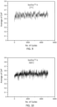
- FIGs. 9-14 show the average value of the coefficient of friction plotted against the number of cycles at room temperature (25°C) and 300°C for the CoCr alloy, SW, and SCW coatings on the stainless steel.
- the SW and SCW coatings showed a lower coefficient of friction than the CoCr alloy.
- the SCW coating showed a coefficient of friction behavior and values similar to the reference Stellite ® 6 CoCr alloy coating, whereas the SW coating showed a higher coefficient of friction. This is because WC particles are harder, and more abrasive compared to chromium carbide (Cr 3 C 2 ).
- the thermal softening of the metallic binder can cause the WC particles to protrude and create more asperities on the coating surface, resulting in a higher CoF.
- Table 5 shows the wear rate and wear volume values at room temperature and 300°C.
- the SW and SCW had lower wear rates than the reference HVOF Stellite ® 6 alloy. This is because the carbides offer a load bearing capacity to the coating modifying the contact area and distribution of the stresses, in addition of being more resistant to abrasion compared to the metallic matrix (Stellite ® 6 alloy).
- the 300°C wear rate and friction coefficient of SCW are higher than those of SW.
- SCW may have advantages at yet higher temperatures (e.g., in the range of 550°C to 800°C) due to higher temperature stability of chromium carbide relative to tungsten carbide.
- the addition of WC-Ni is believed to increase the hardness of the resultant coating to improve abrasive wear resistance.
- the parameters are believed to transfer to nickel-based superalloy substrates and cobalt-based superalloy substrates in applications such as described above and below.
- the two coatings were produced to achieve low wear rate values (WR ⁇ 10 -6 mm 3 /Nm) of the coating as well as the counterface at room temperature and high temperature (300°C) during reciprocating sliding.
- Low wear values can translate into increasing the lifecycle of materials during operation, particularly between room temperature and 300°C or more at relatively low loads (e.g., 5N).
- An example seal substrate is a nickel-based superalloy such as IN 718 (e.g., equiaxed).
- An example counterface is a nickel-based superalloy such as IN 718 (e.g., equiaxed).
- Such superalloy may be essentially uncoated (no added coating), but may form an alumina scale in service.
- the composite coatings may be put into service without any post-treatment. This is distinguished from Aoh (2001) and Tan, (2016) wherein there is a post-coating heat treatment involving annealing and aging. J.N. Aoh and J.C. Chen, “On the Wear Characteristics of Cobalt-based Hard-facing Layer after Thermal Fatigue and Oxidation", Wear, October 2001, Vol 250 (1-12), pp. 611-620, Elsevier Science B.V., Amsterdam, Netherlands ; J. Tan et al., "High performance Co-Cr3C2 composite coating by jet electrodeposition", Surface Engineering, December 2018, Vol. 34:11, pp. 861-869, Taylor & Francis Group, London, Engl and.
- HVOF allows forming high-density coatings and low decomposition of the carbides (due to melting or decarburization as in APS).
- high velocity air-fuel (HVAF) and cold spray are candidates.
- HVOF generally has higher operating temperature and lower particle velocity than HVAF and cold spray.
- Cold spray generally has the lowest operating temperature and highest particle velocity.
- HVAF is generally intermediate in both parameters.
- FIG. 15 schematically illustrates a gas turbine engine 120.
- the example gas turbine engine 120 is a two - spool turbofan that generally includes a fan section 122, a compressor section 124, a combustor section 126, and a turbine section 128.
- the fan section 122 drives air along a bypass flow path B in a bypass duct defined within a housing 115, such as a fan case or nacelle.
- the fan section also initially drives air along a core flow path C for compression through the compressor section and communication into the combustor section 126 then expansion through the turbine section 128.
- FIG. 15 schematically illustrates a gas turbine engine 120.
- the example gas turbine engine 120 is a two - spool turbofan that generally includes a fan section 122, a compressor section 124, a combustor section 126, and a turbine section 128.
- the fan section 122 drives air along a bypass flow path B in a bypass duct defined within a housing 115, such as
- the example engine 120 generally includes a low speed spool 130 and a high speed spool 132 mounted for rotation about an engine central longitudinal axis A relative to an engine static structure 136 via several bearing systems 138. It should be understood that various bearing systems 138 at various locations may alternatively or additionally be provided, and the location of bearing systems 138 may be varied as appropriate to the application.
- the low speed spool 130 generally includes an inner shaft 140 that interconnects, a first (or low) pressure compressor 144 and a first (or low) pressure turbine 146.
- the inner shaft 140 is connected to the fan 142 through a speed change mechanism, which in the example gas turbine engine 120 is illustrated as a geared architecture 148, to drive a fan 142 at a lower speed than the low speed spool 130.
- the high speed spool 132 includes an outer shaft 150 that interconnects a second (or high) pressure compressor 152 and a second (or high) pressure turbine 154.
- a combustor 156 is between the high pressure compressor 152 and the high pressure turbine 154.
- a mid-turbine frame 157 of the engine static structure 136 may be arranged generally between the high pressure turbine 154 and the low pressure turbine 146.
- the mid-turbine frame 157 further supports one or more of the bearing systems 138 in the turbine section 128.
- the inner shaft 140 and the outer shaft 150 are concentric and rotate via bearing systems 138 about the engine central longitudinal axis A which is collinear with their longitudinal axes.
- the core airflow is compressed by the low pressure compressor 144 then the high pressure compressor 152, mixed and burned with fuel in the combustor 156, then expanded over the high pressure turbine 154 and low 146 pressure turbine.
- the example mid-turbine frame 157 includes airfoils 159 which are in the core airflow path C.
- the turbines 146, 154 rotationally drive the respective low speed spool 130 and high speed spool 132 in response to the expansion. It will be appreciated that each of the positions of the fan section 122, compressor section 124, combustor section 126, turbine section 128, and fan drive gear system 148 may be varied.
- gear system 48 may be located aft of the low pressure compressor, or aft of the combustor section 26 or even aft of turbine section 128, and fan 142 may be positioned forward or aft of the location of gear system 48
- FIG. 15A shows one example seal in the engine as a piston seal 160.
- the example seal 160 (and its metallic substrate) has an inner diameter (ID) surface 161, an outer diameter (OD) surface 162, and axial end surfaces 164 and 165.
- the seal follows a constant cross-sectional shape and forms a split ring with a shiplap or similar joint (not shown).
- the piston seal 160 is partially accommodated in a radially outwardly open groove 170 in an inner member and its OD surface is engaged to an inner diameter (ID) surface 171 of an outer member.
- the example inner member is a vane structure (e.g., circumferential vane array) of the mid turbine frame 157.
- the example outer member is a seal runner of the static structure 136.
- the example groove is formed by the interior surfaces 174, 175 of wall sections 172, 173 and a base surface 176.
- the example walls have OD rims and outboard axial faces opposite the respective faces 174, 175.
- the counterface members may be uncoated alloy at the interfaces (e.g., uncoated at the surfaces 171, 174, 175).
- the seal substrate surface at the seal OD and/or axial end faces (or the entire cross-sectional perimeter surface) may be coated as above.
- a spring compression static seal For example, as in the '122 publication baseline, stainless steel or nickel- or cobalt-based superalloy or other seal substrates may be formed by deforming sheetmetal or may be cast or otherwise formed.
- Example seals include axial compression seals such as a bellows seal or a W-seal, or for radial compression seals, such as C-seals or E-seals.
- seal 220 FIG. 15B
- seal 220 is a bellows or similar type seal with convoluted cross-section effective to be deformed under compression to self-spring-bias engagement with the counterface members.
- the cross-section generally has a generally inner diameter (ID) surface 221, a generally outer diameter (OD) surface 222 generally parallel and spaced apart from the ID surface by a material thickness Ts, and end surfaces 224 and 225.
- ID inner diameter
- OD outer diameter
- end surfaces 224 and 225 In an installed axially compressed state, axial ends 226, 227 of the seal are formed by portions of one of the surfaces 221, 222 (both 221 in the example).
- the illustrated seal is a W-seal although other configurations are possible (e.g., more or fewer cycles of the cross-sectional wave form) as are radial seals (e.g., an E-seal).
- forward counterface members engaging the axial end 226 are a radially extending end surface portions 230 of a circumferential array of blade outer air seals (BOAS) 232.
- BOAS ID surfaces closely surround tips of airfoils 240 of a stage of blades 242.
- aft counterface members engaging the axial end are a radially extending end surface portions 250 of the OD shrouds 254 of a circumferential array of vanes 252.
- Example vanes are in clusters with multiple airfoils 253 per cluster.
- Example PSR (or other seal) substrate material is nickel- or cobalt-based superalloy (e.g., wrought).
- nickel-based superalloy legacy alloys are IN-718 (UNS N07718/W.Nr. 2.4668, Inconel ® alloy 718 Huntington Alloys Corp., Huntington WV), X750 (UNS N07750/W. Nr. 2.4669, Inconel ® alloy X750 Huntington Alloys Corp., Huntington WV), and Waspaloy (alloy 685, N07001).
- new alloys are continually being proposed.
- Each example counterface member may be formed of a nickel- or cobalt-based based alloy or superalloy alloy (e.g., uncoated).
- Example nickel-based superalloys are Inconel ® 718 (IN-718; UNS N07718; AMS 5662), Inconel ® 100 (IN-100; UNS N13100; AMS 5397), and Inconel ® 713C (IN-713C; Alloy 713C), each of (Huntington Alloys Corp., Huntington WV) and Mar-M247.
- An example cobalt-based superalloy is Haynes ® 188 (UNS R30188) of Haynes International, Kokomo, Indiana.
- the seal substrate surface at least at the axial ends 226, 227 (forming contact surfaces) may be coated as above.
- new alloys are continually being proposed.
- the areas to be coated may be other than axial ends (e.g., shifted along the surface 221).
- Additional seal applications include brush seal systems, namely coating the brush seal counterface (e.g., runner). Typical brush seals have radially inwardly extending bristles engaging the OD surface of the counterface.
- US Patent No. 6170831B1 (the '831 patent), of Bouchard, January 9, 2001 , and entitled "Axial Brush Seal for Gas Turbine Engines” discloses a double-ended axial static brush seal system partially re-presented as 400 in FIG. 15C .
- the brush 402 has two protruding bristle sections 406, 407 (e.g., of a single cluster of bristles) engaging respective counterfaces (a case segment and a blade outer air seal segment).
- FIG. 15C shows the coating may be applied by the present methods to the counterface surface 408, 409 of the counterface substrate 410, 411 to engage the bristles.
- a typical locating pin 420 ( FIG. 16 ) has, forming opposite axial end sections of the pin, a base section or shank 422 for press-fit or threading into a hole or socket 428 in a first component 426 and a head 424 for accommodation in a hole or socket 432 of a second component 430.
- a flange 434 (if present) may separate the base or shank from the head.
- the head will typically have a tapered portion for guidance into the receiving socket 432.
- the OD surface of the press-in base or shank may be coated by the present methods. Additionally, the head and flange faces may be coated. With a threaded pin, it is more likely that only the flange and head may be coated and not the threaded shank.
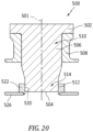
- FIG. 20 shows an alternate locating pin joint having a locating pin 500.
- FIG. 20 shows the joint and pin as having a common axis 501.
- Forming a first/proximal end of the pin in this example is a head or terminal flange 502.
- a shaft generally extends from an underside of the head to a distal end 504.
- a proximal portion 506 of the shaft mounts to a first component 508.
- An example first component is an engine case.
- An example mounting is via press-fit or threading into a boss of the case either directly or to an insert in the boss.
- the shaft exterior surface 512 along a proximal portion 510 of the shaft is so externally threaded to mate with an internal thread of the case boss or insert.
- the shaft exterior surface 512 is in sliding engagement with a second component.
- An example engagement is with the inner diameter surface 520 of a boss 522 of the second component acting as a socket for said pin distal end portion.
- the second component is an annular combustion chamber liner 526 held spaced apart from the case (e.g., radially inward).
- the boss may be separately formed from and welded to a main section of the liner.
- Example wearing movement is between the OD surface 512 and ID surface 520. Relative movement is parallel to the axis 501 and typically results from differential thermal expansion and engine vibration. Thus, one or both of these surfaces (surface 512 along the distal portion and surface 520) may be coated via the present methods.
- FIG. 17 Another snap example is a separate snap fastener 440 ( FIG. 17 ) (e.g., holding two (or more) generally flat sections (pieces) of material 442 and 444 against each other as if a rivet).
- the fastener has a head 446 with an underside 448 against the outer face 443 of one terminal piece 442 of the stack of mated pieces.
- a shaft or shank 450 extends from the underside to a tip/end 452. Adjacent the tip, the shaft has a barbed backlocking surface 454 (underside) facing the head and backlocked against the outer face 445 of the opposite terminal piece 444 in a sandwich of two or more pieces.
- Example fasteners have longitudinally split areas near the tip allowing insertion through holes in the pieces with the insertion compressing the slot 456 to allow passage of the barbs 458 and then relaxing once the barbs pass out of engagement with the members so as to back lock surfaces 454 to 445. Due to the relatively higher engagement pressures along the barb undersides 454 versus the head underside, the barb underside region and transition to shank main body 456 is a particular area for coating. With the snap fastener, the shaft/shank main body may also be coated by the present methods to limit wear of the holes in the mated components.
- snap fit interfaces 460 ( FIG. 15D ) (e.g., either fully backlocked or detented).
- FIG. 15D One example of a snap fit between two components involving a bead and groove interaction for mounting a swirler is shown in US Patent No. 10101031B2 (the '031 patent), of Williams et al., October 16, 2018 , and entitled "Swirler Mount Interface for Gas Turbine Engine Combustor”.
- the '031 patent discloses an OD (relative to swirler/injector axis 470) projection or bead 464 on a swirler 462 captured in an ID groove 468 in a bulkhead support shell 466.
- the coating may be applied by the present methods to one or both of the inner member (e.g., swirler) and outer member (e.g., bulkhead support shell) at the bead or groove and adjacent contacting OD and ID surface regions respectively.
- inner member e.g., swirler
- outer member e.g., bulkhead support shell
- ease of spraying may make it easiest to just apply to the OD surface of the inner member.
- tabs 481 ( FIGs. 18 &19) of a first component 480 in slots 483 in a second component 482
- tabs may protrude radially (inward or outward depending on the situation) and be received in associated slots.
- Example such tabs have first and second axial end faces 484, 485 facing or contacting slot end faces 486 and 487 and tab circumferential end faces (ends) 488, 489 contacting or facing slot circumferential end faces (ends) 490, 491.
- pressure or spring loading will bias one axially facing face 484 of the tab against the adjacent axially facing face 486 of the slot.
- axial end face of the tab may be coated via the present methods.
- circumferential end faces will typically provide some locating function and may also be coated. Spray access makes it easier to coat the tab faces (with a normal angle of incidence than coating slot faces (where the angle will be more off normal).
- Additional seal applications include examples involve knife edge seals (not shown).
- a typical knife edge seal has hardened knife edges.
- the runner usually an OD surface of an inner member but optionally an ID surface of an outer member
- An example knife edge seal is shown in US Patent No. 10167729B2 (the '729 patent), of Aiello et al., January 1, 2019 , and entitled "Knife Edge with Increased Crack Propagation Life".
- finger seals e.g., of steel or other alloys discussed above.
- the contacting portions of the seals themselves and/or the counterface surface may be coated via the present methods.
- Example finger seals are shown in US Patent No. 10094389B2 (the '389 patent), of Chuong et al., October 9, 2018 , and entitled “Flow Diverter to Redirect Secondary Flow", and US Patent No. 9845695B2 (the '695 patent), of Budnick et al., December 19, 2017 , and entitled “Gas Turbine Seal Assembly and Seal Support”.
- first, second, and the like in the following claims is for differentiation within the claim only and does not necessarily indicate relative or absolute importance or temporal order. Similarly, the identification in a claim of one element as “first” (or the like) does not preclude such "first” element from identifying an element that is referred to as “second” (or the like) in another claim or in the description.
Landscapes
- Chemical & Material Sciences (AREA)
- Engineering & Computer Science (AREA)
- Materials Engineering (AREA)
- Mechanical Engineering (AREA)
- Metallurgy (AREA)
- Organic Chemistry (AREA)
- Chemical Kinetics & Catalysis (AREA)
- Physics & Mathematics (AREA)
- Plasma & Fusion (AREA)
- Coating By Spraying Or Casting (AREA)
Abstract
A method for applying a coating (26), includes: providing a mixture of powders of comprising by volume percent: 10.0 to 60.0 one or more cobalt-based alloys (34) and 5.0 to 70.0 WC-Ni (32); and spraying the mixture on a metallic substrate (22). Each of the cobalt-based alloys (34) have by weight percent: Co as a largest constituent; 20.0-35.0 Cr; up to 3.0 C, if any; and up to 4.0 Ni, if any.
Description
- The disclosure relates to gas turbine engines. More particularly, the disclosure relates to coatings for hot section piston seal rings (PSR).
- Gas turbine engines (used in propulsion and power applications and broadly inclusive of turbojets, turboprops, turbofans, turboshafts, industrial gas turbines, and the like) use piston seal rings (PSR) in a variety of locations.
- Coatings produced by different thermal spray techniques are being used in a wide variety of applications. They can perform different functions such as thermal barriers, abradable, corrosion and wear resistant and, for each application, different strategies and choices of materials can be used to achieve the different properties desired for the target application. When high temperature conditions are involved, the protection against wear and corrosion in elevated temperatures becomes a main engineering challenge, because oxidation and the attack by corrosive elements combined with friction and mechanical wear can damage the materials exposed to those conditions, leading to premature failure of engineered parts.
- Currently, superalloy (e.g., IN718) static seals are commonly used uncoated in turbine engine hot sections and may be subject to damage by hot corrosion. Effects of hot corrosion often are reflected in weight/mass gain. Bare superalloys may have a weight gain up to 25mg/cm2 when exposed to hot corrosion conditions such as 0.5mg/cm2 of Na2SO4 at 900°C for 24 hours. Such high weight gain means that the alloy is being attacked by sulfur, which could lead to premature failure of the seal and mating counterface component. Furthermore, these parts are also exposed to severe tribological conditions, which means they suffer premature wear during high temperature operation.
- The use of commercially available self-lubricating coatings can increase the lifetime of these parts by improving tribological performance. However, these self-lubricating coatings (such as the NASA-developed PS304 and PS400) have shown poor resistance to hot corrosion conditions. PS304 is disclosed in
US Patent 5866518 of DellaCorte et al., entitled "Self-Lubricating Composite Chromium Oxide", issued February 2, 1999 . PS304 generally has NiCr binder with Cr2O3 hardener and Ag+ fluorides solid lubricant. PS400 is disclosed inUS Patent 8753417 of DellaCorte et al., entitled "High Temperature Solid Lubricant Coating for High Temperature Wear Applications", issued June 17, 2014 .PS400 generally has NiMoAl binder with Cr2O3 hardener and Ag+ fluorides solid lubricant. - A more recent proposal for a coating for such a PSR is found in
US Patent Application Publication 2021/0270369A1 of Stoyanov et al., entitled "Wear Resistant Self-Lubricating Static Seal", published January 6, 2022 . Another is found inUS Patent Application Publication No. 2022/0325797A1 (the '797 publication), of Stoyanov et al., entitled "Low Friction, Wear Resistant Piston Seal", published October 13, 2022 . The '797 publication discloses a coating with a CoCr alloy binder phase and a hard particle phase comprising Cr2O3. Application is via HVOF. - Composite coatings have been used on Fe alloy (e.g., carbon steel, stainless steel, Invar alloy) substrates for low and intermediate temperature ranges (e.g., room temperature up to about 500°C). In such coatings, cobalt and nickel are binder metals for WC and Cr3C2 (e.g., WC-Co, WC-CoCr, Cr3C2-NiCr, or Cr3C2-WC-NiCoCr).
- Another seal configuration is the W-seal of which an example is found in
US Patent Application Publication 2022/0065122A1 (the ' 122 publication) of Stoyanov et al., entitled "Seals and Methods of Making Seals", published March 3, 2022 . The '122 publication discloses both PSR and self-sprung compression seals. The self-sprung compression seals have cross-sections characterized by one or more cycles of a C-shape or W-shape. With such seals, sometimes because of seal orientation a different letter may be used (e.g., the letter E may be used to designate a radially compressed seal; whereas, the letter W may be used to designate an axially-compressed seal of similar cross-section but oriented 90° opposite). The '122 publication discloses both baseline seals made of conventional alloys (e.g., nickel-based superalloys) and modified seals made of HEA. - Depending on the production process, additional heat treatments or surface processing are needed to improve the mechanical properties. For example, annealing.
- One aspect of the disclosure involves a method for applying a coating. The method comprises: providing a mixture of powders comprising by volume percent: 10.0 to 60.0 one or more cobalt-based alloys, and 5.0 to 70.0 WC-Ni; and spraying the mixture on a metallic substrate. Each of the cobalt-based alloys have by weight percent: Co as a largest constituent; 20.0-35.0 Cr; up to 3.0 C, if any; and up to 4.0 Ni, if any.
- In a further example of any of the foregoing, additionally and/or alternatively, the mixture of powders comprises by volume percent: 12.0 to 55.0 said one or more cobalt-based alloys; and 10.0 to 65.0 said WC-Ni.
- In a further example of any of the foregoing, additionally and/or alternatively, the mixture of powders further has by volume percent 5.0 to 85.0 Cr3C2.
- In a further example of any of the foregoing, additionally and/or alternatively, the mixture of powders comprises by volume percent: 10.0 to 30.0 said one or more cobalt-based alloys; 8.0 to 30.0 said WC-Ni; and 50.0 to 80.0 said Cr3C2.
- In a further example of any of the foregoing, additionally and/or alternatively, the powder of WC-Ni is an agglomerated and sintered WC-Ni.
- In a further example of any of the foregoing, additionally and/or alternatively, the spraying is HVOF spraying or HVAF spraying or cold spray.
- In a further example of any of the foregoing, additionally and/or alternatively, the spraying is to a thickness of 75 micrometers to 130 micrometers.
- In a further example of any of the foregoing, additionally and/or alternatively, the one or more cobalt-based alloys each comprise by weight percent: Co as said largest constituent; 25.00 to 32.00 Cr; 0.9 to 2.0 C; 3.0 to 6.0 W; 1.0-4.0 Fe; up to 1.5 Mn, if any; 0.5 to 2.0 Si; up to 0.1 P, if any; up to 0.1 S, if any; up to 2.0 Mo, if any; and 1.0-4.0 Ni.
- In a further example of any of the foregoing, additionally and/or alternatively, the one or more cobalt-based alloys each comprise by weight percent: Co as said largest constituent; 28.00 to 32.00 Cr; 0.9 to 2.0 C; 3.0 to 6.0 W; up to 3.0 Fe, if any; 0.5 to 2.0 Mn; 0.2 to 2.0 Si; up to 0.04 P, if any; up to 0.03 S, if any; up to 1.50 Mo, if any; and up to 3.0 Ni, if any.
- In a further example of any of the foregoing, additionally and/or alternatively, the mixture of powders comprises by volume percent: 30.0 to 60.0 said one or more cobalt-based alloys; and 40.0 to 70.0 said WC-Ni.
- In a further example of any of the foregoing, additionally and/or alternatively, the mixture of powders comprises by volume percent: up to 20.0 Cr3C2, if any.
- In a further example of any of the foregoing, additionally and/or alternatively, the mixture of powders comprises by volume percent: up to 10.0 Cr3C2, if any.
- In a further example of any of the foregoing, additionally and/or alternatively, the mixture of powders comprises by volume percent: 10.0 to 30.0 said one or more cobalt-based alloys. 8.0 to 30.0 said WC-Ni; and 50.0 to 80.0 Cr3C2.
- In a further example of any of the foregoing, additionally and/or alternatively, the substrate is a split ring seal substrate and the spraying is at least to an outer diameter surface of the substrate.
- In a further example of any of the foregoing, additionally and/or alternatively, the substrate is a spring compression seal substrate and the spraying is at least to an outer an axial end surface portion of the substrate.
- In a further example of any of the foregoing, additionally and/or alternatively, the substrate is a HALO seal substrate and the spraying is to an inner diameter surface of the substrate.
- In a further example of any of the foregoing, additionally and/or alternatively, the substrate is a locating pin substrate and the spraying is to a base of the locating pin or a distal end section of the locating pin.
- In a further example of any of the foregoing, additionally and/or alternatively, the substrate interfaces with a locating pin and the spraying is to a counterface surface for the locating pin.
- In a further example of any of the foregoing, additionally and/or alternatively, the substrate is a snap fastener substrate and the spraying is to a shaft and a barb underside.
- In a further example of any of the foregoing, additionally and/or alternatively, the substrate is of a component having a snap fit bead or groove and the spraying is to said bead or groove.
- In a further example of any of the foregoing, additionally and/or alternatively, the substrate is of a component having a tab and the spraying is to a face of the tab.
- In a further example of any of the foregoing, additionally and/or alternatively, the substrate is of a component having seal counterface and the spraying is to the seal counterface.
- In a further example of any of the foregoing, additionally and/or alternatively, the substrate is a seal substrate and the coating is to a contact surface portion of the substrate.
- A further aspect of the disclosure involves an article comprising: a metallic substrate; and a coating on the metallic substrate; wherein the coating comprises by volume percent: 18.0 to 50.0 an alloy having, by weight percent, Co as a largest constituent and 20.0-35.0 Cr; and 11.0 to 70.0 WC-Ni.
- In a further example of any of the foregoing, additionally and/or alternatively, the coating further comprises by volume percent: up to 65% Cr3C2, if any and wherein at last 95% by volume exclusive of porosity is said alloy, said WC-Ni, and said Cr3C2, if any.
- In a further example of any of the foregoing, additionally and/or alternatively, the coating has a thickness of 50 micrometers to 200 micrometers.
- In a further example of any of the foregoing, additionally and/or alternatively, the substrate forms a split ring; and the coating is on an outer diameter surface of the substrate.
- In a further example of any of the foregoing, additionally and/or alternatively, the substrate is a nickel-based superalloy or cobalt-based superalloy.
- In a further example of any of the foregoing, additionally and/or alternatively: a counterface is in sliding engagement with the coating and comprising a nickel-based superalloy substrate.
- In a further example of any of the foregoing, additionally and/or alternatively: the substrate is a split ring seal substrate and the spraying is at least to an outer diameter surface of the substrate; or the substrate is a spring compression seal substrate and the spraying is at least to an outer an axial end surface portion of the substrate; the substrate is a HALO seal substrate and the spraying is to an inner diameter surface of the substrate; or the substrate is a locating pin substrate and the spraying is to a base of the locating pin or a distal end section of the locating pin; or the substrate interfaces with a locating pin and the spraying is to a counterface surface for the locating pin; or the substrate is a snap fastener substrate and the spraying is to a shaft and a barb underside; or the substrate is of a component having a snap fit bead or groove and the spraying is to said bead or groove; or the substrate is of a component having a tab and the spraying is to a face of the tab; or the substrate is of a component having a seal counterface and the spraying is to the seal counterface.
- The details of one or more embodiments are set forth in the accompanying drawings and the description below. Other features, objects, and advantages will be apparent from the description and drawings, and from the claims.
-
-
FIG. 1 is a micrograph of a substrate coated with a CoCr alloy/WC-Ni coating. -
FIG. 2 is a micrograph of a substrate coated with a CoCr alloy/Cr3C2/WC-Ni coating. -
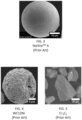
FIG. 3 is a photograph of a CoCr alloy powder particle. -
FIG. 4 is a photograph of a WC-Ni particle. -
FIG. 5 is a photograph of Cr3C2 particles. -
FIG. 6 is a plot of particle diameter for the CoCr alloy powder feedstock. -
FIG. 7 is a particle size distribution plot for the WC-Ni powder feedstock. -
FIG. 8 is a particle size distribution plot for the Cr3C2 powder feedstock. -
FIG. 9 is a friction coefficient plot for CoCr alloy at room temperature. -
FIG. 10 is a friction coefficient plot for CoCr alloy at 300°C. -
FIG. 11 is a plot of the CoCr alloy/WC-Ni coating at room temperature. -
FIG. 12 is a plot of CoCr alloy/WC-Ni coating at 300°C. -
FIG. 13 is a plot of the CoCr alloy/Cr3C2/WC-Ni coating at room temperature. -
FIG. 14 is a plot of CoCr alloy/Cr3C2/WC-Ni coating at 300°C. -
FIG. 15 is a view of a gas turbine engine. -
FIG. 15A is an enlarged view of a first seal system in the engine ofFIG. 15 . -
FIG. 15B is an enlarged view of a second seal system in the engine ofFIG. 15 . -
FIG. 15C is an enlarged view of a third seal system in the engine ofFIG. 10 . -
FIG. 15D is an enlarged view combustor swirler in the engine ofFIG. 10 . -
FIG. 16 is a longitudinal sectional/cutaway view of a locating pin joint. -
FIG. 17 is a longitudinal sectional view of a snap fastener joint. -
FIG. 18 is an inward radial view of a mounting tab-in-slot joint. -
FIG. 19 is a longitudinal sectional view of the joint ofFIG. 18 . -
FIG. 20 is a longitudinal sectional view of an alternate locating pin joint. - Like reference numbers and designations in the various drawings indicate like elements.
- To help improve the endurance life of next generation mechanical systems in gas turbine engines, cobalt-based alloy composite coatings with the addition of WC-Ni or Cr3C2 and WC-Ni were produced to reach low wear rate values (WR<10-6 mm3/Nm) of the coating as well as the counterface at room temperature and elevated temperature (300°C) during reciprocating/fretting wear. Particular tests were conducted on coatings that, for the CoCr alloy feedstock used Stellite® 6 gas atomized alloy of Kennametal Inc., Latrobe Pennsylvania.
-
FIGs. 1 and 2 respectively showarticles coating 26 and Stellite® 6 alloy/ Cr3C2/WC-Ni (designated SCW) coating 27 HVOF sprayed on asurface 24 of asubstrate 22. The example substrate is stainless steel. The substrate may form a seal and thecoating surface 28 surface may be the tribological interface of the seal (examples discussed below and discussion in the ` 122 publication). Thecoatings - The
FIGs. 1 &2 coatings are formed by: molten and semi-molten splats (which quickly solidify) of the CoCr alloy and deformed carbides. No dendrite or spike-like structure was observed. Rather, carbides and the CoCr alloy splats were homogeneously distributed across the coating with no segregation or agglomeration of a specific phase. In the images: WC-Ni (brightest - light grey) 32; CoCr alloy (medium grey) 34; and Cr3C2 (dark grey) 36. - In
FIG. 1 , it is seen that splats of both phases, CoCr alloy and WC-Ni, are homogeneously distributed throughout the coating. - In
FIG.2 , it is seen that splats of the different phases, CoCr alloy, WC-Ni, and Cr3C2, are homogeneously distributed throughout the coating. - The coatings tested were produced with a mixture of powders: gas-atomized Co-Cr alloy (Stellite® 6 CoCr alloy of Kennametal Inc., Latrobe PA) (
FIG. 3 ); fused-crushed Cr3C2 (FIG. 5 ); and agglomerated and sintered WC-Ni (AMPERIT® 547 of Höganäs AB, Höganäs, Sweden, nominal WC12N1, particle size: 45/15 µm) (FIG. 4 ). The powder particle size distribution is similar for the three powders, as shown inFIGs 6, 7 (WC-Ni), and 8 (Cr3C2). As a reference, D50 of the different powders are 34µm (Stellite® 6 CoCr alloy), 37µm (WC-Ni), and 37µm (Cr3C2), respectively. The WC-Ni size is of the sintered agglomerate, not the particles forming the agglomerate particles (the latter being about 1µm). - Table 1 below shows example Co-Cr alloy compositions. Table 2 shows two example tested powder blends that used Stellite® 6 CoCr alloy as the Co-Cr alloy and alternative example ranges.
Table 1 Co-Cr alloy Composition (Weight %) Alloy C Mn Si P S Cr Ni Co Mo W Fe Other Cobalt Alloy 6 nom range 1-2 1-2 27-32 3-4 bal 4-6 3-4 Cobalt Alloy 6b AMS 5894 (wrought) 0.90-1.40 0.50-2.00 0.20-2.00 0.04 max 0.03 max 28.00-32.00 3.00 max bal 1.50 max 3.50-5.50 3.0 max Cobalt Alloy 6b nom. (wrought) 1.15 1.25 1.10 30 bal 4.5 Cobalt Alloy 6k (wrought) 1.40-1.90 0.50-2.00 0.20-2.00 0.04 max 0.03 max 28.00-32.00 3.00 max bal 1.50 max 3.50-5.50 3.0 max Tested alloy vendor spec. 0.9-1.4 0.5 max 0.7-1.5 0.030 max 0.030 max 27.0-30.0 3.0 max bal 1.0 max 3.5-5.5 3.0 max 0.5 max total Tested alloy sample assay 1.2 0.5 1.3 0.003 0.003 28.0 2.1 bal 0.2 4.8 2.1 0.06N2; 0.02O2 Range 1 2.0 max 2.5 max 2.5 max 0.1 max 0.1 max 27.0-32.0 4.0 max bal 2.0 max 6.0 max 4.0 max †† Range 2 2.0 max 2.5 max 2.5 max 0.1 max 0.1 max 27.0-32.0 4.0 max bal 2.0 max 3.00-6.00 4.0 max †† Range 3 0.90-2.00 0.50-2.00 0.20-2.00 0.04 max 0.03 max 28.00-32.00 3.00 max bal 1.50 max 3.00-6.00 3.0 max ttt Range 4 0.90-1.90 0.50-2.00 0.20-2.00 0.04 max 0.03 max 28.00-32.00 3.00 max bal 1.50 max 3.50-5.50 3.0 max ttt Range 5 0.90-1.90 0.50-2.00 0.20-2.00 0.04 max 0.03 max 25.00-35.00 3.00 max bal 1.50 max 3.50-5.50 3.0 max ttt Range 6 0.90-1.40 0.50-2.00 0.20-2.00 0.04 max 0.03 max 28.00-32.00 3.00 max bal 1.50 max 3.50-5.50 3.0 max ttt Range 7 0.90-1.40 0.50-2.00 0.20-200 0.04 max 0.03 max 25.00-35.00 3.00 max bal 1.50 max 3.50-5.50 3.0 max ttt Range 8 2.0 max 2.5 max 2.5 max 0.1 max 0.1 max 20.0-35.0 4.0 max bal 2.0 max 6.0 max 4.0 max ttt Range 9 0.5-2.0 2.5 max 2.5 max 0.1 max 0.1 max 25.0-35.0 4.0 max bal 2.0 max 6.0 max 4.0 max ttt Range 10 0.9-2.0 1.5 max 2.0 max 0.1 max 0.1 max 25.0-35.0 4.0 max bal 2.0 max 6.0 max 4.0 max ttt Range 11 0.9-2.0 1.5 max 0.5-2.0 0.1 max 0.1 max 25.0-32.0 1.0-4.0 bal 2.0 max 3.0-6.0 1.0-4.0 ttt † ≤ 15.0 Other total; ≤ 7.0 other individually
†† ≤ 5.0 Other total; ≤ 1.0 other individually
††† ≤ 2.0 Other total; ≤ 0.50 other individually - The first four rows are taken from different industry sources. The powders were mixed according to the ratio shown in Table 2 (which ignores voids in the mixture) and were deposited by high-velocity oxygen-fuel (HVOF) spray using the spraying parameters in Table 3 to a thickness of
coating 26 of 248 ± 12 micrometers andcoating 27 of 230 ± 40 micrometers. The substrate was stainless steel. The coating containing the CoCr alloy and WC-Ni is identified as "SW" and the coating containing the CoCr alloy in addition to WC-Ni and Cr3C2 is identified as "SCW".Table 2 Tested Coating Feed Powder Composition Coating Powder mixture (vol%) Co-Cr Alloy Cr3C2 WC-Ni SW Bal. - 55 SCW Bal. 70 10 Range 1A 10.0-60.0 ≤ 85.0 5.0-70.0 Range 1B 12.0-55.0 ≤ 78.0 10.0-65.0 Range 1C 12.0-55.0 ≤ 78.0 8.0-65.0 Range 2A 30.0-60.0 ≤ 20.0 40.0-70.0 Range 2B 30.0-50.0 ≤ 10.0 50.0-70.0 Range 2C 30.0-50.0 ≤ 5.0 50.0-65.0 Range 3A 10.0-30.0 50.0-80.0 8.0-30.0 Range 3B 10.0-30.0 60.0-80.0 10.0-25.0 Range 4A 10.0-60.0 5.0-85.0 5.0-70.0 Range 4B 12.0-55.0 5.0-85.0 10.0-65.0 - As additional variations, optionally any of these ranges may include impurity levels of other elements, compounds, and the like, In further examples these other materials may represent up to 5.0 volume percent aggregate and up to 2.0 or 1.0 volume percent individually. In yet other examples, additions include pre-formed lubricious oxides. For example, cobalt oxides and tungsten oxides may be included initially so that one does not have to wait for in-service oxidation of cobalt and tungsten. These may be included in said small aggregate amounts but possibly above the individual.
Table 3. HVOF spraying parameters Parameter Powder Feed Rate (g/min) Oxygen Flow rate (LPM) Propylene flow rate (LPM) Air flow rate (LPM) Spraying distance (mm) Value 23 304 79 422 150 - The spraying was by using a Diamond Jet™ 2700 gun of Oerlikon Metco, Pfaeffikon, Switzerland.
- Table 4 shows: deposition efficiency (DE); volume fraction of matrix, carbide, and porosity; and Vickers hardness. Retention of Cr3C2 in the coating is lower than WC-Ni, decreasing the DE of SCW compared to SW. Vickers hardness was tested at room (RT) and elevated temperature (300°C). Hardness values are higher for the SCW coating at both RT and HT. Table 5 shows wear rate measured as V/(FN×L) where V is the wear volume (mm3), FN is the applied load (N) and L represents the length (m).
Table 4 Hardness of as-Sprayed (pre-use and without Heat Treat) Coatings and Example Composition Ranges Coating DE (%) Percentage in Coating (vol%) Hardness (HV0.3) CoCr alloy Cr3C2 WC-Ni Porosity RT 300°C SW 75 37 ± 4 - 61 ± 4 3 ± 0.3 800 ± 123 693 ± 96 SCW 40 24 ± 2 58 ± 2 17 ± 1 1 ± 0.7 918 ± 114 820 ± 64 Range 1A NA 18.0-50.0 ≤ 70.0 11.0-70.0 ≤ 8.0 NA NA Range 1B NA 19.0-45.0 ≤ 65.0 15.0-70.0 ≤ 8.0 NA NA Range 2A NA 25.0-50.0 ≤ 20.0 35.0-70.0 ≤ 8.0 NA NA Range 2B NA 30.0-50.0 ≤ 10.0 40.0-70.0 ≤ 8.0 NA NA Range 3A NA 18.0-40.0 45.0-70.0 11.0-30.0 ≤ 8.0 NA NA Range 3B NA 19.0-30.0 45.0-65.0 15.0-25.0 ≤ 8.0 NA NA Table 5 Wear Rate of as-Spraved (pre-use and without Heat Treat) Coatings Coating Temperature (°C) Average of Wear volume (×10-3 mm3) Average of Wear rate (×10-6 mm3/N.m) Stellite® 6 CoCr alloy RT 34.96 ± 2.86 69.93 ± 5.7 300 86.64 ± 6.99 173.27 ± 14 SW RT 0.81 ± 0.23 1.61 ± 0.45 300 1.23 ± 0.23 2.46 ± 0.46 SCW RT 1.16 ± 0.47 2.32 ± 0.94 300 17.56 ± 2.97 35.13 ± 5.9 - The Table 5 wear tests were conducted in a ball-on-flat configuration in reciprocating motion at room temperature and elevated temperature (300°C) on an alumina (Al2O3) counterface with the three identified coatings on stainless steel substrates.
-
FIGs. 9-14 show the average value of the coefficient of friction plotted against the number of cycles at room temperature (25°C) and 300°C for the CoCr alloy, SW, and SCW coatings on the stainless steel. At room temperature, the SW and SCW coatings showed a lower coefficient of friction than the CoCr alloy. At 300°C, the SCW coating showed a coefficient of friction behavior and values similar to the reference Stellite® 6 CoCr alloy coating, whereas the SW coating showed a higher coefficient of friction. This is because WC particles are harder, and more abrasive compared to chromium carbide (Cr3C2). Additionally, the thermal softening of the metallic binder (the CoCr alloy) can cause the WC particles to protrude and create more asperities on the coating surface, resulting in a higher CoF. Table 5 shows the wear rate and wear volume values at room temperature and 300°C. The SW and SCW had lower wear rates than the reference HVOF Stellite® 6 alloy. This is because the carbides offer a load bearing capacity to the coating modifying the contact area and distribution of the stresses, in addition of being more resistant to abrasion compared to the metallic matrix (Stellite® 6 alloy). The 300°C wear rate and friction coefficient of SCW are higher than those of SW. However, SCW may have advantages at yet higher temperatures (e.g., in the range of 550°C to 800°C) due to higher temperature stability of chromium carbide relative to tungsten carbide. Relative to the '797 publication, the addition of WC-Ni is believed to increase the hardness of the resultant coating to improve abrasive wear resistance. Despite testing the present parameters only on steel, the parameters are believed to transfer to nickel-based superalloy substrates and cobalt-based superalloy substrates in applications such as described above and below. - As mentioned above, the two coatings were produced to achieve low wear rate values (WR<10-6 mm3/Nm) of the coating as well as the counterface at room temperature and high temperature (300°C) during reciprocating sliding. Low wear values can translate into increasing the lifecycle of materials during operation, particularly between room temperature and 300°C or more at relatively low loads (e.g., 5N). An example seal substrate is a nickel-based superalloy such as IN 718 (e.g., equiaxed). An example counterface is a nickel-based superalloy such as IN 718 (e.g., equiaxed). Such superalloy may be essentially uncoated (no added coating), but may form an alumina scale in service.
- The composite coatings may be put into service without any post-treatment. This is distinguished from Aoh (2001) and Tan, (2018) wherein there is a post-coating heat treatment involving annealing and aging. J.N. Aoh and J.C. Chen, "On the Wear Characteristics of Cobalt-based Hard-facing Layer after Thermal Fatigue and Oxidation", Wear, October 2001, Vol 250 (1-12), pp. 611-620, Elsevier Science B.V., Amsterdam, Netherlands; J. Tan et al., "High performance Co-Cr3C2 composite coating by jet electrodeposition", Surface Engineering, December 2018, Vol. 34:11, pp. 861-869, Taylor & Francis Group, London, England.
- HVOF allows forming high-density coatings and low decomposition of the carbides (due to melting or decarburization as in APS). The combination of the production process (HVOF) and the ratio of the metallic matrix (Stellite™ 6) to carbides showed good wear resistance (low wear rate). Additionally, high velocity air-fuel (HVAF) and cold spray are candidates. Of these three non-plasma techniques, HVOF generally has higher operating temperature and lower particle velocity than HVAF and cold spray. Cold spray generally has the lowest operating temperature and highest particle velocity. HVAF is generally intermediate in both parameters.
-
FIG. 15 schematically illustrates agas turbine engine 120. The examplegas turbine engine 120 is a two - spool turbofan that generally includes afan section 122, acompressor section 124, acombustor section 126, and aturbine section 128. Thefan section 122 drives air along a bypass flow path B in a bypass duct defined within ahousing 115, such as a fan case or nacelle. The fan section also initially drives air along a core flow path C for compression through the compressor section and communication into thecombustor section 126 then expansion through theturbine section 128. Although depicted as a two-spool turbofan gas turbine engine in the disclosed non-limiting embodiment, it should be understood that the concepts described herein are not limited to use with two-spool turbofans as the teachings may be applied to other types of turbine engines. - The
example engine 120 generally includes alow speed spool 130 and ahigh speed spool 132 mounted for rotation about an engine central longitudinal axis A relative to an enginestatic structure 136 via several bearingsystems 138. It should be understood that various bearingsystems 138 at various locations may alternatively or additionally be provided, and the location of bearingsystems 138 may be varied as appropriate to the application. - The
low speed spool 130 generally includes aninner shaft 140 that interconnects, a first (or low)pressure compressor 144 and a first (or low)pressure turbine 146. Theinner shaft 140 is connected to thefan 142 through a speed change mechanism, which in the examplegas turbine engine 120 is illustrated as a gearedarchitecture 148, to drive afan 142 at a lower speed than thelow speed spool 130. Thehigh speed spool 132 includes anouter shaft 150 that interconnects a second (or high)pressure compressor 152 and a second (or high)pressure turbine 154. Acombustor 156 is between thehigh pressure compressor 152 and thehigh pressure turbine 154. Amid-turbine frame 157 of the enginestatic structure 136 may be arranged generally between thehigh pressure turbine 154 and thelow pressure turbine 146. Themid-turbine frame 157 further supports one or more of the bearingsystems 138 in theturbine section 128. Theinner shaft 140 and theouter shaft 150 are concentric and rotate via bearingsystems 138 about the engine central longitudinal axis A which is collinear with their longitudinal axes. - The core airflow is compressed by the
low pressure compressor 144 then thehigh pressure compressor 152, mixed and burned with fuel in thecombustor 156, then expanded over thehigh pressure turbine 154 and low 146 pressure turbine. Theexample mid-turbine frame 157 includesairfoils 159 which are in the core airflow path C. Theturbines low speed spool 130 andhigh speed spool 132 in response to the expansion. It will be appreciated that each of the positions of thefan section 122,compressor section 124,combustor section 126,turbine section 128, and fandrive gear system 148 may be varied. For example, gear system 48 may be located aft of the low pressure compressor, or aft of thecombustor section 26 or even aft ofturbine section 128, andfan 142 may be positioned forward or aft of the location of gear system 48
FIG. 15A shows one example seal in the engine as apiston seal 160. The example seal 160 (and its metallic substrate) has an inner diameter (ID)surface 161, an outer diameter (OD)surface 162, and axial end surfaces 164 and 165. The seal follows a constant cross-sectional shape and forms a split ring with a shiplap or similar joint (not shown). - In the illustrated example, the
piston seal 160 is partially accommodated in a radially outwardlyopen groove 170 in an inner member and its OD surface is engaged to an inner diameter (ID)surface 171 of an outer member. The example inner member is a vane structure (e.g., circumferential vane array) of themid turbine frame 157. The example outer member is a seal runner of thestatic structure 136. The example groove is formed by theinterior surfaces wall sections base surface 176. The example walls have OD rims and outboard axial faces opposite the respective faces 174, 175. - Principal contact between the seal and the contacting members is between the seal OD
surface 162 and therunner ID surface 171. Additional contact may be between the seal axial end surfaces and the adjacent groove wall surface. Wear and damage may occur at any of these. Typically, the counterface members may be uncoated alloy at the interfaces (e.g., uncoated at thesurfaces - Another example is a spring compression static seal. For example, as in the '122 publication baseline, stainless steel or nickel- or cobalt-based superalloy or other seal substrates may be formed by deforming sheetmetal or may be cast or otherwise formed. Example seals include axial compression seals such as a bellows seal or a W-seal, or for radial compression seals, such as C-seals or E-seals. For example, seal 220 (
FIG. 15B ) is a bellows or similar type seal with convoluted cross-section effective to be deformed under compression to self-spring-bias engagement with the counterface members. The cross-section generally has a generally inner diameter (ID)surface 221, a generally outer diameter (OD) surface 222 generally parallel and spaced apart from the ID surface by a material thickness Ts, and end surfaces 224 and 225. In an installed axially compressed state, axial ends 226, 227 of the seal are formed by portions of one of thesurfaces 221, 222 (both 221 in the example). The illustrated seal is a W-seal although other configurations are possible (e.g., more or fewer cycles of the cross-sectional wave form) as are radial seals (e.g., an E-seal). - For the example seal 220, forward counterface members engaging the
axial end 226 are a radially extendingend surface portions 230 of a circumferential array of blade outer air seals (BOAS) 232. BOAS ID surfaces closely surround tips ofairfoils 240 of a stage ofblades 242. For the example seal 220, aft counterface members engaging the axial end are a radially extendingend surface portions 250 of the OD shrouds 254 of a circumferential array ofvanes 252. Example vanes are in clusters withmultiple airfoils 253 per cluster. - In these example embodiments, wear may notably occur at counterface surfaces 171, 174, 175, 230, and 250. Example PSR (or other seal) substrate material is nickel- or cobalt-based superalloy (e.g., wrought). Example, nickel-based superalloy legacy alloys are IN-718 (UNS N07718/W.Nr. 2.4668, Inconel® alloy 718 Huntington Alloys Corp., Huntington WV), X750 (UNS N07750/W. Nr. 2.4669, Inconel® alloy X750 Huntington Alloys Corp., Huntington WV), and Waspaloy (alloy 685, N07001). However, new alloys are continually being proposed. Each example counterface member (or other member to be coated or not described above or below) may be formed of a nickel- or cobalt-based based alloy or superalloy alloy (e.g., uncoated). Example nickel-based superalloys are Inconel® 718 (IN-718; UNS N07718; AMS 5662), Inconel® 100 (IN-100; UNS N13100; AMS 5397), and Inconel® 713C (IN-713C; Alloy 713C), each of (Huntington Alloys Corp., Huntington WV) and Mar-M247. An example cobalt-based superalloy is Haynes® 188 (UNS R30188) of Haynes International, Kokomo, Indiana. Thus, the seal substrate surface at least at the axial ends 226, 227 (forming contact surfaces) (or the entire cross-sectional perimeter surface) may be coated as above. However, new alloys are continually being proposed. In the seal relaxed/extended pre-installation condition, the areas to be coated may be other than axial ends (e.g., shifted along the surface 221).
- Additional seal applications include brush seal systems, namely coating the brush seal counterface (e.g., runner). Typical brush seals have radially inwardly extending bristles engaging the OD surface of the counterface.
US Patent No. 6170831B1 (the '831 patent), of Bouchard, January 9, 2001 , and entitled "Axial Brush Seal for Gas Turbine Engines" discloses a double-ended axial static brush seal system partially re-presented as 400 inFIG. 15C . Thebrush 402 has two protruding bristlesections 406, 407 (e.g., of a single cluster of bristles) engaging respective counterfaces (a case segment and a blade outer air seal segment).FIG. 15C shows the coating may be applied by the present methods to thecounterface surface counterface substrate - Other examples involve locating pins. A typical locating pin 420 (
FIG. 16 ) has, forming opposite axial end sections of the pin, a base section orshank 422 for press-fit or threading into a hole orsocket 428 in afirst component 426 and ahead 424 for accommodation in a hole orsocket 432 of asecond component 430. A flange 434 (if present) may separate the base or shank from the head. The head will typically have a tapered portion for guidance into the receivingsocket 432. With a press-fit pin, the OD surface of the press-in base or shank may be coated by the present methods. Additionally, the head and flange faces may be coated. With a threaded pin, it is more likely that only the flange and head may be coated and not the threaded shank. -
FIG. 20 shows an alternate locating pin joint having a locatingpin 500.FIG. 20 shows the joint and pin as having acommon axis 501. Forming a first/proximal end of the pin in this example is a head orterminal flange 502. A shaft generally extends from an underside of the head to adistal end 504. Aproximal portion 506 of the shaft mounts to afirst component 508. An example first component is an engine case. An example mounting is via press-fit or threading into a boss of the case either directly or to an insert in the boss. In this example, theshaft exterior surface 512 along aproximal portion 510 of the shaft is so externally threaded to mate with an internal thread of the case boss or insert. - Along a
distal end portion 514 of the shaft, theshaft exterior surface 512 is in sliding engagement with a second component. An example engagement is with theinner diameter surface 520 of aboss 522 of the second component acting as a socket for said pin distal end portion. In the example, the second component is an annularcombustion chamber liner 526 held spaced apart from the case (e.g., radially inward). The boss may be separately formed from and welded to a main section of the liner. Example wearing movement is between theOD surface 512 andID surface 520. Relative movement is parallel to theaxis 501 and typically results from differential thermal expansion and engine vibration. Thus, one or both of these surfaces (surface 512 along the distal portion and surface 520) may be coated via the present methods. - Another snap example is a separate snap fastener 440 (
FIG. 17 ) (e.g., holding two (or more) generally flat sections (pieces) ofmaterial head 446 with anunderside 448 against theouter face 443 of oneterminal piece 442 of the stack of mated pieces. A shaft orshank 450 extends from the underside to a tip/end 452. Adjacent the tip, the shaft has a barbed backlocking surface 454 (underside) facing the head and backlocked against theouter face 445 of the oppositeterminal piece 444 in a sandwich of two or more pieces. Example fasteners have longitudinally split areas near the tip allowing insertion through holes in the pieces with the insertion compressing theslot 456 to allow passage of the barbs 458 and then relaxing once the barbs pass out of engagement with the members so as to back lock surfaces 454 to 445. Due to the relatively higher engagement pressures along thebarb undersides 454 versus the head underside, the barb underside region and transition to shankmain body 456 is a particular area for coating. With the snap fastener, the shaft/shank main body may also be coated by the present methods to limit wear of the holes in the mated components. - Among additional locations for the coating are in snap fit interfaces 460 (
FIG. 15D ) (e.g., either fully backlocked or detented). One example of a snap fit between two components involving a bead and groove interaction for mounting a swirler is shown inUS Patent No. 10101031B2 (the '031 patent), of Williams et al., October 16, 2018 bead 464 on aswirler 462 captured in anID groove 468 in abulkhead support shell 466. The coating may be applied by the present methods to one or both of the inner member (e.g., swirler) and outer member (e.g., bulkhead support shell) at the bead or groove and adjacent contacting OD and ID surface regions respectively. Often, ease of spraying may make it easiest to just apply to the OD surface of the inner member. But, with a large diameter and relatively small axial extent, it may be easy to also have normal spray access to the bulkhead ID surface to coat both pieces. - Additional examples involve tabs 481 (
FIGs. 18 &19) of afirst component 480 inslots 483 in asecond component 482 For example, in many annular mounting situations, tabs may protrude radially (inward or outward depending on the situation) and be received in associated slots. Example such tabs have first and second axial end faces 484, 485 facing or contacting slot end faces 486 and 487 and tab circumferential end faces (ends) 488, 489 contacting or facing slot circumferential end faces (ends) 490, 491. Typically, pressure or spring loading will bias one axially facingface 484 of the tab against the adjacentaxially facing face 486 of the slot. Particularly that axial end face of the tab may be coated via the present methods. But also, circumferential end faces will typically provide some locating function and may also be coated. Spray access makes it easier to coat the tab faces (with a normal angle of incidence than coating slot faces (where the angle will be more off normal). - Additional seal applications include examples involve knife edge seals (not shown). A typical knife edge seal has hardened knife edges. Thus, the runner (usually an OD surface of an inner member but optionally an ID surface of an outer member) may be the counterface coated by the present methods. An example knife edge seal is shown in
US Patent No. 10167729B2 (the '729 patent), of Aiello et al., January 1, 2019 - Additional seal applications involve finger seals (e.g., of steel or other alloys discussed above). With finger seals, the contacting portions of the seals themselves and/or the counterface surface may be coated via the present methods. Example finger seals are shown in
US Patent No. 10094389B2 (the '389 patent), of Chuong et al., October 9, 2018 US Patent No. 9845695B2 (the '695 patent), of Budnick et al., December 19, 2017 - Additional seal applications involve so-called HALO seals (not shown). One example is shown in
US Patent No. 10221714B2 (the '714 patent), of Peters et al., March 5, 2019 - The use of "first", "second", and the like in the following claims is for differentiation within the claim only and does not necessarily indicate relative or absolute importance or temporal order. Similarly, the identification in a claim of one element as "first" (or the like) does not preclude such "first" element from identifying an element that is referred to as "second" (or the like) in another claim or in the description.
- One or more embodiments have been described. Nevertheless, it will be understood that various modifications may be made. For example, when applied to an existing baseline configuration, details of such baseline may influence details of particular implementations. Accordingly, other embodiments are within the scope of the following claims.
Claims (15)
- A method for applying a coating (26; 27), the method comprising:providing a mixture of powders comprising by volume percent:10.0 to 60.0 one or more cobalt-based alloys (34), each having by weight percent:Co as a largest constituent;20.0-35.0 Cr;up to 3.0 C, if any; andup to 4.0 Ni, if any; and5.0 to 70.0 WC-Ni (32); andspraying the mixture on a metallic substrate (22).
- The method of claim 1 wherein the mixture of powders comprises by volume percent:12.0 to 55.0 said one or more cobalt-based alloys (34); and10.0 to 65.0 said WC-Ni (32).
- The method of claim 1 or 2 wherein:
the mixture of powders further has by volume percent 5.0 to 85.0 Cr3C2 (36). - The method of claim 3 wherein the mixture of powders comprises by volume percent:10.0 to 30.0 said one or more cobalt-based alloys (34);8.0 to 30.0 said WC-Ni (32); and50.0 to 80.0 said Cr3C2 (36).
- The method of any preceding claim wherein:
the powder of WC-Ni (32) is an agglomerated and sintered WC-Ni (32). - The method of any preceding claim wherein:
the spraying is HVOF spraying or HVAF spraying or cold spray. - The method of any preceding claim wherein:
the spraying is to a thickness of 75 micrometers to 130 micrometers. - The method of any preceding claim the one or more cobalt-based alloys (34) each comprise by weight percent:Co as said largest constituent;25.00 to 32.00 Cr;0.9 to 2.0 C;3.0 to 6.0 W;1.0-4.0 Fe;up to 1.5 Mn, if any;0.5 to 2.0 Si;up to 0.1 P, if any;up to 0.1 S, if any;up to 2.0 Mo, if any; and1.0-4.0 Ni; orthe one or more cobalt-based alloys (34) each comprise by weight percent:Co as said largest constituent;28.00 to 32.00 Cr;0.9 to 2.0 C;3.0 to 6.0 W;up to 3.0 Fe, if any;0.5 to 2.0 Mn;0.2 to 2.0 Si;up to 0.04 P, if any;up to 0.03 S, if any;up to 1.50 Mo, if any; andup to 3.0 Ni, if any.
- The method of claim 1 wherein the mixture of powders comprises by volume percent:30.0 to 60.0 said one or more cobalt-based alloys (34); and40.0 to 70.0 said WC-Ni (32),optionally, either:wherein the mixture of powders comprises by volume percent up to 20.0 Cr3C2 (36), if any; orwherein the mixture of powders comprises by volume percent up to 10.0 Cr3C2 (36), if any.
- The method of claim 1 the mixture of powders comprises by volume percent:10.0 to 30.0 said one or more cobalt-based alloys (34).8.0 to 30.0 said WC-Ni (32); and50.0 to 80.0 Cr3C2 (36).
- The method of any preceding claim wherein:
the substrate (22) is a seal substrate (160; 220) and the spraying is at least to a contact surface portion (162; 226, 227) of the substrate (22). - An article comprising:a metallic substrate (22); anda coating (26; 27) on the metallic substrate (22);wherein the coating (26; 27) comprises by volume percent:18.0 to 50.0 an alloy (34) having, by weight percent, Co as a largest constituent and 20.0-35.0 Cr; and11.0 to 70.0 WC-Ni (32).
- The article of claim 12 wherein the coating (26; 27) further comprises by volume percent:
up to 65% Cr3C2 (36), if any and wherein at last 95% by volume exclusive of porosity is said alloy (34), said WC-Ni (32), and said Cr3C2 (36), if any. - The article of claim 12 or 13 further comprising:a counterface (171; 174; 175; 230; 250) in sliding engagement with the coating (26; 27) and comprising a nickel-based superalloy substrate; and/orwherein the coating (26; 27) has a thickness of 50 micrometers to 200 micrometers;
and/orwherein the substrate (22; 160) forms a split ring and the coating (26; 27) is on an outer diameter surface (162) of the substrate (22; 160); and/orwherein the substrate (22) is a nickel-based superalloy or cobalt-based superalloy. - The article or method of any preceding claim, wherein:the substrate (22; 160) is a split ring seal substrate (22; 160) and the spraying is at least to an outer diameter surface (162) of the substrate (22; 160); orthe substrate (22; 220) is a spring compression seal substrate (22; 220) and the spraying is at least to an outer an axial end surface portion (226; 250) of the substrate (22; 220);the substrate (22) is a HALO seal substrate and the spraying is to an inner diameter surface of the substrate (22); orthe substrate (22; 420) is a locating pin substrate (22; 420; 500) and the spraying is to a base (422; 502) of the locating pin (22; 420; 500) or a distal end section (424; 514) of the locating pin (22; 420; 500); orthe substrate (22) interfaces with a locating pin (420; 500) and the spraying is to a counterface surface (432; 520) for the locating pin (420; 500); orthe substrate (22; 440) is a snap fastener substrate (22; 440) and the spraying is to a shaft (450) and a barb underside (454); orthe substrate (22) is of a component (462; 466) having a snap fit bead (464) or groove (468) and the spraying is to said bead (464) or groove (468); orthe substrate (22) is of a component (480) having a tab (481) and the spraying is to a face (484; 485) of the tab (481); orthe substrate (22)is of a component (136; 172; 173; 232; 254; 410; 411) having a seal counterface (171; 174; 175; 230; 250; 408; 409) and the spraying is to the seal counterface (171; 174; 175; 230; 250; 408; 409).
Applications Claiming Priority (1)
| Application Number | Priority Date | Filing Date | Title |
|---|---|---|---|
| US202363472263P | 2023-06-09 | 2023-06-09 |
Publications (1)
| Publication Number | Publication Date |
|---|---|
| EP4474520A1 true EP4474520A1 (en) | 2024-12-11 |
Family
ID=91470095
Family Applications (1)
| Application Number | Title | Priority Date | Filing Date |
|---|---|---|---|
| EP24181189.2A Pending EP4474520A1 (en) | 2023-06-09 | 2024-06-10 | Co-cr alloy carbide composite coatings for high-temperature applications |
Country Status (3)
| Country | Link |
|---|---|
| US (1) | US20240410045A1 (en) |
| EP (1) | EP4474520A1 (en) |
| CA (1) | CA3240752A1 (en) |
Cited By (2)
| Publication number | Priority date | Publication date | Assignee | Title |
|---|---|---|---|---|
| WO2026064506A1 (en) * | 2024-09-18 | 2026-03-26 | Rtx Corporation | Turbine engine rotor piston seal ring contact hard coatings |
| EP4782566A1 (en) * | 2025-01-24 | 2026-07-29 | RTX Corporation | Cold spraying coating method onto turbine engine component |
Families Citing this family (1)
| Publication number | Priority date | Publication date | Assignee | Title |
|---|---|---|---|---|
| CA3240748A1 (en) | 2023-06-09 | 2025-10-30 | Pratt & Whitney Canada Corp. | High entropy alloy repair of nickel and cobalt superalloys |
Citations (12)
| Publication number | Priority date | Publication date | Assignee | Title |
|---|---|---|---|---|
| US5866518A (en) | 1997-01-16 | 1999-02-02 | The United States Of America As Represented By The Administrator Of The National Aeronautics And Space Administration | Self-lubricating composite containing chromium oxide |
| US6170831B1 (en) | 1998-12-23 | 2001-01-09 | United Technologies Corporation | Axial brush seal for gas turbine engines |
| EP2631323A1 (en) * | 2012-02-22 | 2013-08-28 | Sikorsky Aircraft Corporation | Erosion and fatigue resistant blade and blade coating |
| US8753417B1 (en) | 2010-03-18 | 2014-06-17 | The United States Of America As Represented By The Administrator Of National Aeronautics And Space Administration | High temperature solid lubricant coating for high temperature wear applications |
| US9845695B2 (en) | 2012-12-29 | 2017-12-19 | United Technologies Corporation | Gas turbine seal assembly and seal support |
| US10094389B2 (en) | 2012-12-29 | 2018-10-09 | United Technologies Corporation | Flow diverter to redirect secondary flow |
| US10101031B2 (en) | 2013-08-30 | 2018-10-16 | United Technologies Corporation | Swirler mount interface for gas turbine engine combustor |
| US10167729B2 (en) | 2013-03-15 | 2019-01-01 | United Technologies Corporation | Knife edge with increased crack propagation life |
| US10221714B2 (en) | 2016-01-22 | 2019-03-05 | United Technologies Corporation | Secondary seal device(s) with alignment tab(s) |
| US20210270369A1 (en) | 2020-02-27 | 2021-09-02 | Raytheon Technologies Corporation | Self-lubricating, wear resistant piston seal |
| US20220065122A1 (en) | 2020-09-02 | 2022-03-03 | Raytheon Technologies Corporation | Seals and methods of making seals |
| US20220325797A1 (en) | 2019-04-05 | 2022-10-13 | Raytheon Technologies Corporation | Low friction, wear resistant piston seal |
Family Cites Families (1)
| Publication number | Priority date | Publication date | Assignee | Title |
|---|---|---|---|---|
| US20150353856A1 (en) * | 2014-06-04 | 2015-12-10 | Ardy S. Kleyman | Fluid tight low friction coating systems for dynamically engaging load bearing surfaces |
-
2024
- 2024-06-06 CA CA3240752A patent/CA3240752A1/en active Pending
- 2024-06-10 EP EP24181189.2A patent/EP4474520A1/en active Pending
- 2024-06-10 US US18/738,544 patent/US20240410045A1/en active Pending
Patent Citations (12)
| Publication number | Priority date | Publication date | Assignee | Title |
|---|---|---|---|---|
| US5866518A (en) | 1997-01-16 | 1999-02-02 | The United States Of America As Represented By The Administrator Of The National Aeronautics And Space Administration | Self-lubricating composite containing chromium oxide |
| US6170831B1 (en) | 1998-12-23 | 2001-01-09 | United Technologies Corporation | Axial brush seal for gas turbine engines |
| US8753417B1 (en) | 2010-03-18 | 2014-06-17 | The United States Of America As Represented By The Administrator Of National Aeronautics And Space Administration | High temperature solid lubricant coating for high temperature wear applications |
| EP2631323A1 (en) * | 2012-02-22 | 2013-08-28 | Sikorsky Aircraft Corporation | Erosion and fatigue resistant blade and blade coating |
| US9845695B2 (en) | 2012-12-29 | 2017-12-19 | United Technologies Corporation | Gas turbine seal assembly and seal support |
| US10094389B2 (en) | 2012-12-29 | 2018-10-09 | United Technologies Corporation | Flow diverter to redirect secondary flow |
| US10167729B2 (en) | 2013-03-15 | 2019-01-01 | United Technologies Corporation | Knife edge with increased crack propagation life |
| US10101031B2 (en) | 2013-08-30 | 2018-10-16 | United Technologies Corporation | Swirler mount interface for gas turbine engine combustor |
| US10221714B2 (en) | 2016-01-22 | 2019-03-05 | United Technologies Corporation | Secondary seal device(s) with alignment tab(s) |
| US20220325797A1 (en) | 2019-04-05 | 2022-10-13 | Raytheon Technologies Corporation | Low friction, wear resistant piston seal |
| US20210270369A1 (en) | 2020-02-27 | 2021-09-02 | Raytheon Technologies Corporation | Self-lubricating, wear resistant piston seal |
| US20220065122A1 (en) | 2020-09-02 | 2022-03-03 | Raytheon Technologies Corporation | Seals and methods of making seals |
Non-Patent Citations (4)
| Title |
|---|
| BERGER L M ET AL: "Microstructure and properties of HVOF-sprayed chromium alloyed WC-Co and WC-Ni coatings", SURFACE AND COATINGS TECHNOLOGY, ELSEVIER, NL, vol. 202, no. 18, 15 June 2008 (2008-06-15), pages 4417 - 4421, XP022695023, ISSN: 0257-8972, [retrieved on 20080408], DOI: 10.1016/J.SURFCOAT.2008.04.019 * |
| CHO J E ET AL: "Corrosion behavior of thermal sprayed WC cermet coatings having various metallic binders in strong acidic environment", SURFACE AND COATINGS TECHNOLOGY, ELSEVIER, NL, vol. 200, no. 8, 24 January 2006 (2006-01-24), pages 2653 - 2662, XP024995368, ISSN: 0257-8972, [retrieved on 20060124], DOI: 10.1016/J.SURFCOAT.2004.10.142 * |
| J. TAN ET AL.: "Surface Engineering", vol. 34, December 2018, TAYLOR & FRANCIS GROUP, article "High performance Co-Cr3C2 composite coating by jet electrodeposition", pages: 861 - 869 |
| J.N. AOHJ.C. CHEN: "Wear", vol. 250, October 2001, ELSEVIER SCIENCE B.V., article "On the Wear Characteristics of Cobalt-based Hard-facing Layer after Thermal Fatigue and Oxidation", pages: 611 - 620 |
Cited By (2)
| Publication number | Priority date | Publication date | Assignee | Title |
|---|---|---|---|---|
| WO2026064506A1 (en) * | 2024-09-18 | 2026-03-26 | Rtx Corporation | Turbine engine rotor piston seal ring contact hard coatings |
| EP4782566A1 (en) * | 2025-01-24 | 2026-07-29 | RTX Corporation | Cold spraying coating method onto turbine engine component |
Also Published As
| Publication number | Publication date |
|---|---|
| US20240410045A1 (en) | 2024-12-12 |
| CA3240752A1 (en) | 2025-06-10 |
Similar Documents
| Publication | Publication Date | Title |
|---|---|---|
| US20240410045A1 (en) | CoCr Alloy Carbide Composite Coatings for High-Temperature Applications | |
| EP0725842B1 (en) | Plasma sprayed abradable seals for gas turbine engines | |
| US4936745A (en) | Thin abradable ceramic air seal | |
| EP3252277B1 (en) | Outer airseal abradable rub strip | |
| US20070099027A1 (en) | Wear resistant coatings | |
| EP2281913B1 (en) | Lubricated abradable coating | |
| EP3061850B1 (en) | Hard phaseless metallic coating for compressor blade tip | |
| US10669878B2 (en) | Outer airseal abradable rub strip | |
| EP3239475B1 (en) | Outer airseal abradable rub strip | |
| US6434876B1 (en) | Method of applying a particle-embedded coating to a substrate | |
| EP3719357B1 (en) | Low friction, wear resistant piston seal | |
| EP1927670A1 (en) | Wear resistant coatings | |
| EP4438764A1 (en) | Multicomponent coating | |
| EP4474617A2 (en) | Seal with high entropy alloy coating | |
| EP4353955A1 (en) | Methods for surface modification of mid-turbine frame piston seal rings and interfacing components to achieve low friction and high wear resistance | |
| Dorfman et al. | Thermal spray technology growth in gas turbine applications | |
| EP4474519A1 (en) | High entropy alloy repair of nickel and cobalt superalloys | |
| JP2008138242A (en) | Abrasion resistant coating and article having the abrasion resistant coating | |
| EP3421729B1 (en) | Alumina seal coating with interlayer | |
| US12510154B2 (en) | Light weight hybrid piston seal ring | |
| WO2026064506A1 (en) | Turbine engine rotor piston seal ring contact hard coatings | |
| CN120536920A (en) | Low-friction coating for a wide temperature range | |
| EP4278070A1 (en) | Pre-sintered preform with high temperature capability, in particular as abrasive coating for gas turbine blades |
Legal Events
| Date | Code | Title | Description |
|---|---|---|---|
| PUAI | Public reference made under article 153(3) epc to a published international application that has entered the european phase |
Free format text: ORIGINAL CODE: 0009012 |
|
| STAA | Information on the status of an ep patent application or granted ep patent |
Free format text: STATUS: THE APPLICATION HAS BEEN PUBLISHED |
|
| AK | Designated contracting states |
Kind code of ref document: A1 Designated state(s): AL AT BE BG CH CY CZ DE DK EE ES FI FR GB GR HR HU IE IS IT LI LT LU LV MC ME MK MT NL NO PL PT RO RS SE SI SK SM TR |
|
| STAA | Information on the status of an ep patent application or granted ep patent |
Free format text: STATUS: REQUEST FOR EXAMINATION WAS MADE |
|
| 17P | Request for examination filed |
Effective date: 20250611 |