EP4474450A1 - Grease composition and steering gear device - Google Patents
Grease composition and steering gear device Download PDFInfo
- Publication number
- EP4474450A1 EP4474450A1 EP22924900.8A EP22924900A EP4474450A1 EP 4474450 A1 EP4474450 A1 EP 4474450A1 EP 22924900 A EP22924900 A EP 22924900A EP 4474450 A1 EP4474450 A1 EP 4474450A1
- Authority
- EP
- European Patent Office
- Prior art keywords
- rack
- mass
- shaft
- grease composition
- lithium
- Prior art date
- Legal status (The legal status is an assumption and is not a legal conclusion. Google has not performed a legal analysis and makes no representation as to the accuracy of the status listed.)
- Granted
Links
Images


Classifications
-
- C—CHEMISTRY; METALLURGY
- C10—PETROLEUM, GAS OR COKE INDUSTRIES; TECHNICAL GASES CONTAINING CARBON MONOXIDE; FUELS; LUBRICANTS; PEAT
- C10M—LUBRICATING COMPOSITIONS; USE OF CHEMICAL SUBSTANCES EITHER ALONE OR AS LUBRICATING INGREDIENTS IN A LUBRICATING COMPOSITION
- C10M169/00—Lubricating compositions characterised by containing as components a mixture of at least two types of ingredient selected from base-materials, thickeners or additives, covered by the preceding groups, each of these compounds being essential
- C10M169/04—Mixtures of base-materials and additives
-
- C—CHEMISTRY; METALLURGY
- C10—PETROLEUM, GAS OR COKE INDUSTRIES; TECHNICAL GASES CONTAINING CARBON MONOXIDE; FUELS; LUBRICANTS; PEAT
- C10M—LUBRICATING COMPOSITIONS; USE OF CHEMICAL SUBSTANCES EITHER ALONE OR AS LUBRICATING INGREDIENTS IN A LUBRICATING COMPOSITION
- C10M169/00—Lubricating compositions characterised by containing as components a mixture of at least two types of ingredient selected from base-materials, thickeners or additives, covered by the preceding groups, each of these compounds being essential
- C10M169/04—Mixtures of base-materials and additives
- C10M169/044—Mixtures of base-materials and additives the additives being a mixture of non-macromolecular and macromolecular compounds
-
- F—MECHANICAL ENGINEERING; LIGHTING; HEATING; WEAPONS; BLASTING
- F16—ENGINEERING ELEMENTS AND UNITS; GENERAL MEASURES FOR PRODUCING AND MAINTAINING EFFECTIVE FUNCTIONING OF MACHINES OR INSTALLATIONS; THERMAL INSULATION IN GENERAL
- F16H—GEARING
- F16H57/00—General details of gearing
- F16H57/04—Features relating to lubrication or cooling or heating
- F16H57/0463—Grease lubrication; Drop-feed lubrication
- F16H57/0464—Grease lubrication
-
- B—PERFORMING OPERATIONS; TRANSPORTING
- B62—LAND VEHICLES FOR TRAVELLING OTHERWISE THAN ON RAILS
- B62D—MOTOR VEHICLES; TRAILERS
- B62D3/00—Steering gears
- B62D3/02—Steering gears mechanical
- B62D3/12—Steering gears mechanical of rack-and-pinion type
-
- C—CHEMISTRY; METALLURGY
- C10—PETROLEUM, GAS OR COKE INDUSTRIES; TECHNICAL GASES CONTAINING CARBON MONOXIDE; FUELS; LUBRICANTS; PEAT
- C10M—LUBRICATING COMPOSITIONS; USE OF CHEMICAL SUBSTANCES EITHER ALONE OR AS LUBRICATING INGREDIENTS IN A LUBRICATING COMPOSITION
- C10M2205/00—Organic macromolecular hydrocarbon compounds or fractions, whether or not modified by oxidation as ingredients in lubricant compositions
- C10M2205/02—Organic macromolecular hydrocarbon compounds or fractions, whether or not modified by oxidation as ingredients in lubricant compositions containing acyclic monomers
- C10M2205/028—Organic macromolecular hydrocarbon compounds or fractions, whether or not modified by oxidation as ingredients in lubricant compositions containing acyclic monomers containing aliphatic monomers having more than four carbon atoms
- C10M2205/0285—Organic macromolecular hydrocarbon compounds or fractions, whether or not modified by oxidation as ingredients in lubricant compositions containing acyclic monomers containing aliphatic monomers having more than four carbon atoms used as base material
-
- C—CHEMISTRY; METALLURGY
- C10—PETROLEUM, GAS OR COKE INDUSTRIES; TECHNICAL GASES CONTAINING CARBON MONOXIDE; FUELS; LUBRICANTS; PEAT
- C10M—LUBRICATING COMPOSITIONS; USE OF CHEMICAL SUBSTANCES EITHER ALONE OR AS LUBRICATING INGREDIENTS IN A LUBRICATING COMPOSITION
- C10M2207/00—Organic non-macromolecular hydrocarbon compounds containing hydrogen, carbon and oxygen as ingredients in lubricant compositions
- C10M2207/10—Carboxylix acids; Neutral salts thereof
- C10M2207/12—Carboxylix acids; Neutral salts thereof having carboxyl groups bound to acyclic or cycloaliphatic carbon atoms
- C10M2207/125—Carboxylix acids; Neutral salts thereof having carboxyl groups bound to acyclic or cycloaliphatic carbon atoms having hydrocarbon chains of eight up to twenty-nine carbon atoms, i.e. fatty acids
- C10M2207/128—Carboxylix acids; Neutral salts thereof having carboxyl groups bound to acyclic or cycloaliphatic carbon atoms having hydrocarbon chains of eight up to twenty-nine carbon atoms, i.e. fatty acids containing hydroxy groups; Ethers thereof
- C10M2207/1285—Carboxylix acids; Neutral salts thereof having carboxyl groups bound to acyclic or cycloaliphatic carbon atoms having hydrocarbon chains of eight up to twenty-nine carbon atoms, i.e. fatty acids containing hydroxy groups; Ethers thereof used as thickening agents
-
- C—CHEMISTRY; METALLURGY
- C10—PETROLEUM, GAS OR COKE INDUSTRIES; TECHNICAL GASES CONTAINING CARBON MONOXIDE; FUELS; LUBRICANTS; PEAT
- C10M—LUBRICATING COMPOSITIONS; USE OF CHEMICAL SUBSTANCES EITHER ALONE OR AS LUBRICATING INGREDIENTS IN A LUBRICATING COMPOSITION
- C10M2207/00—Organic non-macromolecular hydrocarbon compounds containing hydrogen, carbon and oxygen as ingredients in lubricant compositions
- C10M2207/28—Esters
- C10M2207/285—Esters of aromatic polycarboxylic acids
-
- C—CHEMISTRY; METALLURGY
- C10—PETROLEUM, GAS OR COKE INDUSTRIES; TECHNICAL GASES CONTAINING CARBON MONOXIDE; FUELS; LUBRICANTS; PEAT
- C10M—LUBRICATING COMPOSITIONS; USE OF CHEMICAL SUBSTANCES EITHER ALONE OR AS LUBRICATING INGREDIENTS IN A LUBRICATING COMPOSITION
- C10M2207/00—Organic non-macromolecular hydrocarbon compounds containing hydrogen, carbon and oxygen as ingredients in lubricant compositions
- C10M2207/28—Esters
- C10M2207/285—Esters of aromatic polycarboxylic acids
- C10M2207/2855—Esters of aromatic polycarboxylic acids used as base material
-
- C—CHEMISTRY; METALLURGY
- C10—PETROLEUM, GAS OR COKE INDUSTRIES; TECHNICAL GASES CONTAINING CARBON MONOXIDE; FUELS; LUBRICANTS; PEAT
- C10M—LUBRICATING COMPOSITIONS; USE OF CHEMICAL SUBSTANCES EITHER ALONE OR AS LUBRICATING INGREDIENTS IN A LUBRICATING COMPOSITION
- C10M2213/00—Organic macromolecular compounds containing halogen as ingredients in lubricant compositions
- C10M2213/06—Perfluoro polymers
- C10M2213/062—Polytetrafluoroethylene [PTFE]
-
- C—CHEMISTRY; METALLURGY
- C10—PETROLEUM, GAS OR COKE INDUSTRIES; TECHNICAL GASES CONTAINING CARBON MONOXIDE; FUELS; LUBRICANTS; PEAT
- C10M—LUBRICATING COMPOSITIONS; USE OF CHEMICAL SUBSTANCES EITHER ALONE OR AS LUBRICATING INGREDIENTS IN A LUBRICATING COMPOSITION
- C10M2219/00—Organic non-macromolecular compounds containing sulfur, selenium or tellurium as ingredients in lubricant compositions
- C10M2219/06—Thio-acids; Thiocyanates; Derivatives thereof
- C10M2219/062—Thio-acids; Thiocyanates; Derivatives thereof having carbon-to-sulfur double bonds
- C10M2219/066—Thiocarbamic type compounds
- C10M2219/068—Thiocarbamate metal salts
-
- C—CHEMISTRY; METALLURGY
- C10—PETROLEUM, GAS OR COKE INDUSTRIES; TECHNICAL GASES CONTAINING CARBON MONOXIDE; FUELS; LUBRICANTS; PEAT
- C10N—INDEXING SCHEME ASSOCIATED WITH SUBCLASS C10M RELATING TO LUBRICATING COMPOSITIONS
- C10N2030/00—Specified physical or chemical properties which is improved by the additive characterising the lubricating composition, e.g. multifunctional additives
- C10N2030/06—Oiliness; Film-strength; Anti-wear; Resistance to extreme pressure
-
- C—CHEMISTRY; METALLURGY
- C10—PETROLEUM, GAS OR COKE INDUSTRIES; TECHNICAL GASES CONTAINING CARBON MONOXIDE; FUELS; LUBRICANTS; PEAT
- C10N—INDEXING SCHEME ASSOCIATED WITH SUBCLASS C10M RELATING TO LUBRICATING COMPOSITIONS
- C10N2040/00—Specified use or application for which the lubricating composition is intended
- C10N2040/04—Oil-bath; Gear-boxes; Automatic transmissions; Traction drives
-
- C—CHEMISTRY; METALLURGY
- C10—PETROLEUM, GAS OR COKE INDUSTRIES; TECHNICAL GASES CONTAINING CARBON MONOXIDE; FUELS; LUBRICANTS; PEAT
- C10N—INDEXING SCHEME ASSOCIATED WITH SUBCLASS C10M RELATING TO LUBRICATING COMPOSITIONS
- C10N2050/00—Form in which the lubricant is applied to the material being lubricated
- C10N2050/10—Form in which the lubricant is applied to the material being lubricated semi-solid; greasy
Definitions
- the present disclosure relates to a grease composition and a steering gear device.
- a rack and pinion provided in a steering gear device for use in an electric power steering system include a rack shaft having rack teeth and a pinion shaft having pinion teeth.
- wear of the rack teeth and the pinion teeth is suppressed by applying grease to a meshing portion between the rack teeth and the pinion teeth. This reduces the amount of change in the clearance between the rack teeth and the pinion teeth, thereby maintaining the steering performance of the electric power steering system.
- Greases for use in steering gear devices are proposed in, for example, Patent Documents 1 to 3.
- a grease composition according to one aspect of the present disclosure includes a base oil, a thickener, and an extreme pressure additive.
- the base oil contains trimellitate ester and poly- ⁇ -olefin. A proportion of the trimellitate ester to a total amount of the trimellitate ester and the poly- ⁇ -olefin is 10.0 mass% or more and 60.0 mass% or less.
- the thickener contains lithium 12-hydroxystearate and lithium stearate. A proportion of the lithium 12-hydroxystearate to a total amount of the lithium 12-hydroxystearate and the lithium stearate is 5.0 mass% or more and 95.0 mass% or less.
- the extreme pressure additive contains molybdenum dialkyl dithiocarbamate.
- a proportion of the molybdenum dialkyl dithiocarbamate to a total amount of the trimellitate ester, the poly- ⁇ -olefin, the lithium 12-hydroxystearate, the lithium stearate, and the molybdenum dialkyl dithiocarbamate is 0.6 mass% or more and 16.0 mass% or less.
- a steering gear device includes: a housing; a rack shaft including rack teeth and configured to reciprocate along an axial direction; a pinion shaft including pinion teeth that mesh with the rack teeth; a rack guide mechanism that urges the rack teeth against the pinion teeth; and a grease composition applied between the rack teeth and the pinion teeth that mesh with each other, and between a peripheral face of the rack shaft and a portion of the rack guide mechanism that is pressed against the rack shaft.
- the grease composition is the grease composition of the present disclosure.
- a steering gear device including a rack and pinion
- wear of rack teeth and pinion teeth of the rack and pinion is suppressed by applying a grease composition to a meshing portion between the rack teeth and the pinion teeth.
- the above steering gear device includes a rack guide mechanism for urging the rack teeth against the pinion teeth, and a grease composition is also applied between a rack shaft and a portion of the rack guide mechanism that is pressed against the rack shaft to suppress wear of them.
- the meshing portion between the rack teeth and the pinion teeth and the sliding contact portion between the rack shaft and the rack guide mechanism are lubricated portions that are prone to poor lubrication. It has not been easy to lubricate such portions satisfactorily.
- the portion of the rack guide mechanism that is pressed against the rack shaft is made of a resin such as PTFE, and a grease composition designed for lubricating the meshing portion between the steel rack teeth and the steel pinion teeth has sometimes been unable to satisfactorily lubricate the sliding contact portion between the rack shaft and the rack guide mechanism.
- the grease composition of the present disclosure is easily adsorbed to the friction face of a lubricated member and easily remains on the friction face by forming a tribo-reaction film. Therefore, the grease composition exhibits excellent lubricating performance even when used in portions prone to poor lubrication, and can suppress wear on the friction face of the lubricated member. Therefore, the grease composition is suitable for use in the steering gear device including the rack and pinion.
- the steering gear device of the present disclosure uses the grease composition of the present disclosure, it is possible to suppress wear over a long period of time on the rack teeth and the pinion teeth, the peripheral face of the rack shaft that comes into sliding contact with the rack guide mechanism, and the portion of the rack guide mechanism that is pressed against the rack shaft. Therefore, the above steering gear device can maintain the steering performance for a long period of time.
- the grease composition is easily adsorbed to the friction face of a lubricated member and is unlikely to be desorbed from the friction face because the base oil contains predetermined amounts of trimellitate ester and poly- ⁇ -olefin and the thickener contains predetermined amounts of lithium stearate and lithium 12-hydroxystearate.
- a tribo-reaction film is easily formed on the friction face because the grease composition contains a predetermined amount of molybdenum dialkyl dithiocarbamate as the extreme pressure additive. Therefore, the grease composition is suitable for lubricating the friction face of the lubricated member prone to be in a poor lubrication environment, and for suppressing wear of the friction face.
- the proportion of the molybdenum dialkyl dithiocarbamate to the total amount of the trimellitate ester, the poly- ⁇ -olefin, the lithium 12-hydroxystearate, the lithium stearate, and the molybdenum dialkyl dithiocarbamate is preferably 1.3 mass% or more and 8.3 mass% or less.
- the grease composition is more suitable for achieving both suppression of wear of the friction face of a lubricated member made of steel and suppression of wear of the friction face of a lubricated member made of resin.
- a steering gear device of the present disclosure includes: a housing; a rack shaft including rack teeth and configured to reciprocate along an axial direction; a pinion shaft including pinion teeth that mesh with the rack teeth; a rack guide mechanism that urges the rack teeth against the pinion teeth; and a grease composition applied between the rack teeth and the pinion teeth that mesh with each other, and between a peripheral face of the rack shaft and a portion of the rack guide mechanism that is pressed against the rack shaft.
- the grease composition is the grease composition of the present disclosure.
- the grease composition applied between the rack teeth and the pinion teeth that mesh with each other and between the peripheral face of the rack shaft and the portion of the rack guide mechanism that is pressed against the rack shaft is the grease composition of the present disclosure.
- wear is suppressed on the rack teeth, the pinion teeth, the peripheral face of the rack shaft that comes into sliding contact with the rack guide mechanism, and the portion of the rack guide mechanism that is pressed against the rack shaft. Therefore, the amount of change in the clearance in the lubricated portion due to wear is small, and a decrease in steering performance etc. is less likely to occur.
- the grease composition of the present disclosure is used in, for example, dual-pinion type electric power steering systems and column type electric power steering systems.
- FIG. 1 is a configuration diagram schematically illustrating an example of a dual-pinion type electric power steering system 1 including a steering gear device 3.
- FIG. 2 is a sectional view taken along A-A in FIG. 1 , illustrating part of the steering gear device 3.
- a lower side of the drawing corresponds to a lower side in a vertical direction when installed in a vehicle.
- FIG. 3 is a sectional view taken along B-B in FIG. 1 , illustrating part of the steering gear device 3.
- a lower side of the drawing corresponds to the lower side in the vertical direction when installed in the vehicle.
- the column shaft 21 fixes the steering wheel 10 at one end thereof in an extending direction.
- the column shaft 21 fixes the first yoke of the first universal joint 23 at the other end thereof in the extending direction.
- the column shaft 21 is rotatable about a central axis in the extending direction.
- the first yoke is pivotably fitted to a first pair of trunnions located on the same central axis of the first joint spider via the plurality of first rolling elements.
- the second yoke is pivotably fitted to a second pair of trunnions located on the same central axis of the first joint spider via the plurality of second rolling elements.
- the central axes of the first pair of trunnions and the central axes of the second pair of trunnions intersect at an angle of 90 degrees.
- the first pinion shaft 32 extends from an upper side to a lower side of the automobile in the vertical direction.
- the first pinion shaft 32 includes, from one end side toward the other end in the extending direction thereof, a serrated portion 324, a first shaft portion 322, a first pinion toothed portion 320, and a first boss portion 323. Serrations are formed in the serrated portion 324.
- the fourth yoke of the second universal joint 24 is fixed to the serrations of the serrated portion 324.
- the first shaft portion 322 has a columnar shape.
- First pinion teeth 321 are formed over the entire face of the first pinion toothed portion 320 in the circumferential direction. An extending direction of the first pinion teeth 321 has an angle that is not 90 degrees with respect to the extending direction of the central axis of the first pinion shaft 32.
- the first boss portion 323 has a columnar shape.
- the rack shaft 31 includes, from one end toward the other end in an extending direction thereof, a first columnar portion 316, a first rack toothed portion 310, a second columnar portion 317, a second rack toothed portion 314, and a third columnar portion 318.
- the first rack toothed portion 310 has first rack teeth 311 formed on part thereof in the circumferential direction, and the other part thereof in the circumferential direction is a cylindrical face 312 having a central axis corresponding to the extending direction of the rack shaft 31.
- the second rack guide mechanism 59 is fixed to the housing 33.
- the second rack guide mechanism 59 is fixed to the sixth opening 337.
- the sixth opening 337 is located on the cylindrical face 313 side that is the other part of the second rack toothed portion 314 of the rack shaft 31 in the circumferential direction at a position where the second pinion shaft 54 meshes with the rack shaft 31 in the extending direction of the housing 33.
- the second sheet member 592 includes a metal layer of, for example, bronze and a resin layer of, for example, PTFE, and the resin layer is in contact with the cylindrical face 313 via the grease composition G.
- the second plug 594 is fixed to the sixth opening 337 of the housing 33.
- the second plug 594 is in contact with one end of the second coil spring 593.
- the second support yoke 591 is in contact with the other end of the second coil spring 593.
- the second coil spring 593 is shorter than a free length thereof in a state in which the second plug 594 is fixed to the sixth opening 337.
- the second sheet member 592 is pressed against the rack shaft 31 with respect to the housing 33.
- the housing 33 is fixed to the automobile that is omitted from illustration, with the extending direction of the housing 33 aligned with a vehicle-width direction.
- Ball joint sockets 11, 11 are fixed to one end and the other end of the rack shaft 31, respectively, and tie rods 12, 12 connected to the ball joint sockets 11, 11, respectively, are connected to bearing rings of rolling bearings that rotatably support a pair of right and left front wheels 14, 14 via knuckle arms 13, 13.
- the linear movement of the rack shaft 31 in the extending direction of the housing 33 steers the right and left front wheels 14, 14 that are steered wheels.
- the grease composition of the present disclosure is sealed as the grease composition G within the steering gear device 3 configured in this way.
- the grease composition of the present disclosure can satisfactorily lubricate the meshing portion between the first pinion teeth 321 and the first rack teeth 311, the meshing portion between the second pinion teeth 541 and the second rack teeth 315, the sliding contact portion between the first sheet member 392 of the first rack guide mechanism 39 and the rack shaft 31, and the sliding contact portion between the second sheet member 592 of the second rack guide mechanism 59 and the rack shaft 31. Therefore, the amounts of wear in these portions can be reduced.
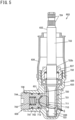
- FIG. 5 is a sectional view taken along A-A in FIG. 4 , illustrating part of the steering gear device 603.
- a lower side of the drawing corresponds to the lower side in the vertical direction when installed in the vehicle.
- the column type electric power steering system 601 includes a steering wheel 610, a steering shaft 602, a pinion shaft 632, a rack shaft 631, a housing 633, two rack bushings 630 and 634, two bearings 635 and 636, a rack guide mechanism 639, and a steering assistance device 4.
- a driver who drives an automobile including the column type electric power steering system 601 performs steering operations by turning the steering wheel 610.
- the steering shaft 602 includes a column shaft 621, a first universal joint 623, an intermediate shaft 622, and a second universal joint 624.
- the first universal joint 623 includes a first yoke that is omitted from illustration, a plurality of first rolling elements that is omitted from illustration, a first joint spider that is omitted from illustration, a plurality of second rolling elements that is omitted from illustration, and a second yoke that is omitted from illustration.
- the second universal joint 624 includes a third yoke that is omitted from illustration, a plurality of third rolling elements that is omitted from illustration, a second joint spider that is omitted from illustration, a plurality of fourth rolling elements that is omitted from illustration, and a fourth yoke that is omitted from illustration.
- the column shaft 621 fixes the steering wheel 610 at one end thereof in the extending direction.
- the column shaft 621 fixes the first yoke of the first universal joint 623 at the other end thereof in the extending direction.
- the column shaft 621 is rotatable about a central axis in the extending direction.
- the first yoke is pivotably fitted to a first pair of trunnions located on the same central axis of the first joint spider via the plurality of first rolling elements.
- the second yoke is pivotably fitted to a second pair of trunnions located on the same central axis of the first joint spider via the plurality of second rolling elements.
- the central axes of the first pair of trunnions and the central axes of the second pair of trunnions intersect at an angle of 90 degrees.
- the second yoke of the first universal joint 623 fixes one end of the intermediate shaft 622 in the extending direction thereof.
- the intermediate shaft 622 fixes the third yoke of the second universal joint 624 at the other end thereof in the extending direction.
- the third yoke is pivotably fitted to a third pair of trunnions located on the same central axis of the second joint spider via the plurality of third rolling elements.
- the fourth yoke is pivotably fitted to a fourth pair of trunnions located on the same central axis of the second joint spider via the plurality of fourth rolling elements.
- the central axes of the third pair of trunnions and the central axes of the fourth pair of trunnions intersect at an angle of 90 degrees.
- the fourth yoke of the second universal joint 624 fixes one end of the pinion shaft 632 in the extending direction thereof.
- the column shaft 621 turns about the central axis thereof in the extending direction thereof
- the intermediate shaft 622 also turns about a central axis thereof in the extending direction thereof
- the pinion shaft 632 also turns about a central axis thereof in the extending direction thereof.
- the pinion shaft 632, the rack shaft 631, the housing 633, the two rack bushings 630 and 634, the two bearings 635 and 636, and the rack guide mechanism 639 constitute the steering gear device 603 that serves as a rack and pinion type steering device.
- the housing 633 is represented by a hidden outline (long dashed double-short dashed lines), and inside thereof is illustrated.
- the pinion shaft 632 extends from the upper side to the lower side of the automobile in the vertical direction.
- the pinion shaft 632 includes, from one end side toward the other end in the extending direction thereof, a serrated portion 724, a shaft portion 722, a pinion toothed portion 720, and a boss portion 723. Serrations are formed in the serrated portion 724.
- the fourth yoke of the second universal joint 624 is fixed to the serrations of the serrated portion 724.
- the shaft portion 722 has a columnar shape.
- Pinion teeth 721 are formed over the entire face of the pinion toothed portion 720 in the circumferential direction.
- An extending direction of the pinion teeth 721 has an angle that is not 90 degrees with respect to the extending direction of the central axis of the pinion shaft 632.
- the boss portion 723 has a columnar shape.
- the housing 633 has a first opening 732 on the steering wheel 610 side, and a side opposite to the first opening 732 is sealed off.
- the pinion shaft 632 is accommodated within the housing 633.
- the pinion shaft 632 is supported by the two bearings 635 and 636 so as to be rotatable relative to the housing 633.
- the bearing 635 is a ball bearing.
- the bearing 635 includes an inner ring, an outer ring, and balls, with the inner ring being fixed to the shaft portion 722 and also the outer ring being fixed to the housing 633, and the balls roll between the inner ring and the outer ring.
- the bearing 636 is a roller bearing.
- the bearing 636 includes rollers and an outer ring, with the outer ring being fixed to the housing 633, and the rollers roll between an outer peripheral face of the boss portion 723 and the outer ring.
- a lid 637 through which the pinion shaft 632 passes is fixed to the first opening 732 of the housing in a state in which the pinion shaft 632 and the two bearings 635 and 636 are inserted into the housing 633.
- a seal is fixed to the lid 637, and the seal is slidable on an outer peripheral face 722b of the shaft portion 722 of the pinion shaft 632.
- a cover member 638 is further fixed to the housing 633. The cover member 638 covers part of the shaft portion 722 of the pinion shaft 632 from the outside in the radial direction.
- the rack shaft 631 includes, from one end toward the other end in an extending direction thereof, a first columnar portion 716, a rack toothed portion 710, and a second columnar portion 717.
- the rack toothed portion 710 has rack teeth 711 formed on part thereof in the circumferential direction, and the other part thereof in the circumferential direction is a cylindrical face 712 having a central axis corresponding to the extending direction of the rack shaft 631.
- An outer peripheral face of the first columnar portion 716 and an outer peripheral face of the second columnar portion 717 are each a cylindrical face having a central axis corresponding to the extending direction of the rack shaft 631.
- the extending direction of the rack teeth 711 has an angle that is not 90 degrees with respect to the extending direction of the rack shaft 631.
- the housing 633 extends in a direction different from that of the first opening 732 on the steering wheel 610 side, and has a second opening 733 at one end in the extending direction and a third opening 734 at the other end in the extending direction.
- the rack shaft 631 is accommodated within the housing 633 along the extending direction of the housing 633.
- One end of the rack shaft 631 in the extending direction thereof protrudes from the second opening 733 at one end of the housing 633 in the extending direction thereof.
- the other end of the rack shaft 631 in the extending direction thereof protrudes from the third opening 734 at the other end of the housing 633 in the extending direction thereof.
- the first rack bushing 630 is fixed to one end of the housing 633 in the extending direction.
- the first rack bushing 630 is fixed to the housing 633 to adjoin the second opening 733.
- the first rack bushing 630 is slidable on the outer peripheral face of the first columnar portion 716 of the rack shaft 631.
- the second rack bushing 634 is fixed to the other end of the housing 633 in the extending direction.
- the second rack bushing 634 is fixed to the housing 633 to adjoin the third opening 734.
- the second rack bushing 634 is slidable on the outer peripheral face of the second columnar portion 717 of the rack shaft 631.
- the pinion teeth 721 formed on the pinion toothed portion 720 of the pinion shaft 632 and the rack teeth 711 formed on the rack toothed portion 710 of the rack shaft 631 are in contact with each other so as to be rolling-slidable via the grease composition G.
- the pinion teeth 721 and the rack teeth 711 mesh with each other via the grease composition G.
- the housing 633 is fixed to the automobile that is omitted from illustration, with the extending direction of the housing 633 aligned with a vehicle-width direction.
- Ball joint sockets 11, 11 are fixed to one end and the other end of the rack shaft 631, respectively, and tie rods 12, 12 connected to the ball joint sockets 11, 11, respectively, are connected to bearing rings of rolling bearings that rotatably support a pair of right and left front wheels 14, 14 via knuckle arms 13, 13.
- the linear movement of the rack shaft 631 in the extending direction of the housing 633 steers the right and left front wheels 14, 14 that are steered wheels.
- the rack guide mechanism 639 is fixed to the housing 633.
- the housing 633 has a fourth opening 736 located on the cylindrical face 712 side that is the other part of the rack toothed portion 710 of the rack shaft 631 in the circumferential direction at a position where the pinion shaft 632 meshes with the rack shaft 631 in the extending direction.
- the rack guide mechanism 639 includes a support yoke 791, a sheet member 792, a coil spring 793, and a plug 794.
- the sheet member 792 is interposed between the cylindrical face 712 that is the other part of the rack toothed portion 710 of the rack shaft 631 in the circumferential direction and the cylindrical face of the support yoke 791.
- the sheet member 792 is fixed to the support yoke 791.
- the sheet member 792 and the cylindrical face 712 that is the other part of the rack toothed portion 710 of the rack shaft 631 in the circumferential direction are in contact with each other so as to be slidable via the grease composition G.
- the sheet member 792 includes a metal layer of, for example, bronze and a resin layer of, for example, PTFE, and the resin layer is in contact with the cylindrical face 712 via the grease composition G.
- the plug 794 is fixed to the fourth opening 736 of the housing 633.
- the plug 794 is in contact with one end of the coil spring 793.
- the support yoke 791 is in contact with the other end of the coil spring 793.
- the coil spring 793 is shorter than a free length thereof in a state in which the plug 794 is fixed to the fourth opening 736.
- the sheet member 792 is pressed against the rack shaft 631 with respect to the housing 633.
- the steering assistance device 4 includes a controller 40, a torque sensor 41 that detects steering torque applied by the driver to the steering wheel 610, an electric motor 42, and a speed reducing mechanism 43 that reduces the speed of rotational force of an output shaft 421 of the electric motor 42 and transmits the rotational force to the column shaft 621.
- the speed reducing mechanism 43 is an assembly in which a worm 431 that rotates together with the output shaft 421 of the electric motor 42 and a worm wheel 432 that rotates together with the column shaft 621 mesh with each other. A motor current is supplied to the electric motor 42 from the controller 40.
- the controller 40 controls the electric motor 42 based on the steering torque detected by the torque sensor 41, vehicle speed, etc., and applies the rotational force of the output shaft 421 of the electric motor 42 that is reduced in speed by the speed reducing mechanism 43 to the column shaft 621 as a steering assisting force.
- the grease composition G is sealed within the housing 633.
- the grease composition G is applied between rolling and sliding faces of the pinion teeth 721 and rolling and sliding faces of the rack teeth 711 that are in contact with each other when the pinion teeth 721 and the rack teeth 711 mesh with each other, thereby lubricating both the rolling and sliding faces.
- the grease composition G is applied between a sliding face of the sheet member 792 and a sliding face of the cylindrical face 712 that is the other part of the rack toothed portion 710 of the rack shaft 631 in the circumferential direction, the sliding faces being in contact with each other when the sheet member 792 and the rack shaft 631 are pressed against each other, thereby lubricating both the sliding faces.
- the grease composition of the present disclosure is sealed as the grease composition G within the steering gear device 603 configured in this way.
- the grease composition of the present disclosure can satisfactorily lubricate the meshing portion between the pinion teeth 721 and the first rack teeth 711, and the sliding contact portion between the sheet member 792 of the rack guide mechanism 639 and the rack shaft 631. Therefore, the amounts of wear in these portions can be reduced.
- the grease composition of the present disclosure can be used by being sealed within the dual-pinion type electric power steering system, the column type electric power steering system, etc.
- a grease composition according to an embodiment of the present disclosure includes a base oil, a thickener, and an extreme pressure additive.
- the base oil is a mixture containing poly- ⁇ -olefin (PAO) and trimellitate ester.
- poly- ⁇ -olefin examples include oligomerized or polymerized ⁇ -olefins such as 1-hexene, 1-octene, 1-nonene, 1-decene, 1-dodecene, and 1-tetradecene, and further hydrides thereof.
- the base oil kinematic viscosity of the poly- ⁇ -olefin at 40°C is preferably 20 to 60 mm 2 /s.
- the base oil kinematic viscosity (40°C) is more preferably 25 to 55 mm 2 /s.
- the base oil kinematic viscosity of the trimellitate triester at 40°C is preferably 37 to 57 mm 2 /s.
- the grease composition of the present disclosure contains lithium 12-hydroxystearate and lithium stearate as the thickener.
- the grease composition uses lithium stearate and lithium 12-hydroxystearate in combination to suppress the torque increase at low temperature.
- the proportion of lithium 12-hydroxystearate to the total amount of lithium 12-hydroxystearate and lithium stearate is 5.0 mass% or more and 95.0 mass% or less.
- the proportion of lithium 12-hydroxystearate to the total amount of lithium 12-hydroxystearate and lithium stearate is preferably 20.0 mass% or more and 75.0 mass% or less, and more preferably 25.0 mass% or more and 60.0 mass% or less.
- the grease composition of the present disclosure contains molybdenum dialkyl dithiocarbamate as the extreme pressure additive.
- the proportion of the molybdenum dialkyl dithiocarbamate (hereinafter also referred to as MoDTC) to the total amount of the trimellitate ester and the poly- ⁇ -olefin as the base oil, the lithium 12-hydroxystearate and the lithium stearate as the thickener, and the molybdenum dialkyl dithiocarbamate (hereinafter also referred to as MoDTC proportion) is 0.6 mass% or more and 16.0 mass% or less. This case is suitable for forming a tribo-reaction film on the friction face of the lubricated member. Therefore, wear of the friction face can be reduced.
- the MoDTC proportion is preferably 1.0 mass% or more and 10.0 mass% or less, and more preferably 1.3 mass% or more and 8.3 mass% or less.
- the MoDTC proportion that is 1.3 mass% or more and 8.3 mass% or less is particularly suitable for achieving both suppression of wear of the friction face of a lubricated member made of steel and suppression of wear of the friction face of a lubricated member made of resin such as fluororesin.
- Examples of the MoDTC include a compound represented by the following formula (1). (In the formula, R 1 to R 4 each independently represent a linear or branched alkyl group.)
- a commercially available product can also be used as the MoDTC.
- Examples of the commercially available product include ADEKA SAKURA-LUBE 200, ADEKA SAKURA-LUBE 165, ADEKA SAKURA-LUBE 525, and ADEKA SAKURA-LUBE 600 (all produced by ADEKA Corporation).
- the grease composition may contain additives other than the extreme pressure additive as long as the effects of the invention of the present disclosure are not impaired.
- the other additives include antioxidants, rust inhibitors, anti-wear agents, dyes, hue stabilizers, viscosity improvers, structural stabilizers, metal deactivators, and viscosity index improvers.
- the total content of the other additives in the grease composition is preferably 15 mass% or less with respect to the total mass of the base oil and the thickener.
- the grease composition of the present disclosure can suitably be used in the steering gear device of the automobile, etc.
- the grease composition can also be used as a grease composition to be sealed within a rolling bearing etc.
- the above grease composition can be produced by mixing the components. Specifically, the grease composition can be produced through, for example, the following procedure.
- the above grease composition can be produced through such steps (1) to (3).
- Molybdenum dialkyl dithiocarbamate (MoDTC): SAKURA-LUBE 600 (produced by ADEKA Corporation)
- a grease composition was completed in the same way as in Example 1 except that the amount of poly- ⁇ -olefin was 68.8 parts by mass, the amount of trimellitate ester was 17.2 parts by mass, and the amount of MoDTC was 2.0 parts by mass.
- a grease composition was completed in the same way as in Example 1 except that the amount of poly- ⁇ -olefin was 66.7 parts by mass, the amount of trimellitate ester was 16.7 parts by mass, the amounts of lithium stearate and lithium 12-hydroxystearate were each 5.8 parts by mass, and the amount of MoDTC was 5.0 parts by mass.
- a grease composition was completed in the same way as in Example 1 except that the amount of poly- ⁇ -olefin was 63.2 parts by mass, the amount of trimellitate ester was 15.8 parts by mass, the amounts of lithium stearate and lithium 12-hydroxystearate were each 5.5 parts by mass, and the amount of MoDTC was 10.0 parts by mass.
- a grease composition was completed in the same way as in Example 1 except that the amount of poly- ⁇ -olefin was 59.7 parts by mass, the amount of trimellitate ester was 14.9 parts by mass, the amounts of lithium stearate and lithium 12-hydroxystearate were each 5.2 parts by mass, and the amount of MoDTC was 15.0 parts by mass.
- a grease composition was completed in the same way as in Example 1 except that the amount of poly- ⁇ -olefin was 69.8 parts by mass, the amount of trimellitate ester was 17.5 parts by mass, the amounts of lithium stearate and lithium 12-hydroxystearate were each 6.1 parts by mass, and the amount of MoDTC was 0.5 parts by mass.
- a grease composition was completed in the same way as in Example 6 except that diester was used instead of trimellitate ester.
- a grease composition was completed in the same way as in Example 6 except that phthalate ester was used instead of trimellitate ester.
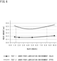
- the grease compositions produced in the Examples and Comparative Examples were subjected to a friction and wear test to evaluate wear resistance under a poor lubrication environment. Two types of friction and wear test were carried out by using test pieces made of different materials. The results are shown in Table 3 and FIG. 6 .
- test was carried out in conformity with the ASTM D5707 standard.
- An SRV2 vibration friction and wear tester manufactured by OPTIMOL was used as the test device.
- a cylindrical roller for bearings made of SUJ2 ( ⁇ 15 mm ⁇ 22 mm, Ra 0.1 ⁇ m) was used as an upper test piece, and a flat plate made of SUJ2 ( ⁇ 24 mm ⁇ 7.8 mm, Ra 0.2 ⁇ m) was used as a lower test piece.
- the upper test piece was caused to reciprocate along the axial direction of the cylindrical roller for 10 minutes while being pressed against the lower test piece with a load of 250 N, and the width of a wear mark formed on the flat plate was measured.
Landscapes
- Chemical & Material Sciences (AREA)
- Engineering & Computer Science (AREA)
- General Engineering & Computer Science (AREA)
- Mechanical Engineering (AREA)
- Chemical Kinetics & Catalysis (AREA)
- General Chemical & Material Sciences (AREA)
- Oil, Petroleum & Natural Gas (AREA)
- Organic Chemistry (AREA)
- Combustion & Propulsion (AREA)
- Transportation (AREA)
- Power Steering Mechanism (AREA)
- Transmission Devices (AREA)
Abstract
Description
- The present disclosure relates to a grease composition and a steering gear device.
- This application claims priority based on the international application No.
PCT/JP2022/003775 filed on February 1, 2022 - A rack and pinion provided in a steering gear device for use in an electric power steering system include a rack shaft having rack teeth and a pinion shaft having pinion teeth. In this steering gear device, wear of the rack teeth and the pinion teeth is suppressed by applying grease to a meshing portion between the rack teeth and the pinion teeth. This reduces the amount of change in the clearance between the rack teeth and the pinion teeth, thereby maintaining the steering performance of the electric power steering system. Greases for use in steering gear devices are proposed in, for example,
Patent Documents 1 to 3. -
- Patent Document 1:
Japanese Unexamined Patent Application Publication No. 2001-064665 JP 2001-064665 A - Patent Document 2:
Japanese Unexamined Patent Application Publication No. 2009-203374 JP 2009-203374 A - Patent Document 3:
Japanese Unexamined Patent Application Publication No. 2004-269722 JP 2004-269722 A - A grease composition according to one aspect of the present disclosure includes a base oil, a thickener, and an extreme pressure additive. The base oil contains trimellitate ester and poly-α-olefin. A proportion of the trimellitate ester to a total amount of the trimellitate ester and the poly-α-olefin is 10.0 mass% or more and 60.0 mass% or less. The thickener contains lithium 12-hydroxystearate and lithium stearate. A proportion of the lithium 12-hydroxystearate to a total amount of the lithium 12-hydroxystearate and the lithium stearate is 5.0 mass% or more and 95.0 mass% or less. The extreme pressure additive contains molybdenum dialkyl dithiocarbamate. A proportion of the molybdenum dialkyl dithiocarbamate to a total amount of the trimellitate ester, the poly-α-olefin, the lithium 12-hydroxystearate, the lithium stearate, and the molybdenum dialkyl dithiocarbamate is 0.6 mass% or more and 16.0 mass% or less.
- A steering gear device according to one aspect of the present disclosure includes: a housing; a rack shaft including rack teeth and configured to reciprocate along an axial direction; a pinion shaft including pinion teeth that mesh with the rack teeth; a rack guide mechanism that urges the rack teeth against the pinion teeth; and a grease composition applied between the rack teeth and the pinion teeth that mesh with each other, and between a peripheral face of the rack shaft and a portion of the rack guide mechanism that is pressed against the rack shaft. The grease composition is the grease composition of the present disclosure.
-
- [
FIG. 1] FIG. 1 is a configuration diagram schematically illustrating an example of a dual-pinion type electric power steering system in which a grease composition of the present disclosure is sealed. - [
FIG. 2] FIG. 2 is a sectional view taken along A-A inFIG. 1 . - [
FIG. 3] FIG. 3 is a sectional view taken along B-B inFIG. 1 . - [
FIG. 4] FIG. 4 is a configuration diagram schematically illustrating an example of a column type electric power steering system in which the grease composition of the present disclosure is sealed. - [
FIG. 5] FIG. 5 is a sectional view taken along A-A inFIG. 4 . - [
FIG. 6] FIG. 6 is a graph illustrating evaluation results of Examples and Comparative Examples. - In a steering gear device including a rack and pinion, wear of rack teeth and pinion teeth of the rack and pinion is suppressed by applying a grease composition to a meshing portion between the rack teeth and the pinion teeth. The above steering gear device includes a rack guide mechanism for urging the rack teeth against the pinion teeth, and a grease composition is also applied between a rack shaft and a portion of the rack guide mechanism that is pressed against the rack shaft to suppress wear of them.
- Therefore, in the above steering gear device, there is a demand for a grease composition that can satisfactorily lubricate not only the meshing portion between the rack teeth and the pinion teeth of the rack and pinion but also the sliding contact portion between the rack shaft and the rack guide mechanism.
- However, it has been difficult for the grease compositions proposed in
Patent Documents 1 to 3 to fully meet such a demand. - The meshing portion between the rack teeth and the pinion teeth and the sliding contact portion between the rack shaft and the rack guide mechanism are lubricated portions that are prone to poor lubrication. It has not been easy to lubricate such portions satisfactorily.
- The portion of the rack guide mechanism that is pressed against the rack shaft is made of a resin such as PTFE, and a grease composition designed for lubricating the meshing portion between the steel rack teeth and the steel pinion teeth has sometimes been unable to satisfactorily lubricate the sliding contact portion between the rack shaft and the rack guide mechanism.
- The grease composition of the present disclosure is easily adsorbed to the friction face of a lubricated member and easily remains on the friction face by forming a tribo-reaction film. Therefore, the grease composition exhibits excellent lubricating performance even when used in portions prone to poor lubrication, and can suppress wear on the friction face of the lubricated member. Therefore, the grease composition is suitable for use in the steering gear device including the rack and pinion.
- Since the steering gear device of the present disclosure uses the grease composition of the present disclosure, it is possible to suppress wear over a long period of time on the rack teeth and the pinion teeth, the peripheral face of the rack shaft that comes into sliding contact with the rack guide mechanism, and the portion of the rack guide mechanism that is pressed against the rack shaft. Therefore, the above steering gear device can maintain the steering performance for a long period of time.
- Hereinafter, an overview of embodiments of the invention of the present disclosure will be described on a list.
- (1) A grease composition of the present disclosure includes a base oil, a thickener, and an extreme pressure additive. The base oil contains trimellitate ester and poly-α-olefin. A proportion of the trimellitate ester to a total amount of the trimellitate ester and the poly-α-olefin is 10.0 mass% or more and 60.0 mass% or less. The thickener contains lithium 12-hydroxystearate and lithium stearate. A proportion of the lithium 12-hydroxystearate to a total amount of the lithium 12-hydroxystearate and the lithium stearate is 5.0 mass% or more and 95.0 mass% or less. The extreme pressure additive contains molybdenum dialkyl dithiocarbamate. A proportion of the molybdenum dialkyl dithiocarbamate to a total amount of the trimellitate ester, the poly-α-olefin, the lithium 12-hydroxystearate, the lithium stearate, and the molybdenum dialkyl dithiocarbamate is 0.6 mass% or more and 16.0 mass% or less.
- The grease composition is easily adsorbed to the friction face of a lubricated member and is unlikely to be desorbed from the friction face because the base oil contains predetermined amounts of trimellitate ester and poly-α-olefin and the thickener contains predetermined amounts of lithium stearate and lithium 12-hydroxystearate.
In addition, a tribo-reaction film is easily formed on the friction face because the grease composition contains a predetermined amount of molybdenum dialkyl dithiocarbamate as the extreme pressure additive.
Therefore, the grease composition is suitable for lubricating the friction face of the lubricated member prone to be in a poor lubrication environment, and for suppressing wear of the friction face. - (2) In the grease composition of (1) above, the proportion of the molybdenum dialkyl dithiocarbamate to the total amount of the trimellitate ester, the poly-α-olefin, the lithium 12-hydroxystearate, the lithium stearate, and the molybdenum dialkyl dithiocarbamate is preferably 1.3 mass% or more and 8.3 mass% or less.
In this case, the grease composition is more suitable for achieving both suppression of wear of the friction face of a lubricated member made of steel and suppression of wear of the friction face of a lubricated member made of resin. - (3) A steering gear device of the present disclosure includes: a housing; a rack shaft including rack teeth and configured to reciprocate along an axial direction; a pinion shaft including pinion teeth that mesh with the rack teeth; a rack guide mechanism that urges the rack teeth against the pinion teeth; and a grease composition applied between the rack teeth and the pinion teeth that mesh with each other, and between a peripheral face of the rack shaft and a portion of the rack guide mechanism that is pressed against the rack shaft. The grease composition is the grease composition of the present disclosure.
- In the steering gear device, the grease composition applied between the rack teeth and the pinion teeth that mesh with each other and between the peripheral face of the rack shaft and the portion of the rack guide mechanism that is pressed against the rack shaft is the grease composition of the present disclosure. In this case, wear is suppressed on the rack teeth, the pinion teeth, the peripheral face of the rack shaft that comes into sliding contact with the rack guide mechanism, and the portion of the rack guide mechanism that is pressed against the rack shaft. Therefore, the amount of change in the clearance in the lubricated portion due to wear is small, and a decrease in steering performance etc. is less likely to occur.
- Embodiments of the present disclosure will be described below.
- In the present disclosure, the embodiments of the invention should be understood as being exemplary in all respects and not restrictive. The scope of rights of the present invention is set forth in the claims, and is intended to include all modifications within the meaning and scope equivalent to the claims.
- First, a steering gear device using the grease composition of the present disclosure will be described, followed by description of embodiments relating to the grease composition of the present disclosure.
- The grease composition of the present disclosure is used in, for example, dual-pinion type electric power steering systems and column type electric power steering systems.
-
FIG. 1 is a configuration diagram schematically illustrating an example of a dual-pinion type electricpower steering system 1 including asteering gear device 3. -
FIG. 2 is a sectional view taken along A-A inFIG. 1 , illustrating part of thesteering gear device 3. InFIG. 2 , a lower side of the drawing corresponds to a lower side in a vertical direction when installed in a vehicle. -
FIG. 3 is a sectional view taken along B-B inFIG. 1 , illustrating part of thesteering gear device 3. InFIG. 3 , a lower side of the drawing corresponds to the lower side in the vertical direction when installed in the vehicle. - The dual-pinion type electric
power steering system 1 includes asteering wheel 10, asteering shaft 2, afirst pinion shaft 32, arack shaft 31, ahousing 33, tworack bushings bearings rack guide mechanism 39, and a steering assistance device 5. The steering assistance device 5 includes acontroller 50, atorque sensor 51, anelectric motor 52, aspeed reducing mechanism 53, asecond pinion shaft 54, twobearings worm housing 57, and a secondrack guide mechanism 59. Thespeed reducing mechanism 53 includes aworm 531 and aworm wheel 532. - A driver who drives an automobile including the dual-pinion type electric
power steering system 1 performs steering operations by turning thesteering wheel 10. The steeringshaft 2 includes acolumn shaft 21, a firstuniversal joint 23, an intermediate shaft 22, and a seconduniversal joint 24. The firstuniversal joint 23 includes a first yoke that is omitted from illustration, a plurality of first rolling elements that is omitted from illustration, a first joint spider that is omitted from illustration, a plurality of second rolling elements that is omitted from illustration, and a second yoke that is omitted from illustration. The seconduniversal joint 24 includes a third yoke that is omitted from illustration, a plurality of third rolling elements that is omitted from illustration, a second joint spider that is omitted from illustration, a plurality of fourth rolling elements that is omitted from illustration, and a fourth yoke that is omitted from illustration. - The
column shaft 21 fixes thesteering wheel 10 at one end thereof in an extending direction. Thecolumn shaft 21 fixes the first yoke of the first universal joint 23 at the other end thereof in the extending direction. Thecolumn shaft 21 is rotatable about a central axis in the extending direction. The first yoke is pivotably fitted to a first pair of trunnions located on the same central axis of the first joint spider via the plurality of first rolling elements. The second yoke is pivotably fitted to a second pair of trunnions located on the same central axis of the first joint spider via the plurality of second rolling elements. The central axes of the first pair of trunnions and the central axes of the second pair of trunnions intersect at an angle of 90 degrees. - The second yoke of the first universal joint 23 fixes one end of the intermediate shaft 22 in the extending direction thereof. The intermediate shaft 22 fixes the third yoke of the second universal joint 24 at the other end thereof in the extending direction. The third yoke is pivotably fitted to a third pair of trunnions located on the same central axis of the second joint spider via the plurality of third rolling elements. The fourth yoke is pivotably fitted to a fourth pair of trunnions located on the same central axis of the second joint spider via the plurality of fourth rolling elements. The central axes of the third pair of trunnions and the central axes of the fourth pair of trunnions intersect at an angle of 90 degrees. The fourth yoke of the second universal joint 24 fixes one end of the
first pinion shaft 32 in the extending direction thereof. Thus, when the driver turns thesteering wheel 10, thecolumn shaft 21 turns about the central axis thereof in the extending direction thereof, the intermediate shaft 22 also turns about a central axis thereof in the extending direction thereof, and thefirst pinion shaft 32 also turns about a central axis thereof in the extending direction thereof. - In the dual-pinion type electric
power steering system 1, thefirst pinion shaft 32, therack shaft 31, thehousing 33, the tworack bushings first bearing 35, thesecond bearing 36, the firstrack guide mechanism 39, theelectric motor 52, thespeed reducing mechanism 53, thesecond pinion shaft 54, thethird bearing 55, thefourth bearing 56, theworm housing 57, and the secondrack guide mechanism 59 constitute thesteering gear device 3 that serves as a rack and pinion type steering device. InFIG. 1 , thehousing 33 is represented by a hidden outline (long dashed double-short dashed lines), and inside thereof is illustrated. - The
first pinion shaft 32 extends from an upper side to a lower side of the automobile in the vertical direction. Thefirst pinion shaft 32 includes, from one end side toward the other end in the extending direction thereof, aserrated portion 324, afirst shaft portion 322, a first piniontoothed portion 320, and afirst boss portion 323. Serrations are formed in theserrated portion 324. The fourth yoke of the seconduniversal joint 24 is fixed to the serrations of theserrated portion 324. Thefirst shaft portion 322 has a columnar shape.First pinion teeth 321 are formed over the entire face of the first piniontoothed portion 320 in the circumferential direction. An extending direction of thefirst pinion teeth 321 has an angle that is not 90 degrees with respect to the extending direction of the central axis of thefirst pinion shaft 32. Thefirst boss portion 323 has a columnar shape. - The
housing 33 has afirst opening 332 on thesteering wheel 10 side, and a side opposite to thefirst opening 332 is sealed off. Thefirst pinion shaft 32 is accommodated within thehousing 33. Thefirst pinion shaft 32 is supported by the twobearings housing 33. Thefirst bearing 35 is a ball bearing. Thefirst bearing 35 includes an inner ring, an outer ring, and balls, with the inner ring being fixed to thefirst shaft portion 322 and also the outer ring being fixed to thehousing 33, and the balls roll between the inner ring and the outer ring. Thesecond bearing 36 is a roller bearing. Thesecond bearing 36 includes rollers and an outer ring, with the outer ring being fixed to thehousing 33, and the rollers roll between an outer peripheral face of thefirst boss portion 323 and the outer ring. - A
lid 37 through which thefirst pinion shaft 32 passes is fixed to thefirst opening 332 of the housing in a state in which thefirst pinion shaft 32, thefirst bearing 35, and thesecond bearing 36 are inserted into thehousing 33. A seal is fixed to thelid 37, and the seal is slidable on an outerperipheral face 322b of thefirst shaft portion 322 of thefirst pinion shaft 32. Acover member 38 is further fixed to thehousing 33. Thecover member 38 covers part of thefirst shaft portion 322 of thefirst pinion shaft 32 from the outside in a radial direction. - The
rack shaft 31 includes, from one end toward the other end in an extending direction thereof, a firstcolumnar portion 316, a first racktoothed portion 310, a secondcolumnar portion 317, a second racktoothed portion 314, and a thirdcolumnar portion 318. The first racktoothed portion 310 hasfirst rack teeth 311 formed on part thereof in the circumferential direction, and the other part thereof in the circumferential direction is acylindrical face 312 having a central axis corresponding to the extending direction of therack shaft 31. The second racktoothed portion 314 hassecond rack teeth 315 formed on part thereof in the circumferential direction, and the other part thereof in the circumferential direction is acylindrical face 313 having a central axis corresponding to the extending direction of therack shaft 31. An outer peripheral face of the firstcolumnar portion 316, an outer peripheral face of the secondcolumnar portion 317, and an outer peripheral face of the thirdcolumnar portion 318 are each a cylindrical face having a central axis corresponding to the extending direction of therack shaft 31. The extending direction of thefirst rack teeth 311 has an angle that is not 90 degrees with respect to the extending direction of the rack shaft. The extending direction of thesecond rack teeth 315 has an angle that is not 90 degrees with respect to the extending direction of therack shaft 31. Assuming that the angle of thefirst rack teeth 311 with respect to the extending direction of therack shaft 31 is X, the angle of thesecond rack teeth 315 with respect to the extending direction of therack shaft 31 is π - X. - The
housing 33 extends in a direction different from that of thefirst opening 332 on thesteering wheel 10 side, and has asecond opening 333 at one end in the extending direction and athird opening 334 at the other end in the extending direction. Therack shaft 31 is accommodated within thehousing 33 along the extending direction of thehousing 33. The firstcolumnar portion 316 at one end of therack shaft 31 in the extending direction thereof protrudes from thesecond opening 333 at one end of thehousing 33 in the extending direction thereof. The thirdcolumnar portion 318 at the other end of therack shaft 31 in the extending direction thereof protrudes from thethird opening 334 at the other end of thehousing 33 in the extending direction thereof. Thehousing 33 has afourth opening 335. Thefourth opening 335 is located closer to the other end of the housing in the extending direction than thefirst opening 332 is. Thehousing 33 further has afifth opening 336 and asixth opening 337. Thefifth opening 336 is located at approximately the same position as that of thefirst opening 332 in the extending direction of thehousing 33 to extend in a radial direction about a central axis corresponding to the extending direction of thehousing 33, that is, in a direction perpendicular to thefirst opening 332. Thesixth opening 337 is located at approximately the same position as that of thefourth opening 335 in the extending direction of thehousing 33 to extend in a radial direction about a central axis corresponding to the extending direction of thehousing 33, that is, in a direction perpendicular to thefourth opening 335. - The
first rack bushing 30 is fixed to one end of thehousing 33 in the extending direction. Thefirst rack bushing 30 is fixed to thehousing 33 to adjoin thesecond opening 333. Thefirst rack bushing 30 is slidable on the outer peripheral face of the firstcolumnar portion 316 of therack shaft 31. Thesecond rack bushing 34 is fixed to the other end of thehousing 33 in the extending direction. Thesecond rack bushing 34 is fixed to thehousing 33 to adjoin thethird opening 334. Thesecond rack bushing 34 is slidable on the outer peripheral face of the thirdcolumnar portion 318 of therack shaft 31. - The
first pinion teeth 321 formed on the first piniontoothed portion 320 of thefirst pinion shaft 32 and thefirst rack teeth 311 formed on the first racktoothed portion 310 of therack shaft 31 are in contact with each other so as to be rolling-slidable via a grease composition G. Thefirst pinion teeth 321 and thefirst rack teeth 311 mesh with each other via the grease composition G. When thefirst pinion shaft 32 turns relative to thehousing 33 about the central axis in the extending direction thereof, therack shaft 31 moves in a linear direction relative to thehousing 33 in the extending direction of thehousing 33. - The first
rack guide mechanism 39 is fixed to thehousing 33. The firstrack guide mechanism 39 is fixed to thefifth opening 336. Thefifth opening 336 is located on thecylindrical face 312 side that is the other part of the first racktoothed portion 310 of therack shaft 31 in the circumferential direction at a position where thefirst pinion shaft 32 meshes with therack shaft 31 in the extending direction of thehousing 33. - The first
rack guide mechanism 39 includes afirst support yoke 391, afirst sheet member 392, afirst coil spring 393, and afirst plug 394. Thefirst sheet member 392 is interposed between thecylindrical face 312 that is the other part of the first racktoothed portion 310 of therack shaft 31 in the circumferential direction and the cylindrical face of thefirst support yoke 391. Thefirst sheet member 392 is fixed to thefirst support yoke 391. Thefirst sheet member 392 and thecylindrical face 312 that is the other part of the first racktoothed portion 310 of therack shaft 31 in the circumferential direction are in contact with each other so as to be slidable via the grease composition G. Thefirst sheet member 392 includes a metal layer of, for example, bronze and a resin layer of, for example, PTFE, and the resin layer is in contact with thecylindrical face 312 via the grease composition G. Thefirst plug 394 is fixed to thefifth opening 336 of thehousing 33. Thefirst plug 394 is in contact with one end of thefirst coil spring 393. Thefirst support yoke 391 is in contact with the other end of thefirst coil spring 393. Thefirst coil spring 393 is shorter than a free length thereof in a state in which thefirst plug 394 is fixed to thefifth opening 336. Thus, thefirst sheet member 392 is pressed against therack shaft 31 with respect to thehousing 33. - The
second pinion shaft 54 extends from the upper side to the lower side of the automobile in the vertical direction. Thesecond pinion shaft 54 includes, from one end side toward the other end along the extending direction thereof, afitting portion 544, asecond shaft portion 542, a second piniontoothed portion 540, and asecond boss portion 543. Thefitting portion 544 has a columnar shape. Thesecond shaft portion 542 has a columnar shape.Second pinion teeth 541 are formed over the entire face of the second piniontoothed portion 540 in the circumferential direction. An extending direction of thesecond pinion teeth 541 has an angle that is not 90 degrees with respect to the extending direction of the central axis of thesecond pinion shaft 54. Thesecond boss portion 543 has a columnar shape. - The
worm wheel 532 is fitted to thefitting portion 544. Theworm 531 is fixed to anoutput shaft 521 of theelectric motor 52. Theelectric motor 52 is fixed to theworm housing 57. Theworm housing 57 has aseventh opening 571. Theoutput shaft 521 of theelectric motor 52 is disposed in internal space of theworm housing 57 via theseventh opening 571. Theelectric motor 52 is fixed to theworm housing 57 so as to close off theseventh opening 571 of theworm housing 57. - The
worm 531 is disposed in the internal space of theworm housing 57. Theworm wheel 532 is disposed in the internal space of theworm housing 57. Theworm housing 57 has aneighth opening 572 vertically upward, and an assembly of thesecond pinion shaft 54 and theworm wheel 532 is inserted into the internal space of theworm housing 57 from theeighth opening 572. The eighth opening is closed with alid 58. Theworm housing 57 has aninth opening 573 on the opposite side from theeighth opening 572. Part of thesecond shaft portion 542 of thesecond pinion shaft 54, the second piniontoothed portion 540, and thesecond boss portion 543 protrude from theninth opening 573 of theworm housing 57. - The
worm housing 57 is fixed to thehousing 33. Theninth opening 573 of theworm housing 57 and thefourth opening 335 of thehousing 33 communicate with each other to seal off the internal space from the external space. - The
third bearing 55 is a ball bearing. Thebearing 55 includes an inner ring, an outer ring, and balls, with the inner ring being fixed to thesecond shaft portion 542 and also the outer ring being fixed to theworm housing 57, and the balls roll between the inner ring and the outer ring. Thebearing 56 is a roller bearing. Thebearing 56 includes rollers and an outer ring, with the outer ring being fixed to thehousing 33, and the rollers roll between an outer peripheral face of thesecond boss portion 543 and the outer ring. - The
second pinion teeth 541 formed on the second piniontoothed portion 540 of thesecond pinion shaft 54 and thesecond rack teeth 315 formed on the second racktoothed portion 314 of therack shaft 31 are in contact with each other so as to be rolling-slidable via the grease composition G. Thesecond pinion teeth 541 and thesecond rack teeth 315 mesh with each other via the grease composition G. When thesecond pinion shaft 54 turns relative to thehousing 33 about the central axis in the extending direction thereof, therack shaft 31 moves in the linear direction relative to thehousing 33 in the extending direction of thehousing 33. - The second
rack guide mechanism 59 is fixed to thehousing 33. The secondrack guide mechanism 59 is fixed to thesixth opening 337. Thesixth opening 337 is located on thecylindrical face 313 side that is the other part of the second racktoothed portion 314 of therack shaft 31 in the circumferential direction at a position where thesecond pinion shaft 54 meshes with therack shaft 31 in the extending direction of thehousing 33. - The second
rack guide mechanism 59 includes asecond support yoke 591, asecond sheet member 592, a second coil spring 593, and asecond plug 594. Thesecond sheet member 592 is interposed between thecylindrical face 313 that is the other part of the second racktoothed portion 314 of therack shaft 31 in the circumferential direction and the cylindrical face of thesecond support yoke 591. Thesecond sheet member 592 is fixed to thesecond support yoke 591. Thesecond sheet member 592 and thecylindrical face 313 that is the other part of the second racktoothed portion 314 of therack shaft 31 in the circumferential direction are in contact with each other so as to be slidable via the grease composition G. Thesecond sheet member 592 includes a metal layer of, for example, bronze and a resin layer of, for example, PTFE, and the resin layer is in contact with thecylindrical face 313 via the grease composition G. Thesecond plug 594 is fixed to thesixth opening 337 of thehousing 33. Thesecond plug 594 is in contact with one end of the second coil spring 593. Thesecond support yoke 591 is in contact with the other end of the second coil spring 593. The second coil spring 593 is shorter than a free length thereof in a state in which thesecond plug 594 is fixed to thesixth opening 337. Thus, thesecond sheet member 592 is pressed against therack shaft 31 with respect to thehousing 33. - The
torque sensor 51 detects steering torque applied by the driver to thesteering wheel 10 through thecolumn shaft 21. Thespeed reducing mechanism 53 is an assembly in which theworm 531 that rotates together with theoutput shaft 521 of theelectric motor 52 and theworm wheel 532 that rotates together with thesecond pinion shaft 54 mesh with each other. A motor current is supplied to theelectric motor 52 from thecontroller 50. Thecontroller 50 controls theelectric motor 52 based on the steering torque detected by thetorque sensor 51, vehicle speed, etc., and transmits, to thesecond pinion shaft 54, rotational force of theoutput shaft 521 of theelectric motor 52 that is reduced in speed by thespeed reducing mechanism 53. The rotational force of thesecond pinion shaft 54 is applied from thesecond pinion teeth 541 to thesecond rack teeth 315 as a steering assisting force. - The
housing 33 is fixed to the automobile that is omitted from illustration, with the extending direction of thehousing 33 aligned with a vehicle-width direction. Balljoint sockets rack shaft 31, respectively, andtie rods joint sockets front wheels knuckle arms rack shaft 31 in the extending direction of thehousing 33 steers the right and leftfront wheels - The grease composition G is sealed within the
housing 33. The grease composition G is applied between rolling and sliding faces of thefirst pinion teeth 321 and rolling and sliding faces of thefirst rack teeth 311 that are in contact with each other when thefirst pinion teeth 321 and thefirst rack teeth 311 mesh with each other, thereby lubricating both the rolling and sliding faces. The grease composition G is applied between a sliding face of thefirst sheet member 392 and a sliding face of thecylindrical face 312 that is the other part of the first racktoothed portion 310 of therack shaft 31 in the circumferential direction, the sliding faces being in contact with each other when thefirst sheet member 392 and therack shaft 31 are pressed against each other, thereby lubricating both the sliding faces. The grease composition G is applied between rolling and sliding faces of thesecond pinion teeth 541 and rolling and sliding faces of thesecond rack teeth 315 that are in contact with each other when thesecond pinion teeth 541 and thesecond rack teeth 315 mesh with each other, thereby lubricating both the rolling and sliding faces. The grease composition G is applied between a sliding face of thesecond sheet member 592 and a sliding face of thecylindrical face 313 that is the other part of the second racktoothed portion 314 of therack shaft 31 in the circumferential direction, the sliding faces being in contact with each other when thesecond sheet member 592 and therack shaft 31 are pressed against each other, thereby lubricating both the sliding faces. - The grease composition of the present disclosure is sealed as the grease composition G within the
steering gear device 3 configured in this way. The grease composition of the present disclosure can satisfactorily lubricate the meshing portion between thefirst pinion teeth 321 and thefirst rack teeth 311, the meshing portion between thesecond pinion teeth 541 and thesecond rack teeth 315, the sliding contact portion between thefirst sheet member 392 of the firstrack guide mechanism 39 and therack shaft 31, and the sliding contact portion between thesecond sheet member 592 of the secondrack guide mechanism 59 and therack shaft 31. Therefore, the amounts of wear in these portions can be reduced. -
FIG. 4 is a configuration diagram schematically illustrating an example of a column type electricpower steering system 601 including asteering gear device 603. -
FIG. 5 is a sectional view taken along A-A inFIG. 4 , illustrating part of thesteering gear device 603. InFIG. 5 , a lower side of the drawing corresponds to the lower side in the vertical direction when installed in the vehicle. - The column type electric
power steering system 601 includes asteering wheel 610, asteering shaft 602, apinion shaft 632, arack shaft 631, ahousing 633, tworack bushings bearings rack guide mechanism 639, and a steering assistance device 4. A driver who drives an automobile including the column type electricpower steering system 601 performs steering operations by turning thesteering wheel 610. The steeringshaft 602 includes acolumn shaft 621, a firstuniversal joint 623, anintermediate shaft 622, and a seconduniversal joint 624. The firstuniversal joint 623 includes a first yoke that is omitted from illustration, a plurality of first rolling elements that is omitted from illustration, a first joint spider that is omitted from illustration, a plurality of second rolling elements that is omitted from illustration, and a second yoke that is omitted from illustration. The seconduniversal joint 624 includes a third yoke that is omitted from illustration, a plurality of third rolling elements that is omitted from illustration, a second joint spider that is omitted from illustration, a plurality of fourth rolling elements that is omitted from illustration, and a fourth yoke that is omitted from illustration. - The
column shaft 621 fixes thesteering wheel 610 at one end thereof in the extending direction. Thecolumn shaft 621 fixes the first yoke of the firstuniversal joint 623 at the other end thereof in the extending direction. Thecolumn shaft 621 is rotatable about a central axis in the extending direction. The first yoke is pivotably fitted to a first pair of trunnions located on the same central axis of the first joint spider via the plurality of first rolling elements. The second yoke is pivotably fitted to a second pair of trunnions located on the same central axis of the first joint spider via the plurality of second rolling elements. The central axes of the first pair of trunnions and the central axes of the second pair of trunnions intersect at an angle of 90 degrees. - The second yoke of the first
universal joint 623 fixes one end of theintermediate shaft 622 in the extending direction thereof. Theintermediate shaft 622 fixes the third yoke of the seconduniversal joint 624 at the other end thereof in the extending direction. The third yoke is pivotably fitted to a third pair of trunnions located on the same central axis of the second joint spider via the plurality of third rolling elements. The fourth yoke is pivotably fitted to a fourth pair of trunnions located on the same central axis of the second joint spider via the plurality of fourth rolling elements. The central axes of the third pair of trunnions and the central axes of the fourth pair of trunnions intersect at an angle of 90 degrees. The fourth yoke of the seconduniversal joint 624 fixes one end of thepinion shaft 632 in the extending direction thereof. Thus, when the driver turns thesteering wheel 610, thecolumn shaft 621 turns about the central axis thereof in the extending direction thereof, theintermediate shaft 622 also turns about a central axis thereof in the extending direction thereof, and thepinion shaft 632 also turns about a central axis thereof in the extending direction thereof. - In the column type electric
power steering system 601, thepinion shaft 632, therack shaft 631, thehousing 633, the tworack bushings bearings rack guide mechanism 639 constitute thesteering gear device 603 that serves as a rack and pinion type steering device. InFIG. 4 , thehousing 633 is represented by a hidden outline (long dashed double-short dashed lines), and inside thereof is illustrated. - The
pinion shaft 632 extends from the upper side to the lower side of the automobile in the vertical direction. Thepinion shaft 632 includes, from one end side toward the other end in the extending direction thereof, aserrated portion 724, ashaft portion 722, a piniontoothed portion 720, and aboss portion 723. Serrations are formed in theserrated portion 724. The fourth yoke of the seconduniversal joint 624 is fixed to the serrations of theserrated portion 724. Theshaft portion 722 has a columnar shape.Pinion teeth 721 are formed over the entire face of the piniontoothed portion 720 in the circumferential direction. An extending direction of thepinion teeth 721 has an angle that is not 90 degrees with respect to the extending direction of the central axis of thepinion shaft 632. Theboss portion 723 has a columnar shape. - The
housing 633 has afirst opening 732 on thesteering wheel 610 side, and a side opposite to thefirst opening 732 is sealed off. Thepinion shaft 632 is accommodated within thehousing 633. Thepinion shaft 632 is supported by the twobearings housing 633. Thebearing 635 is a ball bearing. Thebearing 635 includes an inner ring, an outer ring, and balls, with the inner ring being fixed to theshaft portion 722 and also the outer ring being fixed to thehousing 633, and the balls roll between the inner ring and the outer ring. Thebearing 636 is a roller bearing. Thebearing 636 includes rollers and an outer ring, with the outer ring being fixed to thehousing 633, and the rollers roll between an outer peripheral face of theboss portion 723 and the outer ring. - A
lid 637 through which thepinion shaft 632 passes is fixed to thefirst opening 732 of the housing in a state in which thepinion shaft 632 and the twobearings housing 633. A seal is fixed to thelid 637, and the seal is slidable on an outerperipheral face 722b of theshaft portion 722 of thepinion shaft 632. Acover member 638 is further fixed to thehousing 633. Thecover member 638 covers part of theshaft portion 722 of thepinion shaft 632 from the outside in the radial direction. - The
rack shaft 631 includes, from one end toward the other end in an extending direction thereof, a firstcolumnar portion 716, a racktoothed portion 710, and a secondcolumnar portion 717. The racktoothed portion 710 hasrack teeth 711 formed on part thereof in the circumferential direction, and the other part thereof in the circumferential direction is acylindrical face 712 having a central axis corresponding to the extending direction of therack shaft 631. An outer peripheral face of the firstcolumnar portion 716 and an outer peripheral face of the secondcolumnar portion 717 are each a cylindrical face having a central axis corresponding to the extending direction of therack shaft 631. The extending direction of therack teeth 711 has an angle that is not 90 degrees with respect to the extending direction of therack shaft 631. - The
housing 633 extends in a direction different from that of thefirst opening 732 on thesteering wheel 610 side, and has asecond opening 733 at one end in the extending direction and athird opening 734 at the other end in the extending direction. Therack shaft 631 is accommodated within thehousing 633 along the extending direction of thehousing 633. One end of therack shaft 631 in the extending direction thereof protrudes from thesecond opening 733 at one end of thehousing 633 in the extending direction thereof. The other end of therack shaft 631 in the extending direction thereof protrudes from thethird opening 734 at the other end of thehousing 633 in the extending direction thereof. - The
first rack bushing 630 is fixed to one end of thehousing 633 in the extending direction. Thefirst rack bushing 630 is fixed to thehousing 633 to adjoin thesecond opening 733. Thefirst rack bushing 630 is slidable on the outer peripheral face of the firstcolumnar portion 716 of therack shaft 631. Thesecond rack bushing 634 is fixed to the other end of thehousing 633 in the extending direction. Thesecond rack bushing 634 is fixed to thehousing 633 to adjoin thethird opening 734. Thesecond rack bushing 634 is slidable on the outer peripheral face of the secondcolumnar portion 717 of therack shaft 631. - The
pinion teeth 721 formed on the piniontoothed portion 720 of thepinion shaft 632 and therack teeth 711 formed on the racktoothed portion 710 of therack shaft 631 are in contact with each other so as to be rolling-slidable via the grease composition G. Thepinion teeth 721 and therack teeth 711 mesh with each other via the grease composition G. When thepinion shaft 632 turns relative to thehousing 633 about the central axis in the extending direction thereof, therack shaft 631 moves in the linear direction relative to thehousing 633 in the extending direction of thehousing 633. - The
housing 633 is fixed to the automobile that is omitted from illustration, with the extending direction of thehousing 633 aligned with a vehicle-width direction. Balljoint sockets rack shaft 631, respectively, andtie rods joint sockets front wheels knuckle arms rack shaft 631 in the extending direction of thehousing 633 steers the right and leftfront wheels - The
rack guide mechanism 639 is fixed to thehousing 633. Thehousing 633 has afourth opening 736 located on thecylindrical face 712 side that is the other part of the racktoothed portion 710 of therack shaft 631 in the circumferential direction at a position where thepinion shaft 632 meshes with therack shaft 631 in the extending direction. - The
rack guide mechanism 639 includes asupport yoke 791, asheet member 792, a coil spring 793, and aplug 794. Thesheet member 792 is interposed between thecylindrical face 712 that is the other part of the racktoothed portion 710 of therack shaft 631 in the circumferential direction and the cylindrical face of thesupport yoke 791. Thesheet member 792 is fixed to thesupport yoke 791. Thesheet member 792 and thecylindrical face 712 that is the other part of the racktoothed portion 710 of therack shaft 631 in the circumferential direction are in contact with each other so as to be slidable via the grease composition G. Thesheet member 792 includes a metal layer of, for example, bronze and a resin layer of, for example, PTFE, and the resin layer is in contact with thecylindrical face 712 via the grease composition G. Theplug 794 is fixed to thefourth opening 736 of thehousing 633. Theplug 794 is in contact with one end of the coil spring 793. Thesupport yoke 791 is in contact with the other end of the coil spring 793. The coil spring 793 is shorter than a free length thereof in a state in which theplug 794 is fixed to thefourth opening 736. Thus, thesheet member 792 is pressed against therack shaft 631 with respect to thehousing 633. - The steering assistance device 4 includes a
controller 40, atorque sensor 41 that detects steering torque applied by the driver to thesteering wheel 610, anelectric motor 42, and aspeed reducing mechanism 43 that reduces the speed of rotational force of anoutput shaft 421 of theelectric motor 42 and transmits the rotational force to thecolumn shaft 621. Thespeed reducing mechanism 43 is an assembly in which aworm 431 that rotates together with theoutput shaft 421 of theelectric motor 42 and aworm wheel 432 that rotates together with thecolumn shaft 621 mesh with each other. A motor current is supplied to theelectric motor 42 from thecontroller 40. Thecontroller 40 controls theelectric motor 42 based on the steering torque detected by thetorque sensor 41, vehicle speed, etc., and applies the rotational force of theoutput shaft 421 of theelectric motor 42 that is reduced in speed by thespeed reducing mechanism 43 to thecolumn shaft 621 as a steering assisting force. - The grease composition G is sealed within the
housing 633. The grease composition G is applied between rolling and sliding faces of thepinion teeth 721 and rolling and sliding faces of therack teeth 711 that are in contact with each other when thepinion teeth 721 and therack teeth 711 mesh with each other, thereby lubricating both the rolling and sliding faces. The grease composition G is applied between a sliding face of thesheet member 792 and a sliding face of thecylindrical face 712 that is the other part of the racktoothed portion 710 of therack shaft 631 in the circumferential direction, the sliding faces being in contact with each other when thesheet member 792 and therack shaft 631 are pressed against each other, thereby lubricating both the sliding faces. - The grease composition of the present disclosure is sealed as the grease composition G within the
steering gear device 603 configured in this way. The grease composition of the present disclosure can satisfactorily lubricate the meshing portion between thepinion teeth 721 and thefirst rack teeth 711, and the sliding contact portion between thesheet member 792 of therack guide mechanism 639 and therack shaft 631. Therefore, the amounts of wear in these portions can be reduced. - The grease composition of the present disclosure can be used by being sealed within the dual-pinion type electric power steering system, the column type electric power steering system, etc.
- A grease composition according to an embodiment of the present disclosure includes a base oil, a thickener, and an extreme pressure additive.
- The base oil is a mixture containing poly-α-olefin (PAO) and trimellitate ester.
- Examples of the poly-α-olefin include oligomerized or polymerized α-olefins such as 1-hexene, 1-octene, 1-nonene, 1-decene, 1-dodecene, and 1-tetradecene, and further hydrides thereof.
- The poly-α-olefin is preferably PAO4 to PAO10 that are oligomerized 1-decene.
- The base oil kinematic viscosity of the poly-α-olefin at 40°C is preferably 20 to 60 mm2/s. The base oil kinematic viscosity (40°C) is more preferably 25 to 55 mm2/s.
- The trimellitate ester is preferably trimellitate triester. This is because the trimellitate triester is suitable for improving the heat resistance of the grease composition. Examples of the trimellitate triester include reaction products of trimellitic acid and monoalcohol having a carbon number of 6 to 18. Among these, a reaction product of trimellitic acid and monoalcohol having a carbon number of 8 and/or 10 is preferrable. Specific examples of the trimellitate triester include tri-2-ethylhexyl trimellitate, tri-normal alkyl trimellitate (C8, C10), tri-isodecyl trimellitate, and tri-normal octyl trimellitate. As the trimellitate triester, one kind may be used alone or two or more kinds may be used in combination.
- The base oil kinematic viscosity of the trimellitate triester at 40°C is preferably 37 to 57 mm2/s.
- The proportion of the trimellitate ester to the total amount of the trimellitate ester and the poly-α-olefin is 10.0 mass% or more and 60.0 mass% or less.
Since the base oil contains 10 mass% or more of the trimellitate ester, the grease composition is easily adsorbed to the friction face of a lubricated member. When the proportion of the trimellitate ester in the base oil is 60 mass% or less in the grease composition, corrosion of the lubricated member due to the grease composition is avoided. When the proportion of ester oil is high, surrounding rubber parts may generally be corroded. - The grease composition of the present disclosure contains lithium 12-hydroxystearate and lithium stearate as the thickener.
- Although lithium stearate can be highly effective in reducing friction, it tends to increase torque at low temperature when used alone. Therefore, the grease composition uses lithium stearate and lithium 12-hydroxystearate in combination to suppress the torque increase at low temperature.
- In the thickener, the proportion of lithium 12-hydroxystearate to the total amount of lithium 12-hydroxystearate and lithium stearate is 5.0 mass% or more and 95.0 mass% or less.
When the proportion of lithium 12-hydroxystearate is less than 5.0 mass%, there is a possibility that the effect of combined use cannot fully be achieved. When the proportion of lithium 12-hydroxystearate is more than 95.0 mass% as well, there is a possibility that the effect of combined use cannot fully be achieved.
The proportion of lithium 12-hydroxystearate to the total amount of lithium 12-hydroxystearate and lithium stearate is preferably 20.0 mass% or more and 75.0 mass% or less, and more preferably 25.0 mass% or more and 60.0 mass% or less. - The grease composition of the present disclosure contains molybdenum dialkyl dithiocarbamate as the extreme pressure additive.
- Therefore, friction on the friction face of the lubricated member can be reduced by using the grease composition.
- In the grease composition, the proportion of the molybdenum dialkyl dithiocarbamate (hereinafter also referred to as MoDTC) to the total amount of the trimellitate ester and the poly-α-olefin as the base oil, the lithium 12-hydroxystearate and the lithium stearate as the thickener, and the molybdenum dialkyl dithiocarbamate (hereinafter also referred to as MoDTC proportion) is 0.6 mass% or more and 16.0 mass% or less. This case is suitable for forming a tribo-reaction film on the friction face of the lubricated member. Therefore, wear of the friction face can be reduced.
- When the MoDTC proportion is less than 0.6 mass%, the effect of MoDTC addition cannot be obtained. When the MoDTC proportion is more than 16 mass, the grease composition is hard and is less likely to penetrate into the friction face of the lubricated member.
The MoDTC proportion is preferably 1.0 mass% or more and 10.0 mass% or less, and more preferably 1.3 mass% or more and 8.3 mass% or less.
The MoDTC proportion that is 1.3 mass% or more and 8.3 mass% or less is particularly suitable for achieving both suppression of wear of the friction face of a lubricated member made of steel and suppression of wear of the friction face of a lubricated member made of resin such as fluororesin. - Examples of the MoDTC include a compound represented by the following formula (1).

- A commercially available product can also be used as the MoDTC. Examples of the commercially available product include ADEKA SAKURA-LUBE 200, ADEKA SAKURA-LUBE 165, ADEKA SAKURA-LUBE 525, and ADEKA SAKURA-LUBE 600 (all produced by ADEKA Corporation).
- The grease composition may contain additives other than the extreme pressure additive as long as the effects of the invention of the present disclosure are not impaired. Examples of the other additives include antioxidants, rust inhibitors, anti-wear agents, dyes, hue stabilizers, viscosity improvers, structural stabilizers, metal deactivators, and viscosity index improvers.
When the grease composition contains other additives, the total content of the other additives in the grease composition is preferably 15 mass% or less with respect to the total mass of the base oil and the thickener. - The worked penetration of the grease composition is preferably No. 00 to No. 2.
By adjusting the worked penetration within this range, sufficient leakage resistance can be ensured when the grease composition is sealed within the steering gear device, and the grease composition can satisfactorily flow into the friction face of the lubricated member. - As described above, the grease composition of the present disclosure can suitably be used in the steering gear device of the automobile, etc.
The grease composition can also be used as a grease composition to be sealed within a rolling bearing etc. - The above grease composition can be produced by mixing the components. Specifically, the grease composition can be produced through, for example, the following procedure.
- (1) Lithium stearate and lithium 12-hydroxystearate are added to poly-α-olefin, and the mixture is heated with stirring (e.g., 230°C) to dissolve the lithium stearate and the lithium 12-hydroxystearate in the poly-α-olefin.
- (2) Then, the poly-α-olefin in which the lithium stearate and the lithium 12-hydroxystearate are dissolved is cooled. When it is cooled to a predetermined temperature (e.g., 150°C), trimellitate ester is mixed and cooling is continued to precipitate the lithium stearate and the lithium 12-hydroxystearate. Thus, base grease is prepared.
After the cooling, homogenization treatment using a roll etc. may be performed as necessary. - (3) MoDTC and other additives to be contained as necessary are added to and mixed with the base grease prepared in step (2).
- The above grease composition can be produced through such steps (1) to (3).
- Next, the invention of the present disclosure will be described in more detail based on Examples, but the invention of the present disclosure is not limited to the Examples alone.
- In the Examples and Comparative Examples, the following raw materials were used.
-
- Poly-α-olefin: PAO8 (base oil kinematic viscosity of 46 mm2/s at 40°C)
- Trimellitate ester: Trimex N-08NB (produced by Kao Corporation, trimellitate triester)
- Diester: SANSO CIZER DOS (produced by New Japan Chemical Co., Ltd.)
- Phthalate ester: SANSO CIZER DIDP (produced by New Japan Chemical Co., Ltd.)
-
- Lithium stearate
- Lithium 12-hydroxystearate
- Molybdenum dialkyl dithiocarbamate (MoDTC): SAKURA-LUBE 600 (produced by ADEKA Corporation)
-
- (1) Lithium stearate and lithium 12-hydroxystearate were each added at 6.0 parts by mass to 69.6 parts by mass of poly-α-olefin, and the mixture was heated to 230°C with stirring to dissolve the lithium stearate and the lithium 12-hydroxystearate in the poly-α-olefin. Then, the mixture was cooled in still air with stirring, and 17.4 parts by mass of trimellitate ester were mixed at a timing when the mixture was cooled to 150°C. Then, the mixture was continuously cooled in still air with stirring to 60°C.
In this way, base grease in which the lithium stearate and the lithium 12-hydroxystearate were precipitated was prepared. In the base oil contained in this base grease, the mass ratio of the poly-α-olefin and the trimellitate ester is 4: 1. - (2) Next, homogenization treatment was performed by using a triple roll mill. At this time, treatment conditions were as follows:
- Clearance between rolls: 50 µm
- Pressure between rolls: 1 MPa
- Rotational speed: 200 r/min
- Treatment temperature: 25°C
- (3) MoDTC was added at 1.0 part by mass to the homogenized base grease, and the mixture was mixed by using a planetary centrifugal mixer at a rotational speed of 2000 rpm for 3 minutes to complete a grease composition.
- A grease composition was completed in the same way as in Example 1 except that the amount of poly-α-olefin was 68.8 parts by mass, the amount of trimellitate ester was 17.2 parts by mass, and the amount of MoDTC was 2.0 parts by mass.
- A grease composition was completed in the same way as in Example 1 except that the amount of poly-α-olefin was 66.7 parts by mass, the amount of trimellitate ester was 16.7 parts by mass, the amounts of lithium stearate and lithium 12-hydroxystearate were each 5.8 parts by mass, and the amount of MoDTC was 5.0 parts by mass.
- A grease composition was completed in the same way as in Example 1 except that the amount of poly-α-olefin was 63.2 parts by mass, the amount of trimellitate ester was 15.8 parts by mass, the amounts of lithium stearate and lithium 12-hydroxystearate were each 5.5 parts by mass, and the amount of MoDTC was 10.0 parts by mass.
- A grease composition was completed in the same way as in Example 1 except that the amount of poly-α-olefin was 59.7 parts by mass, the amount of trimellitate ester was 14.9 parts by mass, the amounts of lithium stearate and lithium 12-hydroxystearate were each 5.2 parts by mass, and the amount of MoDTC was 15.0 parts by mass.
-
- (1) Lithium stearate and lithium 12-hydroxystearate were each added at 7.4 parts by mass to 41.6 parts by mass of poly-α-olefin, and the mixture was heated to 230°C with stirring to dissolve the lithium stearate and the lithium 12-hydroxystearate in the poly-α-olefin. Then, the mixture was cooled in still air with stirring, and 41.6 parts by mass of trimellitate ester were mixed at a timing when the mixture was cooled to 150°C. Then, the mixture was continuously cooled in still air with stirring to 60°C.
In this way, base grease in which the lithium stearate and the lithium 12-hydroxystearate were precipitated was prepared. In the base oil contained in this base grease, the mass ratio of the poly-α-olefin and the trimellitate ester is 1: 1. - (2) After homogenization treatment was performed under the same conditions as in Example 1, 2.0 parts by mass of MoDTC were added to the base grease, and then the mixture was mixed under the same conditions as in Example 1 to complete a grease composition.
-
- (1) Lithium stearate and lithium 12-hydroxystearate were each added at 5.5 parts by mass to 89.0 parts by mass of poly-α-olefin, and the mixture was heated to 230°C with stirring to dissolve the lithium stearate and the lithium 12-hydroxystearate in the poly-α-olefin. Then, the mixture was cooled in still air with stirring to 60°C to precipitate the lithium stearate and the lithium 12-hydroxystearate.
- Further, homogenization treatment was performed under the same conditions as in Example 1 to complete a grease composition.
-
- (1) Lithium stearate and lithium 12-hydroxystearate were each added at 6.1 parts by mass to 70.2 parts by mass of poly-α-olefin, and the mixture was heated to 230°C with stirring to dissolve the lithium stearate and the lithium 12-hydroxystearate in the poly-α-olefin. Then, the mixture was cooled in still air with stirring, and 17.6 parts by mass of trimellitate ester were mixed at a timing when the mixture was cooled to 150°C. Then, the mixture was continuously cooled in still air with stirring to 60°C to precipitate the lithium stearate and the lithium 12-hydroxystearate.
- Further, homogenization treatment was performed under the same conditions as in Example 1 to complete a grease composition.
-
- (1) Lithium stearate and lithium 12-hydroxystearate were each added at 5.4 parts by mass to 87.2 parts by mass of poly-α-olefin, and the mixture was heated to 230°C with stirring to dissolve the lithium stearate and the lithium 12-hydroxystearate in the poly-α-olefin. Then, the mixture was cooled in still air with stirring to 60°C to prepare base grease in which the lithium stearate and the lithium 12-hydroxystearate were precipitated.
- (2) After homogenization treatment was performed under the same conditions as in Example 1, 2.0 parts by mass of MoDTC were added to the base grease, and then the mixture was mixed under the same conditions as in Example 1 to complete a grease composition.
- A grease composition was completed in the same way as in Example 1 except that the amount of poly-α-olefin was 69.8 parts by mass, the amount of trimellitate ester was 17.5 parts by mass, the amounts of lithium stearate and lithium 12-hydroxystearate were each 6.1 parts by mass, and the amount of MoDTC was 0.5 parts by mass.
- A grease composition was completed in the same way as in Example 6 except that diester was used instead of trimellitate ester.
- A grease composition was completed in the same way as in Example 6 except that phthalate ester was used instead of trimellitate ester.
- The grease compositions produced in the Examples and Comparative Examples were subjected to a friction and wear test to evaluate wear resistance under a poor lubrication environment. Two types of friction and wear test were carried out by using test pieces made of different materials. The results are shown in Table 3 and
FIG. 6 . - The test was carried out in conformity with the ASTM D5707 standard. An SRV2 vibration friction and wear tester (manufactured by OPTIMOL) was used as the test device.
- In this test, a cylindrical roller for bearings made of SUJ2 (Φ15 mm × 22 mm, Ra 0.1 µm) was used as an upper test piece, and a flat plate made of SUJ2 (Φ24 mm × 7.8 mm, Ra 0.2 µm) was used as a lower test piece.
- In this test, the upper test piece was caused to reciprocate along the axial direction of the cylindrical roller for 10 minutes while being pressed against the lower test piece with a load of 250 N, and the width of a wear mark formed on the flat plate was measured.
-
[Table 1] Conditions Test pieces Upper Cylindrical roller for bearings (SUJ2, Φ15 mm × 22 mm) Ra 0.1 µm Lower Flat plate (SUJ2, Φ24 mm × 7.8 mm) Ra 0.2 µm Grease application thickness 0.05 mm Temperature 120°C Amplitude 1.0 mm Frequency 50 Hz Pre-conditioning operation 50 N × 30 sec Load 250 N Test duration 10 min Evaluation item Wear mark width on flat plate Applied standards Test conforming to ASTM D5707 Measuring device SRV2 vibration friction and wear tester (OPTIMOL) - The grease compositions were evaluated in the same way as in Friction and
Wear Test 1 except for the following changes. - The upper part of the lower test piece was changed to a PTFE sheet (Φ24 mm × 16 mm, Ra 0.5 µm).
- The load for pressing the upper test piece against the lower test piece was changed to 100 N.
- The test duration was changed to 60 minutes.
- Details of the test conditions are shown in Table 2.
[Table 2] Conditions Test pieces Upper Cylindrical roller for bearings (SUJ2, Φ15 mm × 22 mm) Ra 0.1 µm Lower Flat plate (PTFE sheet) Grease application thickness 0.05 mm Temperature 120°C Amplitude 1.0 mm Frequency 50 Hz Pre-conditioning operation 50 N × 30 sec Load 100 N Test duration 60 min Evaluation item Wear mark width on flat plate Applied standards Test conforming to ASTM D5707 Measuring device SRV2 vibration friction and wear tester (OPTIMOL) [Table 3] Unit Example 1 Example 2 Example 3 Example 4 Example 5 Example 6 Comparative Example 1 Comparative Example 2 Comparative Example 3 Comparative Example 4 Comparative Example 5 Comparative Example 6 Base oil Poly-α-olefin mass% 69.6 68.8 66.7 63.2 59.7 41.6 89.0 70.2 87.2 69.8 41.6 41.6 Trimellitate ester mass% 17.4 17.2 16.7 15.8 14.9 41.6 - 17.6 - 17.5 - - Diester mass% - - - - - - - - - - 41.6 - Phthalate ester mass% - - - - - - - - - - - 41.6 Thickener Lithium stearate mass% 6.0 6.0 5.8 5.5 5.2 7.4 5.5 6.1 5.4 6.1 7.4 7.4 Lithium 12-hydroxystearate mass% 6.0 6.0 5.8 5.5 5.2 7.4 5.5 6.1 5.4 6.1 7.4 7.4 Extreme pressure additive Molybdenum dialkyl dithiocarbamate mass% 1.0 2.0 5.0 10.0 15.0 2.0 - - 2.0 0.5 2.0 2.0 Wear amount under poor lubrication environment SUJ2 mm 0.17 0.16 0.16 0.21 0.23 0.17 0.34 0.28 0.26 0.28 0.25 0.35 PTFE mm 0.52 0.47 0.42 0.55 - 0.47 0.59 0.52 0.57 - - - - As shown in the results in Tables 2 and 3, it was found that the grease composition according to the embodiment of the present disclosure reduced the amount of wear on the friction face of a lubricated member under the poor lubrication environment. As shown in the graph of
FIG. 6 , it was found that, by setting the MoDTC proportion to 1.3 mass% or more and 8.3 mass% or less, the wear amount in Friction andWear Test 1 was 0.2 mm or less and the wear amount in Friction andWear Test 2 was 0.5 mm or less. - 1 ... dual-pinion type electric power steering system, 2 ... steering shaft, 3 ... steering gear device, 33 ... housing, 31 ... rack shaft, 310 ... first rack toothed portion, 311 ... first rack tooth, 312 ... cylindrical face, 313 ... cylindrical face, 314 ... second rack toothed portion, 315 ... second rack tooth, 32 ... first pinion shaft, 320 ... first pinion toothed portion, 321 ... first pinion tooth, 392 ... first sheet member, 54 ... second pinion shaft, 540: second pinion toothed portion, 541: second pinion tooth, 592: second sheet member, 601 ... column type electric power steering system, 602: steering shaft, 603 ... steering gear device, 633 ... housing, 631 ... rack shaft, 710 ... rack toothed portion, 711 ... rack tooth, 712 ... cylindrical face, 632 ... pinion shaft, 720 ... pinion toothed portion, 721 ... pinion tooth, 792 ... sheet member, G grease composition
Claims (3)
- A grease composition comprisinga base oil, a thickener, and an extreme pressure additive, whereinthe base oil contains trimellitate ester and poly-α-olefin,a proportion of the trimellitate ester to a total amount of the trimellitate ester and the poly-α-olefin is 10.0 mass% or more and 60.0 mass% or less,the thickener contains lithium 12-hydroxystearate and lithium stearate,a proportion of the lithium 12-hydroxystearate to a total amount of the lithium 12-hydroxystearate and the lithium stearate is 5.0 mass% or more and 95.0 mass% or less,the extreme pressure additive contains molybdenum dialkyl dithiocarbamate, anda proportion of the molybdenum dialkyl dithiocarbamate to a total amount of the trimellitate ester, the poly-α-olefin, the lithium 12-hydroxystearate, the lithium stearate, and the molybdenum dialkyl dithiocarbamate is 0.6 mass% or more and 16.0 mass% or less.
- The grease composition according to claim 1, wherein the proportion of the molybdenum dialkyl dithiocarbamate to the total amount of the trimellitate ester, the poly-α-olefin, the lithium 12-hydroxystearate, the lithium stearate, and the molybdenum dialkyl dithiocarbamate is 1.3 mass% or more and 8.3 mass% or less.
- A steering gear device comprising:a housing;a rack shaft including rack teeth and configured to reciprocate along an axial direction;a pinion shaft including pinion teeth that mesh with the rack teeth;a rack guide mechanism that urges the rack teeth against the pinion teeth; anda grease composition applied between the rack teeth and the pinion teeth that mesh with each other, and between a peripheral face of the rack shaft and a portion of the rack guide mechanism that is pressed against the rack shaft, whereinthe grease composition is the grease composition according to claim 1 or 2.
Applications Claiming Priority (2)
| Application Number | Priority Date | Filing Date | Title |
|---|---|---|---|
| PCT/JP2022/003775 WO2023148802A1 (en) | 2022-02-01 | 2022-02-01 | Grease composition and steering gear device |
| PCT/JP2022/024321 WO2023148995A1 (en) | 2022-02-01 | 2022-06-17 | Grease composition and steering gear device |
Publications (3)
| Publication Number | Publication Date |
|---|---|
| EP4474450A1 true EP4474450A1 (en) | 2024-12-11 |
| EP4474450A4 EP4474450A4 (en) | 2025-05-21 |
| EP4474450B1 EP4474450B1 (en) | 2026-04-01 |
Family
ID=87552035
Family Applications (1)
| Application Number | Title | Priority Date | Filing Date |
|---|---|---|---|
| EP22924900.8A Active EP4474450B1 (en) | 2022-02-01 | 2022-06-17 | Grease composition and steering gear device |
Country Status (5)
| Country | Link |
|---|---|
| US (1) | US12473510B2 (en) |
| EP (1) | EP4474450B1 (en) |
| JP (1) | JPWO2023148995A1 (en) |
| CN (1) | CN118591613A (en) |
| WO (2) | WO2023148802A1 (en) |
Family Cites Families (15)
| Publication number | Priority date | Publication date | Assignee | Title |
|---|---|---|---|---|
| JP3324628B2 (en) * | 1994-11-18 | 2002-09-17 | 日本精工株式会社 | Low dusting grease composition |
| JPH11131082A (en) * | 1997-10-27 | 1999-05-18 | Asahi Denka Kogyo Kk | Grease composition |
| JP3778410B2 (en) | 1999-08-27 | 2006-05-24 | 協同油脂株式会社 | Grease composition for automobile steering |
| JP4278411B2 (en) * | 2003-03-10 | 2009-06-17 | 協同油脂株式会社 | Grease composition for gear lubrication |
| JP2006335102A (en) * | 2005-05-31 | 2006-12-14 | Nsk Ltd | Electric power steering device |
| JP2009203374A (en) | 2008-02-28 | 2009-09-10 | Toyota Motor Corp | Grease composition for bevel gear and bevel gear comprising the same |
| JP5706883B2 (en) * | 2010-03-26 | 2015-04-22 | 出光興産株式会社 | Grease composition |
| JP5694740B2 (en) * | 2010-11-08 | 2015-04-01 | 株式会社ジェイテクト | Lubricant composition, reduction gear, and electric power steering device |
| JP5841129B2 (en) * | 2011-04-15 | 2016-01-13 | Thk株式会社 | Grease composition and motion guide apparatus lubricated with the grease composition |
| JPWO2014088006A1 (en) * | 2012-12-04 | 2017-01-05 | 日本精工株式会社 | Rolling device |
| CN104371796A (en) * | 2014-10-25 | 2015-02-25 | 中国石油化工股份有限公司 | Low-temperature lubricating grease composition and preparation method thereof |
| DE102014018719A1 (en) * | 2014-12-17 | 2016-06-23 | Klüber Lubrication München Se & Co. Kg | High temperature lubricant for the food industry |
| DE102014018718A1 (en) * | 2014-12-17 | 2016-06-23 | Klüber Lubrication München Se & Co. Kg | High temperature lubricants |
| JP6777285B2 (en) * | 2016-11-30 | 2020-10-28 | 出光興産株式会社 | Mixed grease |
| CN113528221B (en) | 2021-06-11 | 2022-10-18 | 深圳市艾润克润滑科技有限公司 | Corrugated board line bearing lubricating grease and preparation method thereof |
-
2022
- 2022-02-01 WO PCT/JP2022/003775 patent/WO2023148802A1/en not_active Ceased
- 2022-06-17 US US18/729,688 patent/US12473510B2/en active Active
- 2022-06-17 WO PCT/JP2022/024321 patent/WO2023148995A1/en not_active Ceased
- 2022-06-17 EP EP22924900.8A patent/EP4474450B1/en active Active
- 2022-06-17 JP JP2023578360A patent/JPWO2023148995A1/ja active Pending
- 2022-06-17 CN CN202280090085.XA patent/CN118591613A/en active Pending
Also Published As
| Publication number | Publication date |
|---|---|
| EP4474450B1 (en) | 2026-04-01 |
| US20250101335A1 (en) | 2025-03-27 |
| EP4474450A4 (en) | 2025-05-21 |
| JPWO2023148995A1 (en) | 2023-08-10 |
| WO2023148802A1 (en) | 2023-08-10 |
| WO2023148995A1 (en) | 2023-08-10 |
| CN118591613A (en) | 2024-09-03 |
| US12473510B2 (en) | 2025-11-18 |
Similar Documents
| Publication | Publication Date | Title |
|---|---|---|
| DE112010000922B4 (en) | GREASE COMPOSITION, GREASE-LUBRICATED BEARING, USE OF GREASE-LUBRICATED BEARING, AND JOINT COUPLING FOR CARDAN SHAFT | |
| US7786058B2 (en) | Rolling device employing lubricating grease composition and electric power steering apparatus employing the rolling device | |
| EP2338957B1 (en) | Lubricant composition, speed reduction device, and electric power steering device | |
| EP1719812A1 (en) | Grease, rolling bearing, constant velocity joint and rolling parts | |
| US9217471B2 (en) | Lubricant composition and bearing using same | |
| KR101340362B1 (en) | Urea-based lubricating grease composition | |
| EP4474450B1 (en) | Grease composition and steering gear device | |
| EP2738241A1 (en) | Rolling device | |
| WO2024236658A1 (en) | Grease composition and steering gear device | |
| JP2025069644A (en) | Grease composition and steering gear device | |
| EP4502116A1 (en) | Grease | |
| WO2024236661A1 (en) | Grease composition and steering gear device | |
| WO2025253518A1 (en) | Grease composition and steering gear device | |
| JP7771745B2 (en) | Grease composition and rolling bearing | |
| JP7581686B2 (en) | Grease composition and rolling bearing | |
| JP2024070569A (en) | Grease composition and steering gear device | |
| JP2009047233A (en) | Ball bearing | |
| JP2008069882A (en) | Grease-sealed sealed rolling bearing | |
| EP4407015B1 (en) | Grease composition and grease-sealed bearing | |
| JP2021004335A (en) | Grease composition and rolling bearing | |
| JP2026020673A (en) | Gear device manufacturing method, and gear device | |
| KR20140084809A (en) | Grease composition | |
| WO2023002626A1 (en) | Grease composition | |
| JPH0560144A (en) | Grease-sealed rolling bearing | |
| JP2007224966A (en) | Rolling device and motor equipped with the rolling device |
Legal Events
| Date | Code | Title | Description |
|---|---|---|---|
| STAA | Information on the status of an ep patent application or granted ep patent |
Free format text: STATUS: THE INTERNATIONAL PUBLICATION HAS BEEN MADE |
|
| PUAI | Public reference made under article 153(3) epc to a published international application that has entered the european phase |
Free format text: ORIGINAL CODE: 0009012 |
|
| STAA | Information on the status of an ep patent application or granted ep patent |
Free format text: STATUS: REQUEST FOR EXAMINATION WAS MADE |
|
| 17P | Request for examination filed |
Effective date: 20240826 |
|
| AK | Designated contracting states |
Kind code of ref document: A1 Designated state(s): AL AT BE BG CH CY CZ DE DK EE ES FI FR GB GR HR HU IE IS IT LI LT LU LV MC MK MT NL NO PL PT RO RS SE SI SK SM TR |
|
| DAV | Request for validation of the european patent (deleted) | ||
| DAX | Request for extension of the european patent (deleted) | ||
| A4 | Supplementary search report drawn up and despatched |
Effective date: 20250423 |
|
| RIC1 | Information provided on ipc code assigned before grant |
Ipc: C10N 50/10 20060101ALN20250415BHEP Ipc: C10N 40/04 20060101ALN20250415BHEP Ipc: C10N 30/06 20060101ALN20250415BHEP Ipc: B62D 3/12 20060101ALI20250415BHEP Ipc: C10M 135/18 20060101ALI20250415BHEP Ipc: C10M 117/04 20060101ALI20250415BHEP Ipc: C10M 117/02 20060101ALI20250415BHEP Ipc: C10M 107/02 20060101ALI20250415BHEP Ipc: C10M 105/36 20060101ALI20250415BHEP Ipc: C10M 169/04 20060101AFI20250415BHEP |
|
| GRAP | Despatch of communication of intention to grant a patent |
Free format text: ORIGINAL CODE: EPIDOSNIGR1 |
|
| STAA | Information on the status of an ep patent application or granted ep patent |
Free format text: STATUS: GRANT OF PATENT IS INTENDED |
|
| RIC1 | Information provided on ipc code assigned before grant |
Ipc: C10M 169/04 20060101AFI20251010BHEP Ipc: C10M 105/36 20060101ALI20251010BHEP Ipc: C10M 107/02 20060101ALI20251010BHEP Ipc: C10M 117/02 20060101ALI20251010BHEP Ipc: C10M 117/04 20060101ALI20251010BHEP Ipc: C10M 135/18 20060101ALI20251010BHEP Ipc: B62D 3/12 20060101ALI20251010BHEP Ipc: C10N 30/06 20060101ALN20251010BHEP Ipc: C10N 40/04 20060101ALN20251010BHEP Ipc: C10N 50/10 20060101ALN20251010BHEP |
|
| INTG | Intention to grant announced |
Effective date: 20251113 |
|
| GRAS | Grant fee paid |
Free format text: ORIGINAL CODE: EPIDOSNIGR3 |
|
| GRAA | (expected) grant |
Free format text: ORIGINAL CODE: 0009210 |
|
| STAA | Information on the status of an ep patent application or granted ep patent |
Free format text: STATUS: THE PATENT HAS BEEN GRANTED |
|
| AK | Designated contracting states |
Kind code of ref document: B1 Designated state(s): AL AT BE BG CH CY CZ DE DK EE ES FI FR GB GR HR HU IE IS IT LI LT LU LV MC MK MT NL NO PL PT RO RS SE SI SK SM TR |
|
| REG | Reference to a national code |
Ref country code: CH Ref legal event code: F10 Free format text: ST27 STATUS EVENT CODE: U-0-0-F10-F00 (AS PROVIDED BY THE NATIONAL OFFICE) Effective date: 20260401 Ref country code: GB Ref legal event code: FG4D |
|
| REG | Reference to a national code |
Ref country code: IE Ref legal event code: FG4D |
|
| REG | Reference to a national code |
Ref country code: DE Ref legal event code: R096 Ref document number: 602022033794 Country of ref document: DE |