EP4474316A1 - Motor unit for a fabric insertion unit in a fiber web machine and fabric insertion unit for a fiber web machine - Google Patents
Motor unit for a fabric insertion unit in a fiber web machine and fabric insertion unit for a fiber web machine Download PDFInfo
- Publication number
- EP4474316A1 EP4474316A1 EP24177525.3A EP24177525A EP4474316A1 EP 4474316 A1 EP4474316 A1 EP 4474316A1 EP 24177525 A EP24177525 A EP 24177525A EP 4474316 A1 EP4474316 A1 EP 4474316A1
- Authority
- EP
- European Patent Office
- Prior art keywords
- motor
- roll
- bracket
- unit according
- roll shell
- Prior art date
- Legal status (The legal status is an assumption and is not a legal conclusion. Google has not performed a legal analysis and makes no representation as to the accuracy of the status listed.)
- Pending
Links
Images


Classifications
-
- D—TEXTILES; PAPER
- D21—PAPER-MAKING; PRODUCTION OF CELLULOSE
- D21F—PAPER-MAKING MACHINES; METHODS OF PRODUCING PAPER THEREON
- D21F1/00—Wet end of machines for making continuous webs of paper
- D21F1/24—Tilting, raising, or lowering mechanisms for wire-cloths
-
- B—PERFORMING OPERATIONS; TRANSPORTING
- B65—CONVEYING; PACKING; STORING; HANDLING THIN OR FILAMENTARY MATERIAL
- B65H—HANDLING THIN OR FILAMENTARY MATERIAL, e.g. SHEETS, WEBS, CABLES
- B65H20/00—Advancing webs
- B65H20/02—Advancing webs by friction roller
-
- B—PERFORMING OPERATIONS; TRANSPORTING
- B65—CONVEYING; PACKING; STORING; HANDLING THIN OR FILAMENTARY MATERIAL
- B65H—HANDLING THIN OR FILAMENTARY MATERIAL, e.g. SHEETS, WEBS, CABLES
- B65H23/00—Registering, tensioning, smoothing or guiding webs
- B65H23/02—Registering, tensioning, smoothing or guiding webs transversely
- B65H23/032—Controlling transverse register of web
- B65H23/038—Controlling transverse register of web by rollers
-
- B—PERFORMING OPERATIONS; TRANSPORTING
- B65—CONVEYING; PACKING; STORING; HANDLING THIN OR FILAMENTARY MATERIAL
- B65H—HANDLING THIN OR FILAMENTARY MATERIAL, e.g. SHEETS, WEBS, CABLES
- B65H26/00—Warning or safety devices, e.g. automatic fault detectors, stop-motions, for web-advancing mechanisms
-
- D—TEXTILES; PAPER
- D21—PAPER-MAKING; PRODUCTION OF CELLULOSE
- D21F—PAPER-MAKING MACHINES; METHODS OF PRODUCING PAPER THEREON
- D21F7/00—Other details of machines for making continuous webs of paper
- D21F7/001—Wire-changing arrangements
-
- D—TEXTILES; PAPER
- D21—PAPER-MAKING; PRODUCTION OF CELLULOSE
- D21F—PAPER-MAKING MACHINES; METHODS OF PRODUCING PAPER THEREON
- D21F7/00—Other details of machines for making continuous webs of paper
- D21F7/02—Mechanical driving arrangements
Definitions
- the present invention relates to a motor unit for a fabric insertion unit in a fiber web machine, the motor unit including
- the fabric insertion unit is a device for changing a fabric in a fiber web machine.
- the fabric insertion unit includes two oppositely arranged transfer devices including lifting means.
- Each transfer device includes a frame having two roll shells supporting a metal belt arranged as a loop.
- the metal belt is moved by rotating one or both roll shells with a motor. While the opposite metal belts move is the fabric moved between them.
- the motor inside of the roll shell rotates together with the roll shell.
- the metal belt is aligned and tightened by moving the bracket with one big or two smaller bolts in relation with the frame. Last, the bracket is fixed in place.
- the known structure is complex, expensive, and difficult to manufacture and install. Especially, installing pipes through the end flange of the bracket is problematic due the rotation. A rotating connector is required, and the connector itself requires space, which must be considered in the surrounding structures. In addition, the structure has been found prone to leaking.
- One big bolt requires a lot of space like the tool itself. Still not enough force is achieved. With two smaller bolts only little force is achieved. It is also difficult to tighten the small bolts evenly. Uneven tightening will twist the bracket.
- the object of the invention is to provide a motor unit for a fabric insertion unit in a fiber web machine, which motor unit is more durable than before, and also easier and quicker to assemble and maintain.
- the characteristic features of the motor unit according to the invention are stated in the accompanying Claim 1. With new constructions, the rotating connector may be omitted, and there are less leak sensitive joints. Also, the assembly of the motor unit is easier, and the metal belt can be tightened with precise and reasonable force.
- Another object of the invention is to provide a new fabric insertion unit in a fiber web machine which is more reliable and easier to maintain than before.
- the characteristic features of the fabric insertion unit according to the invention are stated in the accompanying Claim 12. The leakages of fluid and pressure may be avoided, and the functions of the fabric insertion unit can be easily amended, if needed.
- Figure 1 shows an example of the press section of a fiber web machine, viewed from the tending side.
- the press section includes a framework 10, which has several beam structures 11 and 12. The load is supported especially by the vertical beams, which can also be slanted.
- the press section has two presses 13, each of which has two fabrics 14.
- the fabrics 14 formed into endless loops are supported by rolls 15. The rolls are supported on the framework 10. From time to time, each fabric must be replaced.
- Fiber web machine refers to, for example, paper, cardboard and pulp machines and belt calenders with replaceable fabrics. Closed fabric loops include, for example, the wires on the web forming part and the felts and belts on the press section of the fiber web machine.
- fabric insertion units 16 are arranged in the framework 10 on the tending side.
- the fabric insertion units will later be referred to more simply as units.
- the unit is used to change the fabric on a web forming machine and the unit is intended to be installed in the frame 10 of the web forming machine.
- Figure 1 shows the units 16 in principle.
- the framework 10 includes spacers 17, which are removed when changing the fabric 14.
- FIG. 2a shows the unit 16 according to the invention detached from the framework of the fiber web machine.
- the unit 16 includes two oppositely arranged transfer devices 18 for moving the fabric 14.
- the unit includes lifting means 19 for forming a transfer passage between the transfer devices 18 for the fabric 14.
- the transfer passage enables the fabric to be taken through the framework of the fiber web machine.
- each transfer device 18 includes a frame 20 adapted as a part of the lifting means.
- each frame is attached to the fiber web machine with plurality of bolts 21.
- the lifting means function by pressurized fluid.
- the frame 20 has internal channels for fluid equipped in the lifting means 19. Fluid is fed to the channels via an inlet 22 while fluid exit via an outlet 23. Suitable pipes are attached to the inlets and the outlets when the unit is installed.
- the unit 16 is in the production position and the transfer devices 18 are connected to each other on both edges with locking means 24, which here are eye bolts.
- the locking means prevent the mutual movement of the frames during production, keeping the frames together despite vibration and load.
- an intermediate structure 25 is between the frames, carrying the load from frame to frame.
- the locking means 24 are loosened. Then, the distance between the transfer devices, more specifically the frames of the transfer device, is increased by using the lifting means. In practice, a sufficient lift is 0,5 - 10 mm. In this case, the frames are separated from each other, so that the intermediate structure 25 can be removed. Thus, the transfer passage is formed between the frames, making it possible to transfer the fabric using the transfer devices.
- the lifting means is arranged as part of the frame of the transfer device. More specifically, the lifting means includes a pressure chamber delimited by a pressure water seal in the frame. The seal has rounded rectangular perimeter, and it delimits the pressure chamber together with a metal belt loop supported by the turning rolls. The turning rolls are attached to the frame and there is a motor unit in one or more turning rolls.
- fluid for example water
- the pressure chamber which at the same time lubricates the seals gliding against the metal belt without contaminating the environment.
- Both frames have the same kind of channels, and the lifting means function equally, as shown in Figure 2a .
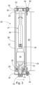
- FIGS 2b and 3 show the motor unit 26 for a fabric insertion unit in a fiber web machine.
- the motor unit 26 includes a hollow roll shell 27, which is the main part of the turning roll supporting the metal belt 28. Then there is a roll end 29 on both ends of the roll shell 27 as well as a bracket 30 for both roll ends 29. The roll end 29 is fixed to the roll shell 27 with bolts 31. Each bracket is bolted to the frame 20 with two screws 32.
- the motor unit 26 further includes bearings 33 on both ends of the roll shell 27 allowing the roll shell 27 to rotate in relation to the brackets 30. Then there is a motor 34 arranged inside the roll shell 27 and connected to the roll shell 27. With the motor the roll shell is rotated and thereby the metal belt is moved.
- the motor 34 is fixed to the bracket 30 non-rotatingly and the bearing 33 is an outer bearing 35 between the motor 34 and the roll end 29. In other words, the motor is stationary.
- the bearing 33 is an inner bearing 36 between the roll end 29 and the bracket 30.
- the outer bearing the outer ring rotates with the roll end while the inner ring is stationary.
- the inner bearing the inner ring rotates with the roll end while the outer ring is stationary.
- the motor 34 is connected to the opposite roll end 29 with an output shaft 37.
- the output shaft 37 is a spline shaft 38 plugged into an output axle 39 in the motor 34.
- the spline shaft adapts to thermal expansion and allows angular errors.
- the motor itself may be a standard motor, which reduces the manufacturing and maintenance costs.
- the motor 34 is equipped with a flanged shaft 40 as an extension fixed to the bracket 30.
- the flanged shaft 40 is a part of the motor 34 and supports the outer bearing 35.
- the flanged shaft 40 has supply conduits 41 for the motor 34. In this way, there are no pipes inside the motor unit prone to leak.
- the motor 34 is a standard hydraulic motor.
- the supply conduits 41 have couplings 42 for hydraulic supply.
- the diameter of the roll end 29 is larger than the diameter of the roll shell 27.
- the metal belt is prevented to slip of from the roll shell.
- the roll end acts as a guide.
- the turning roll are aligned in such way that the metal belt will stay in line without grinding against the roll end.
- each bracket is moved indirectly with one adjusting bolt 43.
- the bracket 30 has a slanting surface 44 for a key 45, which is attached to the frame 20 with said adjusting bolt 43.
- the key 45 has an adjusting bolt 43 having the same orientation as the roll shell 27.
- the adjusting bolt 43 is tightened, the key 45 moves towards the frame 20 and simultaneously stresses the brackets outwards, as shown in Figure 3 at the upper end.
- the adjustment bolt 43 is loosened, the key 45 comes out and the bracket 30 can move towards the frame 20. In this way, the metal belt 28 is loosened.
- the key 45 is two-sided.
- the frame has a corresponding slanting surface for the key.
- the key stays in line. With the key, a half of force is needed.
- the adjustment is gapless and stepless. Now the dimensions of the key determine the precision of the adjustment instead of the spiral rise of the adjustment bolt. This facilitates the aligning the turning roll.
- the angle of the key is 1 - 10 degrees since the displacement needed is only few millimeters. By changing the dimensions of the key the displacement of the bracket may be easily raised.
- the key 45 has different hardness than the bracket 30 or the key 45 is of different material than the bracket 30. In this way, the key will slide easily without any jamming.
- the key may be of, for example, brass, copper, or plastic, and it can also be coated.
- the bracket 30 has two attachment lugs 46 between which the slanting surface 44 is arranged.
- the key 45 is between the attachment lugs 46.
- the fabric insertion unit there are two or four motor units.
- the unit of Figure 2a has four motor units since there are hydraulic supplies in every turning roll.
- the motor unit according to the invention is also easy to retrofit.
- fabric insertion units now in use may be equipped with the motor units with stationary motors. Some minor amendments to the frame may be needed due the keys. Other fluid and hydraulic supplies can remain unchanged.
Landscapes
- Engineering & Computer Science (AREA)
- Mechanical Engineering (AREA)
- Treatment Of Fiber Materials (AREA)
- Paper (AREA)
Abstract
The invention relates to a motor unit for a fabric insertion unit in a fiber web machine. The motor unit (26) includes a hollow roll shell (27), and a roll end (29) on both ends of the roll shell (27), and a bracket (30) for both roll ends (29). The motor unit (26) further includes bearings (33) on both ends of the roll shell (27) allowing the roll shell (27) to rotate in relation to the brackets (30). Further, the motor unit (26) includes a motor (34) arranged inside the roll shell (27) and connected to the roll shell (27). At one end the motor (34) is fixed to the bracket (30) non-rotatingly, and the bearing (33) is an outer bearing (35) between the motor (34) and the roll end (29) while at the other end the bearing (33) is an inner bearing (36) between the roll end (29) and the bracket (30). The invention also relates a fabric insertion unit for a fiber web machine.
Description
- The present invention relates to a motor unit for a fabric insertion unit in a fiber web machine, the motor unit including
- a hollow roll shell,
- a roll end on both ends of the roll shell,
- a bracket for both roll ends,
- bearings on both ends of the roll shell allowing the roll shell to rotate in relation to the brackets, and
- a motor arranged inside the roll shell and connected to the roll shell. The invention relates also to fabric insertion unit for a fiber web machine.
- Chinese patent application number
CN108221451 discloses a fabric insertion unit, which is a device for changing a fabric in a fiber web machine. The fabric insertion unit includes two oppositely arranged transfer devices including lifting means. Each transfer device includes a frame having two roll shells supporting a metal belt arranged as a loop. The metal belt is moved by rotating one or both roll shells with a motor. While the opposite metal belts move is the fabric moved between them. In the known motor unit the motor inside of the roll shell rotates together with the roll shell. Before use, the metal belt is aligned and tightened by moving the bracket with one big or two smaller bolts in relation with the frame. Last, the bracket is fixed in place. - The known structure is complex, expensive, and difficult to manufacture and install. Especially, installing pipes through the end flange of the bracket is problematic due the rotation. A rotating connector is required, and the connector itself requires space, which must be considered in the surrounding structures. In addition, the structure has been found prone to leaking. One big bolt requires a lot of space like the tool itself. Still not enough force is achieved. With two smaller bolts only little force is achieved. It is also difficult to tighten the small bolts evenly. Uneven tightening will twist the bracket.
- The object of the invention is to provide a motor unit for a fabric insertion unit in a fiber web machine, which motor unit is more durable than before, and also easier and quicker to assemble and maintain. The characteristic features of the motor unit according to the invention are stated in the accompanying Claim 1. With new constructions, the rotating connector may be omitted, and there are less leak sensitive joints. Also, the assembly of the motor unit is easier, and the metal belt can be tightened with precise and reasonable force. Another object of the invention is to provide a new fabric insertion unit in a fiber web machine which is more reliable and easier to maintain than before. The characteristic features of the fabric insertion unit according to the invention are stated in the accompanying
Claim 12. The leakages of fluid and pressure may be avoided, and the functions of the fabric insertion unit can be easily amended, if needed. - The invention is described below in detail by referring to the enclosed drawings, which illustrate some of the embodiments of the invention, in which
- Figure 1
- shows an example of the body of the press section of a fiber web machine, viewed from the side,
- Figure 2a
- shows a complete fabric insertion unit to be attached to a fiber web machine,
- Figure 2b
- shows a vertical cross section of one motor unit according to the invention,
- Figure 3
- shows a horizontal cross section of another motor unit according to the invention.
-
Figure 1 shows an example of the press section of a fiber web machine, viewed from the tending side. The press section includes aframework 10, which hasseveral beam structures presses 13, each of which has twofabrics 14. Thefabrics 14 formed into endless loops are supported byrolls 15. The rolls are supported on theframework 10. From time to time, each fabric must be replaced. Fiber web machine refers to, for example, paper, cardboard and pulp machines and belt calenders with replaceable fabrics. Closed fabric loops include, for example, the wires on the web forming part and the felts and belts on the press section of the fiber web machine. - In the shown embodiment, several
fabric insertion units 16 are arranged in theframework 10 on the tending side. The fabric insertion units will later be referred to more simply as units. The unit is used to change the fabric on a web forming machine and the unit is intended to be installed in theframe 10 of the web forming machine.Figure 1 shows theunits 16 in principle. In addition to theunits 16, theframework 10 includesspacers 17, which are removed when changing thefabric 14. -
Figure 2a shows theunit 16 according to the invention detached from the framework of the fiber web machine. Theunit 16 includes two oppositely arrangedtransfer devices 18 for moving thefabric 14. In addition, the unit includes lifting means 19 for forming a transfer passage between thetransfer devices 18 for thefabric 14. In practice, the transfer passage enables the fabric to be taken through the framework of the fiber web machine. Furthermore, eachtransfer device 18 includes aframe 20 adapted as a part of the lifting means. Also, each frame is attached to the fiber web machine with plurality ofbolts 21. The lifting means function by pressurized fluid. For this, theframe 20 has internal channels for fluid equipped in the lifting means 19. Fluid is fed to the channels via aninlet 22 while fluid exit via anoutlet 23. Suitable pipes are attached to the inlets and the outlets when the unit is installed. - In
Figure 2a , theunit 16 is in the production position and thetransfer devices 18 are connected to each other on both edges with locking means 24, which here are eye bolts. The locking means prevent the mutual movement of the frames during production, keeping the frames together despite vibration and load. During the production, anintermediate structure 25 is between the frames, carrying the load from frame to frame. - When changing the fabric, the locking means 24 are loosened. Then, the distance between the transfer devices, more specifically the frames of the transfer device, is increased by using the lifting means. In practice, a sufficient lift is 0,5 - 10 mm. In this case, the frames are separated from each other, so that the
intermediate structure 25 can be removed. Thus, the transfer passage is formed between the frames, making it possible to transfer the fabric using the transfer devices. - As mentioned, the lifting means is arranged as part of the frame of the transfer device. More specifically, the lifting means includes a pressure chamber delimited by a pressure water seal in the frame. The seal has rounded rectangular perimeter, and it delimits the pressure chamber together with a metal belt loop supported by the turning rolls. The turning rolls are attached to the frame and there is a motor unit in one or more turning rolls.
- Advantageously, fluid, for example water, is fed into the pressure chamber, which at the same time lubricates the seals gliding against the metal belt without contaminating the environment. Both frames have the same kind of channels, and the lifting means function equally, as shown in
Figure 2a . -
Figures 2b and3 show themotor unit 26 for a fabric insertion unit in a fiber web machine. Themotor unit 26 includes ahollow roll shell 27, which is the main part of the turning roll supporting themetal belt 28. Then there is aroll end 29 on both ends of theroll shell 27 as well as abracket 30 for both roll ends 29. Theroll end 29 is fixed to theroll shell 27 withbolts 31. Each bracket is bolted to theframe 20 with twoscrews 32. Themotor unit 26 further includesbearings 33 on both ends of theroll shell 27 allowing theroll shell 27 to rotate in relation to thebrackets 30. Then there is amotor 34 arranged inside theroll shell 27 and connected to theroll shell 27. With the motor the roll shell is rotated and thereby the metal belt is moved. - According to the invention, at one end of the
roll shell 27 themotor 34 is fixed to thebracket 30 non-rotatingly and thebearing 33 is anouter bearing 35 between themotor 34 and theroll end 29. In other words, the motor is stationary. At the other of theroll shell 27 end thebearing 33 is aninner bearing 36 between theroll end 29 and thebracket 30. In the outer bearing, the outer ring rotates with the roll end while the inner ring is stationary. Correspondingly, in the inner bearing, the inner ring rotates with the roll end while the outer ring is stationary. With this construction, the known rotating connector is useless which reduces the likelihood of leaks. During the use, the motor stays in place while the roll shell rotates. The construction of the motor unit becomes simpler and cheaper than before. Also the manufacturing speeds up. In addition, errors in functionality are reduced and oil spills will be extremely rare. - The
motor 34 is connected to theopposite roll end 29 with anoutput shaft 37. Here theoutput shaft 37 is aspline shaft 38 plugged into anoutput axle 39 in themotor 34. The spline shaft adapts to thermal expansion and allows angular errors. The motor itself may be a standard motor, which reduces the manufacturing and maintenance costs. Here themotor 34 is equipped with aflanged shaft 40 as an extension fixed to thebracket 30. Theflanged shaft 40 is a part of themotor 34 and supports theouter bearing 35. In addition, theflanged shaft 40 hassupply conduits 41 for themotor 34. In this way, there are no pipes inside the motor unit prone to leak. As mentioned earlier, themotor 34 is a standard hydraulic motor. Thesupply conduits 41 have couplings 42 for hydraulic supply. - As shown in
Figure 2b the diameter of theroll end 29 is larger than the diameter of theroll shell 27. In this way, the metal belt is prevented to slip of from the roll shell. In other words, the roll end acts as a guide. However, in practice, the turning roll are aligned in such way that the metal belt will stay in line without grinding against the roll end. - Contrary the known technology, each bracket is moved indirectly with one adjusting
bolt 43. In practice, thebracket 30 has a slantingsurface 44 for a key 45, which is attached to theframe 20 with said adjustingbolt 43. Thereby less power is needed, and the adjustingbolt 43 is easily reached from the side of the frame. More precisely, the key 45 has an adjustingbolt 43 having the same orientation as theroll shell 27. When the adjustingbolt 43 is tightened, the key 45 moves towards theframe 20 and simultaneously stresses the brackets outwards, as shown inFigure 3 at the upper end. Respectively, when theadjustment bolt 43 is loosened, the key 45 comes out and thebracket 30 can move towards theframe 20. In this way, themetal belt 28 is loosened. - Advantageously, the key 45 is two-sided. In other words, also the frame has a corresponding slanting surface for the key. Thus the key stays in line. With the key, a half of force is needed.
- In practice, even one adjustment bolt is enough to tighten the metal belt enough. At the same time, the adjustment is gapless and stepless. Now the dimensions of the key determine the precision of the adjustment instead of the spiral rise of the adjustment bolt. This facilitates the aligning the turning roll. In practice, the angle of the key is 1 - 10 degrees since the displacement needed is only few millimeters. By changing the dimensions of the key the displacement of the bracket may be easily raised.
- Advantageously, the key 45 has different hardness than the
bracket 30 or the key 45 is of different material than thebracket 30. In this way, the key will slide easily without any jamming. The key may be of, for example, brass, copper, or plastic, and it can also be coated. - As shown in
Figure 2a , thebracket 30 has two attachment lugs 46 between which the slantingsurface 44 is arranged. In other words, the key 45 is between the attachment lugs 46. Thus, the bracket will move straight when the key is tightened. In this way, any misalignment of the bracket is prevented. - In the fabric insertion unit there are two or four motor units. The unit of
Figure 2a has four motor units since there are hydraulic supplies in every turning roll. The motor unit according to the invention is also easy to retrofit. Thus fabric insertion units now in use may be equipped with the motor units with stationary motors. Some minor amendments to the frame may be needed due the keys. Other fluid and hydraulic supplies can remain unchanged.
Claims (15)
- Motor unit for a fabric insertion unit in a fiber web machine, the motor unit (26) including- a hollow roll shell (27),- a roll end (29) on both ends of the roll shell (27),- a bracket (30) for both roll ends (29),- bearings (33) on both ends of the roll shell (27) allowing the roll shell (27) to rotate in relation to the brackets (30), and- a motor (34) arranged inside the roll shell (27) and connected to the roll shell (27),characterized in that at one end the motor (34) is fixed to the bracket (30) non-rotatingly and the bearing (33) is an outer bearing (35) between the motor (34) and the roll end (29) while at the other end the bearing (33) is an inner bearing (36) between the roll end (29) and the bracket (30).
- Motor unit according to claim 1, characterized in that the motor (34) is connected to the opposite roll end (29) with an output shaft (37).
- Motor unit according to claim 2, characterized in that the output shaft (37) is a spline shaft (38) plugged into an output axle (39) in the motor (34).
- Motor unit according to any of claims 1 - 3, characterized in that the motor (34) is equipped with a flanged shaft (40) as an extension fixed to the bracket (30).
- Motor unit according to claim 4, characterized in that the flanged shaft (40) has supply conduits (41) for the motor (34).
- Motor unit according to any of claims 1 - 5, characterized in that the motor (34) is a standard hydraulic motor.
- Motor unit according to any of claims 1 - 6, characterized in that the diameter of the roll end (29) is larger than the diameter of the roll shell (27).
- Motor unit according to any of claims 1 - 7, characterized in that the bracket (30) has a slanting surface (44) for a key (45).
- Motor unit according to claim 8, characterized in that the key (45) has different hardness than the bracket (30) or the key (45) is of different material than the bracket (30).
- Motor unit according to claim 8 or 9, characterized in that the key (45) is two-sided.
- Motor unit according to any of claims 8 - 10, characterized in that the bracket (30) has two attachment lugs (46) between which the slanting surface (44) is arranged.
- Fabric insertion unit for a fiber web machine, which unit (16) is arranged to be installed in a framework (10) of a fiber web machine, and which unit (16) includes two oppositely arranged transfer devices (18) for transferring a fabric (14) and including lifting means (19) for forming a transfer passage (20) between the transfer devices (18) for the fabric (14), wherein the transfer device has a frame (21) having one or two the motor units (26) each including- a hollow roll shell (27),- a roll end (29) on both ends of the roll shell (27),- a bracket (30) for both roll end (29),- bearings (33) on both ends of the roll shell (27) allowing the roll shell (27) to rotate in relation to the brackets (30), and- a motor (34) arranged inside the roll shell (27) and connected to the roll shell (27),characterized in that at one end the motor (34) is fixed to the bracket (30) non-rotatingly and the bearing (33) is an outer bearing (35) between the motor (34) and the roll end (29) while at the other end the bearing (33) is an inner bearing (36) between the roll end (29) and the bracket (30).
- Unit according to claim 12, characterized in that the motor unit (26) is a motor unit according to any of claims 2-11.
- Unit according to claim 12 or 13, characterized in that the bracket (30) is bolted to the frame (21) and there is a slanted key (45) between the bracket (30) and the frame (21).
- Unit according to any claim 14, characterized in that the key (45) has an adjusting bolt (43) having the same orientation as the roll shell (27).
Applications Claiming Priority (1)
| Application Number | Priority Date | Filing Date | Title |
|---|---|---|---|
| FI20235633A FI131016B1 (en) | 2023-06-07 | 2023-06-07 | Motor unit for a fabric insertion unit in a fiber web machine and fabric insertion unit for a fiber web machine |
Publications (1)
| Publication Number | Publication Date |
|---|---|
| EP4474316A1 true EP4474316A1 (en) | 2024-12-11 |
Family
ID=91274524
Family Applications (1)
| Application Number | Title | Priority Date | Filing Date |
|---|---|---|---|
| EP24177525.3A Pending EP4474316A1 (en) | 2023-06-07 | 2024-05-23 | Motor unit for a fabric insertion unit in a fiber web machine and fabric insertion unit for a fiber web machine |
Country Status (3)
| Country | Link |
|---|---|
| EP (1) | EP4474316A1 (en) |
| CN (1) | CN119100170A (en) |
| FI (1) | FI131016B1 (en) |
Citations (5)
| Publication number | Priority date | Publication date | Assignee | Title |
|---|---|---|---|---|
| US3494208A (en) * | 1968-08-21 | 1970-02-10 | Pettibone Mulliken Corp | Self-contained,fluid-driven pulley construction |
| US6125993A (en) * | 1997-10-28 | 2000-10-03 | Hansson; Ulf G. | Hydraulic roller |
| WO2006106178A1 (en) * | 2005-04-05 | 2006-10-12 | Metso Paper, Inc. | Method and device for changing a fabric in a paper or board machine |
| CN108221451A (en) | 2016-12-21 | 2018-06-29 | 维美德技术有限公司 | For replacing the equipment of the fabric in web forming machine |
| US10138068B2 (en) * | 2016-08-16 | 2018-11-27 | Tech-Roll Inc. | Powered roller systems and methods |
-
2023
- 2023-06-07 FI FI20235633A patent/FI131016B1/en active
-
2024
- 2024-05-23 EP EP24177525.3A patent/EP4474316A1/en active Pending
- 2024-06-06 CN CN202410730709.0A patent/CN119100170A/en active Pending
Patent Citations (5)
| Publication number | Priority date | Publication date | Assignee | Title |
|---|---|---|---|---|
| US3494208A (en) * | 1968-08-21 | 1970-02-10 | Pettibone Mulliken Corp | Self-contained,fluid-driven pulley construction |
| US6125993A (en) * | 1997-10-28 | 2000-10-03 | Hansson; Ulf G. | Hydraulic roller |
| WO2006106178A1 (en) * | 2005-04-05 | 2006-10-12 | Metso Paper, Inc. | Method and device for changing a fabric in a paper or board machine |
| US10138068B2 (en) * | 2016-08-16 | 2018-11-27 | Tech-Roll Inc. | Powered roller systems and methods |
| CN108221451A (en) | 2016-12-21 | 2018-06-29 | 维美德技术有限公司 | For replacing the equipment of the fabric in web forming machine |
Also Published As
| Publication number | Publication date |
|---|---|
| FI131016B1 (en) | 2024-08-01 |
| FI20235633A1 (en) | 2024-08-01 |
| CN119100170A (en) | 2024-12-10 |
Similar Documents
| Publication | Publication Date | Title |
|---|---|---|
| CN1024287C (en) | Press roll | |
| EP0527881B1 (en) | Press roll | |
| FI78136B (en) | ROTARY EQUIPMENT. | |
| US20090265947A1 (en) | Bearing Alignment Tool and Method Of Use | |
| CA1168687A (en) | Roll | |
| FI79058C (en) | PRESSCYLINDER FOER DJUPTRYCKSMASKIN. | |
| US11493122B2 (en) | Planetary gearing with improved lubricant supply, drive train and wind turbine | |
| RU1838490C (en) | Pressing roller with the regulated sagging | |
| US5246155A (en) | Air supported web guide roller with end seal covers | |
| US5533569A (en) | Stationary syphon system for rotating heat exchanger rolls | |
| US3766620A (en) | Controlled deflection roll drive | |
| US4582128A (en) | Rotating heat exchanger | |
| JP3105457B2 (en) | Roll-in roller unit for web rotary printing press | |
| US7004509B2 (en) | Journal bearing mounted hub seal rotary joint | |
| CN100434199C (en) | Spreader Roller | |
| FI131016B1 (en) | Motor unit for a fabric insertion unit in a fiber web machine and fabric insertion unit for a fiber web machine | |
| US4363615A (en) | Drivable roll of controllable flexure, particularly for machines for the production and processing of webs of paper or plastic | |
| US6796929B2 (en) | Self-adjusting deflection controlled roll | |
| JP4454334B2 (en) | roll | |
| KR100383525B1 (en) | Hydrostatic Cell Feeding Flexural Control Roll | |
| EP1220965B1 (en) | Calender | |
| GB2281921A (en) | Apparatus for producing single-faced corrugated board sheets | |
| EP1716287B1 (en) | Method and apparatus in conjunction with a shoe press | |
| EP4474571A2 (en) | Frame for a fabric insertion unit in a fiber web machine and fabric insertion unit for a fiber web machine | |
| US3481016A (en) | Driven controlled deflection roll |
Legal Events
| Date | Code | Title | Description |
|---|---|---|---|
| PUAI | Public reference made under article 153(3) epc to a published international application that has entered the european phase |
Free format text: ORIGINAL CODE: 0009012 |
|
| STAA | Information on the status of an ep patent application or granted ep patent |
Free format text: STATUS: THE APPLICATION HAS BEEN PUBLISHED |
|
| AK | Designated contracting states |
Kind code of ref document: A1 Designated state(s): AL AT BE BG CH CY CZ DE DK EE ES FI FR GB GR HR HU IE IS IT LI LT LU LV MC ME MK MT NL NO PL PT RO RS SE SI SK SM TR |
|
| STAA | Information on the status of an ep patent application or granted ep patent |
Free format text: STATUS: REQUEST FOR EXAMINATION WAS MADE |
|
| 17P | Request for examination filed |
Effective date: 20250606 |