EP4474301A1 - Method, device and system for labelling - Google Patents
Method, device and system for labelling Download PDFInfo
- Publication number
- EP4474301A1 EP4474301A1 EP23177733.5A EP23177733A EP4474301A1 EP 4474301 A1 EP4474301 A1 EP 4474301A1 EP 23177733 A EP23177733 A EP 23177733A EP 4474301 A1 EP4474301 A1 EP 4474301A1
- Authority
- EP
- European Patent Office
- Prior art keywords
- harness
- cable
- wire
- identification element
- identification
- Prior art date
- Legal status (The legal status is an assumption and is not a legal conclusion. Google has not performed a legal analysis and makes no representation as to the accuracy of the status listed.)
- Pending
Links
Images

Classifications
-
- B—PERFORMING OPERATIONS; TRANSPORTING
- B65—CONVEYING; PACKING; STORING; HANDLING THIN OR FILAMENTARY MATERIAL
- B65C—LABELLING OR TAGGING MACHINES, APPARATUS, OR PROCESSES
- B65C9/00—Details of labelling machines or apparatus
- B65C9/26—Devices for applying labels
- B65C9/36—Wipers; Pressers
-
- B—PERFORMING OPERATIONS; TRANSPORTING
- B65—CONVEYING; PACKING; STORING; HANDLING THIN OR FILAMENTARY MATERIAL
- B65C—LABELLING OR TAGGING MACHINES, APPARATUS, OR PROCESSES
- B65C3/00—Labelling other than flat surfaces
- B65C3/02—Affixing labels to elongated objects, e.g. wires, cables, bars, tubes
-
- B—PERFORMING OPERATIONS; TRANSPORTING
- B65—CONVEYING; PACKING; STORING; HANDLING THIN OR FILAMENTARY MATERIAL
- B65C—LABELLING OR TAGGING MACHINES, APPARATUS, OR PROCESSES
- B65C9/00—Details of labelling machines or apparatus
- B65C9/08—Label feeding
-
- B—PERFORMING OPERATIONS; TRANSPORTING
- B65—CONVEYING; PACKING; STORING; HANDLING THIN OR FILAMENTARY MATERIAL
- B65C—LABELLING OR TAGGING MACHINES, APPARATUS, OR PROCESSES
- B65C9/00—Details of labelling machines or apparatus
- B65C9/26—Devices for applying labels
-
- B—PERFORMING OPERATIONS; TRANSPORTING
- B65—CONVEYING; PACKING; STORING; HANDLING THIN OR FILAMENTARY MATERIAL
- B65C—LABELLING OR TAGGING MACHINES, APPARATUS, OR PROCESSES
- B65C9/00—Details of labelling machines or apparatus
- B65C9/40—Controls; Safety devices
- B65C9/42—Label feed control
-
- B—PERFORMING OPERATIONS; TRANSPORTING
- B65—CONVEYING; PACKING; STORING; HANDLING THIN OR FILAMENTARY MATERIAL
- B65C—LABELLING OR TAGGING MACHINES, APPARATUS, OR PROCESSES
- B65C9/00—Details of labelling machines or apparatus
- B65C9/46—Applying date marks, code marks, or the like, to the label during labelling
Definitions
- the present invention generally relates to a method for adhering an identification element to a cable, a wire or a harness. Particularly the present invention relates to a method wherein an identification element may be moved and adhered by means of a robot. The invention further relates to a device for picking up an identification element and folding the identification element to a cable, a wire or a harness. The invention further relates to a respective system for performing the method.
- the automotive sector is facing a shift towards electric vehicles. This is accompanied by an increasing number of electrical and electronic devices that need to be connected, which results in a rapid increase of electric cables, wires and/or harnesses to facilitate provision of electrical connections.
- cables, wires and/or harness are usually provided with labels so as to provide these parts with information. Further, the labels of a cable could be provided with a unique identification code to ensure that correct connections are made.
- Cables, wires and/or harnesses may alternatively be labelled off-site, e.g., by printing a label directly onto the cable, wire and/or harness. However, this reduces flexibility.
- An aspect of the invention relates to a method for adhering an identification element to a cable, a wire or a harness, the method comprising: providing an identification element to be adhered; moving the identification element by means of a robot to a cable, a wire, or a harness; adhering, using the robot, the moved identification element to the cable, the wire or the harness.
- the present disclosure provides an improved method for adhering an identification element to a cable, a wire or a harness.
- human errors may be mitigated and/or reduced.
- traceability can be improved, since moving the identification element by means of a robot can be predicted upfront and/or scheduled. This may also aid in optimizing adhering the identification element.
- cycle times can be reduced.
- a cycle time may be understood as the time needed for picking up the identification element, moving the identification element to a cable, a wire, or a harness and adhering the moved identification element to the cable, the wire or the harness.
- the overall method allows for adhering the identification element in a more cost-effective manner.
- providing the identification element can be substantially synchronized with the cable, wire, or harness being produced. Extensive labor can be reduced, as the method may be substantially automated. Hence, moving and adhering the identification element may not require any controlling and/or checking of an operator. Thereby, an operator may conduct other tasks while the inventive method is performed substantially automatically. Further, as manual labor may be substantially dispensed with, injuries occurring for instance by way of repetitive motions performed by operators can be reduced.
- the method has the further advantage that the adhering can be carried out several times with essentially the same conditions. Thereby, the method steps may be performed substantially in a predetermined and/or automated manner. In turn, the method is substantially standardized and may be reproducible.
- the identification element may be a label, such as a self-adhesive label.
- the identification element may comprise one or more indicia.
- the identification element may comprise one or more identification codes, which could be printed onto the identification element.
- the indicia and/or identification code may be one or more of a one/two-dimensional code, such as a QR code, a bar code, an indication of a direction of the cable, wire or harness, an indication of properties of electronic components connected by the cable, wire or harness, as described elsewhere herein.
- the cable, wire or harness could be part of an electrical vehicle and used for connecting electrical components.
- Providing may be understood such that the identification element is made available for being picked up.
- Providing may optionally comprise printing an identification code and/or an indicia onto the identification element.
- the identification element bridges a distance. This may be performed in a fast and flexible manner attributable to the robot.
- the robot may be understood as any means that could work automatically and/or that could be controlled by a computer.
- the robot may be a mechanical device. This may aid in ensuring that moving and adhering can be performed in an economic manner so as to reduced errors.
- Adhering may be understood such that the identification element is substantially fixed to the cable, wire or harness.
- the method may be substantially automated and/or the method steps may be performed substantially continuously.
- the method comprises picking up the provided identification element, using the robot, preferably by using a suction nozzle comprised by the robot to substantially hold the identification element.
- Picking up the provided identification element may comprise grabbing the provided identification element.
- the suction nozzle may be understood as a low vacuum applicator.
- the suction nozzle has the advantage that the identification element is held by the robot in a substantially fixed manner. Thereby, the robot can perform any movements, without impairing the identification element. In particular, fast movements may thereby be performed.
- moving comprises a three-dimensional movement, preferably a rotation about one, two or three substantially orthogonal axes, and/or a translation along one, two or three substantially orthogonal axes.
- moving comprises moving the identification element about a distance of at least 5 cm, preferably at least 10 cm, preferably at least 20 cm, preferably at least 30 cm, preferably at least 40 cm, preferably at least 50 cm, preferably at least 60 cm, preferably at least 80 cm, preferably at least 100 cm.
- moving comprises moving the identification element about a distance of at most 200 cm, preferably at most 180 cm, preferably at most 160 cm, preferably at most 140 cm, preferably at most 120 cm, preferably at most 100 cm.
- moving comprises rotating the identification element about an angle of at least 10°, preferably at least 20°, preferably at least 50°, preferably at least 100°, preferably at least 180°, preferably at least 360°.
- moving comprises a translation and/or rotation in a repetitive manner, preferably by a predefined pattern.
- the pattern may be stored in a computer-readable storage medium.
- the pattern may be determined based on use cases of an identification element of the past.
- moving is performed in a time of at most 20 seconds, preferably at most 15 seconds, preferably at most 10 seconds, preferably at most 8 seconds, preferably at most 6 seconds, preferably at most 4 seconds, most preferably at most 3 seconds.
- the movements as described herein have the advantage that adhering the identification element can be improved and can be made more cost-effective.
- the movement can thereby be optimized and adjusted according to the use case and/or the arrangement of cables, wires or harnesses.
- adhering comprises gluing the identification element to the cable, wire or harness at least partially by means of an adhesive.
- any kind of gluing may be used so as to fixedly attach the identification element to the cable, wire or harness.
- the adhesive may be provided by means of an external adhesive and/or an adhesive already provided by the identification element.
- the identification element is a self-adhesive label comprising one or more indicia, wherein, optionally, adhering comprises folding the label at least partially around the cable, wire or harness.
- the indicia may be indicative of any sign, picture, logo, or the like that could be related to the cable, wire or harness. For instance, it may aid in identifying electronic components that are connected by way of the cable, wire or harness.
- the indicia may comprise one or more colors.
- folding the label is performed such that the edges of the folded label are substantially on top of one another.
- substantially the overall surface of the label can be used for adhering two halves of the label to one another. This makes adhesion more effective.
- the cable, wire or harness may be arranged at substantially the middle of the label such that the final configuration of the label after folding about the cable, wire or harness adopts a flag-shape.
- This also provides for an increased surface area of the label that could be used for indicia and/or identification codes as described elsewhere herein.
- providing comprises printing an identification code onto the identification element using a printer and/or storing the identification element on a roll or stack of elements.
- the identification code may comprise letters and/or other elements indicative of characteristics of electronic components, dates or the like.
- the identification code is one or more of the following: a two-dimensional code, such as a QR code; a one-dimensional code, such as a bar code; an indication of a direction of the cable, wire or harness; an indication of electronic components connected by the cable, wire or harness; an indication of the width, length, diameter, voltage of the cable, wire or harness; an indication of the production date and/or time of the cable, wire or harness; an indication of the machine ID used for the production of the cable, wire or harness.
- a two-dimensional code such as a QR code
- a one-dimensional code such as a bar code
- an indication of a direction of the cable, wire or harness an indication of electronic components connected by the cable, wire or harness
- an indication of the width, length, diameter, voltage of the cable, wire or harness an indication of the production date and/or time of the cable, wire or harness
- an indication of the machine ID used for the production of the cable, wire or harness is one or more of the following: a two-dimensional code, such as a QR
- the indicia and/or the identification code may be combined in an arbitrary manner. This improves recognizing the identification label and/or distinguishing one identification label from others.
- a further aspect of the invention relates to a device for picking up an identification element and folding the identification element to a cable, a wire or a harness, preferably the device being for use in the method as described elsewhere herein, wherein the device comprises: two holders configured to be rotated and translated to fold an identification element at least partially around a cable, wire or harness; wherein the holders are each provided with at least one suction nozzle at a downward side of the holder to substantially hold an identification element.
- the device may be specifically adapted to be used in the method as described herein.
- the device may be adapted to be used for one or more method steps as described herein.
- the device facilitates picking up the provided identification element and folding the identification element in a substantially automated fashion. Hence, operator's participation may be reduced.
- the device may not be necessarily part of a robot as described herein.
- the device can be used as a substantially stationary device, whereas a cable, wire, or harness is moved in proximity to the device so as to perform the folding and adhering of the identification element to the cable, wire or harness.
- the device is provided as part of a robot so as to automate picking up, moving, folding, and adhering as described elsewhere herein.
- the cable, wire or harness may be arranged substantially in the middle of the identification element, before the identification element is at least partially folded around the cable, wire or harness.
- the at least one suction nozzle may provide a pressure difference such that the pressure in the inside of the two holders is lower than outside of the two holders.
- the pressure may be reduced so as to provide substantially a vacuum. This has the advantage that a sufficient force acts on the identification element.
- the reduced pressure is substantially identical in any suction nozzle.
- This has the advantage that the pressure is substantially homogeneously.
- the force acting on the identification element is likewise homogeneously.
- substantially no local peaks of stresses may occur on the identification element.
- the at least one suction nozzle may also be configured to release the identification element.
- releasing comprises reducing the pressure difference between the inside of the holders and the outside. This may be achieved by releasing the vacuum. This may have the advantage that the process can be easily automated. As the pressure inside the two holders may be lower than ambient pressure, a valve or the like may be simply opened so as to allow ambient air to enter for releasing.
- the downward side may typically face an identification element during ordinary use of the device and when the identification element is picked up.
- the downward side typically faces the ground when the identification element is about to be picked up. It is understood that, when the device is rotated or the like, the downward side may face upwards, i.e., in a direction opposite to the ground, and/or in any other direction.
- the two holders have a substantially cuboid shape, which may optionally be provided with a recess as described elsewhere herein. In this manner, the two holders may provide sufficient support and structural integrity for the identification label to be moved or the like.
- Rotation and translation of the two holders ensures an efficient mechanism of movement for folding the identification element.
- the device is cost-effective and requires less service intervals.
- each holder is provided with four suction nozzles forming four corners of a rectangle, wherein the rectangle is arranged at a region of the downward side in proximity of the pivot axes of the support element.
- the reduced pressure inside the holders may act substantially homogeneously on the identification element, which ensures that the identification element is not exposed to adverse mechanical impacts, whilst it is firmly held.
- the two holders are configured to be in a first state in which the two downward sides of the two holders are arranged in one plane, and wherein the two holders are configured to be in a second state in which the two downward sides of the two holders are arranged substantially parallel and opposite to one another.
- the translation and rotation of the two holders allow for several intermediate states between the first state and the second state.
- the first state improves picking up the identification element, as the surface area for suction is increased.
- the device further comprises a support element having a central axis and two arm elements, each arm element being slidingly coupled to the support element on opposing sides of the support element and pivotably coupled to the two holders respectively, wherein the two holders are each pivotably coupled to a respective pivot axis disposed on the support element.
- the support element may be arranged in a central position with respect to an identification element when picked up.
- the two holders may be arranged at an outer side, e.g., further away from the central position.
- At least a part of each arm element may be configured so as to move substantially in parallel to the central axis of the support element. For instance, this may be achieved by way of a guiding rail arranged on the support element, which determines the movement of the part of each arm element.
- the support element comprises two pivot axes.
- the distance between the two pivot axes may substantially correspond to a dimension, such as a diameter of a cable, wire or harness.
- each arm element being slidingly coupled to the support element is configured to move in a direction substantially parallel to the central axis of the support element and thereby configured to trigger a rotational movement of each of the holders about each pivot axis respectively.
- each arm element comprises two end portions.
- the end portions may be understood as a small region in proximity to the end of each arm element. Since each arm element is pivotably coupled to a respective holder, a rotational movement may be triggered. This ensures an improved mechanism of movement of the two holders.
- the two pivot axes of the support element are arranged closer to the central axis of the support element compared to the end portion of each arm element being pivotably coupled to the respective holder.
- This may provide for triggering of a rotation of the two holders by way of the translational movement of the end portions of the arm elements that are slidingly coupled to the support element.
- the distance between the two pivot axes and the end portion of each arm element being pivotably coupled to the respective holder allows to adjust the rotational movement of each of the two holders.
- each arm element being pivotably coupled to the respective holder is directed away with respect to the central axis of the support element.
- each holder comprises a recess on a side of the holder opposite to the downward side of the holder, wherein the recess accommodates an L-shaped lever comprised by the device, the lever being pivotably coupled to the respective pivot axis of the support element and being pivotably coupled to the respective arm element.
- the L-shaped lever has the advantage to couple each arm element and each holder to the support element. This increases the mechanical integrity.
- each arm element being pivotably coupled to the respective holder is arranged on a side of each holder opposite to the downward side of each holder.
- a further aspect of the invention relates a system for carrying out the method as described herein, comprising: a device for picking up an identification element and folding the identification element to a cable, a wire or a harness as described herein; a robot comprising a movable arm for carrying out three-dimensional movements; optionally a printer, for printing an identification code on to the identification element; wherein the device is arranged on the movable arm of the robot.
- Fig. 1 illustrates a device 5, system 1000 and exemplary method steps according to an embodiment of the invention.
- Fig. 1A shows the device 5 and system 1000 in a method step similar to the one of Fig. 2 , i.e., a method step in which no identification element 2 is held by the device 5.
- Fig. 1B shows the device 5 and system 1000 in a method step in which an identification element 2 is provided, e.g., by way of a printer 1020. Further, the device 5 may be about to pick up the identification element 2. The device 5 may be arranged on a robot arm 1010 of a robot. In Fig. 1C , the identification element 2 is picked up. In Fig. 1D , the identification element 2 has been moved to a cable, a wire or a harness 1.
- the device 5 is partially folded such that the identification element 2 is about to be adhered to the cable, wire or harness 1.
- adhering may be established in one example by way of an adhesive.
- the identification element 2 may be a self-adhesive label.
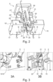
- Fig. 2 illustrates the device 5 of Fig. 1 in greater detail in a method step.
- the method step could be the step in which no identification element 2 is held by the device 5.
- the device 5 could be for use in the method as described herein.
- the device 5 comprises two holders 10, 10' configured to be rotated and translated to fold an identification element 2 (as best seen in Fig. 1 ) at least partially around a cable, wire or harness 1 (as best seen in Fig. 1 ).
- the two holders 10, 10' are each provided with at least one suction nozzle 12, 12' at a downward side 11, 11' of the two holders 10, 10'. This may ensure that the identification element 2 can be held firmly. This supports moving the identification element 2.
- the two holders 10, 10' are configured to be in a first state, in which the two downward sides 11, 11' of the two holders 10, 10' are arranged in one plane.
- Fig. 2 shows the device 5 in such a first state.
- the two holders 10, 10' are further configured to be in a second state, in which the two downward sides 11, 11' of the two holders 10, 10' are arranged substantially parallel and opposite to one another.
- the second state may be best seen in Fig. 3B .
- the device 5 can comprise a support element 30 having a central axis C and the device 5 can comprise two arm elements 20, 20'.
- Each arm element 20, 20' may be slidingly coupled to the support element 30 on opposing sides of the support element 30 and pivotably coupled to the two holders 10, 10' respectively.
- the two holders 10, 10' are each pivotably coupled to a respective pivot axis P disposed on the support element 30.
- each holder 10, 10' can be provided with four suction nozzles 12, 12' resembling four corners of a rectangle, wherein the rectangle is arranged at a region of the downward side 11, 11' in proximity of the pivot axes P of the support element 30.
- the two holders 10, 10' may be arranged substantially symmetrically with respect to the central axis C and at a position further away from the central position of the support element 30.
- each arm element 20, 20' can be configured so as to move substantially in parallel to the central axis C of the support element 30.
- the support element 30 may comprise two pivot axes P.
- the distance between the two pivot axes P in the plane through both downward sides 11, 11' may substantially correspond to a diameter of a cable, a wire or a harness 1.
- each arm element 20, 20' being slidingly coupled to the support element 30 is configured to move in a direction substantially parallel to the central axis C of the support element 30. Thereby, each arm element 20, 20' may trigger a rotational movement of each of the holders 10, 10' about each pivot axis P respectively.
- the two pivot axes P of the support element 30 are arranged closer to the central axis C of the support element 30 compared to the end portion 22, 22' of each arm element 20, 20' being pivotably coupled to the respective holder 10, 10'. As can be seen, the end portion 22, 22' of each arm element 20, 20' being pivotably coupled to the respective holder 10, 10' is directed away from the central axis C of the support element 30.
- Each holder 10, 10' may comprise a recess 15 (as best seen in Fig. 3B ) on a side of the holder 10, 10' opposite to the downward side 11, 11' of the holder 10, 10'.
- the recess 15 accommodates an L-shaped lever 25, 25' of the device 5.
- Each one of the levers 25, 25' are pivotably coupled to the respective pivot axis P of the support element 30 and are pivotably coupled to the respective arm element 25, 25'.
- each arm element 25, 25' being pivotably coupled to the respective holder 10, 10' is arranged on a side of each holder 10, 10' opposite to the downward side 11, 11' of each holder.
- Fig. 3 illustrates the device of Fig. 1 in another method step.
- the identification element 2 may be about to be adhered to the cable, wire or harness 1.
- Fig. 3A shows the device 5 arranged on a robot arm 1010.
- Fig. 3B shows the device 5 in the second state. In this second state, the two downward sides 11, 11' of the two holders 10, 10' are arranged substantially parallel and opposite to one another (one holder 10 can be seen in this Fig., the opposing holder 10' is on the backside of and hidden by the identification element 2).
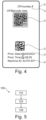
- Fig. 4 illustrates an identification element 2 according to an embodiment of the invention.
- the identification element 2 can comprise indicia 3 and/or identification code(s) 3.
- the indicia 3 can comprise colors or the like and may be indicative of any sign, picture, logo or the like that could be related to the cable, wire or harness and or the electronic components to be connected by way of the cable, wire or harness.
- the identification code 3 can be one or more of the following: a two-dimensional code, such as a QR code; a one-dimensional code, such as a bar code; an indication of a direction of the cable, wire or harness, an indication of electronic components connected by the cable, wire or harness, an indication of the width, length, diameter, voltage of the cable, wire or harness; an indication of the production date and/or time of the cable, wire or harness, and an indication of the machine ID used for the production of the cable, wire or harness.
- a two-dimensional code such as a QR code
- a one-dimensional code such as a bar code
- an indication of a direction of the cable, wire or harness an indication of electronic components connected by the cable, wire or harness, an indication of the width, length, diameter, voltage of the cable, wire or harness
- an indication of the production date and/or time of the cable, wire or harness an indication of the machine ID used for the production of the cable, wire or harness.
- Fig. 5 illustrates a flow chart of a method 100 for adhering an identification element to a cable, a wire or a harness according to an embodiment of the invention.
- the method 100 comprises: providing 110 an identification element to be adhered; moving 120 the identification element by means of a robot to a cable, a wire, or a harness; adhering 130, using the robot, the moved identification element to the cable, the wire or the harness.
- the method 100 comprises picking up the provided identification element, using the robot, preferably by using a suction nozzle comprised by the robot or by a device for picking up an identification element and folding the identification element as described elsewhere herein to substantially hold the identification element.
Landscapes
- Labeling Devices (AREA)
Abstract
The present disclose relates to a method (100) for adhering an identification element (2) to a cable, a wire or a harness (1), the method comprising: providing (110) an identification element (2) to be adhered; moving (120) the identification element (2) by means of a robot to a cable, a wire, or a harness (1); adhering (130), using the robot, the moved identification element (2) to the cable, the wire or the harness (1).
Description
- The present invention generally relates to a method for adhering an identification element to a cable, a wire or a harness. Particularly the present invention relates to a method wherein an identification element may be moved and adhered by means of a robot. The invention further relates to a device for picking up an identification element and folding the identification element to a cable, a wire or a harness. The invention further relates to a respective system for performing the method.
- The automotive sector is facing a shift towards electric vehicles. This is accompanied by an increasing number of electrical and electronic devices that need to be connected, which results in a rapid increase of electric cables, wires and/or harnesses to facilitate provision of electrical connections. Such cables, wires and/or harness are usually provided with labels so as to provide these parts with information. Further, the labels of a cable could be provided with a unique identification code to ensure that correct connections are made.
- In current practices the labelling of cables is typically performed by applying the label manually. However, such practices have several drawbacks.
- Typically, there are multiple cables that need to be labelled and the labelling is a complex and time-consuming process. This increases costs and poses difficulties for the labelling. Further, manual labelling is usually prone to human errors. Such errors can lead to issues in the labelling and/or manufacturing or installation of cables, wires and/or harnesses. Further disadvantages of manual labelling is that repetitive motions can cause injuries.
- Cables, wires and/or harnesses may alternatively be labelled off-site, e.g., by printing a label directly onto the cable, wire and/or harness. However, this reduces flexibility.
- In view of the foregoing, there is a need for improvement.
- It is thus an object of the present invention to overcome some or all of the deficiencies of the prior art. In particular, it is an object of the invention to provide an improved method for adhering an identification element to a cable, a wire or a harness.
- It is a further object to provide a device for picking up an identification element and folding the identification element to a cable, a wire or a harness.
- The above-mentioned objects are at least partially achieved by the subject-matter of the independent claims. Preferred embodiments are subject of the dependent claims, and the skilled person finds hints for other suitable aspects of the present invention through the overall disclosure of the present application.
- An aspect of the invention relates to a method for adhering an identification element to a cable, a wire or a harness, the method comprising: providing an identification element to be adhered; moving the identification element by means of a robot to a cable, a wire, or a harness; adhering, using the robot, the moved identification element to the cable, the wire or the harness.
- In this manner, the present disclosure provides an improved method for adhering an identification element to a cable, a wire or a harness. In particular, human errors may be mitigated and/or reduced. Further, traceability can be improved, since moving the identification element by means of a robot can be predicted upfront and/or scheduled. This may also aid in optimizing adhering the identification element. Moreover, cycle times can be reduced. A cycle time may be understood as the time needed for picking up the identification element, moving the identification element to a cable, a wire, or a harness and adhering the moved identification element to the cable, the wire or the harness.
- The overall method allows for adhering the identification element in a more cost-effective manner. In addition, providing the identification element can be substantially synchronized with the cable, wire, or harness being produced. Extensive labor can be reduced, as the method may be substantially automated. Hence, moving and adhering the identification element may not require any controlling and/or checking of an operator. Thereby, an operator may conduct other tasks while the inventive method is performed substantially automatically. Further, as manual labor may be substantially dispensed with, injuries occurring for instance by way of repetitive motions performed by operators can be reduced.
- The method has the further advantage that the adhering can be carried out several times with essentially the same conditions. Thereby, the method steps may be performed substantially in a predetermined and/or automated manner. In turn, the method is substantially standardized and may be reproducible.
- The identification element may be a label, such as a self-adhesive label. The identification element may comprise one or more indicia. The identification element may comprise one or more identification codes, which could be printed onto the identification element. The indicia and/or identification code may be one or more of a one/two-dimensional code, such as a QR code, a bar code, an indication of a direction of the cable, wire or harness, an indication of properties of electronic components connected by the cable, wire or harness, as described elsewhere herein.
- The cable, wire or harness could be part of an electrical vehicle and used for connecting electrical components.
- Providing may be understood such that the identification element is made available for being picked up. Providing may optionally comprise printing an identification code and/or an indicia onto the identification element.
- Moving may be understood such that the identification element bridges a distance. This may be performed in a fast and flexible manner attributable to the robot.
- The robot may be understood as any means that could work automatically and/or that could be controlled by a computer. The robot may be a mechanical device. This may aid in ensuring that moving and adhering can be performed in an economic manner so as to reduced errors.
- Adhering may be understood such that the identification element is substantially fixed to the cable, wire or harness.
- The method may be substantially automated and/or the method steps may be performed substantially continuously.
- In a preferred embodiment of the method as described herein, the method comprises picking up the provided identification element, using the robot, preferably by using a suction nozzle comprised by the robot to substantially hold the identification element.
- Picking up the provided identification element may comprise grabbing the provided identification element. The suction nozzle may be understood as a low vacuum applicator. The suction nozzle has the advantage that the identification element is held by the robot in a substantially fixed manner. Thereby, the robot can perform any movements, without impairing the identification element. In particular, fast movements may thereby be performed.
- In a preferred embodiment of the method as described herein, moving comprises a three-dimensional movement, preferably a rotation about one, two or three substantially orthogonal axes, and/or a translation along one, two or three substantially orthogonal axes.
- This has the advantage that any location can be reached by the robot. Thereby, the identification element may be moved to any desired location. This makes the method more flexible.
- Preferably, moving comprises moving the identification element about a distance of at least 5 cm, preferably at least 10 cm, preferably at least 20 cm, preferably at least 30 cm, preferably at least 40 cm, preferably at least 50 cm, preferably at least 60 cm, preferably at least 80 cm, preferably at least 100 cm.
- Preferably, moving comprises moving the identification element about a distance of at most 200 cm, preferably at most 180 cm, preferably at most 160 cm, preferably at most 140 cm, preferably at most 120 cm, preferably at most 100 cm.
- Preferably, moving comprises rotating the identification element about an angle of at least 10°, preferably at least 20°, preferably at least 50°, preferably at least 100°, preferably at least 180°, preferably at least 360°.
- Preferably, moving comprises a translation and/or rotation in a repetitive manner, preferably by a predefined pattern. The pattern may be stored in a computer-readable storage medium. The pattern may be determined based on use cases of an identification element of the past.
- Preferably, moving is performed in a time of at most 20 seconds, preferably at most 15 seconds, preferably at most 10 seconds, preferably at most 8 seconds, preferably at most 6 seconds, preferably at most 4 seconds, most preferably at most 3 seconds.
- The movements as described herein have the advantage that adhering the identification element can be improved and can be made more cost-effective. In particular, the movement can thereby be optimized and adjusted according to the use case and/or the arrangement of cables, wires or harnesses.
- In a preferred embodiment of the method as described herein, adhering comprises gluing the identification element to the cable, wire or harness at least partially by means of an adhesive.
- This has the advantage that the identification element can be fixedly and reliably attached to the cable, wire or harness for a prolonged time.
- Any kind of gluing may be used so as to fixedly attach the identification element to the cable, wire or harness. The adhesive may be provided by means of an external adhesive and/or an adhesive already provided by the identification element.
- In a preferred embodiment of the method as described herein, the identification element is a self-adhesive label comprising one or more indicia, wherein, optionally, adhering comprises folding the label at least partially around the cable, wire or harness.
- The indicia may be indicative of any sign, picture, logo, or the like that could be related to the cable, wire or harness. For instance, it may aid in identifying electronic components that are connected by way of the cable, wire or harness. The indicia may comprise one or more colors.
- In a preferred embodiment of the method as described herein, folding the label is performed such that the edges of the folded label are substantially on top of one another.
- This may ensure that substantially no adhesive of the self-adhesive label is left and exposed to the environment. This improves a reliable adhesion. Further, substantially the overall surface of the label can be used for adhering two halves of the label to one another. This makes adhesion more effective.
- In particular, the cable, wire or harness may be arranged at substantially the middle of the label such that the final configuration of the label after folding about the cable, wire or harness adopts a flag-shape. This also provides for an increased surface area of the label that could be used for indicia and/or identification codes as described elsewhere herein.
- In a preferred embodiment of the method as described herein, providing comprises printing an identification code onto the identification element using a printer and/or storing the identification element on a roll or stack of elements.
- The identification code may comprise letters and/or other elements indicative of characteristics of electronic components, dates or the like.
- In a preferred embodiment of the method as described herein, the identification code is one or more of the following: a two-dimensional code, such as a QR code; a one-dimensional code, such as a bar code; an indication of a direction of the cable, wire or harness; an indication of electronic components connected by the cable, wire or harness; an indication of the width, length, diameter, voltage of the cable, wire or harness; an indication of the production date and/or time of the cable, wire or harness; an indication of the machine ID used for the production of the cable, wire or harness.
- The indicia and/or the identification code may be combined in an arbitrary manner. This improves recognizing the identification label and/or distinguishing one identification label from others.
- A further aspect of the invention relates to a device for picking up an identification element and folding the identification element to a cable, a wire or a harness, preferably the device being for use in the method as described elsewhere herein, wherein the device comprises: two holders configured to be rotated and translated to fold an identification element at least partially around a cable, wire or harness; wherein the holders are each provided with at least one suction nozzle at a downward side of the holder to substantially hold an identification element.
- Since the method for adhering an identification element to a cable, a wire or a harness and the device for picking up an identification element and folding the identification element to a cable, a wire or a harness both relate to identification elements, it will be understood that advantages and/or features of the method may also apply to the device and vice versa.
- The device may be specifically adapted to be used in the method as described herein. In particular, the device may be adapted to be used for one or more method steps as described herein. The device facilitates picking up the provided identification element and folding the identification element in a substantially automated fashion. Hence, operator's participation may be reduced.
- It is understood that the device may not be necessarily part of a robot as described herein. For instance, the device can be used as a substantially stationary device, whereas a cable, wire, or harness is moved in proximity to the device so as to perform the folding and adhering of the identification element to the cable, wire or harness. Further, it may be possible to move the device manually in proximity to a cable, wire or harness. This can be done by manual work of an operator. Moreover, it may be possible that the device is provided as part of a robot so as to automate picking up, moving, folding, and adhering as described elsewhere herein.
- The cable, wire or harness may be arranged substantially in the middle of the identification element, before the identification element is at least partially folded around the cable, wire or harness.
- The at least one suction nozzle may provide a pressure difference such that the pressure in the inside of the two holders is lower than outside of the two holders. In one example, the pressure may be reduced so as to provide substantially a vacuum. This has the advantage that a sufficient force acts on the identification element.
- Preferably, the reduced pressure is substantially identical in any suction nozzle. This has the advantage that the pressure is substantially homogeneously. Thereby, the force acting on the identification element is likewise homogeneously. Thus, substantially no local peaks of stresses may occur on the identification element.
- The at least one suction nozzle may also be configured to release the identification element. Preferably, releasing comprises reducing the pressure difference between the inside of the holders and the outside. This may be achieved by releasing the vacuum. This may have the advantage that the process can be easily automated. As the pressure inside the two holders may be lower than ambient pressure, a valve or the like may be simply opened so as to allow ambient air to enter for releasing.
- The downward side may typically face an identification element during ordinary use of the device and when the identification element is picked up. The downward side typically faces the ground when the identification element is about to be picked up. It is understood that, when the device is rotated or the like, the downward side may face upwards, i.e., in a direction opposite to the ground, and/or in any other direction.
- The two holders have a substantially cuboid shape, which may optionally be provided with a recess as described elsewhere herein. In this manner, the two holders may provide sufficient support and structural integrity for the identification label to be moved or the like.
- Rotation and translation of the two holders ensures an efficient mechanism of movement for folding the identification element. Hence, the device is cost-effective and requires less service intervals.
- In a preferred embodiment of the device as described herein, the downward side of each holder is provided with four suction nozzles forming four corners of a rectangle, wherein the rectangle is arranged at a region of the downward side in proximity of the pivot axes of the support element.
- This improves that the identification element can be picked up in a reliable manner. In addition, the reduced pressure inside the holders may act substantially homogeneously on the identification element, which ensures that the identification element is not exposed to adverse mechanical impacts, whilst it is firmly held.
- In a preferred embodiment of the device as described herein, the two holders are configured to be in a first state in which the two downward sides of the two holders are arranged in one plane, and wherein the two holders are configured to be in a second state in which the two downward sides of the two holders are arranged substantially parallel and opposite to one another.
- It is understood that the translation and rotation of the two holders allow for several intermediate states between the first state and the second state. The first state improves picking up the identification element, as the surface area for suction is increased.
- In a preferred embodiment of the device as described herein, the device further comprises a support element having a central axis and two arm elements, each arm element being slidingly coupled to the support element on opposing sides of the support element and pivotably coupled to the two holders respectively, wherein the two holders are each pivotably coupled to a respective pivot axis disposed on the support element.
- The support element may be arranged in a central position with respect to an identification element when picked up. The two holders may be arranged at an outer side, e.g., further away from the central position.
- At least a part of each arm element may be configured so as to move substantially in parallel to the central axis of the support element. For instance, this may be achieved by way of a guiding rail arranged on the support element, which determines the movement of the part of each arm element.
- It is understood that the support element comprises two pivot axes. The distance between the two pivot axes may substantially correspond to a dimension, such as a diameter of a cable, wire or harness.
- In a preferred embodiment of the device as described herein, the end portion of each arm element being slidingly coupled to the support element is configured to move in a direction substantially parallel to the central axis of the support element and thereby configured to trigger a rotational movement of each of the holders about each pivot axis respectively.
- It is understood that each arm element comprises two end portions. The end portions may be understood as a small region in proximity to the end of each arm element. Since each arm element is pivotably coupled to a respective holder, a rotational movement may be triggered. This ensures an improved mechanism of movement of the two holders.
- In a preferred embodiment of the device as described herein, the two pivot axes of the support element are arranged closer to the central axis of the support element compared to the end portion of each arm element being pivotably coupled to the respective holder.
- This may provide for triggering of a rotation of the two holders by way of the translational movement of the end portions of the arm elements that are slidingly coupled to the support element. The distance between the two pivot axes and the end portion of each arm element being pivotably coupled to the respective holder allows to adjust the rotational movement of each of the two holders.
- It is understood that the end portion of each arm element being pivotably coupled to the respective holder is directed away with respect to the central axis of the support element.
- In a preferred embodiment of the device as described herein, each holder comprises a recess on a side of the holder opposite to the downward side of the holder, wherein the recess accommodates an L-shaped lever comprised by the device, the lever being pivotably coupled to the respective pivot axis of the support element and being pivotably coupled to the respective arm element.
- The L-shaped lever has the advantage to couple each arm element and each holder to the support element. This increases the mechanical integrity.
- In a preferred embodiment of the device as described herein, the end portion of each arm element being pivotably coupled to the respective holder is arranged on a side of each holder opposite to the downward side of each holder.
- A further aspect of the invention relates a system for carrying out the method as described herein, comprising: a device for picking up an identification element and folding the identification element to a cable, a wire or a harness as described herein; a robot comprising a movable arm for carrying out three-dimensional movements; optionally a printer, for printing an identification code on to the identification element; wherein the device is arranged on the movable arm of the robot.
- It is noted that the features, aspects, embodiments and/or advantages as described herein with reference to the method are likewise applicable to the device and/or the system and vice versa.
- In the following, preferred embodiments of the disclosure are disclosed by reference to the accompanying figure.
- Fig. 1:
- illustrates a device, system and exemplary method steps according to an embodiment of the invention.
- Fig. 2:
- illustrates the device of
Fig. 1 in greater detail in an exemplary method step. - Fig. 3:
- illustrates the device of
Fig. 1 in another exemplary method step. - Fig. 4:
- illustrates an identification element according to an embodiment of the invention.
- Fig. 5:
- illustrates a flow chart of a method for adhering an identification element to a cable, a wire or a harness according to an embodiment of the invention.
- In the subsequent passages, the invention is described with reference to the accompanying figures in more detail. It is noted that further embodiments are certainly possible, and the below explanations are provided by way of example only, without limitation. Throughout the present figures and specification, the same reference numerals refer to the same elements. The figures may not be to scale, and the relative size, proportions, and depiction of elements in the figures may be exaggerated for clarity, illustration, and convenience.
- While specific feature combinations are described in the following with respect to exemplary embodiments of the present disclosure, it is to be understood that not all features of the described aspects have to be present for realizing the technical advantages provided by the present disclosure, which is defined by the subject matter of the claims. The disclosed aspects may be modified by combining certain features of one aspect with one or more features of another aspect. Specifically, the skilled person will understand that features, components and/or functional elements of one aspect can be combined with technically compatible features, components and/or functional elements of any other aspect of the present disclosure given that the resulting combination falls within the definition of the present disclosure. The skilled person also understands that certain features may be omitted in so far as they appear dispensable.
-
Fig. 1 illustrates adevice 5,system 1000 and exemplary method steps according to an embodiment of the invention. -
Fig. 1A shows thedevice 5 andsystem 1000 in a method step similar to the one ofFig. 2 , i.e., a method step in which noidentification element 2 is held by thedevice 5.Fig. 1B shows thedevice 5 andsystem 1000 in a method step in which anidentification element 2 is provided, e.g., by way of aprinter 1020. Further, thedevice 5 may be about to pick up theidentification element 2. Thedevice 5 may be arranged on arobot arm 1010 of a robot. InFig. 1C , theidentification element 2 is picked up. InFig. 1D , theidentification element 2 has been moved to a cable, a wire or aharness 1. Further, thedevice 5 is partially folded such that theidentification element 2 is about to be adhered to the cable, wire orharness 1. As described elsewhere, adhering may be established in one example by way of an adhesive. For instance, theidentification element 2 may be a self-adhesive label. -
Fig. 2 illustrates thedevice 5 ofFig. 1 in greater detail in a method step. The method step could be the step in which noidentification element 2 is held by thedevice 5. - The
device 5 could be for use in the method as described herein. Thedevice 5 comprises twoholders Fig. 1 ) at least partially around a cable, wire or harness 1 (as best seen inFig. 1 ). The twoholders suction nozzle 12, 12' at adownward side 11, 11' of the twoholders identification element 2 can be held firmly. This supports moving theidentification element 2. - The two
holders downward sides 11, 11' of the twoholders Fig. 2 shows thedevice 5 in such a first state. The twoholders downward sides 11, 11' of the twoholders Fig. 3B . - The
device 5 can comprise asupport element 30 having a central axis C and thedevice 5 can comprise twoarm elements 20, 20'. Eacharm element 20, 20' may be slidingly coupled to thesupport element 30 on opposing sides of thesupport element 30 and pivotably coupled to the twoholders holders support element 30. - As can be seen in
Fig. 2 , thedownward side 11, 11' of eachholder suction nozzles 12, 12' resembling four corners of a rectangle, wherein the rectangle is arranged at a region of thedownward side 11, 11' in proximity of the pivot axes P of thesupport element 30. This could be understood in such a manner that the rectangle is closer to the pivot axes P as compared to an outer side of theholders holders - The two
holders support element 30. - At least a part of each
arm element 20, 20' can be configured so as to move substantially in parallel to the central axis C of thesupport element 30. - The
support element 30 may comprise two pivot axes P. The distance between the two pivot axes P in the plane through both downward sides 11, 11' may substantially correspond to a diameter of a cable, a wire or aharness 1. - The
end portion 21, 21' of eacharm element 20, 20' being slidingly coupled to thesupport element 30 is configured to move in a direction substantially parallel to the central axis C of thesupport element 30. Thereby, eacharm element 20, 20' may trigger a rotational movement of each of theholders - The two pivot axes P of the
support element 30 are arranged closer to the central axis C of thesupport element 30 compared to theend portion 22, 22' of eacharm element 20, 20' being pivotably coupled to therespective holder end portion 22, 22' of eacharm element 20, 20' being pivotably coupled to therespective holder support element 30. - Each
holder Fig. 3B ) on a side of theholder downward side 11, 11' of theholder recess 15 accommodates an L-shapedlever 25, 25' of thedevice 5. Each one of thelevers 25, 25' are pivotably coupled to the respective pivot axis P of thesupport element 30 and are pivotably coupled to therespective arm element 25, 25'. - The
end portion 22, 22' of eacharm element 25, 25' being pivotably coupled to therespective holder holder downward side 11, 11' of each holder. -
Fig. 3 illustrates the device ofFig. 1 in another method step. In this method step, theidentification element 2 may be about to be adhered to the cable, wire orharness 1.Fig. 3A shows thedevice 5 arranged on arobot arm 1010.Fig. 3B shows thedevice 5 in the second state. In this second state, the twodownward sides 11, 11' of the twoholders holder 10 can be seen in this Fig., the opposingholder 10' is on the backside of and hidden by the identification element 2). -
Fig. 4 illustrates anidentification element 2 according to an embodiment of the invention. Theidentification element 2 can compriseindicia 3 and/or identification code(s) 3. Theindicia 3 can comprise colors or the like and may be indicative of any sign, picture, logo or the like that could be related to the cable, wire or harness and or the electronic components to be connected by way of the cable, wire or harness. - The
identification code 3 can be one or more of the following: a two-dimensional code, such as a QR code; a one-dimensional code, such as a bar code; an indication of a direction of the cable, wire or harness, an indication of electronic components connected by the cable, wire or harness, an indication of the width, length, diameter, voltage of the cable, wire or harness; an indication of the production date and/or time of the cable, wire or harness, and an indication of the machine ID used for the production of the cable, wire or harness. -
Fig. 5 illustrates a flow chart of amethod 100 for adhering an identification element to a cable, a wire or a harness according to an embodiment of the invention. Themethod 100 comprises: providing 110 an identification element to be adhered; moving 120 the identification element by means of a robot to a cable, a wire, or a harness; adhering 130, using the robot, the moved identification element to the cable, the wire or the harness. - Optionally the
method 100 comprises picking up the provided identification element, using the robot, preferably by using a suction nozzle comprised by the robot or by a device for picking up an identification element and folding the identification element as described elsewhere herein to substantially hold the identification element. - It is to be noted that the scope of protection is determined by the claims and is not limited by the embodiments disclosed in the above figures.
-
- 1
- cable, wire and/or harness
- 2
- identification element
- 3
- indicia/identification code(s)
- 5
- device
- 10, 10'
- holders
- 11, 11'
- downward side
- 12, 12'
- suction nozzles
- 15
- recess
- 20, 20'
- arm elements
- 21, 21'
- end portion of each arm element being slidingly coupled to the support element
- 22, 22'
- end portion of each arm element being pivotably coupled to the respective holder
- 25, 25'
- L-shaped levers
- 30
- support element
- 35
- central axis
- 100
- method
- 110
- providing
- 120
- moving
- 130
- adhering
- 1000
- system
- 1010
- movable arm of the robot
- 1020
- printer
- C
- central axis
- P
- pivot axes of the support element
Claims (15)
- A method (100) for adhering an identification element (2) to a cable, a wire or a harness (1), the method comprising:providing (110) an identification element (2) to be adhered;moving (120) the identification element (2) by means of a robot to a cable, a wire, or a harness (1);adhering (130), using the robot, the moved identification element (2) to the cable, the wire or the harness (1).
- The method (100) according to the preceding claim, wherein the method comprises picking up the provided identification element (2), using the robot, preferably by using a suction nozzle (12, 12') comprised by the robot to substantially hold the identification element (2).
- The method (100) according to any one of the preceding claims, wherein moving comprises a three-dimensional movement, preferably a rotation about one, two or three substantially orthogonal axes, and/or a translation along one, two or three substantially orthogonal axes.
- The method (100) according to any one of the preceding claims, wherein adhering comprises gluing the identification element (2) to the cable, wire or harness (1) at least partially by means of an adhesive.
- The method (100) according to any one of the preceding claims, wherein the identification element (2) is a self-adhesive label (2) comprising one or more indicia,
wherein, optionally, adhering comprises folding the label (2) at least partially around the cable, wire or harness (1). - The method (100) according to the preceding claim, wherein folding the label (2) is performed such that the edges of the folded label (2) are substantially on top of one another.
- The method (100) according to any one of the preceding claims, wherein providing comprises printing an identification code onto the identification element (2) using a printer and/or storing the identification element (2) on a roll or stack of identification elements.
- The method (100) according to the preceding claim, wherein the identification code is one or more of the following:a two-dimensional code, such as a QR code;a one-dimensional code, such as a bar code;an indication of a direction of the cable, wire or harness (1);an indication of electronic components connected by the cable, wire or harness (1);an indication of the width, length, diameter, voltage of the cable, wire or harness (1);an indication of the production date and/or time of the cable, wire or harness (1);an indication of the machine ID used for the production of the cable, wire or harness (1).
- A device (5) for picking up an identification element (2) and folding the identification element (2) to a cable, a wire or a harness (1), preferably the device (5) being for use in the method (100) according to any one of the preceding method claims, wherein the device (5) comprises:two holders (10, 10') configured to be rotated and translated to fold an identification element (2) at least partially around a cable, wire or harness (1);wherein the holders (10, 10') are each provided with at least one suction nozzle (12, 12') at a downward side (11, 11') of the holder (10, 10') to substantially hold an identification element (2).
- The device (5) according to the preceding device (5) claim, wherein the two holders (10, 10') are configured to be in a first state in which the downward sides (11, 11') of the two holders are arranged in one plane, and
wherein the two holders (10, 10') are configured to be in a second state in which the downward sides (11, 11') of the two holders (10, 10') are arranged substantially parallel and opposite to one another. - The device (5) according to any one of the preceding device (5) claims, wherein the device (5) further comprises a support element (30) having a central axis (C) and two arm elements (20, 20'), each arm element (20, 20') being slidingly coupled to the support element (30) on opposing sides of the support element (30) and pivotably coupled to the two holders (10, 10') respectively,
wherein the two holders (10, 10') are each pivotably coupled to a respective pivot axis (P) disposed on the support element (30). - The device (5) according to the preceding device (5) claim, wherein the end portion (21, 21') of each arm element (20, 20') being slidingly coupled to the support element (30) is configured to move in a direction substantially parallel to the central axis (C) of the support element (30) and thereby configured to trigger a rotational movement of each of the holders (10, 10') about each pivot axis (P) respectively.
- The device (5) according to any one of the preceding device (5) claims 11 or 12, wherein the two pivot axes (P) of the support element (30) are arranged closer to the central axis (C) of the support element (30) compared to the end portion (22, 22') of each arm element (20, 20') being pivotably coupled to the respective holder (10, 10').
- The device (5) according to any one of the preceding device (5) claims 11 to 13, wherein each holder (10, 10') comprises a recess on (15) a side of the holder (10, 10') opposite to the downward side (11, 11') of the holder (10, 10'), wherein the recess (15) accommodates an L-shaped lever (25, 25') comprised by the device (5), the lever (25, 25') being pivotably coupled to the respective pivot axis (P) of the support element (30) and being pivotably coupled to the respective arm element (20, 20').
- A system (1000) for carrying out the method according to any one of the preceding method claims, comprising:a device (5) according to any one of the preceding device (5) claims 9 to 14;a robot comprising a movable arm (1010) for carrying out three-dimensional movements;optionally a printer (1020), for printing an identification code on to the identification element (2);wherein the device (5) is arranged on the movable arm (1010) of the robot.
Priority Applications (2)
| Application Number | Priority Date | Filing Date | Title |
|---|---|---|---|
| EP23177733.5A EP4474301A1 (en) | 2023-06-06 | 2023-06-06 | Method, device and system for labelling |
| CN202410730221.8A CN119305835A (en) | 2023-06-06 | 2024-06-06 | Labeling method, device and system |
Applications Claiming Priority (1)
| Application Number | Priority Date | Filing Date | Title |
|---|---|---|---|
| EP23177733.5A EP4474301A1 (en) | 2023-06-06 | 2023-06-06 | Method, device and system for labelling |
Publications (1)
| Publication Number | Publication Date |
|---|---|
| EP4474301A1 true EP4474301A1 (en) | 2024-12-11 |
Family
ID=86732268
Family Applications (1)
| Application Number | Title | Priority Date | Filing Date |
|---|---|---|---|
| EP23177733.5A Pending EP4474301A1 (en) | 2023-06-06 | 2023-06-06 | Method, device and system for labelling |
Country Status (2)
| Country | Link |
|---|---|
| EP (1) | EP4474301A1 (en) |
| CN (1) | CN119305835A (en) |
Citations (3)
| Publication number | Priority date | Publication date | Assignee | Title |
|---|---|---|---|---|
| WO2005017883A2 (en) * | 2003-08-15 | 2005-02-24 | Integrated Healthcare Systems, Inc. | Method and apparatus for delivering barcode-to-dose labels |
| FR2895372A1 (en) * | 2005-12-27 | 2007-06-29 | Sarl Lemmer Sarl | METHOD AND INSTALLATION OF LABELING ENVELOPING AN OBJECT |
| CN213921837U (en) * | 2020-12-17 | 2021-08-10 | 博众精工科技股份有限公司 | Automatic folding and labeling device |
-
2023
- 2023-06-06 EP EP23177733.5A patent/EP4474301A1/en active Pending
-
2024
- 2024-06-06 CN CN202410730221.8A patent/CN119305835A/en active Pending
Patent Citations (3)
| Publication number | Priority date | Publication date | Assignee | Title |
|---|---|---|---|---|
| WO2005017883A2 (en) * | 2003-08-15 | 2005-02-24 | Integrated Healthcare Systems, Inc. | Method and apparatus for delivering barcode-to-dose labels |
| FR2895372A1 (en) * | 2005-12-27 | 2007-06-29 | Sarl Lemmer Sarl | METHOD AND INSTALLATION OF LABELING ENVELOPING AN OBJECT |
| CN213921837U (en) * | 2020-12-17 | 2021-08-10 | 博众精工科技股份有限公司 | Automatic folding and labeling device |
Also Published As
| Publication number | Publication date |
|---|---|
| CN119305835A (en) | 2025-01-14 |
Similar Documents
| Publication | Publication Date | Title |
|---|---|---|
| JP7664149B2 (en) | Method for transferring semiconductor device | |
| CN112744421A (en) | Label pasting system and pasting method | |
| US6451149B1 (en) | Label applicator | |
| US20150108202A1 (en) | Automatic Soldering System | |
| US3083595A (en) | Thermo-compression bonding apparatus | |
| US10993360B2 (en) | Assembly system | |
| CN109217064A (en) | Terminal case assembly | |
| JPH07507983A (en) | Movable label printing machine-applying machine assembly | |
| US6484628B2 (en) | Wire printing method and apparatus | |
| US7047623B2 (en) | Device for installing a linear motor line | |
| CN119305835A (en) | Labeling method, device and system | |
| CN114248082A (en) | Flexible robotic system using end effector with straight-through suction module | |
| JP2018015846A (en) | Seal sticking method and seal sticking device | |
| CN110745332B (en) | Label automatic placement equipment and its label automatic placement head | |
| JP2009503880A (en) | Method for transferring electronic components | |
| US10318856B2 (en) | Method for the manufacturing of dielectric bridges for contactless identification | |
| JP2001068487A (en) | Method and device for chip bonding | |
| CN219750323U (en) | Automatic shoe tongue label attaching device based on parallel robot visual recognition | |
| CN209834201U (en) | listing robot | |
| US20230211914A1 (en) | Method and apparatus for label application | |
| US5067399A (en) | Wire marking apparatus for marking selected codes onto any of a plurality of wires | |
| US20020153085A1 (en) | Labeling and manufacturing method utilizing temporary adhesive patches | |
| US6516851B1 (en) | Machine and method for applying pressure sensitive labels | |
| JP5202660B2 (en) | Automatic sticking device for foam sealing material | |
| US20250128424A1 (en) | Robotic system for object manipulation placement and marking |
Legal Events
| Date | Code | Title | Description |
|---|---|---|---|
| PUAI | Public reference made under article 153(3) epc to a published international application that has entered the european phase |
Free format text: ORIGINAL CODE: 0009012 |
|
| STAA | Information on the status of an ep patent application or granted ep patent |
Free format text: STATUS: THE APPLICATION HAS BEEN PUBLISHED |
|
| AK | Designated contracting states |
Kind code of ref document: A1 Designated state(s): AL AT BE BG CH CY CZ DE DK EE ES FI FR GB GR HR HU IE IS IT LI LT LU LV MC ME MK MT NL NO PL PT RO RS SE SI SK SM TR |
|
| STAA | Information on the status of an ep patent application or granted ep patent |
Free format text: STATUS: REQUEST FOR EXAMINATION WAS MADE |
|
| 17P | Request for examination filed |
Effective date: 20250610 |