EP4474284A1 - Stacked approach for distributed hybrid propulsion with scalability and modularity - Google Patents
Stacked approach for distributed hybrid propulsion with scalability and modularity Download PDFInfo
- Publication number
- EP4474284A1 EP4474284A1 EP24180916.9A EP24180916A EP4474284A1 EP 4474284 A1 EP4474284 A1 EP 4474284A1 EP 24180916 A EP24180916 A EP 24180916A EP 4474284 A1 EP4474284 A1 EP 4474284A1
- Authority
- EP
- European Patent Office
- Prior art keywords
- hybrid power
- propulsion system
- mission
- system configuration
- common bus
- Prior art date
- Legal status (The legal status is an assumption and is not a legal conclusion. Google has not performed a legal analysis and makes no representation as to the accuracy of the status listed.)
- Pending
Links
Images


Classifications
-
- B—PERFORMING OPERATIONS; TRANSPORTING
- B64—AIRCRAFT; AVIATION; COSMONAUTICS
- B64D—EQUIPMENT FOR FITTING IN OR TO AIRCRAFT; FLIGHT SUITS; PARACHUTES; ARRANGEMENT OR MOUNTING OF POWER PLANTS OR PROPULSION TRANSMISSIONS IN AIRCRAFT
- B64D27/00—Arrangement or mounting of power plants in aircraft; Aircraft characterised by the type or position of power plants
- B64D27/02—Aircraft characterised by the type or position of power plants
- B64D27/30—Aircraft characterised by electric power plants
- B64D27/33—Hybrid electric aircraft
-
- F—MECHANICAL ENGINEERING; LIGHTING; HEATING; WEAPONS; BLASTING
- F02—COMBUSTION ENGINES; HOT-GAS OR COMBUSTION-PRODUCT ENGINE PLANTS
- F02C—GAS-TURBINE PLANTS; AIR INTAKES FOR JET-PROPULSION PLANTS; CONTROLLING FUEL SUPPLY IN AIR-BREATHING JET-PROPULSION PLANTS
- F02C6/00—Plural gas-turbine plants; Combinations of gas-turbine plants with other apparatus; Adaptations of gas-turbine plants for special use
- F02C6/20—Adaptations of gas-turbine plants for driving vehicles
-
- F—MECHANICAL ENGINEERING; LIGHTING; HEATING; WEAPONS; BLASTING
- F02—COMBUSTION ENGINES; HOT-GAS OR COMBUSTION-PRODUCT ENGINE PLANTS
- F02C—GAS-TURBINE PLANTS; AIR INTAKES FOR JET-PROPULSION PLANTS; CONTROLLING FUEL SUPPLY IN AIR-BREATHING JET-PROPULSION PLANTS
- F02C6/00—Plural gas-turbine plants; Combinations of gas-turbine plants with other apparatus; Adaptations of gas-turbine plants for special use
- F02C6/14—Gas-turbine plants having means for storing energy, e.g. for meeting peak loads
-
- H—ELECTRICITY
- H02—GENERATION; CONVERSION OR DISTRIBUTION OF ELECTRIC POWER
- H02J—ELECTRIC POWER NETWORKS; CIRCUIT ARRANGEMENTS OR SYSTEMS FOR SUPPLYING OR DISTRIBUTING ELECTRIC POWER; SYSTEMS FOR STORING ELECTRIC ENERGY
- H02J1/00—Circuit arrangements for DC mains or DC distribution networks
- H02J1/10—Parallel operation of DC sources
- H02J1/106—Parallel operation of DC sources for load balancing, symmetrisation, or sharing
-
- B—PERFORMING OPERATIONS; TRANSPORTING
- B64—AIRCRAFT; AVIATION; COSMONAUTICS
- B64D—EQUIPMENT FOR FITTING IN OR TO AIRCRAFT; FLIGHT SUITS; PARACHUTES; ARRANGEMENT OR MOUNTING OF POWER PLANTS OR PROPULSION TRANSMISSIONS IN AIRCRAFT
- B64D2221/00—Electric power distribution systems onboard aircraft
-
- F—MECHANICAL ENGINEERING; LIGHTING; HEATING; WEAPONS; BLASTING
- F05—INDEXING SCHEMES RELATING TO ENGINES OR PUMPS IN VARIOUS SUBCLASSES OF CLASSES F01-F04
- F05D—INDEXING SCHEME FOR ASPECTS RELATING TO NON-POSITIVE-DISPLACEMENT MACHINES OR ENGINES, GAS-TURBINES OR JET-PROPULSION PLANTS
- F05D2220/00—Application
- F05D2220/70—Application in combination with
- F05D2220/76—Application in combination with an electrical generator
-
- H—ELECTRICITY
- H02—GENERATION; CONVERSION OR DISTRIBUTION OF ELECTRIC POWER
- H02J—ELECTRIC POWER NETWORKS; CIRCUIT ARRANGEMENTS OR SYSTEMS FOR SUPPLYING OR DISTRIBUTING ELECTRIC POWER; SYSTEMS FOR STORING ELECTRIC ENERGY
- H02J2105/00—Networks for supplying or distributing electric power characterised by their spatial reach or by the load
- H02J2105/30—Networks for supplying or distributing electric power characterised by their spatial reach or by the load the load networks being external to vehicles, i.e. exchanging power with vehicles
- H02J2105/32—Networks for supplying or distributing electric power characterised by their spatial reach or by the load the load networks being external to vehicles, i.e. exchanging power with vehicles for aircrafts
Definitions
- the present disclosure relates to aircraft and, in particular, to a stacked approach for distributed hybrid propulsion with scalability and modularity.
- hybrid power generally refers to combinations of different technologies to produce power.
- hybrid power can refer to a combination of power drawn from a gas turbine engine and power drawn from batteries.
- the advantage of hybrid power is that one power generation mode can supplement or replace the other to address current conditions.
- battery power can be used to supplement gas turbine engine power during high-power flight regimes or to replace a gas turbine engine that is inoperative.
- the gas turbine engine can be used to recharge the battery.
- a hybrid power and propulsion system of a vehicle includes an engine assembly operably coupled to a common bus via a first plug type, wherein the engine assembly comprises a motor-generator configured to generate electricity, a storage element operably coupled to the common bus via a second plug type, wherein the storage element is configured to store the electricity, a drive assembly operably coupled to the common bus via a third plug type, wherein the drive assembly is configured to receive the electricity from at least one of the engine assembly or the storage element to drive a propulsive fan and a controller operably connected to the common bus and including a processor and a non-transitory computer-readable memory storing instructions that, when executed, cause the processor to control a flow of the electricity between at least one of the engine assembly, the storage element and the drive assembly.
- the common bus is configured with at least two connectors of the second plug type and the third plug type to enable two or more storage elements and two or more drive assemblies to be removably connected to the hybrid power and propulsion system.
- the instructions further cause the processor to determine a system configuration based on connections to the common bus via the first plug type, the second plug type and the third plug type, receive a mission input comprising one or more mission parameters; and, based on the one or more mission parameters, determine whether the system configuration is sufficient for the one or more mission parameters.
- the instructions further cause the processor to determine the system configuration is sufficient for the one or more mission parameters and cause a message to be presented via a display of an operator or maintenance computing device indicating that the system configuration is sufficient.
- the instructions further cause the processor to determine the system configuration is not sufficient for the one or more mission parameters and cause a message to be presented via a display of an operator or maintenance computing device indicating that the system configuration is insufficient, wherein the message comprises an indication to add at least one storage element or at least one drive assembly to the hybrid power and propulsion system.
- the instructions further cause the processor to determine the system configuration includes excess components for the one or more mission parameters and cause a message to be presented via a display of an operator or maintenance computing device indicating that the system configuration is excessive, wherein the message comprises an indication to remove at least one storage element or at least one drive assembly from the hybrid power and propulsion system.
- the hybrid power and propulsion system includes a set of loads and the instructions further cause the processor to control a flow of power to the set of loads and bi-directional flows of power across the common bus.
- the engine assembly further includes an engine and a motor-generator coupled with the engine.
- the energy storage element includes at least one of a battery or a fuel cell.
- the drive assembly includes a fan or rotor, a motor-generator coupled with the fan or rotor and a motor drive electrically interposed between the motor-generator and the common bus.
- a hybrid power and propulsion system includes at least one auxiliary engine assembly, one or more energy storage elements, one or more drive assemblies, a common bus including at least one first plug to which the at least one auxiliary engine assembly is connectable, second plugs to which one or more energy storage elements is connectable and third plugs to which one or more drive assemblies is connectable and a controller operably coupled to the common bus and configured to ascertain a system configuration from respective connections to the first, second and third plugs.
- the hybrid power and propulsion system further includes a set of loads and the controller is further configured to control a flow of power to the set of loads and bi-directional flows of power with respect to each of the first, second and third plugs.
- the auxiliary engine assembly includes a gas turbine engine and a motor-generator coupled to the gas turbine engine and configured to drive at least one spool of the gas turbine engine in a first engine configuration and to generate electricity in a second engine configuration.
- At least one of the one or more energy storage elements includes a battery.
- At least one of the one or more energy storage elements includes a fuel cell.
- At least one of the one or more drive assemblies includes a fan or rotor, a motor-generator coupled with the fan or rotor and a motor drive electrically interposed between the motor-generator and the common bus.
- each of the one or more drive assemblies includes a pair of ducted rotors coupled to a motor-generator configured to drive the pair of ducted rotors.
- the controller is further configured to receive mission parameters associated with a mission for a vehicle associated with the hybrid power and propulsion system, determine that a system configuration includes excess components based on the mission parameters and cause at least one energy storage element or drive assembly to be removed from the hybrid power and propulsion system.
- the controller is further configured to receive mission parameters associated with a mission for a vehicle associated with the hybrid power and propulsion system, determine that a system configuration is insufficient to complete the mission based on the mission parameters and cause at least one energy storage element or drive assembly to be added to the hybrid power and propulsion system.
- a method of configuring a vehicle propulsion system includes receiving mission parameters, ascertaining a system configuration from respective connections of an auxiliary engine assembly, one or more energy storage elements and one or more drive assemblies to first, second and third plugs of a common bus and determining whether the system configuration accords with the mission parameters.
- the method further includes, based on a determination that the system configuration accords with the mission parameters, causing a first message to be presented via a display of a computing device, the first message including an indication that the system configuration accords with the mission parameters or, based on a determination that the system configuration does not accord with mission parameters, causing a second message to be presented via the display, the second message including an instruction to either add or remove a component to/from the vehicle propulsion system.
- power is distributed from a power source to a propulsor to generate thrust.
- power can be generated and consumed at either end of the system.
- power can be generated by motor-generators coupled to and powered by a gas turbine engine at a first end of the system and/or power can be generated by motor-generators coupled to propulsive rotors (e.g., rotors that produce thrust and/or lift) at a second end of the system.
- Conventional hybrid power and propulsion systems require substantial integration of disparate components, and oftentimes each of the components are provided by different sources (e.g., different manufacturers). This integration is required to ensure the disparate components are configured to communicate and/or otherwise function collaboratively to make the hybrid power and propulsion system work. Due to the substantial integration of disparate components, these conventional hybrid power and propulsion systems include fixed configurations that are typically rigid and unalterable. That is, once integration is complete, the traditional systems are configured to generate a fixed amount of energy and/or propulsive power.
- a first platform e.g., vehicle (e.g., aircraft, automobile, truck, vessel, etc.)
- a first number of components e.g., motors, fans, batteries, etc.
- a second platform may include a second number of a same or similar type of components to provide sufficient energy to power the second platform.
- the first platform and the second platform may include a different number of same or similar components.
- a platform may include a first number of components to provide sufficient energy to power the platform for a first mission (e.g., traveling a first distance, carrying a first payload, etc.) and it may later be modified to include a second number of components to provide sufficient energy to power the platform for a second mission (e.g., traveling a second distance, carrying a second payload, etc.).
- various components may be added or removed based on the platform and/or an associated mission.
- the hybrid power and propulsion system includes a controller configured to dynamically control power demand (two-way) for power supply and/or power generation and to direct power to associated components installed on the platform via a common bus.
- a controller configured to dynamically control power demand (two-way) for power supply and/or power generation and to direct power to associated components installed on the platform via a common bus.
- a hybrid power and propulsion system 101 for use with a vehicle, such as an aircraft.
- the hybrid power and propulsion system 101 includes respective pluralities of multiple classes of vehicle components 102 1 , 102 2 , 102 3 , a common bus 103 that includes respective pluralities of multiple classes of plugs 104 1 , 104 2 , 104 3 to which corresponding ones of the respective pluralities of multiple classes of vehicle components 102 1 , 102 2 , 102 3 are connectable and a controller 105.
- the controller 105 is operably coupled to the common bus 103 and configured to ascertain a system configuration from connections to the common bus 103.
- the controller 105 can include a processing unit, a memory unit and an input-output (I/O) unit by which the processing unit is communicative with external elements.
- the memory unit is a non-transitory storage medium and has executable instructions stored thereon, which are readable and executable by the processing unit. When the executable instructions are read and executed by the processing unit, the processing unit and the controller 105 generally operate as described herein.
- the hybrid power and propulsion system 101 can include one or more auxiliary engine assemblies 110, one or more energy storage elements 120 and one or more drive assemblies 130.
- the common bus 103 can include first plugs 111 to which each one of the one or more auxiliary engine assemblies 110 is connectable, second plugs 121 to which each one of the one or more energy storage elements 120 is connectable and third plugs 131 to which each one of the one or more drive assemblies 130 is connectable.
- the controller 105 is operably coupled to the common bus 103.
- the controller 105 is configured to ascertain a system configuration from connections of the one or more auxiliary engine assemblies 110 to the first plugs 111, from connections of the one or more energy storage elements 120 to the second plugs 121 and from connections of the one or more drive assemblies 130 to the third plugs 131.
- the controller 105 can be further configured to determine whether the system configuration accords with mission parameters prescribed for the vehicle. For example, the controller 105 can be configured to receive an input associated with a mission for the aircraft powered by the hybrid power and propulsion system 101. The controller 105 may evaluate one or more mission parameters (e.g., distance to be traveled, altitude, payload, etc.) associated with the mission to determine whether the components are optimized for mission completion. For example, the controller 105 may determine, based on the mission parameters for a first mission, that excess components are associated with the hybrid power and propulsion system 101 onboard a vehicle. The controller 105 may then provide an alert to recommend removal of one or more components of the hybrid power and propulsion system 101 in order to optimize performance of the vehicle throughout the mission.
- mission parameters e.g., distance to be traveled, altitude, payload, etc.
- the controller 105 may determine, based on mission parameters, that additional components need to be added to the vehicle to successfully complete the mission. Based on the determination, the controller 105 may then provide an alert instructing an operator or maintenance person to add additional components, to ensure successful mission completion.
- At least one of the one or more auxiliary engine assemblies 110 can include an engine 112, such as a turboshaft engine, one or more motor-generators 113 that are respectively coupled with the engine 112 to either drive an operation or the engine 112 or to generate electrical power from the operation of the engine 112 and, in some cases, inverters 114 (e.g., alternating current (AC)/direct current (DC) inverters) that are electrically interposable between each of the one or more motor-generators 113 and the common bus 103.
- the engine 112 may be configured as a non-thrust/lift generating engine. In other words, the engine 112 may be configured to not generate motive power or thrust/lift for the vehicle (e.g., auxiliary power unit, etc.).
- At least one of the one or more energy storage elements 120 can include a battery 122 or a fuel cell 123.
- an inverter 124 e.g., a DC/DC inverter
- an inverter 124 can be electrically interposable between the battery 122/fuel cell 123 and the common bus 103.
- At least one of the one or more drive assemblies 130 can include one or more fans or rotors 132, a motor-generator 133 coupled with the one or more fans or rotors 132 to drive operations of the one or more fans or rotors 132 and a motor drive 134 that controls operations of the motor-generator 133 and that is electrically interposable between the motor-generator 133 and the common bus 103.
- a motor drive 134 may be incorporated into the motor 133, such as a component thereof.
- the motor-generators 133 and fans or rotors 132 may be removably coupled to the hybrid power and propulsion system 101 such that the motor-generators 133 and fans or rotors 132 may be added and/or removed based on mission needs and/or thrust/lift requirements of a vehicle.
- the hybrid power and propulsion system 101 may include two motor-generators 133 coupled to respective fans or rotors 132 in a first configuration and may include eight motor-generators 133 coupled to respective fans or rotors 132 in a second configuration.
- a greater or fewer number of motor-generators 133 and fans or rotors 132 is contemplated herein along with other types of component additions and removals, as described below.
- the hybrid power and propulsion system 101 can be scaled for various mission types. That is, the common bus 103 can have one or more auxiliary engine assemblies 110, one or more energy storage elements 120 and one or more drive assemblies 130 connected thereto and the controller 105 is configured to operate with any and all of the connection options.
- the scalability of the hybrid power and propulsion system 101 reduces or eliminates a need for re-engineering or restructuring of a vehicle for each mission to which that vehicle is assigned and further reduces or eliminates a need for manual re-programming of the controller 105 each time the controller 105 encounters a new configuration.
- each one of the one or more auxiliary engine assemblies 110, each one of the one or more energy storage elements 120 and each one of the one or more drive assemblies 130 is modular.
- at least one of the one or more auxiliary engine assemblies 110 can be of a unique type (i.e., with a unique structure, operational capabilities, structure, etc.) that is connectable nonetheless with the first plugs 111
- at least one of the one or more energy storage elements 120 can be of a unique type (i.e., with a unique structure, operational capabilities, structure, etc.) that is connectable nonetheless with the second plugs 121
- at least one of the one or more drive assemblies 130 can be of a unique type (i.e., with a unique structure, operational capabilities, structure, etc.) that is connectable nonetheless with the third plugs 131.
- each one of the one or more auxiliary engine assemblies 110, of each one of the one or more energy storage elements 120 and of each one of the one or more drive assemblies 130 offers several advantages including, but not limited to, the ability for any one or more of the auxiliary engine assemblies 110, any one or more of the energy storage elements 120 and any one or more of the drive assemblies 130 to be sourced from varied and unique sources.
- the hybrid power and propulsion system 101 can further be configured to provide propulsion to a plurality of vehicles of different sizes.
- the hybrid power and propulsion system 101 can be configured to provide propulsion to different airframes of various sizes 106 1 , 106 2 in which the system configuration is disposed.
- Each one of the plurality of airframes of one or more of the various sizes 106 1 , 106 2 is configured to accommodate a hybrid power and propulsion system 101 in one or more different configurations as described above, such as based on mission requirements.
- FIGS. 2 and 3 exemplary system configurations of the hybrid power and propulsion system 101 of FIG. 1 are provided.
- the hybrid power and propulsion system 101 can include an auxiliary engine assembly 110 with a single engine 112, two motor-generators 113 that are respectively coupled with the single engine 112 to either drive an operation of the single engine 112 or to generate electrical power from an operation of the single engine 112, and AC/DC inverters 114 that are electrically interposable between each of the one or more motor-generators 113 and first plugs 111 of the common bus 103.
- the hybrid power and propulsion system 101 of FIG. 2 can include three drive assemblies 130, each including at least one fan or rotor 132, a motor-generator 133 coupled with the at least one fan or rotor 132 to drive operations of the fan or rotor 132 and a motor drive 134 that controls operations of the motor-generator 133 and that is electrically interposable between the motor-generator 133 and a third plug 131 of the common bus 103.
- the motor drive 134 may control operation of the motor-generator 133 to cause the at least one fan or rotor 132 to operate and/or to operate at a particular speed.
- the motor drive 134 may be configured to control the motor-generator 133 to operate the two or more fans or rotors 132 at a same or similar or different speed.
- the motor drive 134 may send a signal to the motor-generator 133 to cause the operation of a first fan or rotor 132 at a first speed and a second fan or rotor 132 at a second speed that is greater than the first speed.
- the motor drive 134 may generate the signal to the motor-generator 133 based on an input signal from the controller 105.
- the controller 105 may be configured to drive the fan(s) or rotor(s) 132 of the hybrid power and propulsion system 101 via the motor drive 134 and/or the motor-generator 133.
- the hybrid power and propulsion system 101 of FIG. 2 can be associated with an airframe of a certain size (e.g., size 106 1 ), which is sufficient for supporting the above-described system configuration but which is not excessively large as compared to the above-described system configuration, and a set of loads 140 (e.g., on-board sensors, computing devices, environmental control systems (ECSs), etc.) that can each draw power from one of the power generation components during the mission.
- loads 140 e.g., on-board sensors, computing devices, environmental control systems (ECSs), etc.
- the controller 105 is operably coupled to the common bus 103 and configured to ascertain the above-described system configuration from each of the respective connections to the first plugs 111, the second plugs 121 and the third plugs 131.
- the controller 105 is further configured to be receptive of mission parameters and to determine whether the system configuration accords with the mission parameters and the requirements of the set of loads 140. If the controller 105 determines that the system configuration is appropriate for the mission parameters and the requirements of the set of loads 140, the controller 105 can issue a positive signal to an operator and/or maintenance person. In this case, no system configuration changes would be necessary (e.g., no removal or addition of components).
- the controller 105 determines that the system configuration is insufficient for the mission parameters and the requirements of the set of loads 140 (i.e., the system configuration lacks sufficient battery power)
- the controller 105 can issue an appropriate signal to the operator and/or maintenance person (e.g., that an additional battery 122 is required) to add additional components (e.g., add motor drive 134, motor-generator 133 and fan or rotor 132, add batteries, etc.).
- the controller 105 determines that the system configuration is excessive for the mission parameters and the requirements of the set of loads 140, the controller can issue an appropriate signal to remove components.
- the signal can include an alert that the system configuration is satisfactory, insufficient, or excessive, and/or a recommendation of one or more modifications to make to the system configuration.
- the controller 105 is configured to control a flow of power to the set of loads 140, to control bi-directional flows of power with respect to each of the first plugs 111, the second plugs 121 and the third plugs 131 of the common bus 103 that are in use.
- the controller can be configured to take into consideration the bi-directional power flow capability in determining whether the system configuration accords with the mission parameters and the requirements of the set of loads 140. As such, the controller 105 can consider the possibility of the battery 122 being recharged by the auxiliary engine assembly 110 during the mission to thereby meet the requirements of the set of loads 140 instead of recommending the insertion of an additional battery 122.
- the controller 105 may determine the recharging capabilities of the batteries 122 based on the flight profile associated with the mission, such as a time to climb to altitude, a time at cruise, a time in descent, and the like.
- the hybrid power and propulsion system 101 can include an energy storage element 120, with a battery 122 and a DC/DC inverter 124 interposed between the battery 122 and a second plug 121 of the common bus 103, and two drive assemblies 130, each including at least one fan or rotor 132, a motor-generator 133 coupled with the at least one fan or rotor 132 to drive operations of the at least one fan or rotor 132 and a motor drive 134 that controls operations of the motor-generator 133 and that is electrically interposable between the motor-generator 133 and a third plug 131 of the common bus 103.
- the hybrid power and propulsion system 101 of FIG. 3 can further include an air frame of a certain size 106 1 , which is sufficient for supporting the above-described system configuration, and a set of loads 140 that draws power from one of the power generation components during the mission.
- the controller 105 is operably coupled to the common bus 103 and configured to ascertain the above-described system configuration from each of the respective connections to the second plug 121 and the third plugs 131.
- the controller 105 is further configured to receive mission parameters, such as from an external source (e.g., mission computer input, etc.) and to determine whether the system configuration accords with the mission parameters and the requirements of the set of loads 140. If the controller 105 determines that the system configuration is appropriate for the mission parameters and the requirements of the set of loads 140, the controller 105 can issue a positive signal to an operator.
- mission parameters such as from an external source (e.g., mission computer input, etc.)
- the controller 105 is configured to control a flow of power to the set of loads 140, to control bi-directional flows of power with respect to each of the second plugs 121 and the third plugs 131 of the common bus 103 that are in use and to take into consideration the bi-directional power flow capability in determining whether the system configuration accords with the mission parameters and the requirements of the set of loads 140.
- the controller 105 can consider the possibility of the battery 122 being recharged by one of the two engines 130 during the mission to thereby meet the requirements of the set of loads 140 instead of adding an additional battery 122.
- the method 400 includes receiving, at a controller 105, mission parameters.
- the mission parameters may be received from an external source, such as a mission signal input from a mission computing device.
- the mission parameters may be input via a mission console of the aircraft, such as via a flight management computer or the like.
- the controller 105 ascertains (e.g., determines) a system configuration from respective connections of one or more auxiliary engine assemblies (at least one of which is of a unique type), one or more energy storage elements (at least one of which is of a unique type) and one or more drive assemblies (at least one of which is of a unique type) to first, second and third plugs of a common bus.
- the controller 105 can determine a number components coupled to the first plug, second plug and/or third plug, and can determine the system configuration based on the couplings.
- the controller 105 determines whether the system configuration satisfies the mission parameters. For example, the controller 105 determines whether the system configuration can produce enough electrical power to drive the fans or rotors 132 throughout the entirety of the mission based on the mission parameters, such as distance, altitude gained, payload to be carried, and the like. Based on a determination that the system configuration does not satisfy the mission parameters ("No" at block 403), the controller 105, at block 404, generates and sends a signal to an operator/maintenance person to indicate that the system configuration does not satisfy mission parameters. In some embodiments, the signal can include a recommendation to add and/or remove particular components to satisfy the mission parameters. Based on a determination that the system configuration satisfies the mission parameters ("Yes" at block 403), the controller 105 can provide an indication thereof at block 405.
- the controller 105 can control a bi-directional power flow with respect each of the first, second and third plugs during mission operations.
- the controller 105 initially checks for active systems and system health at start-up or as needed (section 501). In the above-described scalable and modular hybrid power and propulsion system 101, this is where the controller 105 determines which system configuration has been chosen for a given mission with polling done via network or bus communications. Next, based on vehicle or aircraft needs, the controller 105 determines effector settings to meet power distribution demands and thrust goals (section 502). The controller 105 continues monitoring active systems and adjusts as needed (section 503).
Landscapes
- Engineering & Computer Science (AREA)
- Chemical & Material Sciences (AREA)
- Combustion & Propulsion (AREA)
- Mechanical Engineering (AREA)
- General Engineering & Computer Science (AREA)
- Power Engineering (AREA)
- Aviation & Aerospace Engineering (AREA)
- Electric Propulsion And Braking For Vehicles (AREA)
Abstract
Description
- The present disclosure relates to aircraft and, in particular, to a stacked approach for distributed hybrid propulsion with scalability and modularity.
- The term hybrid power generally refers to combinations of different technologies to produce power. For example, in power engineering, hybrid power can refer to a combination of power drawn from a gas turbine engine and power drawn from batteries. The advantage of hybrid power is that one power generation mode can supplement or replace the other to address current conditions. For example, in an aircraft, battery power can be used to supplement gas turbine engine power during high-power flight regimes or to replace a gas turbine engine that is inoperative. Conversely, the gas turbine engine can be used to recharge the battery.
- According to an aspect of the invention, a hybrid power and propulsion system of a vehicle is provided and includes an engine assembly operably coupled to a common bus via a first plug type, wherein the engine assembly comprises a motor-generator configured to generate electricity, a storage element operably coupled to the common bus via a second plug type, wherein the storage element is configured to store the electricity, a drive assembly operably coupled to the common bus via a third plug type, wherein the drive assembly is configured to receive the electricity from at least one of the engine assembly or the storage element to drive a propulsive fan and a controller operably connected to the common bus and including a processor and a non-transitory computer-readable memory storing instructions that, when executed, cause the processor to control a flow of the electricity between at least one of the engine assembly, the storage element and the drive assembly. The common bus is configured with at least two connectors of the second plug type and the third plug type to enable two or more storage elements and two or more drive assemblies to be removably connected to the hybrid power and propulsion system.
- In an embodiment of the above, the instructions further cause the processor to determine a system configuration based on connections to the common bus via the first plug type, the second plug type and the third plug type, receive a mission input comprising one or more mission parameters; and, based on the one or more mission parameters, determine whether the system configuration is sufficient for the one or more mission parameters.
- In an embodiment according to any of the previous embodiments, the instructions further cause the processor to determine the system configuration is sufficient for the one or more mission parameters and cause a message to be presented via a display of an operator or maintenance computing device indicating that the system configuration is sufficient.
- In an embodiment according to any of the previous embodiments, the instructions further cause the processor to determine the system configuration is not sufficient for the one or more mission parameters and cause a message to be presented via a display of an operator or maintenance computing device indicating that the system configuration is insufficient, wherein the message comprises an indication to add at least one storage element or at least one drive assembly to the hybrid power and propulsion system.
- In an embodiment according to any of the previous embodiments, the instructions further cause the processor to determine the system configuration includes excess components for the one or more mission parameters and cause a message to be presented via a display of an operator or maintenance computing device indicating that the system configuration is excessive, wherein the message comprises an indication to remove at least one storage element or at least one drive assembly from the hybrid power and propulsion system.
- In an embodiment according to any of the previous embodiments, the hybrid power and propulsion system includes a set of loads and the instructions further cause the processor to control a flow of power to the set of loads and bi-directional flows of power across the common bus.
- In an embodiment according to any of the previous embodiments, the engine assembly further includes an engine and a motor-generator coupled with the engine.
- In an embodiment according to any of the previous embodiments, the energy storage element includes at least one of a battery or a fuel cell.
- In an embodiment according to any of the previous embodiments, the drive assembly includes a fan or rotor, a motor-generator coupled with the fan or rotor and a motor drive electrically interposed between the motor-generator and the common bus.
- According to an aspect of the invention, a hybrid power and propulsion system is provided and includes at least one auxiliary engine assembly, one or more energy storage elements, one or more drive assemblies, a common bus including at least one first plug to which the at least one auxiliary engine assembly is connectable, second plugs to which one or more energy storage elements is connectable and third plugs to which one or more drive assemblies is connectable and a controller operably coupled to the common bus and configured to ascertain a system configuration from respective connections to the first, second and third plugs.
- In an embodiment of the above, the hybrid power and propulsion system further includes a set of loads and the controller is further configured to control a flow of power to the set of loads and bi-directional flows of power with respect to each of the first, second and third plugs.
- In an embodiment according to any of the previous embodiments, the auxiliary engine assembly includes a gas turbine engine and a motor-generator coupled to the gas turbine engine and configured to drive at least one spool of the gas turbine engine in a first engine configuration and to generate electricity in a second engine configuration.
- In an embodiment according to any of the previous embodiments, at least one of the one or more energy storage elements includes a battery.
- In an embodiment according to any of the previous embodiments, at least one of the one or more energy storage elements includes a fuel cell.
- In an embodiment according to any of the previous embodiments, at least one of the one or more drive assemblies includes a fan or rotor, a motor-generator coupled with the fan or rotor and a motor drive electrically interposed between the motor-generator and the common bus.
- In an embodiment according to any of the previous embodiments, each of the one or more drive assemblies includes a pair of ducted rotors coupled to a motor-generator configured to drive the pair of ducted rotors.
- In an embodiment according to any of the previous embodiments, the controller is further configured to receive mission parameters associated with a mission for a vehicle associated with the hybrid power and propulsion system, determine that a system configuration includes excess components based on the mission parameters and cause at least one energy storage element or drive assembly to be removed from the hybrid power and propulsion system.
- In an embodiment according to any of the previous embodiments, the controller is further configured to receive mission parameters associated with a mission for a vehicle associated with the hybrid power and propulsion system, determine that a system configuration is insufficient to complete the mission based on the mission parameters and cause at least one energy storage element or drive assembly to be added to the hybrid power and propulsion system.
- According to an aspect of the invention, a method of configuring a vehicle propulsion system is provided and includes receiving mission parameters, ascertaining a system configuration from respective connections of an auxiliary engine assembly, one or more energy storage elements and one or more drive assemblies to first, second and third plugs of a common bus and determining whether the system configuration accords with the mission parameters.
- In an embodiment according to any of the previous embodiments, the method further includes, based on a determination that the system configuration accords with the mission parameters, causing a first message to be presented via a display of a computing device, the first message including an indication that the system configuration accords with the mission parameters or, based on a determination that the system configuration does not accord with mission parameters, causing a second message to be presented via the display, the second message including an instruction to either add or remove a component to/from the vehicle propulsion system.
- Additional features and advantages are realized through the techniques of the present disclosure. Other embodiments and aspects of the disclosure are described in detail herein and are considered a part of the claimed technical concept. For a better understanding of the disclosure with the advantages and the features, refer to the description and to the drawings.
- For a more complete understanding of this disclosure, reference is now made to the following brief description, taken in connection with the accompanying drawings and detailed description, wherein like reference numerals represent like parts:
-
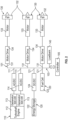
FIG. 1 is a schematic illustration of components of a distributed hybrid propulsion system of a vehicle in accordance with embodiments; -
FIG. 2 is a schematic illustration of installed components of a system configuration of a distributed hybrid propulsion system of a vehicle in accordance with embodiments; -
FIG. 3 is a schematic illustration of installed components of another system configuration of a distributed hybrid propulsion system of a vehicle in accordance with embodiments; -
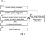
FIG. 4 is a flow diagram illustrating a method of configuring a vehicle in accordance with embodiments; and -
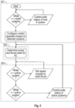
FIG. 5 is a flow diagram illustrating an operational method of a controller controlling a distributed hybrid propulsion system of a vehicle in accordance with embodiments. - In a serial hybrid power and propulsion system, power is distributed from a power source to a propulsor to generate thrust. In such a system, power can be generated and consumed at either end of the system. For example, power can be generated by motor-generators coupled to and powered by a gas turbine engine at a first end of the system and/or power can be generated by motor-generators coupled to propulsive rotors (e.g., rotors that produce thrust and/or lift) at a second end of the system.
- Conventional hybrid power and propulsion systems require substantial integration of disparate components, and oftentimes each of the components are provided by different sources (e.g., different manufacturers). This integration is required to ensure the disparate components are configured to communicate and/or otherwise function collaboratively to make the hybrid power and propulsion system work. Due to the substantial integration of disparate components, these conventional hybrid power and propulsion systems include fixed configurations that are typically rigid and unalterable. That is, once integration is complete, the traditional systems are configured to generate a fixed amount of energy and/or propulsive power.
- To address the shortcomings of the conventional systems, described herein is a modularized hybrid power and propulsion system that is versatile and scalable. That is, the present disclosure describes a plug-and-play or modularized, stacked approach for creating and controlling a hybrid power and propulsion system that may be used to power multiple platforms of disparate types and sizes. For example, a first platform (e.g., vehicle (e.g., aircraft, automobile, truck, vessel, etc.)) may include a first number of components (e.g., motors, fans, batteries, etc.) to provide sufficient energy to power the first platform and a second platform may include a second number of a same or similar type of components to provide sufficient energy to power the second platform. Thus, the first platform and the second platform may include a different number of same or similar components. For another example, a platform may include a first number of components to provide sufficient energy to power the platform for a first mission (e.g., traveling a first distance, carrying a first payload, etc.) and it may later be modified to include a second number of components to provide sufficient energy to power the platform for a second mission (e.g., traveling a second distance, carrying a second payload, etc.). In other words, various components may be added or removed based on the platform and/or an associated mission.
- As described below, the hybrid power and propulsion system includes a controller configured to dynamically control power demand (two-way) for power supply and/or power generation and to direct power to associated components installed on the platform via a common bus. Though described herein as being associated with a vehicle, with specific examples directed to aircraft, this is not intending to be so limiting, and the hybrid power and propulsion system described herein may be used in association with any platform, mobile or stationary.
- With reference to
FIG. 1 , a hybrid power andpropulsion system 101 is provided for use with a vehicle, such as an aircraft. The hybrid power andpropulsion system 101 includes respective pluralities of multiple classes of vehicle components 1021, 1022, 1023, acommon bus 103 that includes respective pluralities of multiple classes of plugs 1041, 1042, 1043 to which corresponding ones of the respective pluralities of multiple classes of vehicle components 1021, 1022, 1023 are connectable and acontroller 105. Thecontroller 105 is operably coupled to thecommon bus 103 and configured to ascertain a system configuration from connections to thecommon bus 103. - The
controller 105 can include a processing unit, a memory unit and an input-output (I/O) unit by which the processing unit is communicative with external elements. The memory unit is a non-transitory storage medium and has executable instructions stored thereon, which are readable and executable by the processing unit. When the executable instructions are read and executed by the processing unit, the processing unit and thecontroller 105 generally operate as described herein. - In greater detail, in accordance with embodiments, the hybrid power and
propulsion system 101 can include one or moreauxiliary engine assemblies 110, one or moreenergy storage elements 120 and one ormore drive assemblies 130. Thecommon bus 103 can includefirst plugs 111 to which each one of the one or moreauxiliary engine assemblies 110 is connectable,second plugs 121 to which each one of the one or moreenergy storage elements 120 is connectable andthird plugs 131 to which each one of the one ormore drive assemblies 130 is connectable. Thecontroller 105 is operably coupled to thecommon bus 103. Thecontroller 105 is configured to ascertain a system configuration from connections of the one or moreauxiliary engine assemblies 110 to thefirst plugs 111, from connections of the one or moreenergy storage elements 120 to thesecond plugs 121 and from connections of the one ormore drive assemblies 130 to the third plugs 131. - In some cases, the
controller 105 can be further configured to determine whether the system configuration accords with mission parameters prescribed for the vehicle. For example, thecontroller 105 can be configured to receive an input associated with a mission for the aircraft powered by the hybrid power andpropulsion system 101. Thecontroller 105 may evaluate one or more mission parameters (e.g., distance to be traveled, altitude, payload, etc.) associated with the mission to determine whether the components are optimized for mission completion. For example, thecontroller 105 may determine, based on the mission parameters for a first mission, that excess components are associated with the hybrid power andpropulsion system 101 onboard a vehicle. Thecontroller 105 may then provide an alert to recommend removal of one or more components of the hybrid power andpropulsion system 101 in order to optimize performance of the vehicle throughout the mission. For another example, thecontroller 105 may determine, based on mission parameters, that additional components need to be added to the vehicle to successfully complete the mission. Based on the determination, thecontroller 105 may then provide an alert instructing an operator or maintenance person to add additional components, to ensure successful mission completion. - At least one of the one or more
auxiliary engine assemblies 110 can include anengine 112, such as a turboshaft engine, one or more motor-generators 113 that are respectively coupled with theengine 112 to either drive an operation or theengine 112 or to generate electrical power from the operation of theengine 112 and, in some cases, inverters 114 (e.g., alternating current (AC)/direct current (DC) inverters) that are electrically interposable between each of the one or more motor-generators 113 and thecommon bus 103. In at least one embodiment, theengine 112 may be configured as a non-thrust/lift generating engine. In other words, theengine 112 may be configured to not generate motive power or thrust/lift for the vehicle (e.g., auxiliary power unit, etc.). - At least one of the one or more
energy storage elements 120 can include abattery 122 or afuel cell 123. In either case, an inverter 124 (e.g., a DC/DC inverter) can be electrically interposable between thebattery 122/fuel cell 123 and thecommon bus 103. - At least one of the one or
more drive assemblies 130 can include one or more fans orrotors 132, a motor-generator 133 coupled with the one or more fans orrotors 132 to drive operations of the one or more fans orrotors 132 and amotor drive 134 that controls operations of the motor-generator 133 and that is electrically interposable between the motor-generator 133 and thecommon bus 103. Although illustrated inFIG. 1 as a component separate from themotor 133, this is not intended to be so limiting, and themotor drive 134 may be incorporated into themotor 133, such as a component thereof. - In some embodiments, the motor-
generators 133 and fans orrotors 132 may be removably coupled to the hybrid power andpropulsion system 101 such that the motor-generators 133 and fans orrotors 132 may be added and/or removed based on mission needs and/or thrust/lift requirements of a vehicle. For example, the hybrid power andpropulsion system 101 may include two motor-generators 133 coupled to respective fans orrotors 132 in a first configuration and may include eight motor-generators 133 coupled to respective fans orrotors 132 in a second configuration. A greater or fewer number of motor-generators 133 and fans orrotors 132 is contemplated herein along with other types of component additions and removals, as described below. - As described above, the hybrid power and
propulsion system 101 can be scaled for various mission types. That is, thecommon bus 103 can have one or moreauxiliary engine assemblies 110, one or moreenergy storage elements 120 and one ormore drive assemblies 130 connected thereto and thecontroller 105 is configured to operate with any and all of the connection options. The scalability of the hybrid power andpropulsion system 101 reduces or eliminates a need for re-engineering or restructuring of a vehicle for each mission to which that vehicle is assigned and further reduces or eliminates a need for manual re-programming of thecontroller 105 each time thecontroller 105 encounters a new configuration. - In accordance with embodiments, each one of the one or more
auxiliary engine assemblies 110, each one of the one or moreenergy storage elements 120 and each one of the one ormore drive assemblies 130 is modular. As such, at least one of the one or moreauxiliary engine assemblies 110 can be of a unique type (i.e., with a unique structure, operational capabilities, structure, etc.) that is connectable nonetheless with thefirst plugs 111, at least one of the one or moreenergy storage elements 120 can be of a unique type (i.e., with a unique structure, operational capabilities, structure, etc.) that is connectable nonetheless with thesecond plugs 121 and at least one of the one ormore drive assemblies 130 can be of a unique type (i.e., with a unique structure, operational capabilities, structure, etc.) that is connectable nonetheless with the third plugs 131. The modularity of each one of the one or moreauxiliary engine assemblies 110, of each one of the one or moreenergy storage elements 120 and of each one of the one ormore drive assemblies 130 offers several advantages including, but not limited to, the ability for any one or more of theauxiliary engine assemblies 110, any one or more of theenergy storage elements 120 and any one or more of thedrive assemblies 130 to be sourced from varied and unique sources. - The hybrid power and
propulsion system 101 can further be configured to provide propulsion to a plurality of vehicles of different sizes. In the illustrative example ofFIG. 1 , the hybrid power andpropulsion system 101 can be configured to provide propulsion to different airframes of various sizes 1061, 1062 in which the system configuration is disposed. Each one of the plurality of airframes of one or more of the various sizes 1061, 1062 is configured to accommodate a hybrid power andpropulsion system 101 in one or more different configurations as described above, such as based on mission requirements. - With reference to
FIGS. 2 and3 , exemplary system configurations of the hybrid power andpropulsion system 101 ofFIG. 1 are provided. - As shown in
FIG. 2 , the hybrid power andpropulsion system 101 can include anauxiliary engine assembly 110 with asingle engine 112, two motor-generators 113 that are respectively coupled with thesingle engine 112 to either drive an operation of thesingle engine 112 or to generate electrical power from an operation of thesingle engine 112, and AC/DC inverters 114 that are electrically interposable between each of the one or more motor-generators 113 andfirst plugs 111 of thecommon bus 103. In addition, the hybrid power andpropulsion system 101 ofFIG. 2 can include twoenergy storage elements 120, one with abattery 122 and a DC/DC inverter 124 interposed between thebattery 122 and asecond plug 121 of thecommon bus 103 and one with afuel cell 123 that is directly connected asecond plug 121 of thecommon bus 103. Also, the hybrid power andpropulsion system 101 ofFIG. 2 can include threedrive assemblies 130, each including at least one fan orrotor 132, a motor-generator 133 coupled with the at least one fan orrotor 132 to drive operations of the fan orrotor 132 and amotor drive 134 that controls operations of the motor-generator 133 and that is electrically interposable between the motor-generator 133 and athird plug 131 of thecommon bus 103. In some embodiments, themotor drive 134 may control operation of the motor-generator 133 to cause the at least one fan orrotor 132 to operate and/or to operate at a particular speed. In embodiments in which two or more fans orrotors 132 are associated with a particular motor-generator 133, themotor drive 134 may be configured to control the motor-generator 133 to operate the two or more fans orrotors 132 at a same or similar or different speed. For example, themotor drive 134 may send a signal to the motor-generator 133 to cause the operation of a first fan orrotor 132 at a first speed and a second fan orrotor 132 at a second speed that is greater than the first speed. In at least one example, themotor drive 134 may generate the signal to the motor-generator 133 based on an input signal from thecontroller 105. In such an example, thecontroller 105 may be configured to drive the fan(s) or rotor(s) 132 of the hybrid power andpropulsion system 101 via themotor drive 134 and/or the motor-generator 133. - It can be assumed that the hybrid power and
propulsion system 101 ofFIG. 2 can be associated with an airframe of a certain size (e.g., size 1061), which is sufficient for supporting the above-described system configuration but which is not excessively large as compared to the above-described system configuration, and a set of loads 140 (e.g., on-board sensors, computing devices, environmental control systems (ECSs), etc.) that can each draw power from one of the power generation components during the mission. - In the hybrid power and
propulsion system 101 ofFIG. 2 , thecontroller 105 is operably coupled to thecommon bus 103 and configured to ascertain the above-described system configuration from each of the respective connections to thefirst plugs 111, thesecond plugs 121 and the third plugs 131. Thecontroller 105 is further configured to be receptive of mission parameters and to determine whether the system configuration accords with the mission parameters and the requirements of the set ofloads 140. If thecontroller 105 determines that the system configuration is appropriate for the mission parameters and the requirements of the set ofloads 140, thecontroller 105 can issue a positive signal to an operator and/or maintenance person. In this case, no system configuration changes would be necessary (e.g., no removal or addition of components). If thecontroller 105 determines that the system configuration is insufficient for the mission parameters and the requirements of the set of loads 140 (i.e., the system configuration lacks sufficient battery power), thecontroller 105 can issue an appropriate signal to the operator and/or maintenance person (e.g., that anadditional battery 122 is required) to add additional components (e.g., addmotor drive 134, motor-generator 133 and fan orrotor 132, add batteries, etc.). Additionally, if thecontroller 105 determines that the system configuration is excessive for the mission parameters and the requirements of the set ofloads 140, the controller can issue an appropriate signal to remove components. The signal can include an alert that the system configuration is satisfactory, insufficient, or excessive, and/or a recommendation of one or more modifications to make to the system configuration. - In addition to the operations described above, the
controller 105 is configured to control a flow of power to the set ofloads 140, to control bi-directional flows of power with respect to each of thefirst plugs 111, thesecond plugs 121 and thethird plugs 131 of thecommon bus 103 that are in use. The controller can be configured to take into consideration the bi-directional power flow capability in determining whether the system configuration accords with the mission parameters and the requirements of the set ofloads 140. As such, thecontroller 105 can consider the possibility of thebattery 122 being recharged by theauxiliary engine assembly 110 during the mission to thereby meet the requirements of the set ofloads 140 instead of recommending the insertion of anadditional battery 122. Thecontroller 105 may determine the recharging capabilities of thebatteries 122 based on the flight profile associated with the mission, such as a time to climb to altitude, a time at cruise, a time in descent, and the like. - As shown in
FIG. 3 , the hybrid power andpropulsion system 101 can include anenergy storage element 120, with abattery 122 and a DC/DC inverter 124 interposed between thebattery 122 and asecond plug 121 of thecommon bus 103, and two driveassemblies 130, each including at least one fan orrotor 132, a motor-generator 133 coupled with the at least one fan orrotor 132 to drive operations of the at least one fan orrotor 132 and amotor drive 134 that controls operations of the motor-generator 133 and that is electrically interposable between the motor-generator 133 and athird plug 131 of thecommon bus 103. - Again, it can be assumed that the hybrid power and
propulsion system 101 ofFIG. 3 can further include an air frame of a certain size 1061, which is sufficient for supporting the above-described system configuration, and a set ofloads 140 that draws power from one of the power generation components during the mission. - In the hybrid power and
propulsion system 101 ofFIG. 3 , thecontroller 105 is operably coupled to thecommon bus 103 and configured to ascertain the above-described system configuration from each of the respective connections to thesecond plug 121 and the third plugs 131. Thecontroller 105 is further configured to receive mission parameters, such as from an external source (e.g., mission computer input, etc.) and to determine whether the system configuration accords with the mission parameters and the requirements of the set ofloads 140. If thecontroller 105 determines that the system configuration is appropriate for the mission parameters and the requirements of the set ofloads 140, thecontroller 105 can issue a positive signal to an operator. - In addition to the operations described above, the
controller 105 is configured to control a flow of power to the set ofloads 140, to control bi-directional flows of power with respect to each of thesecond plugs 121 and thethird plugs 131 of thecommon bus 103 that are in use and to take into consideration the bi-directional power flow capability in determining whether the system configuration accords with the mission parameters and the requirements of the set ofloads 140. As such, thecontroller 105 can consider the possibility of thebattery 122 being recharged by one of the twoengines 130 during the mission to thereby meet the requirements of the set ofloads 140 instead of adding anadditional battery 122. - With reference to
FIG. 4 , amethod 400 of configuring a vehicle, such as an aircraft of various types and sizes, is provided. Atblock 401, themethod 400 includes receiving, at acontroller 105, mission parameters. In various embodiments, the mission parameters may be received from an external source, such as a mission signal input from a mission computing device. In some embodiments, the mission parameters may be input via a mission console of the aircraft, such as via a flight management computer or the like. - At
block 402, thecontroller 105 ascertains (e.g., determines) a system configuration from respective connections of one or more auxiliary engine assemblies (at least one of which is of a unique type), one or more energy storage elements (at least one of which is of a unique type) and one or more drive assemblies (at least one of which is of a unique type) to first, second and third plugs of a common bus. In other words, thecontroller 105 can determine a number components coupled to the first plug, second plug and/or third plug, and can determine the system configuration based on the couplings. - At
block 403, thecontroller 105 determines whether the system configuration satisfies the mission parameters. For example, thecontroller 105 determines whether the system configuration can produce enough electrical power to drive the fans orrotors 132 throughout the entirety of the mission based on the mission parameters, such as distance, altitude gained, payload to be carried, and the like. Based on a determination that the system configuration does not satisfy the mission parameters ("No" at block 403), thecontroller 105, atblock 404, generates and sends a signal to an operator/maintenance person to indicate that the system configuration does not satisfy mission parameters. In some embodiments, the signal can include a recommendation to add and/or remove particular components to satisfy the mission parameters. Based on a determination that the system configuration satisfies the mission parameters ("Yes" at block 403), thecontroller 105 can provide an indication thereof atblock 405. - At
block 406, thecontroller 105 can control a bi-directional power flow with respect each of the first, second and third plugs during mission operations. - With reference to
FIG. 5 , a further operational method of thecontroller 105 described above is provided. As shown inFIG. 5 , thecontroller 105 initially checks for active systems and system health at start-up or as needed (section 501). In the above-described scalable and modular hybrid power andpropulsion system 101, this is where thecontroller 105 determines which system configuration has been chosen for a given mission with polling done via network or bus communications. Next, based on vehicle or aircraft needs, thecontroller 105 determines effector settings to meet power distribution demands and thrust goals (section 502). Thecontroller 105 continues monitoring active systems and adjusts as needed (section 503). - Technical effects and benefits of the present disclosure are the provision of a hybrid power and propulsion system of a vehicle in which a serial hybrid configuration and a controller enables scalability and modularity that provides improved versatility in system designs. The controller allows for addition and removal of components without requiring complete restructuring or rebuilding of the system in question. The controller allows for the modularity that is not achieved in prior systems that require rework when components are added or removed.
- The corresponding structures, materials, acts and equivalents of all means or step plus function elements in the claims below are intended to include any structure, material, or act for performing the function in combination with other claimed elements as specifically claimed. The description of the present disclosure has been presented for purposes of illustration and description, but is not intended to be exhaustive or limited to the technical concepts in the form disclosed. Many modifications and variations will be apparent to those of ordinary skill in the art without departing from the scope and spirit of the disclosure. The embodiments were chosen and described in order to best explain the principles of the disclosure and the practical application and to enable others of ordinary skill in the art to understand the disclosure for various embodiments with various modifications as are suited to the particular use contemplated.
- While the preferred embodiments to the disclosure have been described, it will be understood that those skilled in the art, both now and in the future, may make various improvements and enhancements which fall within the scope of the claims which follow. These claims should be construed to maintain the proper protection for the disclosure first described.
Claims (15)
- A hybrid power and propulsion system (101) of a vehicle, comprising:an engine assembly (110) operably coupled to a common bus (103) via a first plug type (111), wherein the engine assembly (110) comprises a motor-generator (113) configured to generate electricity;a storage element (120) operably coupled to the common bus (103) via a second plug type (121), wherein the storage element (120) is configured to store the electricity;a drive assembly (130) operably coupled to the common bus (103) via a third plug type (131), wherein the drive assembly (130) is configured to receive the electricity from at least one of the engine assembly (110) or the storage element (120) to drive a propulsive fan (132); anda controller (105) operably connected to the common bus (103) and comprising a processor and a non-transitory computer-readable memory storing instructions that, when executed, cause the processor to control a flow of the electricity between at least one of the engine assembly (110), the storage element (120) and the drive assembly (130),wherein the common bus (103) is configured with at least two connectors of the second plug type (121) and the third plug type (131) to enable two or more storage elements (120) and two or more drive assemblies (130) to be removably connected to the hybrid power and propulsion system (101).
- The hybrid power and propulsion system (101) according to claim 1, wherein the instructions further cause the processor to:determine a system configuration based on connections to the common bus (103) via the first plug type (111), the second plug type (121) and the third plug (131) type;receive a mission input comprising one or more mission parameters; andbased on the one or more mission parameters, determine whether the system configuration is sufficient for the one or more mission parameters.
- The hybrid power and propulsion system (101) according to claim 2, wherein the instructions further cause the processor to:determine the system configuration is sufficient for the one or more mission parameters; andcause a message to be presented via a display of an operator or maintenance computing device indicating that the system configuration is sufficient.
- The hybrid power and propulsion system (101) according to claim 2 or 3, wherein the instructions further cause the processor to:determine the system configuration is not sufficient for the one or more mission parameters; andcause a message to be presented via a display of an operator or maintenance computing device indicating that the system configuration is insufficient, wherein the message comprises an indication to add at least one storage element (120) or at least one drive assembly (130) to the hybrid power and propulsion system (101).
- The hybrid power and propulsion system (101) according to claim 2, 3 or 4, wherein the instructions further cause the processor to:determine the system configuration includes excess components for the one or more mission parameters; andcause a message to be presented via a display of an operator or maintenance computing device indicating that the system configuration is excessive, wherein the message comprises an indication to remove at least one storage element (120) or at least one drive assembly (130) from the hybrid power and propulsion system (101).
- The hybrid power and propulsion system (101) according to claim 1, wherein the controller (105) is configured to:receive mission parameters associated with a mission for a vehicle associated with the hybrid power and propulsion system (101);determine that a system configuration includes excess components based on the mission parameters; andcause the storage element (120) or drive assembly (130) to be removed from the hybrid power and propulsion system (101).
- The hybrid power and propulsion system (101) according to claim 1, wherein the controller (105) is configured to:receive mission parameters associated with a mission for a vehicle associated with the hybrid power and propulsion system (101);determine that a system configuration is insufficient to complete the mission based on the mission parameters; andcause the storage element (120) or drive assembly (130) to be added to the hybrid power and propulsion system (101).
- The hybrid power and propulsion system (101) according to any preceding claim, further comprising a set of loads (140), wherein the instructions further cause the processor to control a flow of power to the set of loads (140) and bi-directional flows of power across the common bus (103).
- The hybrid power and propulsion system (101) according to any preceding claim, wherein the engine assembly (110) further comprises:an engine (112); anda motor-generator (113) coupled with the engine (112).
- The hybrid power and propulsion system (101) according to claim 9, wherein:the engine assembly (110) is an auxiliary engine assembly (110);the engine (112) is a gas turbine engine (112); andthe motor-generator (113) is configured to drive at least one spool of the gas turbine engine (112) in a first engine configuration and to generate electricity in a second engine configuration
- The hybrid power and propulsion system (101) according to any preceding claim, wherein the storage element (120) comprises at least one of a battery (122) or a fuel cell (123).
- The hybrid power and propulsion system (101) according to any preceding claim, wherein the drive assembly (130) comprises:a fan or rotor (132);a motor-generator (133) coupled with the fan or rotor (132); anda motor drive (134) electrically interposed between the motor-generator (133) of the drive assembly (130) and the common bus (103).
- The hybrid power and propulsion system (101) according to any preceding claim, wherein the drive assembly (130) comprises a pair of ducted rotors (132) coupled to a/the motor-generator (133) of the drive assembly (130), the motor-generator (13) of the drive assembly (130) configured to drive the pair of ducted rotors (132).
- A method of configuring a vehicle propulsion system (101), the method comprising:receiving mission parameters;ascertaining a system configuration from respective connections of an auxiliary engine assembly (110), one or more energy storage elements (120) and one or more drive assemblies (130) to first, second and third plugs (111, 121, 131) of a common bus (103); anddetermining whether the system configuration accords with the mission parameters.
- The method according to claim 14, further comprising:based on a determination that the system configuration accords with the mission parameters, causing a first message to be presented via a display of a computing device, the first message including an indication that the system configuration accords with the mission parameters; orbased on a determination that the system configuration does not accord with mission parameters, causing a second message to be presented via the display, the second message including an instruction to either add or remove a component to/from the vehicle propulsion system (101).
Applications Claiming Priority (1)
| Application Number | Priority Date | Filing Date | Title |
|---|---|---|---|
| US18/330,608 US20240410315A1 (en) | 2023-06-07 | 2023-06-07 | Stacked approach for distributed hybrid propulsion with scalability and modularity |
Publications (1)
| Publication Number | Publication Date |
|---|---|
| EP4474284A1 true EP4474284A1 (en) | 2024-12-11 |
Family
ID=91465209
Family Applications (1)
| Application Number | Title | Priority Date | Filing Date |
|---|---|---|---|
| EP24180916.9A Pending EP4474284A1 (en) | 2023-06-07 | 2024-06-07 | Stacked approach for distributed hybrid propulsion with scalability and modularity |
Country Status (2)
| Country | Link |
|---|---|
| US (1) | US20240410315A1 (en) |
| EP (1) | EP4474284A1 (en) |
Citations (2)
| Publication number | Priority date | Publication date | Assignee | Title |
|---|---|---|---|---|
| WO2016093905A1 (en) * | 2014-08-29 | 2016-06-16 | Tzunum Aircraft Llc | System and methods for implementing regional air transit network using hybrid-electric aircraft |
| EP3650353B1 (en) * | 2018-11-08 | 2022-06-29 | Rolls-Royce North American Technologies, Inc. | Hybrid propulsion systems |
Family Cites Families (3)
| Publication number | Priority date | Publication date | Assignee | Title |
|---|---|---|---|---|
| US11401041B2 (en) * | 2018-07-30 | 2022-08-02 | Raytheon Technologies Corporation | Hybrid electric power distribution and control for an aircraft |
| US11501483B2 (en) * | 2018-12-10 | 2022-11-15 | ImageKeeper, LLC | Removable sensor payload system for unmanned aerial vehicle performing media capture and property analysis |
| IT202200016215A1 (en) * | 2022-07-29 | 2024-01-29 | Gen Electric | CONTROL OF FULLY ELECTRIC OR HYBRID-ELECTRIC PROPULSION AND TRANSMISSION SYSTEMS |
-
2023
- 2023-06-07 US US18/330,608 patent/US20240410315A1/en active Pending
-
2024
- 2024-06-07 EP EP24180916.9A patent/EP4474284A1/en active Pending
Patent Citations (2)
| Publication number | Priority date | Publication date | Assignee | Title |
|---|---|---|---|---|
| WO2016093905A1 (en) * | 2014-08-29 | 2016-06-16 | Tzunum Aircraft Llc | System and methods for implementing regional air transit network using hybrid-electric aircraft |
| EP3650353B1 (en) * | 2018-11-08 | 2022-06-29 | Rolls-Royce North American Technologies, Inc. | Hybrid propulsion systems |
Also Published As
| Publication number | Publication date |
|---|---|
| US20240410315A1 (en) | 2024-12-12 |
Similar Documents
| Publication | Publication Date | Title |
|---|---|---|
| US11273920B2 (en) | Method and a device for managing the energy of a hybrid power plant of a multi-rotor aircraft | |
| CN104884349B (en) | The management method of the electric power networks of aircraft | |
| CN110116812A (en) | For the drive system of aircraft and for providing the method for driving power for aircraft | |
| CN114537681A (en) | System and method for distributing propulsion load power drawn from high-power and high-power batteries | |
| KR102683767B1 (en) | Aircraft with hybrid power source | |
| JP6907175B2 (en) | Power system | |
| US20210039801A1 (en) | Hybrid electric aircraft energy regeneration | |
| US11001388B1 (en) | Systems and methods for power distribution in a drone aircraft | |
| US20210229821A1 (en) | Aircraft with electrical energy storage in nacelles | |
| US12071250B2 (en) | Electric architecture for hybrid propulsion | |
| CN116890999A (en) | aircraft controls | |
| US11784506B2 (en) | Power transformation with power source balancing in an apparatus | |
| KR102899388B1 (en) | Aircraft with hybrid power source | |
| EP4474284A1 (en) | Stacked approach for distributed hybrid propulsion with scalability and modularity | |
| KR102871024B1 (en) | Hybrid propulsion chain for aircraft including auxiliary mechanical drive system | |
| US11745881B2 (en) | Fuel cell stack array | |
| CN114435601B (en) | Distributed Power-Split Architecture for UAV Applications | |
| US12280678B2 (en) | Power and energy management for distributed hybrid propulsion | |
| CN115848167A (en) | Control method and device of engineering vehicle, readable storage medium and engineering vehicle | |
| JP2023124915A (en) | Aircraft power supply circuit | |
| US20230339619A1 (en) | Electric power system of moving object | |
| US12494644B2 (en) | Power supply controller | |
| US20250296681A1 (en) | Control system, moving object, and information processing method of control system | |
| US12301002B2 (en) | Power dispatch control system for multiple power generation sources | |
| KR102790513B1 (en) | Hybrid eVTOL Aircraft System with Minimum Battery Operation and Operating Method thereof |
Legal Events
| Date | Code | Title | Description |
|---|---|---|---|
| PUAI | Public reference made under article 153(3) epc to a published international application that has entered the european phase |
Free format text: ORIGINAL CODE: 0009012 |
|
| STAA | Information on the status of an ep patent application or granted ep patent |
Free format text: STATUS: THE APPLICATION HAS BEEN PUBLISHED |
|
| AK | Designated contracting states |
Kind code of ref document: A1 Designated state(s): AL AT BE BG CH CY CZ DE DK EE ES FI FR GB GR HR HU IE IS IT LI LT LU LV MC ME MK MT NL NO PL PT RO RS SE SI SK SM TR |
|
| STAA | Information on the status of an ep patent application or granted ep patent |
Free format text: STATUS: REQUEST FOR EXAMINATION WAS MADE |
|
| 17P | Request for examination filed |
Effective date: 20250611 |
|
| STAA | Information on the status of an ep patent application or granted ep patent |
Free format text: STATUS: EXAMINATION IS IN PROGRESS |
|
| 17Q | First examination report despatched |
Effective date: 20260130 |