EP4474280A1 - Electric aircraft engine and compressor for engine retrofit - Google Patents
Electric aircraft engine and compressor for engine retrofit Download PDFInfo
- Publication number
- EP4474280A1 EP4474280A1 EP24181229.6A EP24181229A EP4474280A1 EP 4474280 A1 EP4474280 A1 EP 4474280A1 EP 24181229 A EP24181229 A EP 24181229A EP 4474280 A1 EP4474280 A1 EP 4474280A1
- Authority
- EP
- European Patent Office
- Prior art keywords
- electric
- aircraft
- engine
- compressed air
- compressor
- Prior art date
- Legal status (The legal status is an assumption and is not a legal conclusion. Google has not performed a legal analysis and makes no representation as to the accuracy of the status listed.)
- Granted
Links
Images


Classifications
-
- B—PERFORMING OPERATIONS; TRANSPORTING
- B64—AIRCRAFT; AVIATION; COSMONAUTICS
- B64D—EQUIPMENT FOR FITTING IN OR TO AIRCRAFT; FLIGHT SUITS; PARACHUTES; ARRANGEMENT OR MOUNTING OF POWER PLANTS OR PROPULSION TRANSMISSIONS IN AIRCRAFT
- B64D27/00—Arrangement or mounting of power plants in aircraft; Aircraft characterised by the type or position of power plants
- B64D27/02—Aircraft characterised by the type or position of power plants
- B64D27/30—Aircraft characterised by electric power plants
- B64D27/34—All-electric aircraft
-
- B—PERFORMING OPERATIONS; TRANSPORTING
- B64—AIRCRAFT; AVIATION; COSMONAUTICS
- B64D—EQUIPMENT FOR FITTING IN OR TO AIRCRAFT; FLIGHT SUITS; PARACHUTES; ARRANGEMENT OR MOUNTING OF POWER PLANTS OR PROPULSION TRANSMISSIONS IN AIRCRAFT
- B64D13/00—Arrangements or adaptations of air-treatment apparatus for aircraft crew or passengers, or freight space
- B64D13/06—Arrangements or adaptations of air-treatment apparatus for aircraft crew or passengers, or freight space the air being conditioned
-
- B—PERFORMING OPERATIONS; TRANSPORTING
- B64—AIRCRAFT; AVIATION; COSMONAUTICS
- B64D—EQUIPMENT FOR FITTING IN OR TO AIRCRAFT; FLIGHT SUITS; PARACHUTES; ARRANGEMENT OR MOUNTING OF POWER PLANTS OR PROPULSION TRANSMISSIONS IN AIRCRAFT
- B64D15/00—De-icing or preventing icing on exterior surfaces of aircraft
-
- B—PERFORMING OPERATIONS; TRANSPORTING
- B64—AIRCRAFT; AVIATION; COSMONAUTICS
- B64D—EQUIPMENT FOR FITTING IN OR TO AIRCRAFT; FLIGHT SUITS; PARACHUTES; ARRANGEMENT OR MOUNTING OF POWER PLANTS OR PROPULSION TRANSMISSIONS IN AIRCRAFT
- B64D15/00—De-icing or preventing icing on exterior surfaces of aircraft
- B64D15/02—De-icing or preventing icing on exterior surfaces of aircraft by ducted hot gas or liquid
- B64D15/04—Hot gas application
-
- B—PERFORMING OPERATIONS; TRANSPORTING
- B64—AIRCRAFT; AVIATION; COSMONAUTICS
- B64D—EQUIPMENT FOR FITTING IN OR TO AIRCRAFT; FLIGHT SUITS; PARACHUTES; ARRANGEMENT OR MOUNTING OF POWER PLANTS OR PROPULSION TRANSMISSIONS IN AIRCRAFT
- B64D27/00—Arrangement or mounting of power plants in aircraft; Aircraft characterised by the type or position of power plants
- B64D27/02—Aircraft characterised by the type or position of power plants
- B64D27/30—Aircraft characterised by electric power plants
- B64D27/31—Aircraft characterised by electric power plants within, or attached to, wings
-
- B—PERFORMING OPERATIONS; TRANSPORTING
- B64—AIRCRAFT; AVIATION; COSMONAUTICS
- B64D—EQUIPMENT FOR FITTING IN OR TO AIRCRAFT; FLIGHT SUITS; PARACHUTES; ARRANGEMENT OR MOUNTING OF POWER PLANTS OR PROPULSION TRANSMISSIONS IN AIRCRAFT
- B64D27/00—Arrangement or mounting of power plants in aircraft; Aircraft characterised by the type or position of power plants
- B64D27/02—Aircraft characterised by the type or position of power plants
- B64D27/30—Aircraft characterised by electric power plants
- B64D27/32—Aircraft characterised by electric power plants within, or attached to, fuselages
-
- B—PERFORMING OPERATIONS; TRANSPORTING
- B64—AIRCRAFT; AVIATION; COSMONAUTICS
- B64D—EQUIPMENT FOR FITTING IN OR TO AIRCRAFT; FLIGHT SUITS; PARACHUTES; ARRANGEMENT OR MOUNTING OF POWER PLANTS OR PROPULSION TRANSMISSIONS IN AIRCRAFT
- B64D29/00—Power-plant nacelles, fairings or cowlings
-
- B—PERFORMING OPERATIONS; TRANSPORTING
- B64—AIRCRAFT; AVIATION; COSMONAUTICS
- B64D—EQUIPMENT FOR FITTING IN OR TO AIRCRAFT; FLIGHT SUITS; PARACHUTES; ARRANGEMENT OR MOUNTING OF POWER PLANTS OR PROPULSION TRANSMISSIONS IN AIRCRAFT
- B64D35/00—Transmitting power from power plants to propellers or rotors; Arrangements of transmissions
- B64D35/02—Transmitting power from power plants to propellers or rotors; Arrangements of transmissions specially adapted for specific power plants
- B64D35/021—Transmitting power from power plants to propellers or rotors; Arrangements of transmissions specially adapted for specific power plants for electric power plants
- B64D35/026—Transmitting power from power plants to propellers or rotors; Arrangements of transmissions specially adapted for specific power plants for electric power plants the electric power plant being integral with the propeller or rotor
-
- B—PERFORMING OPERATIONS; TRANSPORTING
- B64—AIRCRAFT; AVIATION; COSMONAUTICS
- B64D—EQUIPMENT FOR FITTING IN OR TO AIRCRAFT; FLIGHT SUITS; PARACHUTES; ARRANGEMENT OR MOUNTING OF POWER PLANTS OR PROPULSION TRANSMISSIONS IN AIRCRAFT
- B64D13/00—Arrangements or adaptations of air-treatment apparatus for aircraft crew or passengers, or freight space
- B64D13/06—Arrangements or adaptations of air-treatment apparatus for aircraft crew or passengers, or freight space the air being conditioned
- B64D2013/0603—Environmental Control Systems
Definitions
- This application relates to an electric aircraft engine that includes an electric compressor within its nacelle such that it can be retrofit to existing gas turbine engine powered aircraft.
- Aircraft typically have one or more gas turbine engines.
- the gas turbine engines provide propulsion through a propulsor such as a propeller or fan.
- the propulsor delivers air into a compressor section where the air is compressed and then delivered into a combustor.
- the compressed air is mixed with fuel and ignited. Products of this combustion pass downstream over turbine rotors, driving them to rotate.
- aircraft include a number of complex systems. Several require compressed air. As one example there are anti-ice systems which receive hot compressed air to deliver air outwardly to melt or shed ice. Such a system may be mounted in the wing of the aircraft. Another system is an environmental control system which provides conditioned air into an aircraft cabin, the cockpit, storage areas, and for other functions.
- the gas turbine engine compressor typically has one or two taps which tap compressed air to be delivered to the anti-ice system and the ECS system.
- the compressed air taps are connected into the aircraft fuselage and wing through connections extending through a strut or mount that attaches the engine to the aircraft.
- Future aircraft systems may be designed to incorporate such electric engines and use a source of compressed air other than a gas turbine engine compressor.
- retrofitting current aircraft with an electric engine would raise challenges as there would be no way to supply the compressed air to systems such as the anti-ice system and ECS without reworking the system.
- an electric aircraft engine includes an electric motor driving a propulsor.
- a power source powers the electric motor.
- An electric compressor supplies compressed air.
- a nacelle surrounds the electric motor, the power source and the electric compressor.
- a method of retrofitting an existing aircraft includes the steps of providing an aircraft having a gas turbine engine with a gas turbine engine compressor. There is at least one compressed air tap for supplying compressed air from the gas turbine engine compressor to an anti-ice system and to an environmental control system through compressed air connections.
- the method includes removing the gas turbine engine including disconnecting the gas turbine engine compressor from the compressed air connections to the anti-ice system and the environmental control system.
- the method then mounts an electric engine to the aircraft.
- the electric engine includes an electric motor driving a propulsor.
- a power source powers the electric motor.
- An electric compressor supplies compressed air, and a nacelle surrounds the electric motor, the power source and the electric compressor.
- the mounting step includes connecting the electric compressor to the compressed air connections to supply compressed air to the anti-ice system and to the environmental control system.
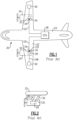
- a current aircraft 20 is illustrated highly schematically in Figure 1 .
- Wings 22 are shown as is a fuselage 23.
- Engines 24 are shown mounted beneath the wings 22. It should be understood that in some applications the engines could be mounted to the fuselage 23, and such aircraft would also benefit from this disclosure.
- the prior art engines 24 are gas turbine engines having a compressor 26 as described above.
- the compressor 26 is shown delivering air through tap 28 to an anti-ice system 30.
- Compressor 26 also has a low pressure tap 32 and a high pressure tap 34 communicating to a valve 134 that sends air, via a valve output 135, to a connection 132 leading to an ECS system 36.
- Systems 30 and 36 are shown schematically. In practice both are very complex systems. It may be desirable to retrofit an electric engine to replace engines 24, as explained below. Due to the complexity of systems 30 and 36 it would be desirable to not replace or even modify systems 30 and 36 when retrofitting the engine. This disclosure facilitates this goal.
- the engines 24 are mounted to the wing 22 through a strut or pylon 40.
- the connections 128 and 132 extend through the pylon 40.
- FIG. 3 shows an engine, and anti-ice and ECS systems under this disclosure.
- An electric engine 100 supplies air through a tap 28 to a connection 128 on aircraft 20 and then to an anti-ice system 30.
- the electric engine 100 also supplies air through a tap 32 to a connection 132 on aircraft 20 and then to an ECS system 36.
- the engine 100 includes an electric motor 109 driving propeller 108.
- Some power storage device 110 is utilized to power the electric motor 109.
- the power storage devices 110 may be batteries, fuel cells, ultracapacitors, or any other acceptable power storage device.
- An electric compressor 112 is shown supplying compressed air to the taps 28 and 32. Taps 28 and 32 are connected to connections 128 and 132, respectively.
- the electric compressor 112 may also be powered by the power storage device 110. However, other power sources may drive the electric motor for compressor 112. Air is supplied to the electric compressor 112 through openings 114 in a nacelle 106. Alternatively, or in combination, an air scoop 116 is formed in nacelle 106. The air is compressed and delivered to the anti-ice system 30 and the ECS 36.
- the electric compressor 112, electric motor 109 and power storage devices 110 are mounted within the nacelle 106. This has benefits when retrofitting an aircraft with an existing gas turbine to have engine 100.
- Future aircraft that are to utilize electric engines will have their anti-ice system and environmental control system designed to receive compressed air from a source other than a gas turbine engine compressor. However, it may be desirable to retrofit existing aircraft with such an electric engine 100. Although the anti-ice system 30 and the environmental control system 36 are shown as black boxes in fact they are very complex systems. It would be burdensome to redesign or replace these systems to receive an alternative source of compressed air. By utilizing this disclosure, one can work with both systems as existing on the aircraft being retrofit.
- Figure 4A shows a first step in retrofitting the aircraft 20.
- the existing gas turbine engines 24 are removed, leaving the strut 40 and connections 128 and 132.
- an electric engine 100 is attached to the strut 40.
- Taps 28 and 32 such as shown in Figure 3 are connected into the anti-ice system and ECS system through connections 128 and 132, respectively.
- the compressed air connections from the electric compressor 112 are now connected into the existing conduits 128 and 132 in the strut 40.
- the anti-ice system 30 and the ECS system 36 need not be modified in combination with retrofitting the aircraft with the electric engine.
- FIG. 5 shows an alternative embodiment 200.
- a bus bar 202 communicates electric power from a power storage device 201 which may be mounted on the aircraft, such as in wing 22.
- An electric aircraft engine 100 under this disclosure could be said to include an electric motor 109 driving a propulsor 108.
- a power source 110 powers the electric motor 109.
- An electric compressor 112 supplies compressed air.
- a nacelle 106 surrounds the electric motor, the power source and the electric compressor.
- the power source is a power storage device.
- the power storage device also powers the electric compressor.
- an air inlet communicates through the nacelle to the electric compressor.
- the air inlet is provided by a scoop inlet in an outer peripheral surface of the nacelle.
- the air inlet is formed in a forward face of the nacelle adjacent the propulsor.
- the power storage device is at least one of a battery, a fuel cell and an ultracapacitor.
- An aircraft 20 under this disclosure could be said to include a fuselage 23 and a pair of wings 22.
- An anti-ice system 30 is provided in at least one of the pair of wings and fuselage.
- the anti-ice system is operable to receive compressed air and deliver it to areas of the at least one of the pair of wings or fuselage to melt ice. Alternatively, the anti-ice system may deliver air to pressurize deicer boots which will shed ice from the wings.
- An environmental control system 36 receives compressed air and utilizes the compressed air within a cabin of the aircraft fuselage 23.
- An electric engine 100 is connected to at least one of the pair of wings and the fuselage through a pylon 40.
- the electric engine 100 includes an electric motor 109 driving a propulsor 108.
- a power storage device and a power source 110 powers the electric motor.
- An electric compressor 112 supplies compressed air.
- a nacelle 106 surrounds the electric motor, the power source and the electric compressor. Compressed air from the electric compressor is connected to pass outwardly of the nacelle 106 and to the anti-ice system 30 and to the environmental control system 36.
- the power source is the power storage device that is also within the nacelle.
- the power source is a bus bar receiving power from the power storage device and the power storage device is mounted in at least one of the fuselage and wing.
- the power storage device also powers the electric compressor.
- the power storage device is at least one of a battery, a fuel cell and an ultracapacitor.
- an air inlet communicates through the nacelle to the electric compressor.
- the air inlet is provided by a scoop inlet in an outer peripheral surface of a nacelle.
- the air inlet is formed in a forward face of a nacelle adjacent the propulsor.
- a method of retrofitting an existing aircraft under this disclosure could be said to include the steps of providing an aircraft 20 having a gas turbine engine 24 with a gas turbine engine compressor 26. There is at least one compressed air tap 28/32/34 for supplying compressed air from the gas turbine engine compressor to an anti-ice system 30 and to an environmental control system 36 through compressed air connections 128/132.
- the method includes removing the gas turbine engine, including disconnecting the gas turbine engine compressor from the compressed air connections anti-ice system and the environmental control system.
- the method then mounts an electric engine 100 to the aircraft.
- the electric engine includes an electric motor 109 driving a propulsor 108.
- the electric engine further includes a power storage device 110 powers the electric motor.
- the electric engine further includes an electric compressor 112 for supplying compressed air, and a nacelle surrounding the electric motor, the power storage device and the electric compressor.
- the mounting step includes connecting the electric compressor to the compressed air connections to supply compressed air to the anti-ice system and to the environmental control system.
- the gas turbine engine prior to the removing step is attached to the aircraft through a pylon, and the electric engine is mounted to the pylon.
- the power source is a power storage device that is also within the nacelle.
- the power source is a bus bar receiving power from a power storage device mounted in at least one of the fuselage and wing.
- the power storage device also powers the electric compressor.
Landscapes
- Engineering & Computer Science (AREA)
- Aviation & Aerospace Engineering (AREA)
- Mechanical Engineering (AREA)
- Health & Medical Sciences (AREA)
- General Health & Medical Sciences (AREA)
- Pulmonology (AREA)
- Structures Of Non-Positive Displacement Pumps (AREA)
- Manufacturing & Machinery (AREA)
- Transportation (AREA)
Abstract
Description
- This application relates to an electric aircraft engine that includes an electric compressor within its nacelle such that it can be retrofit to existing gas turbine engine powered aircraft.
- Aircraft typically have one or more gas turbine engines. The gas turbine engines provide propulsion through a propulsor such as a propeller or fan. Typically, the propulsor delivers air into a compressor section where the air is compressed and then delivered into a combustor. In the combustor the compressed air is mixed with fuel and ignited. Products of this combustion pass downstream over turbine rotors, driving them to rotate.
- As can be appreciated, aircraft include a number of complex systems. Several require compressed air. As one example there are anti-ice systems which receive hot compressed air to deliver air outwardly to melt or shed ice. Such a system may be mounted in the wing of the aircraft. Another system is an environmental control system which provides conditioned air into an aircraft cabin, the cockpit, storage areas, and for other functions.
- In current aircraft, the gas turbine engine compressor typically has one or two taps which tap compressed air to be delivered to the anti-ice system and the ECS system.
- The compressed air taps are connected into the aircraft fuselage and wing through connections extending through a strut or mount that attaches the engine to the aircraft.
- There are efforts underway to replace gas turbine engines with electric powered engines or a hybrid of the two. This will reduce fuel burn, emissions and potentially noise.
- Future aircraft systems may be designed to incorporate such electric engines and use a source of compressed air other than a gas turbine engine compressor. However, retrofitting current aircraft with an electric engine would raise challenges as there would be no way to supply the compressed air to systems such as the anti-ice system and ECS without reworking the system.
- According to an aspect of the present invention, an electric aircraft engine includes an electric motor driving a propulsor. A power source powers the electric motor. An electric compressor supplies compressed air. A nacelle surrounds the electric motor, the power source and the electric compressor. An aircraft having such an engine is also disclosed.
- According to another aspect of the present invention, a method of retrofitting an existing aircraft includes the steps of providing an aircraft having a gas turbine engine with a gas turbine engine compressor. There is at least one compressed air tap for supplying compressed air from the gas turbine engine compressor to an anti-ice system and to an environmental control system through compressed air connections. The method includes removing the gas turbine engine including disconnecting the gas turbine engine compressor from the compressed air connections to the anti-ice system and the environmental control system. The method then mounts an electric engine to the aircraft. The electric engine includes an electric motor driving a propulsor. A power source powers the electric motor. An electric compressor supplies compressed air, and a nacelle surrounds the electric motor, the power source and the electric compressor. The mounting step includes connecting the electric compressor to the compressed air connections to supply compressed air to the anti-ice system and to the environmental control system.
- Features of embodiments are recited in the dependent claims.
- These and other features will be best understood from the following drawings and specification, the following is a brief description.
-
-
Figure 1 shows a prior art aircraft. -
Figure 2 shows a detail of the prior art aircraft. -
Figure 3 shows an aircraft engine according to this disclosure connecting into an aircraft. -
Figure 4A shows a first step in retrofitting theFigure 2 aircraft with theFigure 3 engine. -
Figure 4B shows a subsequent step in retrofitting theFigure 3 engine onto the prior art aircraft. -
Figure 5 shows another engine embodiment. - A
current aircraft 20 is illustrated highly schematically inFigure 1 .Wings 22 are shown as is afuselage 23.Engines 24 are shown mounted beneath thewings 22. It should be understood that in some applications the engines could be mounted to thefuselage 23, and such aircraft would also benefit from this disclosure. Theprior art engines 24 are gas turbine engines having acompressor 26 as described above. Thecompressor 26 is shown delivering air throughtap 28 to ananti-ice system 30.Compressor 26 also has alow pressure tap 32 and ahigh pressure tap 34 communicating to avalve 134 that sends air, via avalve output 135, to aconnection 132 leading to anECS system 36. - While two
engines 24 are illustrated onaircraft 20, this disclosure extends to aircraft having a single engine or more than two engines. -
Systems engines 24, as explained below. Due to the complexity ofsystems systems - As shown in the prior art
Figure 2 , theengines 24 are mounted to thewing 22 through a strut orpylon 40. Theconnections pylon 40. -
Figure 3 shows an engine, and anti-ice and ECS systems under this disclosure. Anelectric engine 100 supplies air through atap 28 to aconnection 128 onaircraft 20 and then to ananti-ice system 30. Theelectric engine 100 also supplies air through atap 32 to aconnection 132 onaircraft 20 and then to anECS system 36. - The
engine 100 includes anelectric motor 109driving propeller 108. Somepower storage device 110 is utilized to power theelectric motor 109. Thepower storage devices 110 may be batteries, fuel cells, ultracapacitors, or any other acceptable power storage device. - An
electric compressor 112 is shown supplying compressed air to thetaps Taps connections electric compressor 112 may also be powered by thepower storage device 110. However, other power sources may drive the electric motor forcompressor 112. Air is supplied to theelectric compressor 112 throughopenings 114 in anacelle 106. Alternatively, or in combination, anair scoop 116 is formed innacelle 106. The air is compressed and delivered to theanti-ice system 30 and theECS 36. - Notably, the
electric compressor 112,electric motor 109 andpower storage devices 110 are mounted within thenacelle 106. This has benefits when retrofitting an aircraft with an existing gas turbine to haveengine 100. - Future aircraft that are to utilize electric engines will have their anti-ice system and environmental control system designed to receive compressed air from a source other than a gas turbine engine compressor. However, it may be desirable to retrofit existing aircraft with such an
electric engine 100. Although theanti-ice system 30 and theenvironmental control system 36 are shown as black boxes in fact they are very complex systems. It would be burdensome to redesign or replace these systems to receive an alternative source of compressed air. By utilizing this disclosure, one can work with both systems as existing on the aircraft being retrofit. - This will reduce the burden of having to make any such changes to those systems.
-
Figure 4A shows a first step in retrofitting theaircraft 20. The existinggas turbine engines 24 are removed, leaving thestrut 40 andconnections - Next, as shown in
Figure 4B , anelectric engine 100 is attached to thestrut 40.Taps Figure 3 are connected into the anti-ice system and ECS system throughconnections electric compressor 112 are now connected into the existingconduits strut 40. One does not need two taps to theECS system 36 as thecompressor 112 can be ran at a constant speed no matter the power state ofmotor 109. Thus, theanti-ice system 30 and theECS system 36 need not be modified in combination with retrofitting the aircraft with the electric engine. -
Figure 5 shows analternative embodiment 200. Here there is not a power storage device within the nacelle 206. Rather, abus bar 202 communicates electric power from apower storage device 201 which may be mounted on the aircraft, such as inwing 22. - An
electric aircraft engine 100 under this disclosure could be said to include anelectric motor 109 driving apropulsor 108. Apower source 110 powers theelectric motor 109. Anelectric compressor 112 supplies compressed air. Anacelle 106 surrounds the electric motor, the power source and the electric compressor. - In another embodiment according to the previous embodiment, the power source is a power storage device.
- In another embodiment according to any of the previous embodiments, the power storage device also powers the electric compressor.
- In another embodiment according to any of the previous embodiments, an air inlet communicates through the nacelle to the electric compressor.
- In another embodiment according to any of the previous embodiments, the air inlet is provided by a scoop inlet in an outer peripheral surface of the nacelle.
- In another embodiment according to any of the previous embodiments, the air inlet is formed in a forward face of the nacelle adjacent the propulsor.
- In another embodiment according to any of the previous embodiments, the power storage device is at least one of a battery, a fuel cell and an ultracapacitor.
- An
aircraft 20 under this disclosure could be said to include afuselage 23 and a pair ofwings 22. Ananti-ice system 30 is provided in at least one of the pair of wings and fuselage. The anti-ice system is operable to receive compressed air and deliver it to areas of the at least one of the pair of wings or fuselage to melt ice. Alternatively, the anti-ice system may deliver air to pressurize deicer boots which will shed ice from the wings. Anenvironmental control system 36 receives compressed air and utilizes the compressed air within a cabin of theaircraft fuselage 23. Anelectric engine 100 is connected to at least one of the pair of wings and the fuselage through apylon 40. Theelectric engine 100 includes anelectric motor 109 driving apropulsor 108. A power storage device and apower source 110 powers the electric motor. Anelectric compressor 112 supplies compressed air. Anacelle 106 surrounds the electric motor, the power source and the electric compressor. Compressed air from the electric compressor is connected to pass outwardly of thenacelle 106 and to theanti-ice system 30 and to theenvironmental control system 36. - In another embodiment according to any of the previous embodiments, the power source is the power storage device that is also within the nacelle.
- In another embodiment according to any of the previous embodiments, the power source is a bus bar receiving power from the power storage device and the power storage device is mounted in at least one of the fuselage and wing.
- In another embodiment according to any of the previous embodiments, the power storage device also powers the electric compressor.
- In another embodiment according to any of the previous embodiments, the power storage device is at least one of a battery, a fuel cell and an ultracapacitor.
- In another embodiment according to any of the previous embodiments, an air inlet communicates through the nacelle to the electric compressor.
- In another embodiment according to any of the previous embodiments, the air inlet is provided by a scoop inlet in an outer peripheral surface of a nacelle.
- In another embodiment according to any of the previous embodiments, the air inlet is formed in a forward face of a nacelle adjacent the propulsor.
- A method of retrofitting an existing aircraft under this disclosure could be said to include the steps of providing an
aircraft 20 having agas turbine engine 24 with a gasturbine engine compressor 26. There is at least onecompressed air tap 28/32/34 for supplying compressed air from the gas turbine engine compressor to ananti-ice system 30 and to anenvironmental control system 36 throughcompressed air connections 128/132. The method includes removing the gas turbine engine, including disconnecting the gas turbine engine compressor from the compressed air connections anti-ice system and the environmental control system. The method then mounts anelectric engine 100 to the aircraft. The electric engine includes anelectric motor 109 driving apropulsor 108. The electric engine further includes apower storage device 110 powers the electric motor. The electric engine further includes anelectric compressor 112 for supplying compressed air, and a nacelle surrounding the electric motor, the power storage device and the electric compressor. The mounting step includes connecting the electric compressor to the compressed air connections to supply compressed air to the anti-ice system and to the environmental control system. - In another embodiment according to any of the previous embodiments, prior to the removing step the gas turbine engine is attached to the aircraft through a pylon, and the electric engine is mounted to the pylon.
- In another embodiment according to any of the previous embodiments, the power source is a power storage device that is also within the nacelle.
- In another embodiment according to any of the previous embodiments, the power source is a bus bar receiving power from a power storage device mounted in at least one of the fuselage and wing.
- In another embodiment according to any of the previous embodiments, the power storage device also powers the electric compressor.
- Although embodiments have been disclosed, a worker of skill in this art would recognize that modifications would come within the scope of this disclosure. For that reason, the following claims should be studied to determine the true scope and content.
Claims (15)
- An electric aircraft engine (100; 200) comprising:an electric motor (109) driving a propulsor (108);a power source (110) for powering the electric motor (109);an electric compressor (112) for supplying compressed air; anda nacelle (106; 206) surrounding said electric motor (109), said power source (110; 202) and said electric compressor (112).
- The electric aircraft engine (100) of claim 1, wherein the power source (110) is a power storage device (110).
- The electric aircraft engine (100) of claim 2, wherein the power storage device (110) also powers the electric compressor (112).
- The electric aircraft engine (100) of claim 2 or 3, wherein the power storage device (110) is at least one of a battery, a fuel cell and an ultracapacitor.
- The electric aircraft engine (100; 200) of any preceding claim, wherein an air inlet (114, 116) communicates through the nacelle (106; 206) to the electric compressor (112).
- The electric aircraft engine (100; 200) of claim 5, wherein the air inlet (116) is provided by a scoop inlet (116) in an outer peripheral surface of the nacelle (106; 206).
- The electric aircraft engine (100; 200) of claim 5, wherein the air inlet (114) is formed in a forward face of the nacelle (106; 206) adjacent the propulsor (108).
- An aircraft (20) comprising:a fuselage (23) and a pair of wings (22);an anti-ice system (30) provided in at least one of the pair of wings (22) and fuselage (23), the anti-ice system (30) operable to receive compressed air and deliver it to areas of the at least one of the pair of wings (22) and fuselage (23) to melt ice;an environmental control system (36) to receive compressed air and utilize the compressed air within a cabin of the aircraft fuselage (23);the electric aircraft engine (100; 200) of any preceding claim connected to at least one of the pair of wings (22) and the fuselage (23) through a pylon (40);a or the power storage device (110; 201); anda connection (128, 132) configured to pass compressed air from the electric compressor (112) outwardly of the nacelle (106; 206) and to the anti-ice system (30) and the environmental control system (360).
- The aircraft (20) of claim 8, wherein the power source (110) is the power storage device (110) that is also within the nacelle (106).
- The aircraft (20) of claim 8, wherein the power source (202) is a bus bar receiving power from the power storage device (201) and the power storage device (201) is mounted in at least one of the fuselage (23) and the pair of wings (22).
- A method of retrofitting an existing aircraft (20), the method comprising:providing an aircraft (20), the aircraft (20) having a gas turbine engine (24) with a gas turbine engine compressor (26) and at least one compressed air tap (28, 32, 34) for supplying compressed air from the gas turbine engine compressor (26) to an anti-ice system (30) and to an environmental control system (36) through compressed air connections (28, 32, 34);removing the gas turbine engine (24) including disconnecting the gas turbine engine compressor (26) from the compressed air connections (28, 32, 34) to the anti-ice system (30) and the environmental control system (32); andmounting an electric engine (100; 200) to the aircraft (20), the electric engine (100; 200) including an electric motor (109) driving a propulsor (108), a power source (110; 202) for powering the electric motor (109), an electric compressor (112) for supplying compressed air, and a nacelle (106; 206) surrounding said electric motor (109), said power source (110) and said electric compressor (112), the mounting step including connecting the electric compressor (112) to the compressed air connections (28, 32, 34) to supply compressed air to the anti-ice system (30) and to the environmental control system (36).
- The method of claim 11, wherein prior to the removing step the gas turbine engine (24) is attached to the aircraft (20) through a pylon (40), and the mounting step includes mounting the electric engine (100) to the pylon (40).
- The method of claim 11 or 12, wherein the power source (110) is a power storage device (110) that is also within the nacelle (106).
- The method of claim 11 or 12, wherein the power source (202) is a bus bar receiving power from a power storage device (201) mounted in at least one of the fuselage (23) and the pair of wings (22).
- The method of any of claims 11 to 14, wherein the power storage device (110) also powers the electric compressor (112).
Applications Claiming Priority (1)
| Application Number | Priority Date | Filing Date | Title |
|---|---|---|---|
| US18/207,791 US20240409224A1 (en) | 2023-06-09 | 2023-06-09 | Electric aircraft engine and compressor for engine retrofit |
Publications (2)
| Publication Number | Publication Date |
|---|---|
| EP4474280A1 true EP4474280A1 (en) | 2024-12-11 |
| EP4474280B1 EP4474280B1 (en) | 2026-07-29 |
Family
ID=91481577
Family Applications (1)
| Application Number | Title | Priority Date | Filing Date |
|---|---|---|---|
| EP24181229.6A Active EP4474280B1 (en) | 2023-06-09 | 2024-06-10 | Electric aircraft engine and compressor for engine retrofit |
Country Status (3)
| Country | Link |
|---|---|
| US (2) | US20240409224A1 (en) |
| EP (1) | EP4474280B1 (en) |
| CA (1) | CA3237652A1 (en) |
Citations (4)
| Publication number | Priority date | Publication date | Assignee | Title |
|---|---|---|---|---|
| EP2250090B1 (en) * | 2008-02-04 | 2016-08-31 | Embraer S.A. | Icing protection for aircraft air inlet scoops |
| WO2020180370A1 (en) * | 2019-03-01 | 2020-09-10 | United Technologies Advanced Projects Inc. | Aircraft propulsion system having hybrid-electric powerplant and combustion powerplant |
| US11073107B1 (en) * | 2020-01-24 | 2021-07-27 | Raytheon Technologies Corporation | Systems and methods for hybrid electric turbine engines |
| US11473497B2 (en) * | 2016-03-15 | 2022-10-18 | Hamilton Sundstrand Corporation | Engine bleed system with motorized compressor |
Family Cites Families (7)
| Publication number | Priority date | Publication date | Assignee | Title |
|---|---|---|---|---|
| FR3098649B1 (en) * | 2019-07-12 | 2022-01-21 | Airbus | ELECTRICAL PRODUCTION SYSTEM FOR AN AIRCRAFT COMPRISING A FUEL CELL |
| US20210131355A1 (en) * | 2019-10-31 | 2021-05-06 | Rolls-Royce Deutschland Ltd & Co Kg | Control method and system in a hybrid-electrical aircraft propulsion system |
| US11420757B2 (en) * | 2020-08-21 | 2022-08-23 | Universal Hydrogen Co. | Systems and methods for multi-module control of a hydrogen powered hybrid electric powertrain |
| JP7533339B2 (en) * | 2021-04-26 | 2024-08-14 | トヨタ自動車株式会社 | Aircraft |
| JP7472849B2 (en) * | 2021-04-26 | 2024-04-23 | トヨタ自動車株式会社 | Aircraft |
| JP7435535B2 (en) * | 2021-04-26 | 2024-02-21 | トヨタ自動車株式会社 | flying object |
| US20240271833A1 (en) * | 2023-02-15 | 2024-08-15 | General Electric Company | Systems, methods, and apparatus for cooling superconducting motors |
-
2023
- 2023-06-09 US US18/207,791 patent/US20240409224A1/en not_active Abandoned
-
2024
- 2024-05-07 CA CA3237652A patent/CA3237652A1/en active Pending
- 2024-06-10 EP EP24181229.6A patent/EP4474280B1/en active Active
-
2025
- 2025-07-30 US US19/285,079 patent/US20250353603A1/en active Pending
Patent Citations (4)
| Publication number | Priority date | Publication date | Assignee | Title |
|---|---|---|---|---|
| EP2250090B1 (en) * | 2008-02-04 | 2016-08-31 | Embraer S.A. | Icing protection for aircraft air inlet scoops |
| US11473497B2 (en) * | 2016-03-15 | 2022-10-18 | Hamilton Sundstrand Corporation | Engine bleed system with motorized compressor |
| WO2020180370A1 (en) * | 2019-03-01 | 2020-09-10 | United Technologies Advanced Projects Inc. | Aircraft propulsion system having hybrid-electric powerplant and combustion powerplant |
| US11073107B1 (en) * | 2020-01-24 | 2021-07-27 | Raytheon Technologies Corporation | Systems and methods for hybrid electric turbine engines |
Also Published As
| Publication number | Publication date |
|---|---|
| US20250353603A1 (en) | 2025-11-20 |
| CA3237652A1 (en) | 2025-10-31 |
| US20240409224A1 (en) | 2024-12-12 |
| EP4474280B1 (en) | 2026-07-29 |
Similar Documents
| Publication | Publication Date | Title |
|---|---|---|
| CN103108805B (en) | Optimize the method for aircraft total energy efficiency, and implement the main power plant of this method | |
| US10737802B2 (en) | Non-propulsive utility power (NPUP) generation system for providing secondary power in an aircraft | |
| US11585232B2 (en) | Electrical system for aircraft | |
| CN101239659B (en) | Airplane, method and system for providing air from air conditioner to the airplane | |
| US8950703B2 (en) | Independent power generation in aircraft | |
| US6704625B2 (en) | Aircraft architecture with a reduced bleed aircraft secondary power system | |
| EP3323727A1 (en) | Hybrid pneumatic and electric secondary power integrated cabin energy system for a pressurized vehicle | |
| US9873518B2 (en) | Electrical architecture for an aircraft, an aircraft, and a method of using it | |
| US10428739B2 (en) | Self-contained power unit for implementing a method for optimizing the operability of an aircraft propulsive unit | |
| EP2727839A2 (en) | Method of Controlling an Aircraft Electrical Power Generation System | |
| EP3437997B1 (en) | Cabin outflow air energy optimized cabin pressurizing system | |
| EP3760543A1 (en) | Hybrid gas turbine engine with bleed system improvements | |
| US20180346132A1 (en) | Aircraft incorporating a power unit for generating electric, pneumatic and/or hydraulic power | |
| CN116568596A (en) | Hybrid Propulsion Systems for Helicopters | |
| EP4375193A1 (en) | Multifunctional air systems for fuel cell powered aircraft | |
| US20240409224A1 (en) | Electric aircraft engine and compressor for engine retrofit | |
| EP3931090A1 (en) | Aircraft propulsion system having hybrid-electric powerplant and combustion powerplant | |
| US20230415904A1 (en) | Method for converting an airplane with thermic reaction propulsion motor to electrical reaction propulsion airplane and the electric airplane thereof | |
| HK1115566A (en) | Electric-based secondary power system architectures for aircraft |
Legal Events
| Date | Code | Title | Description |
|---|---|---|---|
| PUAI | Public reference made under article 153(3) epc to a published international application that has entered the european phase |
Free format text: ORIGINAL CODE: 0009012 |
|
| STAA | Information on the status of an ep patent application or granted ep patent |
Free format text: STATUS: THE APPLICATION HAS BEEN PUBLISHED |
|
| AK | Designated contracting states |
Kind code of ref document: A1 Designated state(s): AL AT BE BG CH CY CZ DE DK EE ES FI FR GB GR HR HU IE IS IT LI LT LU LV MC ME MK MT NL NO PL PT RO RS SE SI SK SM TR |
|
| STAA | Information on the status of an ep patent application or granted ep patent |
Free format text: STATUS: REQUEST FOR EXAMINATION WAS MADE |
|
| 17P | Request for examination filed |
Effective date: 20250611 |
|
| GRAP | Despatch of communication of intention to grant a patent |
Free format text: ORIGINAL CODE: EPIDOSNIGR1 |
|
| STAA | Information on the status of an ep patent application or granted ep patent |
Free format text: STATUS: GRANT OF PATENT IS INTENDED |
|
| INTG | Intention to grant announced |
Effective date: 20260218 |
|
| GRAS | Grant fee paid |
Free format text: ORIGINAL CODE: EPIDOSNIGR3 |
|
| GRAA | (expected) grant |
Free format text: ORIGINAL CODE: 0009210 |
|
| STAA | Information on the status of an ep patent application or granted ep patent |
Free format text: STATUS: THE PATENT HAS BEEN GRANTED |
|
| AK | Designated contracting states |
Kind code of ref document: B1 Designated state(s): AL AT BE BG CH CY CZ DE DK EE ES FI FR GB GR HR HU IE IS IT LI LT LU LV MC ME MK MT NL NO PL PT RO RS SE SI SK SM TR |
|
| REG | Reference to a national code |
Ref country code: CH Ref legal event code: F10 Free format text: ST27 STATUS EVENT CODE: U-0-0-F10-F00 (AS PROVIDED BY THE NATIONAL OFFICE) Effective date: 20260729 |