EP4474255A1 - Véhicule automobile comprenant un ensemble de protection du réservoir de carburant - Google Patents
Véhicule automobile comprenant un ensemble de protection du réservoir de carburant Download PDFInfo
- Publication number
- EP4474255A1 EP4474255A1 EP24178603.7A EP24178603A EP4474255A1 EP 4474255 A1 EP4474255 A1 EP 4474255A1 EP 24178603 A EP24178603 A EP 24178603A EP 4474255 A1 EP4474255 A1 EP 4474255A1
- Authority
- EP
- European Patent Office
- Prior art keywords
- fixing
- motor vehicle
- vehicle
- axis
- transverse
- Prior art date
- Legal status (The legal status is an assumption and is not a legal conclusion. Google has not performed a legal analysis and makes no representation as to the accuracy of the status listed.)
- Pending
Links
Images


Classifications
-
- B—PERFORMING OPERATIONS; TRANSPORTING
- B62—LAND VEHICLES FOR TRAVELLING OTHERWISE THAN ON RAILS
- B62D—MOTOR VEHICLES; TRAILERS
- B62D43/00—Spare wheel stowing, holding, or mounting arrangements
- B62D43/06—Spare wheel stowing, holding, or mounting arrangements within the vehicle body
- B62D43/10—Spare wheel stowing, holding, or mounting arrangements within the vehicle body and arranged substantially horizontally
-
- B—PERFORMING OPERATIONS; TRANSPORTING
- B60—VEHICLES IN GENERAL
- B60K—ARRANGEMENT OR MOUNTING OF PROPULSION UNITS OR OF TRANSMISSIONS IN VEHICLES; ARRANGEMENT OR MOUNTING OF PLURAL DIVERSE PRIME-MOVERS IN VEHICLES; AUXILIARY DRIVES FOR VEHICLES; INSTRUMENTATION OR DASHBOARDS FOR VEHICLES; ARRANGEMENTS IN CONNECTION WITH COOLING, AIR INTAKE, GAS EXHAUST OR FUEL SUPPLY OF PROPULSION UNITS IN VEHICLES
- B60K15/00—Arrangement in connection with fuel supply of combustion engines or other fuel consuming energy converters, e.g. fuel cells; Mounting or construction of fuel tanks
- B60K15/03—Fuel tanks
-
- B—PERFORMING OPERATIONS; TRANSPORTING
- B60—VEHICLES IN GENERAL
- B60K—ARRANGEMENT OR MOUNTING OF PROPULSION UNITS OR OF TRANSMISSIONS IN VEHICLES; ARRANGEMENT OR MOUNTING OF PLURAL DIVERSE PRIME-MOVERS IN VEHICLES; AUXILIARY DRIVES FOR VEHICLES; INSTRUMENTATION OR DASHBOARDS FOR VEHICLES; ARRANGEMENTS IN CONNECTION WITH COOLING, AIR INTAKE, GAS EXHAUST OR FUEL SUPPLY OF PROPULSION UNITS IN VEHICLES
- B60K15/00—Arrangement in connection with fuel supply of combustion engines or other fuel consuming energy converters, e.g. fuel cells; Mounting or construction of fuel tanks
- B60K15/03—Fuel tanks
- B60K15/063—Arrangement of tanks
-
- B—PERFORMING OPERATIONS; TRANSPORTING
- B60—VEHICLES IN GENERAL
- B60K—ARRANGEMENT OR MOUNTING OF PROPULSION UNITS OR OF TRANSMISSIONS IN VEHICLES; ARRANGEMENT OR MOUNTING OF PLURAL DIVERSE PRIME-MOVERS IN VEHICLES; AUXILIARY DRIVES FOR VEHICLES; INSTRUMENTATION OR DASHBOARDS FOR VEHICLES; ARRANGEMENTS IN CONNECTION WITH COOLING, AIR INTAKE, GAS EXHAUST OR FUEL SUPPLY OF PROPULSION UNITS IN VEHICLES
- B60K15/00—Arrangement in connection with fuel supply of combustion engines or other fuel consuming energy converters, e.g. fuel cells; Mounting or construction of fuel tanks
- B60K15/03—Fuel tanks
- B60K15/063—Arrangement of tanks
- B60K15/067—Mounting of tanks
-
- B—PERFORMING OPERATIONS; TRANSPORTING
- B60—VEHICLES IN GENERAL
- B60K—ARRANGEMENT OR MOUNTING OF PROPULSION UNITS OR OF TRANSMISSIONS IN VEHICLES; ARRANGEMENT OR MOUNTING OF PLURAL DIVERSE PRIME-MOVERS IN VEHICLES; AUXILIARY DRIVES FOR VEHICLES; INSTRUMENTATION OR DASHBOARDS FOR VEHICLES; ARRANGEMENTS IN CONNECTION WITH COOLING, AIR INTAKE, GAS EXHAUST OR FUEL SUPPLY OF PROPULSION UNITS IN VEHICLES
- B60K15/00—Arrangement in connection with fuel supply of combustion engines or other fuel consuming energy converters, e.g. fuel cells; Mounting or construction of fuel tanks
- B60K15/03—Fuel tanks
- B60K15/063—Arrangement of tanks
- B60K15/067—Mounting of tanks
- B60K15/07—Mounting of tanks of gas tanks
-
- B—PERFORMING OPERATIONS; TRANSPORTING
- B62—LAND VEHICLES FOR TRAVELLING OTHERWISE THAN ON RAILS
- B62D—MOTOR VEHICLES; TRAILERS
- B62D21/00—Understructures, i.e. chassis frame on which a vehicle body may be mounted
- B62D21/15—Understructures, i.e. chassis frame on which a vehicle body may be mounted having impact absorbing means, e.g. a frame designed to permanently or temporarily change shape or dimension upon impact with another body
-
- B—PERFORMING OPERATIONS; TRANSPORTING
- B62—LAND VEHICLES FOR TRAVELLING OTHERWISE THAN ON RAILS
- B62D—MOTOR VEHICLES; TRAILERS
- B62D25/00—Superstructure or monocoque structure sub-units; Parts or details thereof not otherwise provided for
- B62D25/20—Floors or bottom sub-units
- B62D25/2009—Floors or bottom sub-units in connection with other superstructure subunits
- B62D25/2027—Floors or bottom sub-units in connection with other superstructure subunits the subunits being rear structures
-
- B—PERFORMING OPERATIONS; TRANSPORTING
- B60—VEHICLES IN GENERAL
- B60K—ARRANGEMENT OR MOUNTING OF PROPULSION UNITS OR OF TRANSMISSIONS IN VEHICLES; ARRANGEMENT OR MOUNTING OF PLURAL DIVERSE PRIME-MOVERS IN VEHICLES; AUXILIARY DRIVES FOR VEHICLES; INSTRUMENTATION OR DASHBOARDS FOR VEHICLES; ARRANGEMENTS IN CONNECTION WITH COOLING, AIR INTAKE, GAS EXHAUST OR FUEL SUPPLY OF PROPULSION UNITS IN VEHICLES
- B60K15/00—Arrangement in connection with fuel supply of combustion engines or other fuel consuming energy converters, e.g. fuel cells; Mounting or construction of fuel tanks
- B60K15/03—Fuel tanks
- B60K15/063—Arrangement of tanks
- B60K2015/0634—Arrangement of tanks the fuel tank is arranged below the vehicle floor
-
- B—PERFORMING OPERATIONS; TRANSPORTING
- B60—VEHICLES IN GENERAL
- B60K—ARRANGEMENT OR MOUNTING OF PROPULSION UNITS OR OF TRANSMISSIONS IN VEHICLES; ARRANGEMENT OR MOUNTING OF PLURAL DIVERSE PRIME-MOVERS IN VEHICLES; AUXILIARY DRIVES FOR VEHICLES; INSTRUMENTATION OR DASHBOARDS FOR VEHICLES; ARRANGEMENTS IN CONNECTION WITH COOLING, AIR INTAKE, GAS EXHAUST OR FUEL SUPPLY OF PROPULSION UNITS IN VEHICLES
- B60K15/00—Arrangement in connection with fuel supply of combustion engines or other fuel consuming energy converters, e.g. fuel cells; Mounting or construction of fuel tanks
- B60K15/03—Fuel tanks
- B60K15/063—Arrangement of tanks
- B60K2015/0638—Arrangement of tanks the fuel tank is arranged in the rear of the vehicle
Definitions
- the present invention relates to the field of motor vehicles and in particular the rear structure of a motor vehicle.
- the present invention relates to systems for protecting a fuel tank present in a motor vehicle, in particular during a rear impact.
- a motor vehicle typically includes a spare wheel or a liquefied gas tank housed in a dedicated compartment under the floor of the vehicle, between the rear end of the vehicle, in the direction of forward travel of the vehicle, and the rear axle of the vehicle.
- the vehicle's fuel tank is usually located under the vehicle floor near the rear axle and the spare wheel compartment.
- the aim of the invention is therefore to overcome these drawbacks and to improve the protection systems for the fuel tank of a motor vehicle, in order to allow easy installation, while reducing design and assembly costs.
- the present invention relates to a motor vehicle comprising a floor extending along a longitudinal axis, comprising a first compartment for receiving a fuel tank and a second compartment for receiving a rear wheel or a liquefied gas tank located downstream of the first compartment, and a protection assembly fixed to the lower surface of the floor of the vehicle in the second compartment upstream of the second compartment.
- the protective assembly has the function of both protecting against an impact at the rear of the vehicle and supporting the dust filter and the fuel vapor tank.
- the protection assembly is configured to absorb the energy of a rear impact and thus prevent the spare wheel or LPG tank from coming into contact with the fuel tank.
- the protection tube forms a shock limiter configured to limit the aggression of the spare wheel or the LPG tank on the fuel tank during an impact at the rear of the vehicle.
- the protection tube also protects the fuel vapor tank and the dust filter during an impact at the rear of the vehicle.
- the bracket allows the fuel vapor tank and dust filter to be held, requiring no additional parts in the motor vehicle.
- all the parts forming the protective assembly together form a monolithic assembly in which all the parts are irreversibly fixed together.
- the fixing reinforcements are preferably fixed by welding to the protection tube and the connecting elements are fixed by welding respectively to the support and to the protection tube.
- the protective member comprises a base extending along the transverse axis and two fixing portions at the vehicle floor, said fixing portions each extending in the longitudinal direction, opposite the direction of the longitudinal axis, that is to say extending towards the front of the vehicle.
- the two fixing portions of the protective organ are parallel to each other.
- the two fixing portions of the protective member can be connected to the base respectively by a connecting portion extending in a direction inclined according to the vertical axis and the transverse axis.
- the connecting portions may have, in a non-limiting manner, one or more curvatures.
- the protective tube is hollow and comprises a wall with a thickness of between 1.5mm and 2.5mm, preferably equal to 2mm.
- the fixing reinforcements each take the form of a plate extending in a first plane comprising the longitudinal axis and the transverse axis.
- each fixing reinforcement is fixed on the lower surface of the corresponding fixing portion of the protection tube.
- the fixing reinforcements are preferably fixed by welding to the protection tube.
- the support comprises a transverse fixing base extending in a second plane comprising the vertical axis and the transverse axis, and a longitudinal fixing portion extending in a third plane comprising the longitudinal axis and the transverse axis from an upper end of the transverse fixing base towards the rear of the vehicle.
- the longitudinal fixing portion includes longitudinal notches.
- the transverse fixing base comprises a first portion comprising a first fixing interface, for example for example a drilling cooperating with screws, for fixing the dust filter and a second portion comprising a second fixing interface, for example a plurality of through grooves cooperating with screws, for fixing the fuel vapor tank.
- the second fixing portion preferably has a width in the transverse direction less than the width of the first portion and a height in the vertical direction greater than the height of the first portion.
- the width of the first fixing portion is substantially equal to the width of the longitudinal fixing portion.
- the protection assembly further comprises two connecting elements parallel to each other, extending along the vertical axis and connecting the support to the protection tube.
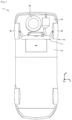
- FIG. 1 a very schematic view is shown from below of the floor of a motor vehicle, referenced 1 as a whole, comprising a rear part 2 comprising a first compartment 3 configured to receive a fuel tank 4 and a second compartment 5, located at the free end of the rear part 2, configured to receive a spare wheel 6 or a liquefied gas tank, with the acronym “LPG”.
- the fuel tank 4 is fixed to side members (not shown) integral with the floor of the vehicle 1, upstream of the second compartment 5, considering the longitudinal axis X.
- the rear part 2 of the vehicle 1 further comprises a rear axle 7 fixed to the lower surface of the floor and to which the rear wheels 8 of the vehicle are connected.
- the rear part 2 of the motor vehicle 1 further comprises a protective assembly 30 fixed to the lower surface of the floor and separating the fuel tank 4 from the second compartment 5 intended to house the spare wheel 6 or an LPG tank.
- the protection assembly 30 is configured to absorb the energy of a rear impact and thus prevent the spare wheel or the LPG tank from coming into contact with the fuel tank 4.
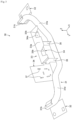
- the protection assembly 30 comprises a protection member 31 of tubular shape comprising a base 31a extending along the transverse axis Y and two attachment portions 31b, 31c to the floor of the vehicle 1.
- the two attachment portions 31b, 31c each extend in a longitudinal direction, opposite to the direction of the longitudinal axis X, that is to say extending towards the front of the vehicle 1.
- the two fixing portions 31b, 31c are parallel to each other.
- the two fixing portions 31b, 31c are connected to the base 31a respectively by a connecting portion 31d, 31e extending in a direction inclined along the vertical axis Z and the transverse axis Y.
- the connecting portions 31d, 31e may have, in a non-limiting manner, one or more curvatures.
- the protective tube 31 forms a shock limiter configured to limit the aggression of the spare wheel 6 or the LPG tank on the fuel tank 4 during an impact at the rear of the vehicle.
- the protective tube 31 is hollow and comprises a wall with a thickness of between 1.5 mm and 2.5 mm, preferably equal to 2 mm.
- the protection assembly 30 comprises two fixing reinforcements 32 secured to the free ends of the protection tube 31, respectively to a fixing portion 31b, 31c and comprising through holes 32a for fixing by screws (not shown) on the lower surface of the floor of the vehicle 1.
- the fixing reinforcements 32 are each in the form of a plate extending in a plane YX comprising the longitudinal axis X and the transverse axis Y.
- Each fixing reinforcement 32 is, here, fixed on the lower surface of the corresponding fixing portion 31b, 31c of the protection tube 31. Alternatively, it could be provided to fix the reinforcements of fixing on the upper surface of the corresponding fixing portion 31b, 31c.
- the protection assembly 30 further comprises a support 33 intended to support both a fuel vapor tank 8, known as a canister in Anglo-Saxon terms, and a particle filter 9.
- the fuel vapor tank 8 has the function of storing fuel vapors from the fuel tank before being returned to the fuel circuit, thus preventing any escape into the atmosphere.
- the dust filter 9 prevents dust from entering the air so as not to damage the pump (not shown) of the fuel tank 4.
- the support 33 therefore makes it possible to hold the fuel vapor tank 8 and the dust filter 9, not requiring additional parts in the motor vehicle.
- the protective tube 31 also protects the fuel vapor tank 8 and the dust filter 9 in the event of an impact at the rear of the vehicle.
- the support 33 comprises a transverse fixing base 34 extending in a plane YZ comprising the vertical axis and the transverse axis, and a longitudinal fixing portion 33a extending in a plane XY comprising the longitudinal axis X and the transverse axis Y, from an upper end of the transverse fixing base 34 towards the rear of the vehicle.
- the longitudinal fixing portion 33a here comprises longitudinal notches 33b.
- the transverse fixing base 34 comprises a first portion 34a for fixing the dust filter 9 and a second portion 34b for fixing the fuel vapor tank 8.
- the first fixing portion 34a comprises a drilling 36, visible on the Figure 2A , intended to receive a screw element 36a for fixing the dust filter 9.
- the second fixing portion 34b comprises a plurality of through grooves 37, visible in the figure 3 , for fixing by screws (not shown) of the fuel vapor tank 8.
- the grooves 37 extend, here, along the vertical axis Z and along the transverse axis Y.
- a drilling or another configuration of grooves could be provided for fixing the fuel vapor tank 8.
- the second fixing portion 34b has a width in the transverse direction Y less than the width of the first portion 34a.
- the width of the first fixing portion 34a is substantially equal to the width of the longitudinal fixing portion 33a.
- the second fixing portion 34b has a height in the vertical direction Z greater than the height of the first portion 34a.
- the protection assembly 30 further comprises two connecting elements 35 extending along the vertical axis Z and configured to connect the support 33 to the protection tube 31.
- the fixing reinforcements 32 are preferably fixed by welding to the protection tube 31 and the connecting elements 35 are fixed by welding respectively to the support 33 and to the protection tube 31.
- the protective assembly has the function of both protecting against an impact at the rear of the vehicle and supporting the dust filter 9 and the fuel vapor tank 8.
- All parts forming the protective assembly are made of metal, for example steel.
- the protection assembly is mounted directly to the underside of the vehicle floor and does not require the addition of additional parts, which reduces the mass of the protection assembly.
- the protective assembly it is possible to reduce the deformation of the fuel tank, and consequently to reduce the risks of fire in the event of an impact at the rear of the vehicle, while making it possible to improve the compactness of the rear part of the vehicle by directly integrating on said protective assembly, a support dedicated to both the fixing of the fuel vapor tank and the dust filter, which further reduces the mass of the vehicle.
- the protective assembly according to the invention also makes it possible to protect the fuel vapor tank and the dust filter in the event of an impact at the rear of the vehicle.
Landscapes
- Engineering & Computer Science (AREA)
- Chemical & Material Sciences (AREA)
- Combustion & Propulsion (AREA)
- Transportation (AREA)
- Mechanical Engineering (AREA)
- Life Sciences & Earth Sciences (AREA)
- Sustainable Development (AREA)
- Sustainable Energy (AREA)
- Cooling, Air Intake And Gas Exhaust, And Fuel Tank Arrangements In Propulsion Units (AREA)
Abstract
Véhicule automobile comprenant un plancher s'étendant selon un axe longitudinal (X), comportant un ensemble (30) de protection fixé sur la surface inférieure d'un plancher du véhicule.L'ensemble (30) de protection comprend :- un organe de protection (31) de forme tubulaire s'étendant selon un axe transversal (Y) perpendiculaire à l'axe longitudinal (X),- deux renforts de fixation (32) solidaires des extrémités libres à l'organe de protection (31), et comportant une interface de fixation (32a) pour la fixation par visseries sur la surface inférieure du plancher du véhicule,- un support (33) configuré pour supporter à la fois un réservoir de vapeurs de carburant (8) relié au réservoir de carburant, et un filtre à particules (9), et- au moins un élément de liaison (35) s'étendant selon un axe vertical (Z) perpendiculaire à l'axe transversal (Y) et à l'axe longitudinal (X) reliant le support (33) à l'organe de protection (31).
Description
- La présente invention concerne le domaine des véhicules automobiles et notamment la structure arrière d'un véhicule automobile.
- Plus particulièrement, la présente invention concerne les systèmes de protection d'un réservoir à carburant présent dans un véhicule automobile, notamment lors d'un choc arrière.
- Généralement, un véhicule automobile comprend une roue de secours ou un réservoir de gaz liquéfié logé dans un compartiment dédié sous le plancher du véhicule, entre l'extrémité arrière du véhicule, dans le sens de circulation du véhicule en marche avant, et l'essieu arrière du véhicule.
- Le réservoir de carburant du véhicule est généralement situé sous le plancher du véhicule à proximité de l'essieu arrière et du compartiment dédié à la roue de secours.
- Les solutions actuelles ne permettent pas de protéger efficacement le réservoir à carburant lors d'un choc arrière tout en respectant les exigences d'homologation.
- Ainsi, il existe un besoin d'améliorer les systèmes de protection du réservoir à carburant de véhicule automobile.
- L'objectif de l'invention est donc de pallier ces inconvénients et d'améliorer les systèmes de protection du réservoir à carburant de véhicule automobile, afin de permettre une implantation aisée, tout en réduisant les coûts de conception et de montage.
- La présente invention a pour objet un véhicule automobile comprenant un plancher s'étendant selon un axe longitudinal, comportant un premier compartiment de réception d'un réservoir de carburant et un deuxième compartiment de réception d'une roue arrière ou d'un réservoir de gaz liquéfié situé en aval du premier compartiment, et un ensemble de protection fixé sur la surface inférieure du plancher du véhicule dans le deuxième compartiment en amont du deuxième compartiment.
- L'ensemble de protection comprend :
- un organe de protection ou tube de protection de forme tubulaire s'étendant selon un axe transversal perpendiculaire à l'axe longitudinal,
- deux renforts de fixation solidaires des extrémités libres à l'organe de protection, notamment respectivement d'une portion de fixation, et comportant une interface de fixation, tel que par exemple des orifices traversants, pour la fixation par visseries sur la surface inférieure du plancher du véhicule,
- un support configuré pour supporter à la fois un réservoir de vapeurs de carburant relié au réservoir de carburant, connu sous le nom de canister en termes anglo-saxons et un filtre à particules, et
- au moins un élément de liaison s'étendant selon un axe vertical perpendiculaire à l'axe transversal et à l'axe longitudinal reliant le support à l'organe de protection.
- L'ensemble de protection a pour fonction à la fois de protéger d'un choc à l'arrière du véhicule et de supporter le filtre à poussières et le réservoir de vapeurs de carburant.
- L'ensemble de protection est configuré pour absorber l'énergie d'un choc arrière et ainsi éviter à la roue de secours ou au réservoir de GPL de venir en contact avec le réservoir à carburant.
- Le tube de protection forme un limiteur de choc configuré pour limiter l'agression de la roue de secours ou du réservoir de GPL sur le réservoir de carburant lors d'un choc à l'arrière du véhicule. Le tube de protection permet également de protéger le réservoir de vapeurs de carburant et le filtre à poussières lors d'un choc à l'arrière du véhicule.
- Le support permet de maintenir le réservoir de vapeurs de carburant et le filtre à poussières, ne nécessitant pas de pièces supplémentaires dans le véhicule automobile.
- Avantageusement, toutes les pièces formant l'ensemble de protection forment ensemble un ensemble monolithique dans lequel toutes les pièces sont fixées de manière irréversibles entre elles.
- En d'autres termes, les renforts de fixation sont, de préférence, fixés par soudage au tube de protection et les éléments de liaison sont fixés par soudage respectivement au support et au tube de protection.
- Avantageusement, l'organe de protection comprend une embase s'étendant selon l'axe transversal et deux portions de fixation au plancher du véhicule, lesdites portions de fixation s'étendant chacune selon la direction longitudinale, opposée à la direction de l'axe longitudinal, c'est-à-dire s'étendant vers l'avant du véhicule.
- Par exemple, les deux portions de fixation de l'organe de protection sont parallèles entre elles.
- Les deux portions de fixation de l'organe de protection peuvent être reliées à l'embase respectivement par une portion de liaison s'étendant selon une direction inclinée selon l'axe vertical et l'axe transversal.
- Par exemple, les portions de liaison peuvent avoir, de manière nullement limitative, une ou plusieurs courbures.
- Par exemple, le tube de protection est creux et comprend une paroi d'épaisseur comprise entre 1.5mm et 2.5mm, de préférence égale à 2mm.
- Avantageusement, les renforts de fixation se présentent chacun sous la forme d'une plaque s'étendant dans un premier plan comprenant l'axe longitudinal et l'axe transversal.
- Par exemple, chaque renfort de fixation est fixé sur la surface inférieure de la portion de fixation correspondante du tube de protection. En variante, on pourrait prévoir de fixer les renforts de fixation sur la surface supérieure de la portion de fixation correspondante.
- Les renforts de fixation sont, de préférence, fixés par soudage au tube de protection.
- Avantageusement, le support comprend une embase de fixation transversale s'étendant dans un deuxième plan comprenant l'axe vertical et l'axe transversal, et une portion de fixation longitudinale s'étendant dans un troisième plan comprenant l'axe longitudinal et l'axe transversal à partir d'une extrémité supérieure de l'embase de fixation transversale vers l'arrière du véhicule.
- Par exemple, la portion de fixation longitudinale comprend des encoches longitudinales.
- Par exemple, l'embase de fixation transversale comprend une première portion comprenant une première interface de fixation, par exemple un perçage coopérant avec des visseries, pour la fixation du filtre à poussières et une deuxième portion comprenant une deuxième interface de fixation, par exemple une pluralité de rainures débouchantes coopérant avec des visseries, pour la fixation du réservoir de vapeurs de carburant.
- La deuxième portion de fixation présente, de préférence, une largeur selon la direction transversale inférieure à la largeur de la première portion et une hauteur selon la direction verticale supérieure à la hauteur de la première portion.
- Par exemple, la largeur de la première portion de fixation est sensiblement égale à la largeur de la portion de fixation longitudinale.
- Selon un autre mode de réalisation, l'ensemble de protection comprend en outre deux éléments de liaison parallèles entre eux, s'étendant selon l'axe vertical et reliant le support au tube de protection.
- D'autres buts, caractéristiques et avantages de l'invention apparaîtront à la lecture de la description suivante, donnée uniquement à titre d'exemple non limitatif, et faite en référence aux dessins annexés sur lesquels :
- [
Fig. 1 ]
illustre de manière très schématique une vue de dessous d'un véhicule automobile comprenant un ensemble de protection du réservoir à carburant selon l'invention ; - [
Fig. 1A ]
est une de détails de lafigure 1 ; - [
Fig.2 ]
représente en détails l'ensemble de protection du réservoir à carburant de lafigure 1 ; - [
Fig.2A ]
illustre en détails la fixation d'un filtre à poussière sur l'ensemble de protection de lafigure 2 ; - [
Fig.2B ]
illustre en détails la fixation d'un réservoir à vapeurs de carburant sur l'ensemble de protection de lafigure 2 ; et - [
Fig. 3 ]
représente en perspective de l'ensemble de protection du réservoir à carburant de lafigure 2 , seul. - Dans la description qui suit, les termes « longitudinal », « transversal », « vertical », « avant », « arrière », « gauche » et « droite » sont définis selon le repère orthogonal habituel des véhicules à moteur, représenté sur les dessins, et qui comprend :
- un axe longitudinal X, horizontal et orienté de l'avant vers l'arrière du véhicule ;
- un axe transversal Y, horizontal, perpendiculaire à l'axe longitudinal X et orienté de la gauche vers la droite du véhicule quand le véhicule avance ;
- un axe vertical Z, orthogonal aux axes longitudinal et transversal X et Y et dirigé de bas en haut.
- Sur la
figure 1 , on a représenté de manière très schématique une vue de dessous du plancher d'un véhicule automobile, référencé 1 dans son ensemble, comprenant une partie arrière 2 comprenant un premier compartiment 3 configuré pour recevoir un réservoir à carburant 4 et un deuxième compartiment 5, situé à l'extrémité libre de la partie arrière 2, configuré pour recevoir une roue de secours 6 ou un réservoir de gaz liquéfié, d'acronyme « GPL ». - De manière connue en soi, le réservoir de carburant 4 est fixé sur des longerons (non représentés) solidaires du plancher du véhicule 1, en amont du deuxième compartiment 5, en considérant l'axe longitudinal X.
- De manière connue en soi, la partie arrière 2 du véhicule 1 comprend en outre un essieu arrière 7 fixé sur la surface inférieure du plancher et auquel sont reliées les roues arrière 8 du véhicule.
- La partie arrière 2 du véhicule automobile 1 comprend en outre un ensemble 30 de protection fixé sur la surface inférieure du plancher et séparant le réservoir de carburant 4 du deuxième compartiment 5 destiné à loger la roue de secours 6 ou un réservoir de GPL.
- L'ensemble 30 de protection est configuré pour absorber l'énergie d'un choc arrière et ainsi éviter à la roue de secours ou au réservoir de GPL de venir en contact avec le réservoir à carburant 4.
- A cet effet, l'ensemble 30 de protection comprend un organe de protection 31 de forme tubulaire comprenant une embase 31a s'étendant selon l'axe transversal Y et deux portions de fixation 31b, 31c au plancher du véhicule 1. Les deux portions de fixation 31b, 31c s'étendent chacune selon une direction longitudinale, opposée à la direction de l'axe longitudinal X, c'est-à-dire s'étendant vers l'avant du véhicule 1.
- Les deux portions de fixation 31b, 31c sont parallèles entre elles.
- Les deux portions de fixation 31b, 31c sont reliées à l'embase 31a respectivement par une portion de liaison 31d, 31e s'étendant selon une direction inclinée selon l'axe vertical Z et l'axe transversal Y.
- Les portions de liaison 31d, 31e peuvent avoir, de manière nullement limitative, une ou plusieurs courbures.
- Le tube de protection 31 forme un limiteur de choc configuré pour limiter l'agression de la roue de secours 6 ou du réservoir de GPL sur le réservoir de carburant 4 lors d'un choc à l'arrière du véhicule.
- Le tube de protection 31 est creux et comprend une paroi d'épaisseur comprise entre 1.5mm et 2.5mm, de préférence égale à 2mm.
- L'ensemble 30 de protection comprend deux renforts de fixation 32 solidaires des extrémités libres du tube de protection 31, respectivement d'une portion de fixation 31b, 31c et comportant des orifices traversants 32a pour la fixation par visseries (non représentées) sur la surface inférieure du plancher du véhicule 1.
- Les renforts de fixation 32 se présentent chacun sous la forme d'une plaque s'étendant dans un plan YX comprenant l'axe longitudinal X et l'axe transversal Y.
- Chaque renfort de fixation 32 est, ici, fixé sur la surface inférieure de la portion de fixation correspondante 31b, 31c du tube de protection 31. En variante, on pourrait prévoir de fixer les renforts de fixation sur la surface supérieure de la portion de fixation correspondante 31b, 31c.
- L'ensemble 30 de protection comprend en outre un support 33 destiné à supporter à la fois un réservoir de vapeurs de carburant 8, connu sous le nom de canister en termes anglo-saxons et un filtre à particules 9.
- Le réservoir de vapeurs de carburant 8 a pour fonction de stocker les vapeurs de carburant issues du réservoir à carburant avant d'être renvoyées dans le circuit de carburant, évitant ainsi tout échappement dans l'atmosphère.
- Le filtre à poussières 9 permet d'éviter l'entrée des poussières dans l'air afin de ne pas détériorer la pompe (non représentée) du réservoir à carburant 4.
- Le support 33 permet donc de maintenir le réservoir de vapeurs de carburant 8 et le filtre à poussières 9, ne nécessitant pas de pièces supplémentaires dans le véhicule automobile.
- Le tube de protection 31 permet également de protéger le réservoir de vapeurs de carburant 8 et le filtre à poussières 9 lors d'un choc à l'arrière du véhicule.
- Le support 33 comprend une embase de fixation transversale 34 s'étendant dans un plan YZ comprenant l'axe vertical et l'axe transversal, et une portion de fixation longitudinale 33a s'étendant dans un plan XY comprenant l'axe longitudinal X et l'axe transversal Y, à partir d'une extrémité supérieure de l'embase de fixation transversale 34 vers l'arrière du véhicule.
- La portion de fixation longitudinale 33a comprend, ici, des encoches longitudinales 33b.
- L'embase de fixation transversale 34 comprend une première portion 34a de fixation du filtre à poussières 9 et une deuxième portion 34b de fixation du réservoir de vapeurs de carburant 8.
- La première portion 34a de fixation comprend un perçage 36, visible sur la
figure 2A , destiné à recevoir un élément de visserie 36a pour la fixation du filtre à poussières 9. - La deuxième portion 34b de fixation comprend une pluralité de rainures débouchantes 37, visibles sur la
figure 3 , pour la fixation par visseries (non représentée) du réservoir de vapeurs de carburant 8. - Les rainures 37 s'étendent, ici, selon l'axe vertical Z et selon l'axe transversal Y. en variante, on pourrait prévoir un perçage ou une autre configuration de rainures pour la fixation du réservoir de vapeurs de carburant 8.
- La deuxième portion 34b de fixation présente une largeur selon la direction transversale Y inférieure à la largeur de la première portion 34a.
- La largeur de la première portion 34a de fixation est sensiblement égale à la largeur de la portion de fixation longitudinale 33a.
- La deuxième portion 34b de fixation présente une hauteur selon la direction verticale Z supérieure à la hauteur de la première portion 34a.
- L'ensemble 30 de protection comprend en outre deux éléments de liaison 35 s'étendant selon l'axe vertical Z et configurés pour relier le support 33 au tube de protection 31.
- Les renforts de fixation 32 sont, de préférence, fixés par soudage au tube de protection 31 et les éléments de liaison 35 sont fixés par soudage respectivement au support 33 et au tube de protection 31.
- En d'autres termes, toutes les pièces formant l'ensemble de protection forment ensemble un ensemble monolithique dans lequel toutes les pièces sont fixées de manière irréversibles entre elles.
- L'ensemble de protection a pour fonction à la fois de protéger d'un choc à l'arrière du véhicule et de supporter le filtre à poussières 9 et le réservoir de vapeurs de carburant 8.
- Toutes les pièces formant l'ensemble de protection sont réalisées en matière métallique, par exemple en acier.
- L'ensemble de protection est monté directement sur la surface inférieure du plancher du véhicule et ne nécessite pas l'ajout de pièces supplémentaires, ce qui réduit la masse de l'ensemble de protection.
- Grâce à l'ensemble de protection selon l'invention, il est possible de diminuer la déformation du réservoir de carburant, et par conséquent de réduire les risques d'incendie en cas de choc à l'arrière du véhicule, tout en permettant d'améliorer la compacité de la partie arrière du véhicule en intégrant directement sur ledit ensemble de protection, d'un support dédié à la fois à la fixation du réservoir de vapeurs de carburant et du filtre à poussières, ce qui réduit davantage la masse du véhicule.
- Par ailleurs, l'ensemble de protection selon l'invention permet également de protéger le réservoir de vapeurs de carburant et le filtre à poussières lors d'un choc à l'arrière du véhicule.
Claims (10)
- Véhicule automobile (1) comprenant un plancher s'étendant selon un axe longitudinal (X), comportant un premier compartiment (3) de réception d'un réservoir de carburant (4) et un deuxième compartiment (5) de réception d'une roue arrière (6) ou d'un réservoir de gaz liquéfié situé en aval du premier compartiment (3), et un ensemble (30) de protection fixé sur la surface inférieure du plancher du véhicule dans le deuxième compartiment (5) en amont du deuxième compartiment (5), caractérisé en ce que l'ensemble (30) de protection comprend :- un organe de protection (31) de forme tubulaire s'étendant selon un axe transversal (Y) perpendiculaire à l'axe longitudinal (X),- deux renforts de fixation (32) solidaires des extrémités libres à l'organe de protection (31), et comportant une interface de fixation (32a) pour la fixation par visseries sur la surface inférieure du plancher du véhicule (1),- un support (33) configuré pour supporter à la fois un réservoir de vapeurs de carburant (8) relié au réservoir de carburant (4), et un filtre à particules (9), et- au moins un élément de liaison (35) s'étendant selon un axe vertical (Z) perpendiculaire à l'axe transversal (Y) et à l'axe longitudinal (X) reliant le support (33) à l'organe de protection (31).
- Véhicule automobile (1) selon la revendication 1, dans lequel toutes les pièces formant l'ensemble de protection (30) forment ensemble un ensemble monolithique dans lequel toutes les pièces sont fixées de manière irréversibles entre elles.
- Véhicule automobile (1) selon la revendication 1 ou 2, dans lequel l'organe de protection (31) comprend une embase (31a) s'étendant selon l'axe transversal (Y) et deux portions de fixation (31b, 31c) au plancher du véhicule (1), lesdites portions de fixation (31b, 31c) s'étendant chacune selon la direction longitudinale, opposée à la direction de l'axe longitudinal (X).
- Véhicule automobile (1) selon la revendication 3, dans lequel les deux portions de fixation (31b, 31c) de l'organe de protection (31) sont parallèles entre elles.
- Véhicule automobile (1) selon la revendication 3 ou 4, dans lequel les deux portions de fixation (31b, 31c) de l'organe de protection (31) sont reliées à l'embase (31a) respectivement par une portion de liaison (31d, 31e) s'étendant selon une direction inclinée selon l'axe vertical (Z) et l'axe transversal (Y).
- Véhicule automobile (1) selon l'une quelconque des revendications précédentes, dans lequel les renforts de fixation (32) se présentent chacun sous la forme d'une plaque s'étendant dans un premier plan (YX) comprenant l'axe longitudinal (X) et l'axe transversal (Y).
- Véhicule automobile (1) selon l'une quelconque des revendications précédentes, dans lequel le support (33) comprend une embase de fixation transversale (34) s'étendant dans un deuxième plan (YZ) comprenant l'axe vertical (Z) et l'axe transversal (Y), et une portion de fixation longitudinale (33a) s'étendant dans un troisième plan (XY) comprenant l'axe longitudinal (X) et l'axe transversal (Y) à partir d'une extrémité supérieure de l'embase de fixation transversale (34) vers l'arrière du véhicule.
- Véhicule automobile (1) selon la revendication 7, dans lequel l'embase de fixation transversale (34) comprend une première portion (34a) comprenant une première interface de fixation pour la fixation du filtre à poussières (9) et une deuxième portion (34b) comprenant une deuxième interface de fixation pour la fixation du réservoir de vapeurs de carburant (8).
- Véhicule automobile (1) selon la revendication 7 ou 8, dans lequel la deuxième portion (34b) de fixation présente une largeur selon la direction transversale (Y) inférieure à la largeur de la première portion (34a) et une hauteur selon la direction verticale (Z) supérieure à la hauteur de la première portion (34a).
- Véhicule automobile (1) selon l'une quelconque des revendications précédentes, dans lequel l'ensemble (30) de protection comprend en outre deux éléments de liaison (35) parallèles entre eux, s'étendant selon l'axe vertical (Z) et reliant le support (33) au tube de protection (31).
Applications Claiming Priority (1)
| Application Number | Priority Date | Filing Date | Title |
|---|---|---|---|
| FR2305748A FR3149582B1 (fr) | 2023-06-07 | 2023-06-07 | Véhicule automobile comprenant un ensemble de protection du réservoir de carburant |
Publications (1)
| Publication Number | Publication Date |
|---|---|
| EP4474255A1 true EP4474255A1 (fr) | 2024-12-11 |
Family
ID=88068597
Family Applications (1)
| Application Number | Title | Priority Date | Filing Date |
|---|---|---|---|
| EP24178603.7A Pending EP4474255A1 (fr) | 2023-06-07 | 2024-05-28 | Véhicule automobile comprenant un ensemble de protection du réservoir de carburant |
Country Status (2)
| Country | Link |
|---|---|
| EP (1) | EP4474255A1 (fr) |
| FR (1) | FR3149582B1 (fr) |
Citations (7)
| Publication number | Priority date | Publication date | Assignee | Title |
|---|---|---|---|---|
| US20040075269A1 (en) * | 2002-10-22 | 2004-04-22 | Honda Giken Kogyo Kabushiki Kaisha | Canister mounting structure |
| JP2006160044A (ja) * | 2004-12-06 | 2006-06-22 | Nissan Motor Co Ltd | 車両のキャニスタ配設構造 |
| EP2143584A1 (fr) * | 2008-07-07 | 2010-01-13 | Honda Motor Co., Ltd. | Structure de montage de réservoir véhiculaire |
| DE102009035857A1 (de) * | 2008-08-08 | 2010-03-25 | Suzuki Motor Corp., Hamamatsu-Shi | Auffangbehälter-Montagestruktur |
| EP3626590A1 (fr) * | 2018-09-21 | 2020-03-25 | RENAULT s.a.s. | Véhicule automobile comprenant une barrière de protection d'un reservoir a carburant |
| EP3792153A1 (fr) * | 2019-09-11 | 2021-03-17 | Renault S.A.S. | Déflecteur pour véhicule automobile et véhicule doté d'un tel déflecteur |
| WO2022075282A1 (fr) * | 2020-10-07 | 2022-04-14 | 三菱自動車工業株式会社 | Structure de placement de cartouche pour véhicule |
-
2023
- 2023-06-07 FR FR2305748A patent/FR3149582B1/fr active Active
-
2024
- 2024-05-28 EP EP24178603.7A patent/EP4474255A1/fr active Pending
Patent Citations (7)
| Publication number | Priority date | Publication date | Assignee | Title |
|---|---|---|---|---|
| US20040075269A1 (en) * | 2002-10-22 | 2004-04-22 | Honda Giken Kogyo Kabushiki Kaisha | Canister mounting structure |
| JP2006160044A (ja) * | 2004-12-06 | 2006-06-22 | Nissan Motor Co Ltd | 車両のキャニスタ配設構造 |
| EP2143584A1 (fr) * | 2008-07-07 | 2010-01-13 | Honda Motor Co., Ltd. | Structure de montage de réservoir véhiculaire |
| DE102009035857A1 (de) * | 2008-08-08 | 2010-03-25 | Suzuki Motor Corp., Hamamatsu-Shi | Auffangbehälter-Montagestruktur |
| EP3626590A1 (fr) * | 2018-09-21 | 2020-03-25 | RENAULT s.a.s. | Véhicule automobile comprenant une barrière de protection d'un reservoir a carburant |
| EP3792153A1 (fr) * | 2019-09-11 | 2021-03-17 | Renault S.A.S. | Déflecteur pour véhicule automobile et véhicule doté d'un tel déflecteur |
| WO2022075282A1 (fr) * | 2020-10-07 | 2022-04-14 | 三菱自動車工業株式会社 | Structure de placement de cartouche pour véhicule |
Also Published As
| Publication number | Publication date |
|---|---|
| FR3149582A1 (fr) | 2024-12-13 |
| FR3149582B1 (fr) | 2025-11-21 |
Similar Documents
| Publication | Publication Date | Title |
|---|---|---|
| EP2834104B1 (fr) | Châssis d'un véhicule automobile comprenant des moyens d'absorption d'un choc frontal | |
| WO2010081997A2 (fr) | Chassis de vehicule avec logement de dispositif de stockage d'energie | |
| FR3023233A1 (fr) | Support pour la fixation d'un boitier electronique et d'un ecran thermique | |
| FR3083513A1 (fr) | Agencement d'un soubassement de caisse d'un vehicule integrant un ensemble de batteries et vehicule ayant un tel agencement | |
| FR2887508A1 (fr) | Poutre d'absorption d'energie, notamment pour vehicule automobile, et vehicule automobile equipe d'une telle poutre | |
| FR3081817A1 (fr) | Support de batterie modulable pour la protection en cas de choc arriere | |
| EP4474255A1 (fr) | Véhicule automobile comprenant un ensemble de protection du réservoir de carburant | |
| EP3877238B1 (fr) | Dispositif de protection d'une batterie d'alimentation de puissance d'un véhicule | |
| FR3123042A1 (fr) | Dispositif de protection de la batterie des véhicules automobiles hybrides contre les chocs arrière à grande vitesse | |
| FR3058365A1 (fr) | Support pour batterie multifonction | |
| FR3105151A1 (fr) | Structure arriere de caisse de vehicule automobile a plancher polymere et support de batterie | |
| WO2019197748A1 (fr) | Dispositif de maintien securise et de protection thermique d'elements | |
| EP2978658B1 (fr) | Ensemble pour châssis comportant un réservoir de stockage d'un agent de dépollution et véhicule automobile correspondant | |
| FR3036664A1 (fr) | Ensemble sous-plancher arriere d’un vehicule automobile comprenant un dispositif de recyclage des vapeurs de carburant | |
| FR3120093A1 (fr) | Support de bloc électrique comprenant une suspente pour une ligne d’échappement | |
| FR3104123A1 (fr) | Plancher avec protection de batterie sous siège avant. | |
| FR2901748A1 (fr) | Agencement d'un silencieux d'un vehicule automobile, au sein d'un longeron du vehicule, longeron associe | |
| FR2879515A1 (fr) | Dispositif de fixation d'un groupe motopropulseur a un chassis de vehicule | |
| FR3120578A1 (fr) | Support d’un chargeur de batterie électrique d’un véhicule automobile | |
| FR3154352A1 (fr) | Architecture d’un circuit d’alimentation en carburant d’un groupe motopropulseur au sein d’un compartiment moteur d’un véhicule automobile. | |
| FR3163907A1 (fr) | Vehicule automobile comprenant un ecran de protection de batterie equipe d’une cage de protection de connecteur, et procede de fabrication d’un tel vehicule | |
| WO2024121472A1 (fr) | Fixation de bras de suspension à un longeron de structure de véhicule automobile | |
| FR3130699A1 (fr) | Dispositif de maintien d’au moins un élément de stockage d’énergie agencé sous le plancher d’un véhicule automobile | |
| WO2022243613A1 (fr) | Dispositif de renfort de train arriere de vehicule, notamment automobile. | |
| EP4506234A1 (fr) | Structure de véhicule automobile avec planche à talon |
Legal Events
| Date | Code | Title | Description |
|---|---|---|---|
| PUAI | Public reference made under article 153(3) epc to a published international application that has entered the european phase |
Free format text: ORIGINAL CODE: 0009012 |
|
| STAA | Information on the status of an ep patent application or granted ep patent |
Free format text: STATUS: THE APPLICATION HAS BEEN PUBLISHED |
|
| AK | Designated contracting states |
Kind code of ref document: A1 Designated state(s): AL AT BE BG CH CY CZ DE DK EE ES FI FR GB GR HR HU IE IS IT LI LT LU LV MC ME MK MT NL NO PL PT RO RS SE SI SK SM TR |
|
| STAA | Information on the status of an ep patent application or granted ep patent |
Free format text: STATUS: REQUEST FOR EXAMINATION WAS MADE |
|
| 17P | Request for examination filed |
Effective date: 20250519 |