EP4474208A1 - In-vehicle control device - Google Patents
In-vehicle control device Download PDFInfo
- Publication number
- EP4474208A1 EP4474208A1 EP24163188.6A EP24163188A EP4474208A1 EP 4474208 A1 EP4474208 A1 EP 4474208A1 EP 24163188 A EP24163188 A EP 24163188A EP 4474208 A1 EP4474208 A1 EP 4474208A1
- Authority
- EP
- European Patent Office
- Prior art keywords
- proportion
- charging
- storage
- necessary
- charging time
- Prior art date
- Legal status (The legal status is an assumption and is not a legal conclusion. Google has not performed a legal analysis and makes no representation as to the accuracy of the status listed.)
- Pending
Links
Images

Classifications
-
- B—PERFORMING OPERATIONS; TRANSPORTING
- B60—VEHICLES IN GENERAL
- B60L—PROPULSION OF ELECTRICALLY-PROPELLED VEHICLES; SUPPLYING ELECTRIC POWER FOR AUXILIARY EQUIPMENT OF ELECTRICALLY-PROPELLED VEHICLES; ELECTRODYNAMIC BRAKE SYSTEMS FOR VEHICLES IN GENERAL; MAGNETIC SUSPENSION OR LEVITATION FOR VEHICLES; MONITORING OPERATING VARIABLES OF ELECTRICALLY-PROPELLED VEHICLES; ELECTRIC SAFETY DEVICES FOR ELECTRICALLY-PROPELLED VEHICLES
- B60L53/00—Methods of charging batteries, specially adapted for electric vehicles; Charging stations or on-board charging equipment therefor; Exchange of energy storage elements in electric vehicles
- B60L53/60—Monitoring or controlling charging stations
- B60L53/66—Data transfer between charging stations and vehicles
- B60L53/665—Methods related to measuring, billing or payment
-
- H—ELECTRICITY
- H02—GENERATION; CONVERSION OR DISTRIBUTION OF ELECTRIC POWER
- H02J—ELECTRIC POWER NETWORKS; CIRCUIT ARRANGEMENTS OR SYSTEMS FOR SUPPLYING OR DISTRIBUTING ELECTRIC POWER; SYSTEMS FOR STORING ELECTRIC ENERGY
- H02J7/00—Circuit arrangements for charging or discharging batteries or for supplying loads from batteries
- H02J7/80—Circuit arrangements for charging or discharging batteries or for supplying loads from batteries including monitoring or indicating arrangements
-
- B—PERFORMING OPERATIONS; TRANSPORTING
- B60—VEHICLES IN GENERAL
- B60W—CONJOINT CONTROL OF VEHICLE SUB-UNITS OF DIFFERENT TYPE OR DIFFERENT FUNCTION; CONTROL SYSTEMS SPECIALLY ADAPTED FOR HYBRID VEHICLES; ROAD VEHICLE DRIVE CONTROL SYSTEMS FOR PURPOSES NOT RELATED TO THE CONTROL OF A PARTICULAR SUB-UNIT
- B60W50/00—Details of control systems for road vehicle drive control not related to the control of a particular sub-unit, e.g. process diagnostic or vehicle driver interfaces
- B60W50/08—Interaction between the driver and the control system
- B60W50/14—Means for informing the driver, warning the driver or prompting a driver intervention
-
- B—PERFORMING OPERATIONS; TRANSPORTING
- B60—VEHICLES IN GENERAL
- B60K—ARRANGEMENT OR MOUNTING OF PROPULSION UNITS OR OF TRANSMISSIONS IN VEHICLES; ARRANGEMENT OR MOUNTING OF PLURAL DIVERSE PRIME-MOVERS IN VEHICLES; AUXILIARY DRIVES FOR VEHICLES; INSTRUMENTATION OR DASHBOARDS FOR VEHICLES; ARRANGEMENTS IN CONNECTION WITH COOLING, AIR INTAKE, GAS EXHAUST OR FUEL SUPPLY OF PROPULSION UNITS IN VEHICLES
- B60K35/00—Instruments specially adapted for vehicles; Arrangement of instruments in or on vehicles
- B60K35/20—Output arrangements, i.e. from vehicle to user, associated with vehicle functions or specially adapted therefor
- B60K35/21—Output arrangements, i.e. from vehicle to user, associated with vehicle functions or specially adapted therefor using visual output, e.g. blinking lights or matrix displays
-
- B—PERFORMING OPERATIONS; TRANSPORTING
- B60—VEHICLES IN GENERAL
- B60K—ARRANGEMENT OR MOUNTING OF PROPULSION UNITS OR OF TRANSMISSIONS IN VEHICLES; ARRANGEMENT OR MOUNTING OF PLURAL DIVERSE PRIME-MOVERS IN VEHICLES; AUXILIARY DRIVES FOR VEHICLES; INSTRUMENTATION OR DASHBOARDS FOR VEHICLES; ARRANGEMENTS IN CONNECTION WITH COOLING, AIR INTAKE, GAS EXHAUST OR FUEL SUPPLY OF PROPULSION UNITS IN VEHICLES
- B60K35/00—Instruments specially adapted for vehicles; Arrangement of instruments in or on vehicles
- B60K35/20—Output arrangements, i.e. from vehicle to user, associated with vehicle functions or specially adapted therefor
- B60K35/28—Output arrangements, i.e. from vehicle to user, associated with vehicle functions or specially adapted therefor characterised by the type of the output information, e.g. video entertainment or vehicle dynamics information; characterised by the purpose of the output information, e.g. for attracting the attention of the driver
-
- B—PERFORMING OPERATIONS; TRANSPORTING
- B60—VEHICLES IN GENERAL
- B60K—ARRANGEMENT OR MOUNTING OF PROPULSION UNITS OR OF TRANSMISSIONS IN VEHICLES; ARRANGEMENT OR MOUNTING OF PLURAL DIVERSE PRIME-MOVERS IN VEHICLES; AUXILIARY DRIVES FOR VEHICLES; INSTRUMENTATION OR DASHBOARDS FOR VEHICLES; ARRANGEMENTS IN CONNECTION WITH COOLING, AIR INTAKE, GAS EXHAUST OR FUEL SUPPLY OF PROPULSION UNITS IN VEHICLES
- B60K35/00—Instruments specially adapted for vehicles; Arrangement of instruments in or on vehicles
- B60K35/80—Arrangements for controlling instruments
- B60K35/81—Arrangements for controlling instruments for controlling displays
-
- B—PERFORMING OPERATIONS; TRANSPORTING
- B60—VEHICLES IN GENERAL
- B60L—PROPULSION OF ELECTRICALLY-PROPELLED VEHICLES; SUPPLYING ELECTRIC POWER FOR AUXILIARY EQUIPMENT OF ELECTRICALLY-PROPELLED VEHICLES; ELECTRODYNAMIC BRAKE SYSTEMS FOR VEHICLES IN GENERAL; MAGNETIC SUSPENSION OR LEVITATION FOR VEHICLES; MONITORING OPERATING VARIABLES OF ELECTRICALLY-PROPELLED VEHICLES; ELECTRIC SAFETY DEVICES FOR ELECTRICALLY-PROPELLED VEHICLES
- B60L58/00—Methods or circuit arrangements for monitoring or controlling batteries or fuel cells, specially adapted for electric vehicles
- B60L58/10—Methods or circuit arrangements for monitoring or controlling batteries or fuel cells, specially adapted for electric vehicles for monitoring or controlling batteries
- B60L58/12—Methods or circuit arrangements for monitoring or controlling batteries or fuel cells, specially adapted for electric vehicles for monitoring or controlling batteries responding to state of charge [SoC]
- B60L58/13—Maintaining the SoC within a determined range
-
- B—PERFORMING OPERATIONS; TRANSPORTING
- B60—VEHICLES IN GENERAL
- B60W—CONJOINT CONTROL OF VEHICLE SUB-UNITS OF DIFFERENT TYPE OR DIFFERENT FUNCTION; CONTROL SYSTEMS SPECIALLY ADAPTED FOR HYBRID VEHICLES; ROAD VEHICLE DRIVE CONTROL SYSTEMS FOR PURPOSES NOT RELATED TO THE CONTROL OF A PARTICULAR SUB-UNIT
- B60W50/00—Details of control systems for road vehicle drive control not related to the control of a particular sub-unit, e.g. process diagnostic or vehicle driver interfaces
- B60W50/08—Interaction between the driver and the control system
- B60W50/085—Changing the parameters of the control units, e.g. changing limit values, working points by control input
-
- H—ELECTRICITY
- H02—GENERATION; CONVERSION OR DISTRIBUTION OF ELECTRIC POWER
- H02J—ELECTRIC POWER NETWORKS; CIRCUIT ARRANGEMENTS OR SYSTEMS FOR SUPPLYING OR DISTRIBUTING ELECTRIC POWER; SYSTEMS FOR STORING ELECTRIC ENERGY
- H02J7/00—Circuit arrangements for charging or discharging batteries or for supplying loads from batteries
- H02J7/80—Circuit arrangements for charging or discharging batteries or for supplying loads from batteries including monitoring or indicating arrangements
- H02J7/82—Control of state of charge [SOC]
-
- H—ELECTRICITY
- H02—GENERATION; CONVERSION OR DISTRIBUTION OF ELECTRIC POWER
- H02J—ELECTRIC POWER NETWORKS; CIRCUIT ARRANGEMENTS OR SYSTEMS FOR SUPPLYING OR DISTRIBUTING ELECTRIC POWER; SYSTEMS FOR STORING ELECTRIC ENERGY
- H02J7/00—Circuit arrangements for charging or discharging batteries or for supplying loads from batteries
- H02J7/80—Circuit arrangements for charging or discharging batteries or for supplying loads from batteries including monitoring or indicating arrangements
- H02J7/82—Control of state of charge [SOC]
- H02J7/825—Detection of fully charged condition
-
- B—PERFORMING OPERATIONS; TRANSPORTING
- B60—VEHICLES IN GENERAL
- B60K—ARRANGEMENT OR MOUNTING OF PROPULSION UNITS OR OF TRANSMISSIONS IN VEHICLES; ARRANGEMENT OR MOUNTING OF PLURAL DIVERSE PRIME-MOVERS IN VEHICLES; AUXILIARY DRIVES FOR VEHICLES; INSTRUMENTATION OR DASHBOARDS FOR VEHICLES; ARRANGEMENTS IN CONNECTION WITH COOLING, AIR INTAKE, GAS EXHAUST OR FUEL SUPPLY OF PROPULSION UNITS IN VEHICLES
- B60K2360/00—Indexing scheme associated with groups B60K35/00 or B60K37/00 relating to details of instruments or dashboards
- B60K2360/16—Type of output information
- B60K2360/168—Target or limit values
-
- B—PERFORMING OPERATIONS; TRANSPORTING
- B60—VEHICLES IN GENERAL
- B60K—ARRANGEMENT OR MOUNTING OF PROPULSION UNITS OR OF TRANSMISSIONS IN VEHICLES; ARRANGEMENT OR MOUNTING OF PLURAL DIVERSE PRIME-MOVERS IN VEHICLES; AUXILIARY DRIVES FOR VEHICLES; INSTRUMENTATION OR DASHBOARDS FOR VEHICLES; ARRANGEMENTS IN CONNECTION WITH COOLING, AIR INTAKE, GAS EXHAUST OR FUEL SUPPLY OF PROPULSION UNITS IN VEHICLES
- B60K2360/00—Indexing scheme associated with groups B60K35/00 or B60K37/00 relating to details of instruments or dashboards
- B60K2360/16—Type of output information
- B60K2360/169—Remaining operating distance or charge
-
- B—PERFORMING OPERATIONS; TRANSPORTING
- B60—VEHICLES IN GENERAL
- B60L—PROPULSION OF ELECTRICALLY-PROPELLED VEHICLES; SUPPLYING ELECTRIC POWER FOR AUXILIARY EQUIPMENT OF ELECTRICALLY-PROPELLED VEHICLES; ELECTRODYNAMIC BRAKE SYSTEMS FOR VEHICLES IN GENERAL; MAGNETIC SUSPENSION OR LEVITATION FOR VEHICLES; MONITORING OPERATING VARIABLES OF ELECTRICALLY-PROPELLED VEHICLES; ELECTRIC SAFETY DEVICES FOR ELECTRICALLY-PROPELLED VEHICLES
- B60L2240/00—Control parameters of input or output; Target parameters
- B60L2240/80—Time limits
-
- B—PERFORMING OPERATIONS; TRANSPORTING
- B60—VEHICLES IN GENERAL
- B60L—PROPULSION OF ELECTRICALLY-PROPELLED VEHICLES; SUPPLYING ELECTRIC POWER FOR AUXILIARY EQUIPMENT OF ELECTRICALLY-PROPELLED VEHICLES; ELECTRODYNAMIC BRAKE SYSTEMS FOR VEHICLES IN GENERAL; MAGNETIC SUSPENSION OR LEVITATION FOR VEHICLES; MONITORING OPERATING VARIABLES OF ELECTRICALLY-PROPELLED VEHICLES; ELECTRIC SAFETY DEVICES FOR ELECTRICALLY-PROPELLED VEHICLES
- B60L2250/00—Driver interactions
- B60L2250/16—Driver interactions by display
-
- B—PERFORMING OPERATIONS; TRANSPORTING
- B60—VEHICLES IN GENERAL
- B60W—CONJOINT CONTROL OF VEHICLE SUB-UNITS OF DIFFERENT TYPE OR DIFFERENT FUNCTION; CONTROL SYSTEMS SPECIALLY ADAPTED FOR HYBRID VEHICLES; ROAD VEHICLE DRIVE CONTROL SYSTEMS FOR PURPOSES NOT RELATED TO THE CONTROL OF A PARTICULAR SUB-UNIT
- B60W50/00—Details of control systems for road vehicle drive control not related to the control of a particular sub-unit, e.g. process diagnostic or vehicle driver interfaces
- B60W50/08—Interaction between the driver and the control system
- B60W50/14—Means for informing the driver, warning the driver or prompting a driver intervention
- B60W2050/146—Display means
-
- B—PERFORMING OPERATIONS; TRANSPORTING
- B60—VEHICLES IN GENERAL
- B60W—CONJOINT CONTROL OF VEHICLE SUB-UNITS OF DIFFERENT TYPE OR DIFFERENT FUNCTION; CONTROL SYSTEMS SPECIALLY ADAPTED FOR HYBRID VEHICLES; ROAD VEHICLE DRIVE CONTROL SYSTEMS FOR PURPOSES NOT RELATED TO THE CONTROL OF A PARTICULAR SUB-UNIT
- B60W2510/00—Input parameters relating to a particular sub-units
- B60W2510/24—Energy storage means
- B60W2510/242—Energy storage means for electrical energy
- B60W2510/244—Charge state
-
- Y—GENERAL TAGGING OF NEW TECHNOLOGICAL DEVELOPMENTS; GENERAL TAGGING OF CROSS-SECTIONAL TECHNOLOGIES SPANNING OVER SEVERAL SECTIONS OF THE IPC; TECHNICAL SUBJECTS COVERED BY FORMER USPC CROSS-REFERENCE ART COLLECTIONS [XRACs] AND DIGESTS
- Y02—TECHNOLOGIES OR APPLICATIONS FOR MITIGATION OR ADAPTATION AGAINST CLIMATE CHANGE
- Y02T—CLIMATE CHANGE MITIGATION TECHNOLOGIES RELATED TO TRANSPORTATION
- Y02T10/00—Road transport of goods or passengers
- Y02T10/60—Other road transportation technologies with climate change mitigation effect
- Y02T10/70—Energy storage systems for electromobility, e.g. batteries
Definitions
- the present disclosure relates to an in-vehicle control device configured to control charging of a power storage device installed in the vehicle using electric power from an external power source.
- An in-vehicle control device is proposed in which, while a battery installed in a vehicle is being rapidly charged, necessary time that will be required to reach full charge, and necessary time that will be required to reach a predetermined charge state that is lower than full charge, are displayed on a liquid crystal display panel installed in the vehicle (e.g., see Japanese Unexamined Patent Application Publication No. 2012-025211 ( JP 2012-025211 A )).
- a liquid crystal display panel installed in the vehicle.g., see Japanese Unexamined Patent Application Publication No. 2012-025211 ( JP 2012-025211 A )
- displaying the necessary time that will be required to reach full charge and the necessary time that will be required to reach a predetermined charge state on the liquid crystal display panel enables a user to easily check the charge state when charging the battery.
- the necessary time that will be required to reach full charge and the necessary time that will be required to reach a predetermined charge state are displayed on the liquid crystal display panel, and accordingly displayed contents are not simple and may be misread by the user. Also, some users may desire to display just one of the necessary time that will be required to reach full charge and the necessary time that will be required to reach a predetermined charge state.
- the present disclosure provides an in vehicle control device that more appropriately displays necessary time required for charging while a power storage device installed in the vehicle is being charged by electric power from an external power source.
- An in-vehicle control device configured to control charging of a power storage device that is installed in a vehicle, using electric power from an external power source.
- the in-vehicle control device includes a processor.
- the processor is configured to output a first necessary charging time to a display device when a predetermined condition is satisfied while charging the power storage device using the electric power from the external power source.
- the first necessary charging time is an amount of time required for a storage proportion of the power storage device to reach a predetermined storage proportion that is lower than a full-charge proportion.
- the processor is configured to output a second necessary charging time to the display device when the predetermined condition is not satisfied while charging the power storage device using the electric power from the external power source.
- the second necessary charging time is an amount of time required for the storage proportion of the power storage device to reach the full-charge proportion.
- the predetermined condition may be a first condition in which the storage proportion of the power storage device is lower than the predetermined storage proportion.
- the predetermined condition may be a second condition in which the storage proportion of the power storage device is lower than the predetermined storage proportion and also charging is performed using direct current electric power from an external direct current power source.
- the display device may be a mobile terminal of a user.
- the predetermined storage proportion may be a proportion within a range of 70% to 90% as to the full-charge proportion.
- the first necessary charging time required for the storage proportion of the power storage device to reach the predetermined storage proportion that is lower than the full-charge proportion is output to the display device when the predetermined condition is satisfied
- the second necessary charging time required for the storage proportion of the power storage device to reach the full-charge proportion is output to the display device when the predetermined condition is not satisfied.
- the predetermined condition may be a condition in which the storage proportion of the power storage device is lower than the predetermined storage proportion, or a condition in which charging is performed using direct current electric power from the external direct current power source in addition to this condition.
- the first necessary charging time required for the storage proportion of the power storage device to reach the predetermined storage proportion is displayed on the display device, and when the storage proportion of the power storage device becomes greater than the predetermined storage proportion, the second necessary charging time required for the storage proportion of the power storage device to reach the full-charge proportion is displayed on the display device.
- Examples of the display device include a liquid crystal display device built into an instrument panel of the vehicle, a display device built into an automotive navigation system, and a mobile terminal (smartphone, tablet, or the like) of the user.
- a proportion within the range of 70% to 90% of the full-charge proportion for example, may be used.
- An in-vehicle control device configured to control charging of a power storage device that is installed in a vehicle, using electric power from an external power source.
- the in-vehicle control device includes a processor configured to switch between output of a first necessary charging time to a display device and output of a second necessary charging time to the display device, at each predetermined time interval or each operation performed by a user, when a predetermined condition is satisfied while charging the power storage device using the electric power from the external power source.
- the first necessary charging time is an amount of time required for a storage proportion of the power storage device to reach a predetermined storage proportion that is lower than a full-charge proportion.
- the second necessary charging time is an amount of time required for the storage proportion of the power storage device to reach the full-charge proportion.
- the predetermined condition may be a first condition in which the storage proportion of the power storage device is lower than the predetermined storage proportion.
- the predetermined condition may be a second condition in which the storage proportion of the power storage device is lower than the predetermined storage proportion and also charging is performed using direct current electric power from an external direct current power source.
- the display device may be a mobile terminal of the user.
- the predetermined storage proportion may be a proportion within a range of 70% to 90% as to the full-charge proportion.
- the in-vehicle control device when the predetermined condition is satisfied while the power storage device is being charged using electric power from the external power source, output of the first necessary charging time required for the storage proportion of the power storage device to reach the predetermined storage proportion that is lower than the full-charge proportion to the display device, and output of the second necessary charging time required for the storage proportion of the power storage device to reach the full-charge proportion to the display device, are switched at each predetermined time interval or each operation performed by the user. By switching the first necessary charging time and the second necessary charging time at predetermined time intervals, the necessary time required for charging can be displayed more appropriately while charging.
- the predetermined condition may be a condition in which the storage proportion of the power storage device is lower than the predetermined storage proportion, or a condition in which charging is performed using direct current electric power from the external direct current power source in addition to this condition.
- the first necessary charging time and the second necessary charging time are switched and displayed on the display device, and when the power storage proportion of the power storage device becomes higher than the predetermined power storage proportion, the second necessary charging time is displayed on the display device.
- the display device include a liquid crystal display device built into an instrument panel of the vehicle, a display device built into an automotive navigation system, and a mobile terminal (smartphone, tablet, or the like) of the user.
- a proportion within the range of 70% to 90% of the full-charge proportion for example, may be used.
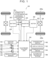
- FIG. 1 is a configuration diagram illustrating an overview of a configuration of an electrified vehicle 20 equipped with an in-vehicle control device according to the first embodiment of the present disclosure.
- the electrified vehicle 20 includes a motor 22, an inverter 23, a battery 24, a charging/discharging circuit 38, a connector 39, and an electronic control unit 30.
- the motor 22 is configured as, for example, a synchronous motor generator.
- a rotor of the motor 22 is connected to a drive shaft 25 that is linked to drive wheels 28a and 28b via a differential gear 26.
- the motor 22 is driven by direct current electric power from the battery 24 being converted into three-phase alternating current electric power by the inverter 23, and applying the three-phase alternating power by the inverter 23.
- the battery 24 is configured as a known lithium-ion secondary battery or nickel-metal hydride secondary battery.
- the charging/discharging circuit 38 has one end thereof connected to an electric power line connected to the battery 24, and the other end thereof connected to the connector 39 that is connected to an external power source.
- the charging/discharging circuit 38 has a charging/discharging relay that is omitted from illustration, and can connect to and disconnect from the battery 24 using the charging/discharging relay.
- the electronic control unit 30 is configured as a microcomputer, which is made up primarily of a central processing unit (CPU) that is omitted from illustration. Signals from various types of sensors are input to the electronic control unit 30 via an input port. For example, the electronic control unit 30 inputs an ignition signal from an ignition switch 42, a shift position SP from a shift position sensor 44 for detecting a position of a shift lever 43, an accelerator operation amount Acc from an accelerator pedal position sensor 46 for detecting depression amount of an accelerator pedal 45, a brake pedal position BP from a brake pedal position sensor 48 for detecting depression amount of a brake pedal 47, a vehicle speed V from a vehicle speed sensor 49, and so forth.
- an ignition signal from an ignition switch 42
- a shift position SP from a shift position sensor 44 for detecting a position of a shift lever 43
- an accelerator operation amount Acc from an accelerator pedal position sensor 46 for detecting depression amount of an accelerator pedal 45
- a brake pedal position BP from a brake pedal position sensor 48 for detecting depression amount of
- the electronic control unit 30 also inputs a rotational position ⁇ from a rotational position sensor (omitted from illustration) that detects a rotational position of the motor 22, battery voltage Vb from a voltage sensor (omitted from illustration) that is attached to an output terminal of the battery 24, battery current Ib from a current sensor (omitted from illustration) that is attached to the output terminal of battery 24, charging/discharging voltage Vchg from a voltage sensor that is attached to the charging/discharging circuit 38, charging/discharging current Ichg from a current sensor that is attached to the charging/discharging circuit 38, and so forth. Further, the electronic control unit 30 also inputs a switch signal SW from a changeover switch 50 for switching various types of displays on the display device 52.
- the electronic control unit 30 outputs various types of control signals via an output port. For example, the electronic control unit 30 outputs a display control signal to the display device 52, a communication control signal to a communication device 54, and so forth.
- the electronic control unit 30 also outputs a switching control signal for switching a switching element (omitted from illustration) to the inverter 23 for driving the motor 22, a drive control signal to a system main relay (omitted from illustration) attached near the battery 24, and a drive control signal to the charging/discharging relay (omitted from illustration) attached to the charging/discharging circuit 38.
- the electronic control unit 30 communicates with an automotive navigation system 56 that displays various types of information, provides route guidance, and so forth.
- a signal line 40 is connected to the electronic control unit 30 for communicating with an external power source side when the external power source is connected to the connector 39.
- the electronic control unit 30 calculates revolutions Nm of the motor 22 based on the rotational position ⁇ from the rotational position sensor (omitted from illustration) that detects the rotational position of the motor 22, calculates a storage proportion SOC of the battery 24 based on the battery voltage Vb and the battery current Ib, and so forth.
- the storage proportion SOC is the proportion of the remaining charge as to the total capacity of the battery 24.
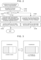
- FIG. 2 is a flowchart showing an example of charging-in-progress display processing that is executed by the electronic control unit 30 while charging. This charging-in-progress display processing is repeatedly executed at predetermined time intervals (e.g., every 30 seconds or 1 minute) while the battery 24 is being charged.
- the electronic control unit 30 first acquires the storage proportion SOC of the battery 24 (step S100).
- the storage proportion SOC is acquired by inputting values calculated based on the battery voltage Vb and the battery current Ib.
- determination is made regarding whether the storage proportion SOC of the battery 24 is lower than a predetermined storage proportion S1 that is lower than the full-charge proportion (100%) (step S110).
- a predetermined storage proportion S1 70%, 80%, 90%, or the like, for example, can be used.
- a first necessary charging time required until the storage proportion SOC of the battery 24 reaches the predetermined storage proportion S1 by performing charging using direct current electric power from the external direct current power source is acquired (step S120).
- a relation between charging voltage (battery voltage Vb) and the first necessary charging time is found in advance through experimentation or machine learning and stored as a map for setting the first necessary charging time, and when the charging voltage is provided, the first necessary charging time is acquired by deriving the corresponding first necessary charging time from the map.
- the first necessary charging time that is acquired is then output by display on the display device 52 (step S130).
- step S140 When the charging of the battery 24 by the external direct current power source progresses, and the storage proportion SOC of the battery 24 is no lower than the predetermined storage proportion S1, a negative determination is made in step S110, and a second necessary charging time required for the charging of the battery 24 by the external direct current power source to reach the full-charge proportion (100%) is acquired (step S140).
- the relation between the charging voltage (battery voltage Vb) and the second necessary charging time is found in advance through experimentation or machine learning and stored as a map for setting the second necessary charging time, and when the charging voltage is provided, the second necessary charging time is acquired by deriving the corresponding second necessary charging time from the map.
- the second necessary charging time that is acquired is then output by display on the display device 52 (step S150).
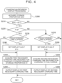
- FIG. 3 is an explanatory diagram illustrating an example of the way in which the display switches from display of the first necessary charging time on the display device 52 to display of the second necessary charging time on the display device 52.
- 80% is used as the predetermined storage proportion S1
- the storage proportion SOC of the battery 24 at that time is displayed as an image as well.
- the first necessary charging time (30 minutes) required for the storage proportion SOC of the battery 24 to reach the predetermined storage proportion S1 (80%) is displayed on the display device 52, as illustrated to the left side in FIG. 3 .
- the display of the first necessary charging time on the display device 52 is switched, and the second necessary charging time (1 hour 30 minutes) required for the storage proportion SOC of the battery 24 to reach the full-charge proportion (100%) is displayed on the display device 52.
- the electronic control unit 30 installed in the electrified vehicle 20 according to the first embodiment described above, while the battery 24 is being charged by the external direct current power source, when the storage proportion SOC of the battery 24 is lower than the predetermined storage proportion S1, the first necessary charging time required for the storage proportion SOC of the battery 24 to reach the predetermined storage proportion S1 is displayed on the display device 52, following which, when the storage proportion SOC of the battery 24 is no lower than the predetermined storage proportion S1, the display device 52 switches to displaying the second necessary charging time required for the storage proportion SOC of the battery 24 to reach the full-charge proportion (100%).
- the display on the display device 52 while charging can be simplified, and misreading by the user can be suppressed.
- the necessary time required for charging can be displayed more appropriately while charging.
- the electronic control unit 30 executes the charging-in-progress display processing exemplified in FIG. 4 .
- the charging-in-progress display processing in FIG. 4 is also repeatedly executed at predetermined time intervals (e.g., every 30 seconds or 1 minute) while the battery 24 is being charged.
- the electronic control unit 30 acquires the storage proportion SOC of the battery 24 (step S200), and determination is made regarding whether the storage proportion SOC of the battery 24 that is acquired is lower than the predetermined storage proportion S 1 that is lower than the full-charge proportion (100%) (step S210).
- a value of a display flag F is checked (step S220).
- the display flag F is a flag for setting whether the first necessary charging time is to be displayed on the display device 52 or the second necessary charging time is to be displayed on the display device 52, and is set by this charging-in-progress display processing.
- the value of the display flag F is 0, the first necessary charging time is displayed on the display device 52, and when the value of the display flag F is 1, the second necessary charging time is displayed on the display device 52.
- step S220 When determination is made in step S220 that the value of the display flag F is 0, determination is made regarding whether a predetermined amount of time has elapsed since the display of the first necessary charging time on the display device 52 started (step S230), and when determining that the predetermined amount of time has elapsed, the value of the display flag F is set to 1 (step S240).
- the predetermined amount of time 3 seconds or 5 seconds, 10 seconds or the like, for example, can be used.
- the first necessary charging time required for the storage proportion SOC of the battery 24 to reach the predetermined storage proportion S1, by the battery 24 being charged by the external direct current power source, is acquired (step S250), and the first necessary charging time that is acquired is output by display on the display device 52 (step S260).
- the processing ends.
- step S220 When determination is made in step S220 that the value of the display flag F is 1, determination is made regarding whether a predetermined amount of time has elapsed since the display of the second necessary charging time on the display device 52 started (step S270), and when determining that the predetermined amount of time has elapsed, the value of the display flag F is set to 0 (step S280).
- the second necessary charging time required for the storage proportion SOC of the battery 24 to reach the full-charge proportion (100%) by charging the battery 24 by the external direct current power source is then acquired (step S290).
- the second necessary charging time that is acquired is output by display on the display device 52 (step S300).
- step S210 When determination is made in step S210 that the storage proportion SOC of the battery 24 is no lower than the predetermined storage proportion S1, the second necessary charging time required for the storage proportion SOC of the battery 24 to reach the full-charge proportion (100%) by charging the battery 24 by the external direct current power source is acquired (step S290). The second necessary charging time that is acquired is output by display on the display device 52 (step S300). Thus, the processing ends.
- step S235 and S275 determination of whether the changeover switch 50 has been operated. That is to say, when determination is made in step S220 that the value of the display flag F is 0, whether the changeover switch 50 has been operated is determined (step S235), and when determining that the changeover switch 50 has been operated, the value of the display flag F is set to 1 (step S240), the first necessary charging time required for the storage proportion SOC of the battery 24 to reach the predetermined storage proportion S1 by charging the battery 24 by the external direct current power source is acquired (step S250), and the first necessary charging time that is acquired is output by display on the display device 52 (step S260).
- step S220 determines whether the changeover switch 50 has been operated (step S275), and when determining that the changeover switch 50 has been operated, the value of the display flag F is set to 0 (step S280), the second necessary charging time required for the storage proportion SOC of the battery 24 to reach the full-charge proportion (100%) by charging the battery 24 by the external direct current power source is acquired (step S290). The second necessary charging time that is acquired is output by display on the display device 52 (step S300).
- the processing ends. In this case as well, the display on the display device 52 while charging can be simplified, and misreading by the user can be suppressed.
- the first necessary charging time and the second necessary charging time are displayed on the display device 52 that is installed in the vehicle.
- display may be made on a display unit of a mobile terminal, such as a smartphone, a tablet, or the like.
- the electronic control unit 30 transmits the first necessary charging time or the second necessary charging time to a mobile terminal of the user via the communication device 54, the first necessary charging time or the second necessary charging time is received by the mobile terminal of the user in which application software for displaying is installed, and the display exemplified in FIG. 3 is displayed on a display unit of the mobile terminal.
- processing is performed in which the first necessary charging time and the second necessary charging time are displayed on the display device 52 while the connector 39 is connected to the external direct current power source and the battery 24 is being charged by direct current electric power supplied from the external direct current power source.
- processing may be performed in which the first necessary charging time and the second necessary charging time are displayed on the display device 52 while the connector 39 is connected to an external alternating current power source and the battery 24 is being charged by alternating current electric power supplied from the external alternating current power source.
- the battery 24 is an example of "power storage device”
- the electronic control unit 30 is an example of "in-vehicle control device”
- the display device 52 is an example of "display device.”
- the present disclosure is applicable to the manufacturing industry of in-vehicle control devices or the like.
Landscapes
- Engineering & Computer Science (AREA)
- Mechanical Engineering (AREA)
- Transportation (AREA)
- Power Engineering (AREA)
- Automation & Control Theory (AREA)
- Combustion & Propulsion (AREA)
- Chemical & Material Sciences (AREA)
- Human Computer Interaction (AREA)
- Life Sciences & Earth Sciences (AREA)
- Sustainable Development (AREA)
- Sustainable Energy (AREA)
- Charge And Discharge Circuits For Batteries Or The Like (AREA)
- Electric Propulsion And Braking For Vehicles (AREA)
Abstract
An in-vehicle control device (30), configured to control charging of a power storage device (24) that is installed in a vehicle, includes a processor. The processor is configured to output a first necessary charging time to a display device (52) when a predetermined condition is satisfied while charging the power storage device (24). The first necessary charging time is an amount of time required for a storage proportion of the power storage device (24) to reach a predetermined storage proportion that is lower than a full-charge proportion. The processor is configured to output a second necessary charging time to the display device (52) when the predetermined condition is not satisfied while charging the power storage device (24). The second necessary charging time is an amount of time required for the storage proportion of the power storage device (24) to reach the full-charge proportion.
Description
- The present disclosure relates to an in-vehicle control device configured to control charging of a power storage device installed in the vehicle using electric power from an external power source.
- An in-vehicle control device is proposed in which, while a battery installed in a vehicle is being rapidly charged, necessary time that will be required to reach full charge, and necessary time that will be required to reach a predetermined charge state that is lower than full charge, are displayed on a liquid crystal display panel installed in the vehicle (e.g., see
Japanese Unexamined Patent Application Publication No. 2012-025211 JP 2012-025211 A - However, in the above device, the necessary time that will be required to reach full charge and the necessary time that will be required to reach a predetermined charge state are displayed on the liquid crystal display panel, and accordingly displayed contents are not simple and may be misread by the user. Also, some users may desire to display just one of the necessary time that will be required to reach full charge and the necessary time that will be required to reach a predetermined charge state.
- The present disclosure provides an in vehicle control device that more appropriately displays necessary time required for charging while a power storage device installed in the vehicle is being charged by electric power from an external power source.
- An in-vehicle control device according to a first aspect of the present disclosure is configured to control charging of a power storage device that is installed in a vehicle, using electric power from an external power source. The in-vehicle control device includes a processor. The processor is configured to output a first necessary charging time to a display device when a predetermined condition is satisfied while charging the power storage device using the electric power from the external power source. The first necessary charging time is an amount of time required for a storage proportion of the power storage device to reach a predetermined storage proportion that is lower than a full-charge proportion. The processor is configured to output a second necessary charging time to the display device when the predetermined condition is not satisfied while charging the power storage device using the electric power from the external power source. The second necessary charging time is an amount of time required for the storage proportion of the power storage device to reach the full-charge proportion.
- In the in-vehicle control device according to the first aspect of the present disclosure, the predetermined condition may be a first condition in which the storage proportion of the power storage device is lower than the predetermined storage proportion.
- In the in-vehicle control device according to the first aspect of the present disclosure, the predetermined condition may be a second condition in which the storage proportion of the power storage device is lower than the predetermined storage proportion and also charging is performed using direct current electric power from an external direct current power source.
- In the in-vehicle control device according to the first aspect of the present disclosure, the display device may be a mobile terminal of a user.
- In the in-vehicle control device according to the first aspect of the present disclosure, the predetermined storage proportion may be a proportion within a range of 70% to 90% as to the full-charge proportion.
- In the in-vehicle control device according to the first aspect of the present disclosure, while charging the power storage device using electric power from the external power source, the first necessary charging time required for the storage proportion of the power storage device to reach the predetermined storage proportion that is lower than the full-charge proportion is output to the display device when the predetermined condition is satisfied, and the second necessary charging time required for the storage proportion of the power storage device to reach the full-charge proportion is output to the display device when the predetermined condition is not satisfied. According to the above configuration, the display on the display device while charging can be simplified, and misreading by the user can be suppressed. As a result, the necessary time required for charging can be displayed more appropriately while charging. Here, the predetermined condition may be a condition in which the storage proportion of the power storage device is lower than the predetermined storage proportion, or a condition in which charging is performed using direct current electric power from the external direct current power source in addition to this condition. Thus, when the storage proportion of the power storage device is lower than the predetermined storage proportion, the first necessary charging time required for the storage proportion of the power storage device to reach the predetermined storage proportion is displayed on the display device, and when the storage proportion of the power storage device becomes greater than the predetermined storage proportion, the second necessary charging time required for the storage proportion of the power storage device to reach the full-charge proportion is displayed on the display device. Examples of the display device include a liquid crystal display device built into an instrument panel of the vehicle, a display device built into an automotive navigation system, and a mobile terminal (smartphone, tablet, or the like) of the user. Note that, for the predetermined storage proportion, a proportion within the range of 70% to 90% of the full-charge proportion, for example, may be used.
- An in-vehicle control device according to a second aspect of the present disclosure is configured to control charging of a power storage device that is installed in a vehicle, using electric power from an external power source. The in-vehicle control device includes a processor configured to switch between output of a first necessary charging time to a display device and output of a second necessary charging time to the display device, at each predetermined time interval or each operation performed by a user, when a predetermined condition is satisfied while charging the power storage device using the electric power from the external power source. The first necessary charging time is an amount of time required for a storage proportion of the power storage device to reach a predetermined storage proportion that is lower than a full-charge proportion. The second necessary charging time is an amount of time required for the storage proportion of the power storage device to reach the full-charge proportion.
- In the in-vehicle control device according to the second aspect of the present disclosure, the predetermined condition may be a first condition in which the storage proportion of the power storage device is lower than the predetermined storage proportion.
- In the in-vehicle control device according to the second aspect of the present disclosure, the predetermined condition may be a second condition in which the storage proportion of the power storage device is lower than the predetermined storage proportion and also charging is performed using direct current electric power from an external direct current power source.
- In the in-vehicle control device according to the second aspect of the present disclosure, the display device may be a mobile terminal of the user.
- In the in-vehicle control device according to the second aspect of the present disclosure, the predetermined storage proportion may be a proportion within a range of 70% to 90% as to the full-charge proportion.
- In the in-vehicle control device according to the second aspect of the present disclosure, when the predetermined condition is satisfied while the power storage device is being charged using electric power from the external power source, output of the first necessary charging time required for the storage proportion of the power storage device to reach the predetermined storage proportion that is lower than the full-charge proportion to the display device, and output of the second necessary charging time required for the storage proportion of the power storage device to reach the full-charge proportion to the display device, are switched at each predetermined time interval or each operation performed by the user. By switching the first necessary charging time and the second necessary charging time at predetermined time intervals, the necessary time required for charging can be displayed more appropriately while charging. Here, the predetermined condition may be a condition in which the storage proportion of the power storage device is lower than the predetermined storage proportion, or a condition in which charging is performed using direct current electric power from the external direct current power source in addition to this condition. In this way, when the power storage proportion of the power storage device is lower than the predetermined power storage proportion, the first necessary charging time and the second necessary charging time are switched and displayed on the display device, and when the power storage proportion of the power storage device becomes higher than the predetermined power storage proportion, the second necessary charging time is displayed on the display device. Examples of the display device include a liquid crystal display device built into an instrument panel of the vehicle, a display device built into an automotive navigation system, and a mobile terminal (smartphone, tablet, or the like) of the user. Note that, for the predetermined storage proportion, a proportion within the range of 70% to 90% of the full-charge proportion, for example, may be used.
- Features, advantages, and technical and industrial significance of exemplary embodiments of the invention will be described below with reference to the accompanying drawings, in which like signs denote like elements, and wherein:
-
FIG. 1 is a configuration diagram illustrating an overview of a configuration of an electrified vehicle equipped with an in-vehicle control device according to an embodiment of the present disclosure; -
FIG. 2 is a flowchart showing an example of charging-in-progress display processing that is executed by an electronic control unit; -
FIG. 3 is an explanatory diagram illustrating an example of the way in which a display on a display device switches from a display of a first necessary charging time to a display of a second necessary charging time; -
FIG. 4 is a flowchart showing an example of charging-in-progress display processing according to a modification; and -
FIG. 5 is a flowchart showing an example of charging-in-progress display processing according to a modification. - A first embodiment of the present disclosure will be described.
FIG. 1 is a configuration diagram illustrating an overview of a configuration of an electrifiedvehicle 20 equipped with an in-vehicle control device according to the first embodiment of the present disclosure. Theelectrified vehicle 20 includes amotor 22, aninverter 23, abattery 24, a charging/discharging circuit 38, aconnector 39, and anelectronic control unit 30. - The
motor 22 is configured as, for example, a synchronous motor generator. A rotor of themotor 22 is connected to adrive shaft 25 that is linked todrive wheels differential gear 26. Themotor 22 is driven by direct current electric power from thebattery 24 being converted into three-phase alternating current electric power by theinverter 23, and applying the three-phase alternating power by theinverter 23. Note that thebattery 24 is configured as a known lithium-ion secondary battery or nickel-metal hydride secondary battery. - The charging/
discharging circuit 38 has one end thereof connected to an electric power line connected to thebattery 24, and the other end thereof connected to theconnector 39 that is connected to an external power source. The charging/dischargingcircuit 38 has a charging/discharging relay that is omitted from illustration, and can connect to and disconnect from thebattery 24 using the charging/discharging relay. - The
electronic control unit 30 is configured as a microcomputer, which is made up primarily of a central processing unit (CPU) that is omitted from illustration. Signals from various types of sensors are input to theelectronic control unit 30 via an input port. For example, theelectronic control unit 30 inputs an ignition signal from anignition switch 42, a shift position SP from ashift position sensor 44 for detecting a position of ashift lever 43, an accelerator operation amount Acc from an accelerator pedal position sensor 46 for detecting depression amount of an accelerator pedal 45, a brake pedal position BP from a brakepedal position sensor 48 for detecting depression amount of a brake pedal 47, a vehicle speed V from avehicle speed sensor 49, and so forth. Theelectronic control unit 30 also inputs a rotational position θ from a rotational position sensor (omitted from illustration) that detects a rotational position of themotor 22, battery voltage Vb from a voltage sensor (omitted from illustration) that is attached to an output terminal of thebattery 24, battery current Ib from a current sensor (omitted from illustration) that is attached to the output terminal ofbattery 24, charging/discharging voltage Vchg from a voltage sensor that is attached to the charging/discharging circuit 38, charging/discharging current Ichg from a current sensor that is attached to the charging/dischargingcircuit 38, and so forth. Further, theelectronic control unit 30 also inputs a switch signal SW from achangeover switch 50 for switching various types of displays on thedisplay device 52. - The
electronic control unit 30 outputs various types of control signals via an output port. For example, theelectronic control unit 30 outputs a display control signal to thedisplay device 52, a communication control signal to acommunication device 54, and so forth. Theelectronic control unit 30 also outputs a switching control signal for switching a switching element (omitted from illustration) to theinverter 23 for driving themotor 22, a drive control signal to a system main relay (omitted from illustration) attached near thebattery 24, and a drive control signal to the charging/discharging relay (omitted from illustration) attached to the charging/dischargingcircuit 38. Theelectronic control unit 30 communicates with anautomotive navigation system 56 that displays various types of information, provides route guidance, and so forth. Asignal line 40 is connected to theelectronic control unit 30 for communicating with an external power source side when the external power source is connected to theconnector 39. - The
electronic control unit 30 calculates revolutions Nm of themotor 22 based on the rotational position θ from the rotational position sensor (omitted from illustration) that detects the rotational position of themotor 22, calculates a storage proportion SOC of thebattery 24 based on the battery voltage Vb and the battery current Ib, and so forth. The storage proportion SOC is the proportion of the remaining charge as to the total capacity of thebattery 24. - Next, operations of the electrified
vehicle 20 according to the embodiment, particularly operations of displaying a charge state when thebattery 24 is being charged using electric power from an external power source, will be described. Note that in the embodiment, a description will be made regarding a display on thedisplay device 52 regarding charging while theconnector 39 is connected to an external direct current power source and thebattery 24 is being charged by direct current electric power supplied from the external direct current power source.FIG. 2 is a flowchart showing an example of charging-in-progress display processing that is executed by theelectronic control unit 30 while charging. This charging-in-progress display processing is repeatedly executed at predetermined time intervals (e.g., every 30 seconds or 1 minute) while thebattery 24 is being charged. - When the charging-in-progress display processing is executed, the
electronic control unit 30 first acquires the storage proportion SOC of the battery 24 (step S100). In the embodiment, the storage proportion SOC is acquired by inputting values calculated based on the battery voltage Vb and the battery current Ib. Next, determination is made regarding whether the storage proportion SOC of thebattery 24 is lower than a predetermined storage proportion S1 that is lower than the full-charge proportion (100%) (step S110). For the predetermined storage proportion S1, 70%, 80%, 90%, or the like, for example, can be used. - When determination is made in step S110 that the storage proportion SOC of the
battery 24 is lower than the predetermined storage proportion S1, a first necessary charging time required until the storage proportion SOC of thebattery 24 reaches the predetermined storage proportion S1 by performing charging using direct current electric power from the external direct current power source is acquired (step S120). In the first embodiment, a relation between charging voltage (battery voltage Vb) and the first necessary charging time is found in advance through experimentation or machine learning and stored as a map for setting the first necessary charging time, and when the charging voltage is provided, the first necessary charging time is acquired by deriving the corresponding first necessary charging time from the map. The first necessary charging time that is acquired is then output by display on the display device 52 (step S130). Thus, the processing ends. - When the charging of the
battery 24 by the external direct current power source progresses, and the storage proportion SOC of thebattery 24 is no lower than the predetermined storage proportion S1, a negative determination is made in step S110, and a second necessary charging time required for the charging of thebattery 24 by the external direct current power source to reach the full-charge proportion (100%) is acquired (step S140). In the first embodiment, the relation between the charging voltage (battery voltage Vb) and the second necessary charging time is found in advance through experimentation or machine learning and stored as a map for setting the second necessary charging time, and when the charging voltage is provided, the second necessary charging time is acquired by deriving the corresponding second necessary charging time from the map. The second necessary charging time that is acquired is then output by display on the display device 52 (step S150). Thus, the processing ends. -
FIG. 3 is an explanatory diagram illustrating an example of the way in which the display switches from display of the first necessary charging time on thedisplay device 52 to display of the second necessary charging time on thedisplay device 52. InFIG. 3 , 80% is used as the predetermined storage proportion S1, and the storage proportion SOC of thebattery 24 at that time is displayed as an image as well. In the charging-in-progress display processing, when the storage proportion SOC of thebattery 24 is lower than the predetermined storage proportion S1, the first necessary charging time (30 minutes) required for the storage proportion SOC of thebattery 24 to reach the predetermined storage proportion S1 (80%) is displayed on thedisplay device 52, as illustrated to the left side inFIG. 3 . When the storage proportion SOC of thebattery 24 is no longer lower than the predetermined storage proportion S1 (80%), the display of the first necessary charging time on thedisplay device 52 is switched, and the second necessary charging time (1hour 30 minutes) required for the storage proportion SOC of thebattery 24 to reach the full-charge proportion (100%) is displayed on thedisplay device 52. - In the
electronic control unit 30 installed in the electrifiedvehicle 20 according to the first embodiment described above, while thebattery 24 is being charged by the external direct current power source, when the storage proportion SOC of thebattery 24 is lower than the predetermined storage proportion S1, the first necessary charging time required for the storage proportion SOC of thebattery 24 to reach the predetermined storage proportion S1 is displayed on thedisplay device 52, following which, when the storage proportion SOC of thebattery 24 is no lower than the predetermined storage proportion S1, thedisplay device 52 switches to displaying the second necessary charging time required for the storage proportion SOC of thebattery 24 to reach the full-charge proportion (100%). Thus, the display on thedisplay device 52 while charging can be simplified, and misreading by the user can be suppressed. As a result, the necessary time required for charging can be displayed more appropriately while charging. - Next, a second embodiment of the present disclosure will be described. In the second embodiment, the same hardware configuration (configuration of the electrified vehicle 20) as in the first embodiment is used, and accordingly, description of the hardware configuration (configuration of the electrified vehicle 20) according to the second embodiment will be omitted. In the second embodiment, while the
battery 24 is being charged using an external direct current power source, theelectronic control unit 30 executes the charging-in-progress display processing exemplified inFIG. 4 . The charging-in-progress display processing inFIG. 4 is also repeatedly executed at predetermined time intervals (e.g., every 30 seconds or 1 minute) while thebattery 24 is being charged. - When the charging-in-progress display processing in
FIG. 4 is executed, theelectronic control unit 30 acquires the storage proportion SOC of the battery 24 (step S200), and determination is made regarding whether the storage proportion SOC of thebattery 24 that is acquired is lower than the predeterminedstorage proportion S 1 that is lower than the full-charge proportion (100%) (step S210). - When determination is made in step S210 that the storage proportion SOC of the
battery 24 is lower than the predetermined storage proportion S1, a value of a display flag F is checked (step S220). The display flag F is a flag for setting whether the first necessary charging time is to be displayed on thedisplay device 52 or the second necessary charging time is to be displayed on thedisplay device 52, and is set by this charging-in-progress display processing. In the second embodiment, when the value of the display flag F is 0, the first necessary charging time is displayed on thedisplay device 52, and when the value of the display flag F is 1, the second necessary charging time is displayed on thedisplay device 52. When determination is made in step S220 that the value of the display flag F is 0, determination is made regarding whether a predetermined amount of time has elapsed since the display of the first necessary charging time on thedisplay device 52 started (step S230), and when determining that the predetermined amount of time has elapsed, the value of the display flag F is set to 1 (step S240). For the predetermined amount of time, 3 seconds or 5 seconds, 10 seconds or the like, for example, can be used. The first necessary charging time required for the storage proportion SOC of thebattery 24 to reach the predetermined storage proportion S1, by thebattery 24 being charged by the external direct current power source, is acquired (step S250), and the first necessary charging time that is acquired is output by display on the display device 52 (step S260). Thus, the processing ends. - When determination is made in step S220 that the value of the display flag F is 1, determination is made regarding whether a predetermined amount of time has elapsed since the display of the second necessary charging time on the
display device 52 started (step S270), and when determining that the predetermined amount of time has elapsed, the value of the display flag F is set to 0 (step S280). The second necessary charging time required for the storage proportion SOC of thebattery 24 to reach the full-charge proportion (100%) by charging thebattery 24 by the external direct current power source is then acquired (step S290). The second necessary charging time that is acquired is output by display on the display device 52 (step S300). Thus, the processing ends. - When determination is made in step S210 that the storage proportion SOC of the
battery 24 is no lower than the predetermined storage proportion S1, the second necessary charging time required for the storage proportion SOC of thebattery 24 to reach the full-charge proportion (100%) by charging thebattery 24 by the external direct current power source is acquired (step S290). The second necessary charging time that is acquired is output by display on the display device 52 (step S300). Thus, the processing ends. - In the second embodiment described above, while the
battery 24 is being charged by the external direct current power source, when the storage proportion SOC of thebattery 24 is lower than the predetermined storage proportion S1, switching between the first necessary charging time being displayed on the display device 52 (e.g., the left side inFIG. 3 ) and the second necessary charging time being displayed on the display device 52 (e.g., the right side inFIG. 3 ) is performed at predetermined time intervals, and when the storage proportion SOC of thebattery 24 is no lower than the predetermined storage proportion S1, the second necessary charging time required for the storage proportion SOC of thebattery 24 to reach the full-charge proportion (100%) is displayed on thedisplay device 52. Thus, the display on thedisplay device 52 while charging can be simplified, and misreading by the user can be suppressed. As a result, the necessary time required for charging can be displayed more appropriately while charging. - In the second embodiment, while the
battery 24 is being charged by the external direct current power source, when the storage proportion SOC of thebattery 24 is lower than the predetermined storage proportion S1, switching between the first necessary charging time being displayed on thedisplay device 52 and the second necessary charging time being displayed on thedisplay device 52 is performed at predetermined time intervals. However, an arrangement may be made in which, when thechangeover switch 50 is operated by the user, the display of the first necessary charging time on thedisplay device 52 and the display of the second necessary charging time on thedisplay device 52 are switched. An example of charging-in-progress display processing in this case is shown inFIG. 5 . In the charging-in-progress display processing ofFIG. 5 , instead of determining whether a predetermined period of time has elapsed since switching the display in step S230 and step S270 ofFIG. 4 , determination of whether thechangeover switch 50 has been operated (steps S235 and S275) is performed. That is to say, when determination is made in step S220 that the value of the display flag F is 0, whether thechangeover switch 50 has been operated is determined (step S235), and when determining that thechangeover switch 50 has been operated, the value of the display flag F is set to 1 (step S240), the first necessary charging time required for the storage proportion SOC of thebattery 24 to reach the predetermined storage proportion S1 by charging thebattery 24 by the external direct current power source is acquired (step S250), and the first necessary charging time that is acquired is output by display on the display device 52 (step S260). Thus, the processing ends. When determination is made in step S220 that the value of the display flag F is 1, whether thechangeover switch 50 has been operated is determined (step S275), and when determining that thechangeover switch 50 has been operated, the value of the display flag F is set to 0 (step S280), the second necessary charging time required for the storage proportion SOC of thebattery 24 to reach the full-charge proportion (100%) by charging thebattery 24 by the external direct current power source is acquired (step S290). The second necessary charging time that is acquired is output by display on the display device 52 (step S300). Thus, the processing ends. In this case as well, the display on thedisplay device 52 while charging can be simplified, and misreading by the user can be suppressed. - In the first embodiment and the second embodiment, the first necessary charging time and the second necessary charging time are displayed on the
display device 52 that is installed in the vehicle. However, display may be made on a display unit of a mobile terminal, such as a smartphone, a tablet, or the like. In this case, an arrangement can be made in which theelectronic control unit 30 transmits the first necessary charging time or the second necessary charging time to a mobile terminal of the user via thecommunication device 54, the first necessary charging time or the second necessary charging time is received by the mobile terminal of the user in which application software for displaying is installed, and the display exemplified inFIG. 3 is displayed on a display unit of the mobile terminal. - In the first embodiment and the second embodiment, processing is performed in which the first necessary charging time and the second necessary charging time are displayed on the
display device 52 while theconnector 39 is connected to the external direct current power source and thebattery 24 is being charged by direct current electric power supplied from the external direct current power source. However, processing may be performed in which the first necessary charging time and the second necessary charging time are displayed on thedisplay device 52 while theconnector 39 is connected to an external alternating current power source and thebattery 24 is being charged by alternating current electric power supplied from the external alternating current power source. - Description will be given regarding correspondences between principal elements in the embodiments and principal elements of the invention described in the "SUMMARY OF THE INVENTION" section. In the embodiments, the
battery 24 is an example of "power storage device", theelectronic control unit 30 is an example of "in-vehicle control device", and thedisplay device 52 is an example of "display device." - It should be noted that the correspondences between the principal elements in the embodiments and the principal elements of the invention described in the "SUMMARY OF THE INVENTION" section are examples for describing in detail the modes for carrying out the invention described in the "SUMMARY OF THE INVENTION" section by the embodiments, and accordingly the correspondences are not intended to limit the elements of the invention described in the "SUMMARY OF THE INVENTION" section. That is to say, the invention described in the "SUMMARY OF THE INVENTION" section should be interpreted based on the description in that section, and the embodiments are only specific examples of the invention described in the "SUMMARY OF THE INVENTION" section.
- Although the present disclosure has been described above by way of embodiments, the present disclosure is not limited to such embodiments whatsoever, and may be carried out in various modes without departing from the spirit of the present disclosure, as a matter of course.
- The present disclosure is applicable to the manufacturing industry of in-vehicle control devices or the like.
Claims (6)
- An in-vehicle control device (30) configured to control charging of a power storage device (24) that is installed in a vehicle, using electric power from an external power source, the in-vehicle control device (30) comprising a processor configured tooutput a first necessary charging time to a display device (52) when a predetermined condition is satisfied while charging the power storage device (24) using the electric power from the external power source, the first necessary charging time is an amount of time required for a storage proportion of the power storage device (24) to reach a predetermined storage proportion that is lower than a full-charge proportion, andoutput a second necessary charging time to the display device (52) when the predetermined condition is not satisfied while charging the power storage device (24) using the electric power from the external power source, the second necessary charging time is an amount of time required for the storage proportion of the power storage device (24) to reach the full-charge proportion.
- An in-vehicle control device (30) configured to control charging of a power storage device (24) that is installed in a vehicle, using electric power from an external power source, the in-vehicle control device (30) comprising a processor configured to switch between output of a first necessary charging time to a display device (52) and output of a second necessary charging time to the display device (52), at each predetermined time interval or each operation performed by a user, when a predetermined condition is satisfied while charging the power storage device (24) using the electric power from the external power source, the first necessary charging time is an amount of time required for a storage proportion of the power storage device (24) to reach a predetermined storage proportion that is lower than a full-charge proportion, and the second necessary charging time is an amount of time required for the storage proportion of the power storage device (24) to reach the full-charge proportion.
- The in-vehicle control device (30) according to claim 1 or 2, wherein the predetermined condition is a first condition in which the storage proportion of the power storage device (24) is lower than the predetermined storage proportion.
- The in-vehicle control device (30) according to claim 3, wherein the predetermined condition is a second condition in which the storage proportion of the power storage device (24) is lower than the predetermined storage proportion and also charging is performed using direct current electric power from an external direct current power source.
- The in-vehicle control device (30) according to any of claims 1 to 4, wherein the display device (52) is a mobile terminal of a user.
- The in-vehicle control device (30) according to any of claims 1 to 5, wherein the predetermined storage proportion is a proportion within a range of 70% to 90% as to the full-charge proportion.
Applications Claiming Priority (1)
| Application Number | Priority Date | Filing Date | Title |
|---|---|---|---|
| JP2023093287A JP2024175477A (en) | 2023-06-06 | 2023-06-06 | Vehicle control device |
Publications (1)
| Publication Number | Publication Date |
|---|---|
| EP4474208A1 true EP4474208A1 (en) | 2024-12-11 |
Family
ID=90365240
Family Applications (1)
| Application Number | Title | Priority Date | Filing Date |
|---|---|---|---|
| EP24163188.6A Pending EP4474208A1 (en) | 2023-06-06 | 2024-03-13 | In-vehicle control device |
Country Status (4)
| Country | Link |
|---|---|
| US (1) | US12485916B2 (en) |
| EP (1) | EP4474208A1 (en) |
| JP (1) | JP2024175477A (en) |
| CN (1) | CN119093520A (en) |
Citations (9)
| Publication number | Priority date | Publication date | Assignee | Title |
|---|---|---|---|---|
| JPH11208313A (en) * | 1998-01-30 | 1999-08-03 | Mazda Motor Corp | Travel display device for hybrid electric vehicles |
| US7237203B1 (en) * | 1999-12-10 | 2007-06-26 | Bayerische Motoren Werke Aktiengesellschaft | Process and device for visual display of information in motor vehicles |
| US20100191404A1 (en) * | 2009-01-29 | 2010-07-29 | Kubota Corporation | Display System for Work Vehicle |
| JP2012025211A (en) | 2010-07-20 | 2012-02-09 | Nippon Seiki Co Ltd | Vehicular display device |
| WO2012117829A1 (en) * | 2011-03-03 | 2012-09-07 | 日本精機株式会社 | Display apparatus for vehicle |
| US20140330453A1 (en) * | 2012-02-22 | 2014-11-06 | Toyota Jidosha Kabushiki Kaisha | Vehicle remote control system, server, and remote control terminal |
| KR101936960B1 (en) * | 2012-12-27 | 2019-01-09 | 현대자동차주식회사 | Method and system for charging elecricity for vehicle |
| US20200171970A1 (en) * | 2018-12-03 | 2020-06-04 | Hyundai Motor Company | Eco-friendly vehicle and charging control method therefor |
| KR20210020645A (en) * | 2019-08-16 | 2021-02-24 | 엘지전자 주식회사 | Control system and method for charging the electric vehicle |
Family Cites Families (9)
| Publication number | Priority date | Publication date | Assignee | Title |
|---|---|---|---|---|
| JP4038860B2 (en) * | 1998-02-16 | 2008-01-30 | ソニー株式会社 | Charger |
| JP4352496B2 (en) * | 1999-03-12 | 2009-10-28 | ソニー株式会社 | Battery pack charger |
| JP4360036B2 (en) * | 2001-02-14 | 2009-11-11 | ソニー株式会社 | Power supply apparatus and method, program storage medium, and program |
| JP4735683B2 (en) * | 2008-08-22 | 2011-07-27 | ソニー株式会社 | Charging apparatus and charging method |
| CN102227332B (en) * | 2008-11-28 | 2014-04-02 | 丰田自动车株式会社 | Vehicular charging system |
| JP5602409B2 (en) * | 2009-10-20 | 2014-10-08 | トヨタ自動車株式会社 | Power storage status display system for vehicles |
| JP5570835B2 (en) | 2010-02-05 | 2014-08-13 | 三洋電機株式会社 | Charger |
| JP6183707B2 (en) | 2013-12-04 | 2017-08-23 | 三菱自動車工業株式会社 | Charging system and method for calculating estimated charging end time in charging system |
| US11840157B2 (en) * | 2021-07-19 | 2023-12-12 | Rivian Ip Holdings, Llc | Charge time estimation |
-
2023
- 2023-06-06 JP JP2023093287A patent/JP2024175477A/en active Pending
-
2024
- 2024-03-04 US US18/594,116 patent/US12485916B2/en active Active
- 2024-03-13 EP EP24163188.6A patent/EP4474208A1/en active Pending
- 2024-03-19 CN CN202410309418.4A patent/CN119093520A/en active Pending
Patent Citations (9)
| Publication number | Priority date | Publication date | Assignee | Title |
|---|---|---|---|---|
| JPH11208313A (en) * | 1998-01-30 | 1999-08-03 | Mazda Motor Corp | Travel display device for hybrid electric vehicles |
| US7237203B1 (en) * | 1999-12-10 | 2007-06-26 | Bayerische Motoren Werke Aktiengesellschaft | Process and device for visual display of information in motor vehicles |
| US20100191404A1 (en) * | 2009-01-29 | 2010-07-29 | Kubota Corporation | Display System for Work Vehicle |
| JP2012025211A (en) | 2010-07-20 | 2012-02-09 | Nippon Seiki Co Ltd | Vehicular display device |
| WO2012117829A1 (en) * | 2011-03-03 | 2012-09-07 | 日本精機株式会社 | Display apparatus for vehicle |
| US20140330453A1 (en) * | 2012-02-22 | 2014-11-06 | Toyota Jidosha Kabushiki Kaisha | Vehicle remote control system, server, and remote control terminal |
| KR101936960B1 (en) * | 2012-12-27 | 2019-01-09 | 현대자동차주식회사 | Method and system for charging elecricity for vehicle |
| US20200171970A1 (en) * | 2018-12-03 | 2020-06-04 | Hyundai Motor Company | Eco-friendly vehicle and charging control method therefor |
| KR20210020645A (en) * | 2019-08-16 | 2021-02-24 | 엘지전자 주식회사 | Control system and method for charging the electric vehicle |
Also Published As
| Publication number | Publication date |
|---|---|
| US20240409110A1 (en) | 2024-12-12 |
| JP2024175477A (en) | 2024-12-18 |
| US12485916B2 (en) | 2025-12-02 |
| CN119093520A (en) | 2024-12-06 |
Similar Documents
| Publication | Publication Date | Title |
|---|---|---|
| EP2101183B1 (en) | Control device for power storage device mounted on a vehicle | |
| CN110254279B (en) | Vehicle control device and automobile | |
| US20200134944A1 (en) | Electric vehicle and control method for electric vehicle | |
| EP3100924B1 (en) | Method and apparatus for controlling plug-in hybrid electric vehicle, as well as computer-readable medium | |
| EP3785972B1 (en) | Display system and vehicle including the same, and method of display of status of secondary battery | |
| CN107399328B (en) | Display device | |
| EP3640077A1 (en) | Vehicle, deterioration evaluation device for secondary battery, and deterioration evaluation method for secondary battery | |
| JP6414111B2 (en) | Display device | |
| JPH11206028A (en) | Battery remaining capacity detection device | |
| CN112448058B (en) | Display system, vehicle, and method for displaying state of secondary battery | |
| EP4474208A1 (en) | In-vehicle control device | |
| JP2009286374A (en) | Travel display device | |
| EP3640072B1 (en) | Display device | |
| JP2000299939A (en) | In-vehicle battery control system | |
| CN116766997B (en) | Electric vehicle | |
| JP5848218B2 (en) | Range display device | |
| EP4578686A1 (en) | Hybrid electric vehicle, control method for hybrid electric vehicle, power supply mode setting system, and power supply mode setting method | |
| JP2020036501A (en) | Charging system | |
| JP2024158437A (en) | Charger Management System | |
| JP2021040370A (en) | Display device |
Legal Events
| Date | Code | Title | Description |
|---|---|---|---|
| PUAI | Public reference made under article 153(3) epc to a published international application that has entered the european phase |
Free format text: ORIGINAL CODE: 0009012 |
|
| STAA | Information on the status of an ep patent application or granted ep patent |
Free format text: STATUS: REQUEST FOR EXAMINATION WAS MADE |
|
| 17P | Request for examination filed |
Effective date: 20240313 |
|
| AK | Designated contracting states |
Kind code of ref document: A1 Designated state(s): AL AT BE BG CH CY CZ DE DK EE ES FI FR GB GR HR HU IE IS IT LI LT LU LV MC ME MK MT NL NO PL PT RO RS SE SI SK SM TR |