EP4474179A1 - Top port apparatus for air suspension - Google Patents
Top port apparatus for air suspension Download PDFInfo
- Publication number
- EP4474179A1 EP4474179A1 EP23177862.2A EP23177862A EP4474179A1 EP 4474179 A1 EP4474179 A1 EP 4474179A1 EP 23177862 A EP23177862 A EP 23177862A EP 4474179 A1 EP4474179 A1 EP 4474179A1
- Authority
- EP
- European Patent Office
- Prior art keywords
- extension part
- casing
- casing body
- air suspension
- port apparatus
- Prior art date
- Legal status (The legal status is an assumption and is not a legal conclusion. Google has not performed a legal analysis and makes no representation as to the accuracy of the status listed.)
- Granted
Links
Images






Classifications
-
- B—PERFORMING OPERATIONS; TRANSPORTING
- B60—VEHICLES IN GENERAL
- B60G—VEHICLE SUSPENSION ARRANGEMENTS
- B60G11/00—Resilient suspensions characterised by arrangement, location or kind of springs
- B60G11/26—Resilient suspensions characterised by arrangement, location or kind of springs having fluid springs only, e.g. hydropneumatic springs
- B60G11/28—Resilient suspensions characterised by arrangement, location or kind of springs having fluid springs only, e.g. hydropneumatic springs characterised by means specially adapted for attaching the spring to axle or sprung part of the vehicle
-
- B—PERFORMING OPERATIONS; TRANSPORTING
- B60—VEHICLES IN GENERAL
- B60G—VEHICLE SUSPENSION ARRANGEMENTS
- B60G17/00—Resilient suspensions having means for adjusting the spring or vibration-damper characteristics, for regulating the distance between a supporting surface and a sprung part of vehicle or for locking suspension during use to meet varying vehicular or surface conditions, e.g. due to speed or load
- B60G17/02—Spring characteristics, e.g. mechanical springs and mechanical adjusting means
- B60G17/04—Spring characteristics, e.g. mechanical springs and mechanical adjusting means fluid spring characteristics
- B60G17/0408—Spring characteristics, e.g. mechanical springs and mechanical adjusting means fluid spring characteristics details, e.g. antifreeze for suspension fluid, pumps, retarding means per se
-
- B—PERFORMING OPERATIONS; TRANSPORTING
- B60—VEHICLES IN GENERAL
- B60G—VEHICLE SUSPENSION ARRANGEMENTS
- B60G11/00—Resilient suspensions characterised by arrangement, location or kind of springs
- B60G11/26—Resilient suspensions characterised by arrangement, location or kind of springs having fluid springs only, e.g. hydropneumatic springs
- B60G11/30—Resilient suspensions characterised by arrangement, location or kind of springs having fluid springs only, e.g. hydropneumatic springs having pressure fluid accumulator therefor, e.g. accumulator arranged in vehicle frame
-
- B—PERFORMING OPERATIONS; TRANSPORTING
- B60—VEHICLES IN GENERAL
- B60G—VEHICLE SUSPENSION ARRANGEMENTS
- B60G13/00—Resilient suspensions characterised by arrangement, location or type of vibration dampers
- B60G13/02—Resilient suspensions characterised by arrangement, location or type of vibration dampers having dampers dissipating energy, e.g. frictionally
- B60G13/06—Resilient suspensions characterised by arrangement, location or type of vibration dampers having dampers dissipating energy, e.g. frictionally of fluid type
- B60G13/10—Resilient suspensions characterised by arrangement, location or type of vibration dampers having dampers dissipating energy, e.g. frictionally of fluid type pneumatic
-
- B—PERFORMING OPERATIONS; TRANSPORTING
- B60—VEHICLES IN GENERAL
- B60G—VEHICLE SUSPENSION ARRANGEMENTS
- B60G17/00—Resilient suspensions having means for adjusting the spring or vibration-damper characteristics, for regulating the distance between a supporting surface and a sprung part of vehicle or for locking suspension during use to meet varying vehicular or surface conditions, e.g. due to speed or load
- B60G17/02—Spring characteristics, e.g. mechanical springs and mechanical adjusting means
- B60G17/04—Spring characteristics, e.g. mechanical springs and mechanical adjusting means fluid spring characteristics
- B60G17/052—Pneumatic spring characteristics
-
- F—MECHANICAL ENGINEERING; LIGHTING; HEATING; WEAPONS; BLASTING
- F16—ENGINEERING ELEMENTS AND UNITS; GENERAL MEASURES FOR PRODUCING AND MAINTAINING EFFECTIVE FUNCTIONING OF MACHINES OR INSTALLATIONS; THERMAL INSULATION IN GENERAL
- F16F—SPRINGS; SHOCK-ABSORBERS; MEANS FOR DAMPING VIBRATION
- F16F9/00—Springs, vibration-dampers, shock-absorbers, or similarly-constructed movement-dampers using a fluid or the equivalent as damping medium
- F16F9/02—Springs, vibration-dampers, shock-absorbers, or similarly-constructed movement-dampers using a fluid or the equivalent as damping medium using gas only or vacuum
-
- F—MECHANICAL ENGINEERING; LIGHTING; HEATING; WEAPONS; BLASTING
- F16—ENGINEERING ELEMENTS AND UNITS; GENERAL MEASURES FOR PRODUCING AND MAINTAINING EFFECTIVE FUNCTIONING OF MACHINES OR INSTALLATIONS; THERMAL INSULATION IN GENERAL
- F16F—SPRINGS; SHOCK-ABSORBERS; MEANS FOR DAMPING VIBRATION
- F16F9/00—Springs, vibration-dampers, shock-absorbers, or similarly-constructed movement-dampers using a fluid or the equivalent as damping medium
- F16F9/32—Details
- F16F9/3207—Constructional features
- F16F9/3235—Constructional features of cylinders
- F16F9/3242—Constructional features of cylinders of cylinder ends, e.g. caps
-
- F—MECHANICAL ENGINEERING; LIGHTING; HEATING; WEAPONS; BLASTING
- F16—ENGINEERING ELEMENTS AND UNITS; GENERAL MEASURES FOR PRODUCING AND MAINTAINING EFFECTIVE FUNCTIONING OF MACHINES OR INSTALLATIONS; THERMAL INSULATION IN GENERAL
- F16F—SPRINGS; SHOCK-ABSORBERS; MEANS FOR DAMPING VIBRATION
- F16F9/00—Springs, vibration-dampers, shock-absorbers, or similarly-constructed movement-dampers using a fluid or the equivalent as damping medium
- F16F9/32—Details
- F16F9/3271—Assembly or repair
-
- F—MECHANICAL ENGINEERING; LIGHTING; HEATING; WEAPONS; BLASTING
- F16—ENGINEERING ELEMENTS AND UNITS; GENERAL MEASURES FOR PRODUCING AND MAINTAINING EFFECTIVE FUNCTIONING OF MACHINES OR INSTALLATIONS; THERMAL INSULATION IN GENERAL
- F16F—SPRINGS; SHOCK-ABSORBERS; MEANS FOR DAMPING VIBRATION
- F16F9/00—Springs, vibration-dampers, shock-absorbers, or similarly-constructed movement-dampers using a fluid or the equivalent as damping medium
- F16F9/32—Details
- F16F9/43—Filling or drainage arrangements, e.g. for supply of gas
-
- F—MECHANICAL ENGINEERING; LIGHTING; HEATING; WEAPONS; BLASTING
- F16—ENGINEERING ELEMENTS AND UNITS; GENERAL MEASURES FOR PRODUCING AND MAINTAINING EFFECTIVE FUNCTIONING OF MACHINES OR INSTALLATIONS; THERMAL INSULATION IN GENERAL
- F16J—PISTONS; CYLINDERS; SEALINGS
- F16J15/00—Sealings
- F16J15/02—Sealings between relatively-stationary surfaces
- F16J15/06—Sealings between relatively-stationary surfaces with solid packing compressed between sealing surfaces
- F16J15/062—Sealings between relatively-stationary surfaces with solid packing compressed between sealing surfaces characterised by the geometry of the seat
-
- B—PERFORMING OPERATIONS; TRANSPORTING
- B60—VEHICLES IN GENERAL
- B60G—VEHICLE SUSPENSION ARRANGEMENTS
- B60G15/00—Resilient suspensions characterised by arrangement, location or type of combined spring and vibration damper, e.g. telescopic type
- B60G15/08—Resilient suspensions characterised by arrangement, location or type of combined spring and vibration damper, e.g. telescopic type having fluid spring
- B60G15/12—Resilient suspensions characterised by arrangement, location or type of combined spring and vibration damper, e.g. telescopic type having fluid spring and fluid damper
-
- B—PERFORMING OPERATIONS; TRANSPORTING
- B60—VEHICLES IN GENERAL
- B60G—VEHICLE SUSPENSION ARRANGEMENTS
- B60G2202/00—Indexing codes relating to the type of spring, damper or actuator
- B60G2202/10—Type of spring
- B60G2202/15—Fluid spring
- B60G2202/154—Fluid spring with an accumulator
-
- B—PERFORMING OPERATIONS; TRANSPORTING
- B60—VEHICLES IN GENERAL
- B60G—VEHICLE SUSPENSION ARRANGEMENTS
- B60G2202/00—Indexing codes relating to the type of spring, damper or actuator
- B60G2202/30—Spring/Damper and/or actuator Units
- B60G2202/31—Spring/Damper and/or actuator Units with the spring arranged around the damper, e.g. MacPherson strut
- B60G2202/314—The spring being a pneumatic spring
-
- B—PERFORMING OPERATIONS; TRANSPORTING
- B60—VEHICLES IN GENERAL
- B60G—VEHICLE SUSPENSION ARRANGEMENTS
- B60G2204/00—Indexing codes related to suspensions per se or to auxiliary parts
- B60G2204/10—Mounting of suspension elements
- B60G2204/12—Mounting of springs or dampers
- B60G2204/126—Mounting of pneumatic springs
-
- B—PERFORMING OPERATIONS; TRANSPORTING
- B60—VEHICLES IN GENERAL
- B60G—VEHICLE SUSPENSION ARRANGEMENTS
- B60G2206/00—Indexing codes related to the manufacturing of suspensions: constructional features, the materials used, procedures or tools
- B60G2206/01—Constructional features of suspension elements, e.g. arms, dampers, springs
- B60G2206/40—Constructional features of dampers and/or springs
- B60G2206/42—Springs
- B60G2206/424—Plunger or top retainer construction for bellows or rolling lobe type air springs
-
- B—PERFORMING OPERATIONS; TRANSPORTING
- B60—VEHICLES IN GENERAL
- B60G—VEHICLE SUSPENSION ARRANGEMENTS
- B60G2206/00—Indexing codes related to the manufacturing of suspensions: constructional features, the materials used, procedures or tools
- B60G2206/01—Constructional features of suspension elements, e.g. arms, dampers, springs
- B60G2206/80—Manufacturing procedures
- B60G2206/82—Joining
- B60G2206/8208—Joining by hemming or seaming, e.g. by folding of the rim
-
- B—PERFORMING OPERATIONS; TRANSPORTING
- B60—VEHICLES IN GENERAL
- B60G—VEHICLE SUSPENSION ARRANGEMENTS
- B60G2206/00—Indexing codes related to the manufacturing of suspensions: constructional features, the materials used, procedures or tools
- B60G2206/01—Constructional features of suspension elements, e.g. arms, dampers, springs
- B60G2206/80—Manufacturing procedures
- B60G2206/82—Joining
- B60G2206/8209—Joining by deformation
- B60G2206/82092—Joining by deformation by press-fitting
-
- B—PERFORMING OPERATIONS; TRANSPORTING
- B60—VEHICLES IN GENERAL
- B60G—VEHICLE SUSPENSION ARRANGEMENTS
- B60G2500/00—Indexing codes relating to the regulated action or device
- B60G2500/20—Spring action or springs
- B60G2500/206—Variable pressure accumulators for hydropneumatic suspensions
- B60G2500/2064—Variable pressure accumulators for hydropneumatic suspensions by varying the number of accumulators connected in parallel to the hydraulic cylinder
-
- F—MECHANICAL ENGINEERING; LIGHTING; HEATING; WEAPONS; BLASTING
- F16—ENGINEERING ELEMENTS AND UNITS; GENERAL MEASURES FOR PRODUCING AND MAINTAINING EFFECTIVE FUNCTIONING OF MACHINES OR INSTALLATIONS; THERMAL INSULATION IN GENERAL
- F16F—SPRINGS; SHOCK-ABSORBERS; MEANS FOR DAMPING VIBRATION
- F16F9/00—Springs, vibration-dampers, shock-absorbers, or similarly-constructed movement-dampers using a fluid or the equivalent as damping medium
- F16F9/32—Details
- F16F9/54—Arrangements for attachment
Definitions
- Exemplary embodiments of the present disclosure relate to a top port apparatus for air suspension, and more particularly, to a top port apparatus for air suspension with improved airtightness and durability.
- suspension systems improve driving stability and ride comfort while a vehicle is traveling by performing functions such as absorbing vibration or shock transmitted from the road surface through an axle and balancing a vehicle body between the axle and the vehicle body.
- air suspension may adjust an air pressure in an air spring by supporting a vehicle body with an air spring using the elasticity of compressed air and thus adjust the pressure according to the number of passengers or the condition of the road surface, thereby keeping the spring smooth at all times. Therefore, the air suspension is more advantageous for ride comfort.
- the air suspension behaves nonlinearly in its characteristics, the pressure and volume of gas are inversely proportional at a certain temperature. Accordingly, the air suspension has a characteristic in that when a loading weight increases due to loading of people or cargo, the air is compressed to provide a higher repulsive force, whereas when the loading weight decreases, the repulsive force returns to its original force.
- Various embodiments are directed to a top port apparatus for air suspension with improved airtightness and durability.
- a top port apparatus for air suspension may include a top casing connected to a vehicle body, a bottom casing disposed to face the top casing and connected to an air spring, and a sealing section configured to seal a gap between the top casing and the bottom casing.
- the top casing may include a top casing body, and a first extension part protruding outward from the top casing body.
- the bottom casing may include a bottom casing body coupled to the top casing body, and a second extension part protruding outward from the bottom casing body and disposed to face the first extension part.
- the sealing section may include an elastic member disposed between the first extension part and the second extension part, and a cover part disposed to face the elastic member and surround the first extension part and the second extension part.
- the cover part may have both ends that are deformed by press working and pressed to respective outer surfaces of the first second extension part and the second extension part.
- the sealing section may further include a guide member that is provided between at least one of the first second extension part or the second extension part and the cover part, and guides deformation of the cover part.
- a top port apparatus for air suspension may include: a middle casing, a top casing coupled to an upper side of the middle casing and connected to a vehicle body, a bottom casing coupled to a lower side of the middle casing and connected to an air spring, and a sealing section configured to seal a gap among the middle casing, the top casing, and the bottom casing.
- the middle casing may include a middle casing body disposed between the top casing and the bottom casing and having a valve chamber, and a seating part protruding outward from the middle casing body and extending along a circumferential surface of the middle casing body.
- the top casing may include a top casing body having a first chamber connecting with the valve chamber, and a first extension part protruding outward from the top casing body and seated on an upper side of the seating part.
- the bottom casing may include a bottom casing body having a second chamber and a third chamber connecting with the valve chamber, and a second extension part protruding outward from the bottom casing body and seated on a lower side of the seating part.
- the first extension part and the second extension part may each have a stepped cross-section.
- the first extension part and the second extension part may have ends that are spaced apart from and face each other.
- the sealing section may include an elastic member disposed between the first second extension part and the second extension part, and a cover part disposed to face the elastic member and surround the first extension part and the second extension part.
- the cover part may have both ends that are deformed by press working and pressed to respective outer surfaces of the first second extension part and the second extension part.
- the sealing section may further include a guide member that is provided between at least one of the first second extension part or the second extension part and the cover part, and guides deformation of the cover part.
- the guide member may gradually decrease in cross-sectional area as it is directed to the cover part.
- the guide member may be formed to be elastically deformable.
- the top port apparatus for air suspension can simplify the assembly process and reduce costs to manufacture as the middle casing, the top casing, and the bottom casing are vertically stacked and coupled to each other.
- the top port apparatus for air suspension according to the present disclosure can double-block foreign substances from entering the middle casing, the top casing, and the bottom casing or air from leaking out of the middle casing, the top casing, and the bottom casing, by the stepped contact structure of the seating part and the first and second extension parts, and the sealing section.
- the top port apparatus for air suspension according to the present disclosure can enhance the coupling force among the middle casing, the top casing, and the bottom casing by the cover part, and maintain the close contact of the elastic member with the first extension part and the second extension part.
- the top port apparatus for air suspension can block direct exposure of the elastic member to the outside by the cover part, thereby enhancing overall sealing performance of the sealing suction and preventing damage to the elastic member.
- first, second, A, B, (a), (b) or the like may be used herein to describe components.
- Each of these terminologies is not used to define an essence, order or sequence of a corresponding component but used merely to distinguish the corresponding component from other component(s).
- a first component may be referred to as a second component, and similarly the second component may also be referred to as the first component.
- FIG. 1 is a perspective view schematically illustrating a configuration of a top port apparatus for air suspension according to a first embodiment of the present disclosure.
- FIG. 2 is a cross-sectional view schematically illustrating the configuration of the top port apparatus for air suspension according to the first embodiment of the present disclosure.
- the top port apparatus for air suspension is configured to connect a vehicle body to a piston rod A of a shock absorber coupled with an axle and to adjust an air pressure within an air spring B, and includes a top casing 10, a bottom casing 20, and a sealing section 30.
- the top casing 10 defines an upper appearance of the top port apparatus for air suspension and is connected to the vehicle body. That is, the top casing 10 functions to support the top port apparatus for air suspension as a whole with respect to the vehicle body.
- the top casing 10 may include a top casing body 11, a rod mount 12, and a first extension part 13.
- the top casing body 11 may have a cylindrical shape with an outer circumference forming a closed curve.
- the top casing body 11 may be made of a synthetic resin material and manufactured by injection molding.
- the top casing body 11 may have an upper surface detachably connected to the vehicle body by bolting or the like.
- the bottom of the top casing body 11 is coupled to the top of the bottom casing 20 to be described later.
- the bottom of the top casing body 11 may be integrally bonded to the top of the bottom casing body 20 with adhesive or the like.
- the top casing body 11 may have an upper chamber Ca, which is defined therein and filled with air.
- the upper chamber Ca may pass through the lower surface of the top casing body 11.
- the rod mount 12 is coupled to the top casing body 11 and supports the piston rod A. That is, the rod mount 12 functions to connect the piston rod A to the vehicle body via the top casing body 11.
- the rod mount 12 according to the present embodiment may have a cup shape with open upper and lower sides.
- the rod mount 12 may be made of a metal material such as aluminum.
- the rod mount 12 may be integrally coupled to the top casing body 11 by insert injection or the like.
- the rod mount 12 may have a bottom protruding into the top casing body 11.
- the top of the piston rod A may be inserted into the rod mount 12 through the bottom of the rod mount 12.
- the top of the piston rod A may be detachably fixed to the rod mount 12 by bolting or the like.
- the first extension part 13 protrudes outward from the top casing body 11.
- the first extension part 13 may protrude from the outer surface of the top casing body 11 in a direction perpendicular to the piston rod A.
- the first extension part 13 may be made of the same material as the top casing body 11.
- the first extension part 13 may continuously extend along the circumferential surface of the top casing body 11 to have a substantially ring shape.
- the first extension part 13 may have a stepped cross-section.
- the bottom casing 20 is disposed to face the top casing 10 and defines a lower appearance of the top port apparatus for air suspension.
- the bottom casing 20 is connected to the air spring B, and functions to allow air to be transferred between the top port apparatus for air suspension and the air spring B.
- the bottom casing 20 includes a bottom casing body 21 and a second extension part 22.
- the bottom casing body 21 may have a cylindrical shape with an outer circumference forming a closed curve.
- the bottom casing body 21 may be made of a synthetic resin material and manufactured by injection molding.
- the top of the bottom casing body 21 may be coupled to the bottom of the top casing body 11. In this case, the top of the bottom casing body 21 may be integrally bonded to the bottom of the top casing body 11 with adhesive or the like.
- the bottom of the bottom casing body 21 may be coupled to the top of the air spring B.
- the bottom casing body 310 may have therein a lower chamber Cb, which is filled with air and communicates with the upper chamber Ca, and a main chamber Cm, which is partitioned from the lower chamber Cb and communicates with the air spring B.
- the lower chamber Cb may communicate with the upper chamber Ca as the top casing body 11 is coupled to the bottom casing body 12.
- the upper chamber Ca or the lower chamber Cb may be supplied with air via a nozzle (not shown) or the like from the outside.
- a valve (not shown) may be further installed between the lower chamber Cb and the main chamber Cm to allow air to be transferred between the lower chamber Cb and the main chamber Cm.
- the second extension part 22 protrudes outward from the bottom casing body 21.
- the second extension part 22 may protrude from the outer surface of the bottom casing body 21 in a direction perpendicular to the piston rod A.
- the second extension part 22 may be made of the same material as the bottom casing body 21.
- the second extension part 22 may continuously extend along the circumferential surface of the bottom casing body 21 to have a substantially ring shape.
- the upper surface of the second extension part 22 is seated on the lower surface of the first extension part 13.
- the second extension part 22 may have a stepped cross-section corresponding to the cross-section of the first extension part 13.
- first and second extension parts 13 and 22 may form a structure in which they come into close contact with each other in a stepwise manner, thereby preventing foreign substances from entering or air from leaking between the top casing body 11 and the bottom casing body 21 together with the sealing section 30 to be described later.
- the sealing section 30 seals a gap between the top casing 10 and the bottom casing 20. That is, the sealing section 30 functions to prevent foreign substances from entering or air from leaking into the gap between the top casing 10 and the bottom casing 20.
- FIG. 3 is an enlarged view schematically illustrating the configuration of the sealing section according to the embodiment of the first embodiment of present disclosure.
- the sealing section 30 includes an elastic member 31 and a cover part 32.
- the elastic member 31 is disposed between the first extension part 13 and the second extension part 22.
- the elastic member 31 according to the present embodiment may have a substantially ring shape.
- the elastic member 31 may be disposed between the lower surface of the first extension part 13 and the upper surface of the second extension part 22.
- the elastic member 31 may be made of an elastically deformable material such as rubber or silicon.
- the elastic member 31 may have a height greater than the distance between the first extension part 13 and the second extension part 22. Accordingly, the respective upper and lower surfaces of the elastic member 31 may be tightly pressed against the lower surface of the end of the first extension part 13 and the upper surface of the end of the second extension part 22 by elastic deformation.
- the cover part 32 is disposed to face the elastic member 31 and surround the first extension part 13 and the second extension part 22. That is, the cover part 32 is coupled to the first extension part 13 and the second extension part 22 to enhance the coupling force between the top casing 10 and the bottom casing 20, and functions to maintain the close contact of the elastic member 31 with the first extension part 13 and the second extension part 22.
- the cover part 32 may block direct exposure of the elastic member 31 to the outside, thereby enhancing overall sealing performance of the sealing section 30 and preventing damage to the elastic member 31.
- the cover part 32 may have a hollow ring shape with open upper and lower sides.
- the inner surface of the cover part 32 may surround the circumferential surfaces of the ends of the first and second extension parts 13 and 22 and may be disposed to face the elastic member 31.
- the cover part 32 may be disposed to face the elastic member with the first or second extension part 13 or 22 interposed therebetween or to directly face the elastic member 31.
- the cover part 32 may have a vertical height greater than the length between the top of the first extension part 13 and the bottom of the second extension part 22. Accordingly, the cover part 32 may have both upper and lower ends that protrude upward from the first extension part 13 and downward from the second extension part 22, respectively, in a state in which the inner surface of the cover part 32 faces the circumferential surfaces of the ends of the first and second extension parts 13 and 22. In this state, the upper and lower ends of the cover part 32 may be deformed by press working and pressed and fixed to the outer surfaces of the first and second extension parts 13 and 22.
- the cover part 32 may be made of a metal material such as aluminum or steel so that it is variable in shape by press working while securing sufficient rigidity.
- the sealing section 30 may further include a guide member 33.
- the guide member 33 is provided between at least one of the first and second extension parts 13 and 22 and the cover part 32 and guides deformation of the cover part 32 by press working. More specifically, the guide member 33 supports the inner surface of the cover part 32 during press working of the cover part 32 to guide the end of the cover part 32 to be deformed into a predetermined shape, and at the same time functions to distribute the pressurized load applied to the end of the cover part 32. Accordingly, the guide member 33 can prevent the end of the cover part 32 from being deformed and broken at an excessive angle, and prevent the pressurized load applied to the end of the cover part 32 from being concentrated locally.
- the guide member 33 is provided between the second extension part 22 and the cover part 32 .
- the present disclosure is not limited thereto.
- the guide member 33 may be provided between the first extension part 13 and the cover part 32, or may consist of a plurality of guide members, which are provided between the first extension part 13 and the cover part 32 and between the second extension part 22 and the cover part 32, respectively.
- the guide member 33 may have a hollow ring shape with open upper and lower ends.
- the guide member 33 may be disposed such that its inner surface is in contact with the outer surface of the bottom casing body 21 and its upper surface is in contact with the lower surface of the second extension part 22.
- the guide member 33 may be fixed to the bottom casing body 21 or the second extension part 22 by welding, adhesive, or the like.
- the guide member 33 may be made of an elastically deformable material such as rubber, silicon, or synthetic resin.
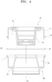
- FIGS. 4 to 7 are views schematically illustrating the process of assembling the top port apparatus for air suspension according to the first embodiment of the present disclosure.
- the top casing body 11 and the bottom casing body 21 may be disposed such that their respective lower and upper surfaces, which are opened by the respective upper chamber Ca and lower chamber Cb, face each other vertically.
- top casing body 11 and the bottom casing body 21 move in close proximity to each other, so the bottom of the top casing body 11 comes into contact with the top of the bottom casing body 21.
- the bottom of the top casing body 11 and the top of the bottom casing body 21 that are in contact with each other may be integrally coupled to each other with adhesive or the like.
- both upper and lower surfaces of the elastic member 31 may be tightly pressed and fixed to the lower surface of the first extension part 13 and the upper surface of the second extension part 22, respectively.
- the inner surface of the cover part 32 is disposed to face the circumferential surfaces of the ends of the first and second extension parts 13 and 22.
- the upper and lower ends of the cover part 32 are formed by press working, and pressed and fixed to the outer surfaces of the first and second extension parts 13 and 22.
- the upper end of the cover part 32 is deformed in a direction in which its inner surface is directed toward the outer surface of the first extension part 13 by the pressing force applied from a press tool (not shown) or the like, so that the upper end of the cover part 420 is pressed and fixed to the outer surface of the first extension part 13.
- the lower end of the cover part 32 is deformed in a direction in which its inner surface is directed toward the outer surface of the second extension part 22 by the pressing force applied from the press tool or the like.
- the inner surface of the cover part 32 may come into contact the outer surface of the guide member 33.
- the lower end of the cover part 32 may then be deformed into a shape corresponding to the shape of the guide member 33, and pressed and fixed to the outer surfaces of the guide member 33.
- FIG. 8 is a perspective view schematically illustrating a configuration of a top port apparatus for air suspension according to a second embodiment of the present disclosure.
- FIG. 9 is a cross-sectional view schematically illustrating the configuration of the top port apparatus for air suspension according to the second embodiment of the present disclosure.
- the top port apparatus for air suspension which is designated by reference numeral 1, according to the embodiment of the present disclosure is configured to connect a vehicle body to a piston rod A of a shock absorber coupled with an axle and to adjust an air pressure within an air spring B, and may include a middle casing 100, a top casing 200, a bottom casing 300, and sealing section 400.
- the middle casing 100 is disposed between the vehicle body and the air spring B, and interconnects the top casing 200 and the bottom casing 300.
- the middle casing 100 may include a middle casing body 110 and a seating part 120.
- the middle casing body 110 defines a schematic external appearance of the middle casing 100 and is disposed between the top casing 200 and the bottom casing 300.
- the middle casing body 110 according to the embodiment of the present disclosure may have a cylindrical shape with an outer circumference forming a closed curve.
- the cross-section of the middle casing body 110 perpendicular to the piston rod A may be asymmetrical.
- the middle casing body 110 may be made of a synthetic resin material and manufactured by injection molding.
- the middle casing body 110 may have therein a valve chamber V in which a solenoid valve (not shown) is installed to control the connection between a first chamber C1, a second chamber C2, and a third chamber C3, which will be described later, so that the stiffness of the air spring B is variable.
- the seating part 120 protrudes outward from the middle casing body 110 and supports a first extension part 230 and a second extension part 320 which will be described later.
- the seating part 120 may protrude from the outer surface of the middle casing body 110 in a direction perpendicular to the piston rod A.
- the seating part 120 may be made of the same material as the middle casing body 110.
- the seating part 120 may continuously extend along the circumferential surface of the middle casing body 110 to have a substantially ring shape.
- the seating part 120 may have a stepped cross-section in which its height gradually increases toward the end thereof.
- the top casing 200 is coupled to the top of the middle casing 100 and connected to the vehicle body. That is, the top casing 200 functions to support the top port apparatus for air suspension 1 according to the embodiment of the present disclosure as a whole with respect to the vehicle body.
- the top casing 200 may include a top casing body 210, a rod mount 220, and a first extension part 230.
- the top casing body 210 defines a schematic external appearance of the top casing 200 and is disposed above the middle casing body 110.
- the top casing body 210 according to the embodiment of the present disclosure may have a cylindrical shape with an outer circumference forming a closed curve.
- the cross-section of the top casing body 210 perpendicular to the piston rod A may be asymmetrical, more specifically, may have a shape corresponding to the cross-section of the middle casing body 110.
- the top casing body 210 may be made of a synthetic resin material and manufactured by injection molding.
- the top casing body 210 has an upper surface detachably connected to the vehicle body by bolting or the like.
- the bottom of the top casing body 210 is coupled to the top of the middle casing body 110.
- the bottom of the top casing body 210 may be integrally bonded to the top of the middle casing body 110 with adhesive or the like.
- the top casing body 210 may have therein a first chamber C1, which is filled with air and connects with the valve chamber V, and a fourth chamber C4, which is partitioned from the first chamber C1 and connects with the valve chamber V and a third chamber C3 to be described later.
- the rod mount 220 is coupled to the top casing body 210 and supports the piston rod A. That is, the rod mount 220 functions to connect the piston rod A to the vehicle body via the top casing body 210.
- the rod mount 220 according to the embodiment of the present disclosure may have a cup shape with open upper and lower sides.
- the rod mount 220 may be made of a metal material such as aluminum.
- the rod mount 220 may be integrally coupled to the top casing body 210 by insert injection or the like.
- the rod mount 220 has a bottom protruding into the top casing body 210.
- the top of the piston rod A is inserted into the rod mount 220 through the bottom of the rod mount 220.
- the top of the piston rod A may be detachably fixed to the rod mount 220 by bolting or the like.
- the first extension part 230 protrudes outward from the top casing body 210 and is seated on the upper side of the seating part 120.
- the first extension part 230 may protrude from the outer surface of the top casing body 210 in a direction perpendicular to the piston rod A.
- the first extension part 230 may be made of the same material as the top casing body 210.
- the first extension part 230 may continuously extend along the circumferential surface of the top casing body 210 to have a substantially ring shape.
- the lower surface of the first extension part 230 is seated on the upper surface of the seating part 120.
- the first extension part 230 may have a stepped cross-section in which its height gradually decreases toward the end thereof so as to correspond to the cross-section of the seating part 120. Accordingly, the first extension part 230 and the seating part 120 may form a structure in which they come into close contact with each other in a stepwise manner, thereby preventing foreign substances from entering or air from leaking between the middle casing body 110 and the top casing body 210 together with the sealing section 400.
- the bottom casing 300 is coupled to the bottom of the middle casing 100 and connected to the air spring B. That is, the bottom casing 300 functions to allow air to be transferred between the air spring B and the top port apparatus for air suspension 1 according to the embodiment of the present disclosure.
- the bottom casing 300 may include a bottom casing body 310 and a second extension part 320.
- the bottom casing body 310 defines a schematic external appearance of the bottom casing 300 and is disposed beneath the middle casing body 110.
- the bottom casing body 310 according to the embodiment of the present disclosure may have a cylindrical shape with an outer circumference forming a closed curve.
- the cross-section of the bottom casing body 310 perpendicular to the piston rod A may be asymmetrical, more specifically, may have a shape corresponding to the cross-section of the middle casing body 110.
- the bottom casing body 310 may be made of a synthetic resin material and manufactured by injection molding. The top of the bottom casing body 310 is coupled to the bottom of the middle casing body 110.
- the top of the bottom casing body 310 may be integrally bonded to the bottom of the middle casing body 110 with an adhesive or the like.
- the bottom of the bottom casing body 310 is coupled to the top of the air spring B.
- the bottom casing body 310 may have therein a second chamber C2, which is filled with air and connects with the valve chamber V, and a third chamber C3, which is partitioned from the second chamber C2 and connects with the fourth chamber C4 and the air spring B.
- the second extension part 320 protrudes outward from the bottom casing body 310 and is seated on the lower side of the seating part 120.
- the second extension part 320 may protrude from the outer surface of the bottom casing body 310 in a direction perpendicular to the piston rod A.
- the second extension part 320 may be made of the same material as the bottom casing body 310.
- the second extension part 320 may continuously extend along the circumferential surface of the bottom casing body 310 to have a substantially ring shape.
- the upper surface of the second extension part 320 is seated on the lower surface of the seating part 120.
- the second extension part 320 may have a stepped cross-section in which its height gradually decreases toward the end thereof so as to correspond to the cross-section of the seating part 120. Accordingly, the second extension part 320 and the seating part 120 may form a structure in which they come into close contact with each other in a stepwise manner, thereby preventing foreign substances from entering or air from leaking between the middle casing body 110 and the bottom casing body 310 together with the sealing section 400.
- the upper surface of the end of the second extension part 320 is spaced apart from and disposed to face the lower surface of the end of the first extension part 230. Accordingly, a space in which an elastic member 410 to be described later is installed may be provided between the ends of the first and second extension parts 230 and 320.
- the sealing section 400 seals a gap among the middle casing 100, the top casing 200, and the bottom casing 300. That is, the sealing section 400 functions to prevent foreign substances from entering or air from leaking into the gap among the middle casing 100, the top casing 200, and the bottom casing 300.
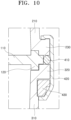
- FIG. 10 is an enlarged view schematically illustrating the configuration of the sealing section according to the second embodiment of the present disclosure.
- the sealing section 400 may include an elastic member 410, a cover part 420.
- the elastic member 410 is disposed between the ends of the first and second extension parts 230 and 320.
- the elastic member 410 according to the embodiment of the present disclosure may have a substantially ring shape.
- the elastic member 410 is disposed between the lower surface of the end of the first extension part 230 and the upper surface of the end of the second extension part 320.
- the elastic member 410 may be made of an elastically deformable material such as rubber or silicon.
- the elastic member 410 has a height greater than the distance between the first extension part 230 and the second extension part 320. Accordingly, the respective upper and lower surfaces of the elastic member 410 may be tightly pressed against the lower surface of the end of the first extension part 230 and the upper surface of the end of the second extension part 320 by elastic deformation.
- the cover part 420 is disposed to face the elastic member 410 and surround the first extension part 230 and the second extension part 320. That is, the cover part 420 is coupled to the first extension part 230 and the second extension part 320 to enhance the coupling force among the middle casing 100, the top casing 200, and the bottom casing 300, and functions to maintain the close contact of the elastic member 410 with the first extension part 230 and the second extension part 320.
- the cover part 420 may block direct exposure of the elastic member 410 to the outside, thereby enhancing overall sealing performance of the sealing section 400 and preventing damage to the elastic member 410.
- the cover part 420 according to the embodiment of the present disclosure may have a hollow ring shape with open upper and lower sides.
- the inner surface of the cover part 420 surrounds the circumferential surfaces of the ends of the first and second extension parts 230 and 320 and is disposed to face the elastic member 410.
- the cover part 420 has a vertical height greater than the length between the top of the first extension part 230 and the bottom of the second extension part 320. Accordingly, the cover part 420 may have both upper and lower ends that protrude upward from the first extension part 230 and downward from the second extension part 320, respectively, in a state in which the inner surface of the cover part 420 faces the circumferential surfaces of the ends of the first and second extension parts 230 and 320.
- the upper and lower ends of the cover part 420 may be deformed by press working and pressed and fixed to the outer surfaces of the first and second extension parts 230 and 320.
- the cover part 420 may be made of a metal material such as aluminum or steel so that it is variable in shape by press working while securing sufficient rigidity.
- the sealing section 400 according to the present embodiment may further include a guide member 430.
- the guide member 430 is provided between at least one of the first and second extension parts 230 and 320 and the cover part 420 and guides deformation of the cover part 420 by press working. More specifically, the guide member 430 supports the inner surface of the cover part 420 during press working of the cover part 420 to guide the end of the cover part 420 to be deformed into a predetermined shape, and at the same time functions to distribute the pressurized load applied to the end of the cover part 420. Accordingly, the guide member 430 can prevent the end of the cover part 420 from being deformed and broken at an excessive angle, and prevent the pressurized load applied to the end of the cover part 420 from being concentrated locally.
- the guide member 430 is provided between the second extension part 320 and the cover part 420 .
- the present disclosure is not limited thereto.
- the guide member 430 may be provided between the first extension part 230 and the cover part 420, or may consist of a plurality of guide members, which are provided between the first extension part 230 and the cover part 420 and between the second extension part 320 and the cover part 420, respectively.
- the guide member 430 may have a hollow ring shape with open upper and lower ends.
- the guide member 430 is disposed such that its inner surface is in contact with the outer surface of the bottom casing body 310 and its upper surface is in contact with the lower surface of the second extension part 320.
- the guide member 430 may be fixed to the bottom casing body 310 or the second extension part 320 by welding, adhesive, or the like.
- the guide member 430 may have a cross-sectional shape in which its cross-sectional area gradually decreases as the guide member 430 is directed to cover part, for example, as shown in FIG 10 , directed downward.
- the guide member 430 may be made of an elastically deformable material such as rubber, silicon, or synthetic resin.
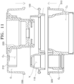
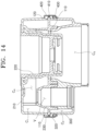
- FIGS. 11 to 14 are views schematically illustrating the process of assembling the top port apparatus for air suspension according to the second embodiment of the present disclosure.
- the top casing body 210 moves downward toward the middle casing body 110 in the state in which it is disposed above the middle casing body 110.
- the top casing body 210 moves downward by a predetermined distance or more, the bottom of the top casing body 210 comes into contact with the top of the middle casing body 110.
- top of the middle casing body 110 and the bottom of the top casing body 210 that are in contact with each other are integrally coupled to each other with adhesive or the like.
- the bottom casing body 310 moves upward toward the middle casing body 110 in the state in which it is disposed beneath the middle casing body 110.
- the top of the bottom casing body 310 comes into contact with the bottom of the middle casing body 110.
- the bottom of the middle casing body 110 and the top of the bottom casing body 310 that are in contact with each other are integrally coupled to each other with adhesive or the like.
- the middle casing body 110, the top casing body 210, and the bottom casing body 310 are coupled to each other, the lower surface of the end of the first extension part 230 and the upper surface of the end of the second extension part 320 are spaced apart from each other by a predetermined distance and face each other.
- the elastic member 410 is inserted between the ends of the first and second extension parts 230 and 320. Both upper and lower surfaces of the elastic member 410 are pressed against the lower surface of the end of the first extension part 230 and the upper surface of the end of the second extension part 320, respectively.
- the inner surface of the cover part 420 is disposed to face the circumferential surfaces of the ends of the first and second extension parts 230 and 320.
- the upper and lower ends of the cover part 420 are formed by press working, and pressed and fixed to the outer surfaces of the first and second extension parts 230 and 320.
- the upper end of the cover part 420 is deformed in a direction in which its inner surface is directed toward the outer surface of the first extension part 230 by the pressing force applied from a press tool (not shown) or the like, so that the upper end of the cover part 420 is pressed and fixed to the outer surface of the first extension part 230.
- the lower end of the cover part 420 is deformed in a direction in which its inner surface is directed toward the outer surface of the second extension part 320 by the pressing force applied from the press tool or the like.
- the inner surface of the cover part 420 comes into contact the outer surface of the guide member 430.
- the lower end of the cover part 420 is then deformed into a shape corresponding to the shape of the guide member 430, and pressed and fixed to the outer surfaces of the second extension part 320 and the guide member 430.
Landscapes
- Engineering & Computer Science (AREA)
- Mechanical Engineering (AREA)
- General Engineering & Computer Science (AREA)
- Physics & Mathematics (AREA)
- Geometry (AREA)
- Vehicle Body Suspensions (AREA)
- Fluid-Damping Devices (AREA)
Abstract
Description
- Exemplary embodiments of the present disclosure relate to a top port apparatus for air suspension, and more particularly, to a top port apparatus for air suspension with improved airtightness and durability.
- In general, suspension systems improve driving stability and ride comfort while a vehicle is traveling by performing functions such as absorbing vibration or shock transmitted from the road surface through an axle and balancing a vehicle body between the axle and the vehicle body.
- Among these suspension systems, air suspension may adjust an air pressure in an air spring by supporting a vehicle body with an air spring using the elasticity of compressed air and thus adjust the pressure according to the number of passengers or the condition of the road surface, thereby keeping the spring smooth at all times. Therefore, the air suspension is more advantageous for ride comfort.
- In addition, since the air suspension behaves nonlinearly in its characteristics, the pressure and volume of gas are inversely proportional at a certain temperature. Accordingly, the air suspension has a characteristic in that when a loading weight increases due to loading of people or cargo, the air is compressed to provide a higher repulsive force, whereas when the loading weight decreases, the repulsive force returns to its original force.
- Conventional air suspension has a complicated assembly process and a reduction in airtight performance because individual components are bonded by welding in different manners when manufacturing a top port coupled to a piston rod of a damper. Therefore, there is a need to address such an issue.
- The related art of the present disclosure is disclosed in
Korean Patent No. 10-1327048 (published on November 1, 2013 - This Summary is provided to introduce a selection of concepts in a simplified form that are further described below in the Detailed Description. This Summary is not intended to identify key features or essential features of the claimed subject matter, nor is it intended to be used as an aid in determining the scope of the claimed subject matter.
- Various embodiments are directed to a top port apparatus for air suspension with improved airtightness and durability.
- In an embodiment, a top port apparatus for air suspension may include a top casing connected to a vehicle body, a bottom casing disposed to face the top casing and connected to an air spring, and a sealing section configured to seal a gap between the top casing and the bottom casing.
- The top casing may include a top casing body, and a first extension part protruding outward from the top casing body. The bottom casing may include a bottom casing body coupled to the top casing body, and a second extension part protruding outward from the bottom casing body and disposed to face the first extension part.
- The sealing section may include an elastic member disposed between the first extension part and the second extension part, and a cover part disposed to face the elastic member and surround the first extension part and the second extension part.
- The cover part may have both ends that are deformed by press working and pressed to respective outer surfaces of the first second extension part and the second extension part.
- The sealing section may further include a guide member that is provided between at least one of the first second extension part or the second extension part and the cover part, and guides deformation of the cover part.
- In an another embodiment, a top port apparatus for air suspension may include: a middle casing, a top casing coupled to an upper side of the middle casing and connected to a vehicle body, a bottom casing coupled to a lower side of the middle casing and connected to an air spring, and a sealing section configured to seal a gap among the middle casing, the top casing, and the bottom casing.
- The middle casing may include a middle casing body disposed between the top casing and the bottom casing and having a valve chamber, and a seating part protruding outward from the middle casing body and extending along a circumferential surface of the middle casing body.
- The top casing may include a top casing body having a first chamber connecting with the valve chamber, and a first extension part protruding outward from the top casing body and seated on an upper side of the seating part. The bottom casing may include a bottom casing body having a second chamber and a third chamber connecting with the valve chamber, and a second extension part protruding outward from the bottom casing body and seated on a lower side of the seating part.
- The first extension part and the second extension part may each have a stepped cross-section.
- The first extension part and the second extension part may have ends that are spaced apart from and face each other.
- The sealing section may include an elastic member disposed between the first second extension part and the second extension part, and a cover part disposed to face the elastic member and surround the first extension part and the second extension part.
- The cover part may have both ends that are deformed by press working and pressed to respective outer surfaces of the first second extension part and the second extension part.
- The sealing section may further include a guide member that is provided between at least one of the first second extension part or the second extension part and the cover part, and guides deformation of the cover part.
- The guide member may gradually decrease in cross-sectional area as it is directed to the cover part.
- The guide member may be formed to be elastically deformable.
- As apparent from the above description, the top port apparatus for air suspension according to the present disclosure can simplify the assembly process and reduce costs to manufacture as the middle casing, the top casing, and the bottom casing are vertically stacked and coupled to each other.
- In addition, the top port apparatus for air suspension according to the present disclosure can double-block foreign substances from entering the middle casing, the top casing, and the bottom casing or air from leaking out of the middle casing, the top casing, and the bottom casing, by the stepped contact structure of the seating part and the first and second extension parts, and the sealing section.
- Moreover, the top port apparatus for air suspension according to the present disclosure can enhance the coupling force among the middle casing, the top casing, and the bottom casing by the cover part, and maintain the close contact of the elastic member with the first extension part and the second extension part.
- Furthermore, the top port apparatus for air suspension according to the present disclosure can block direct exposure of the elastic member to the outside by the cover part, thereby enhancing overall sealing performance of the sealing suction and preventing damage to the elastic member.
-
-
FIG. 1 is a perspective view schematically illustrating a configuration of a top port apparatus for air suspension according to a first embodiment of the present disclosure. -
FIG. 2 is a cross-sectional view schematically illustrating the configuration of the top port apparatus for air suspension according to the first embodiment of the present disclosure. -
FIG. 3 is an enlarged view schematically illustrating the configuration of the sealing section according to the embodiment of the first embodiment of present disclosure. -
FIGS. 4 to 7 are views schematically illustrating the process of assembling the top port apparatus for air suspension according to the first embodiment of the present disclosure. -
FIG. 8 is a perspective view schematically illustrating a configuration of a top port apparatus for air suspension according to a second embodiment of the present disclosure. -
FIG. 9 is a cross-sectional view schematically illustrating the configuration of the top port apparatus for air suspension according to the second embodiment of the present disclosure. -
FIG. 10 is an enlarged view schematically illustrating the configuration of the sealing section according to the embodiment of the second embodiment of present disclosure. -
FIGS. 11 to 14 are views schematically illustrating the process of assembling the top port apparatus for air suspension according to the second embodiment of the present disclosure. - The following detailed description is provided to assist the reader in gaining a comprehensive understanding of the methods, apparatuses, and/or systems described herein. However, various changes, modifications, and equivalents of the methods, apparatuses, and/or systems described herein will be apparent after an understanding of the disclosure of this application. For example, the sequences of operations described herein are merely examples, and are not limited to those set forth herein, but may be changed as will be apparent after an understanding of the disclosure of this application, with the exception of operations necessarily occurring in a certain order.
- The features described herein may be embodied in different forms and are not to be construed as being limited to the examples described herein. Rather, the examples described herein have been provided merely to illustrate some of the many possible ways of implementing the methods, apparatuses, and/or systems described herein that will be apparent after an understanding of the disclosure of this application.
- Advantages and features of the present disclosure and methods of achieving the advantages and features will be clear with reference to embodiments described in detail below together with the accompanying drawings. However, the present disclosure is not limited to the embodiments disclosed herein but will be implemented in various forms. The embodiments of the present disclosure are provided so that the present disclosure is completely disclosed, and a person with ordinary skill in the art can fully understand the scope of the present disclosure. The present disclosure will be defined only by the scope of the appended claims. Meanwhile, the terms used in the present specification are for explaining the embodiments, not for limiting the present disclosure.
- Terms, such as first, second, A, B, (a), (b) or the like, may be used herein to describe components. Each of these terminologies is not used to define an essence, order or sequence of a corresponding component but used merely to distinguish the corresponding component from other component(s). For example, a first component may be referred to as a second component, and similarly the second component may also be referred to as the first component.
- Throughout the specification, when a component is described as being "connected to," or "coupled to" another component, it may be directly "connected to," or "coupled to" the other component, or there may be one or more other components intervening therebetween. In contrast, when an element is described as being "directly connected to," or "directly coupled to" another element, there can be no other elements intervening therebetween.
- The singular forms "a", "an", and "the" are intended to include the plural forms as well, unless the context clearly indicates otherwise. It will be further understood that the terms "comprises/comprising" and/or "includes/including" when used herein, specify the presence of stated features, integers, steps, operations, elements, and/or components, but do not preclude the presence or addition of one or more other features, integers, steps, operations, elements, components and/or groups thereof.
-
FIG. 1 is a perspective view schematically illustrating a configuration of a top port apparatus for air suspension according to a first embodiment of the present disclosure.FIG. 2 is a cross-sectional view schematically illustrating the configuration of the top port apparatus for air suspension according to the first embodiment of the present disclosure. - Referring to
FIGS. 1 and2 , the top port apparatus for air suspension according to the present embodiment is configured to connect a vehicle body to a piston rod A of a shock absorber coupled with an axle and to adjust an air pressure within an air spring B, and includes atop casing 10, abottom casing 20, and asealing section 30. - The
top casing 10 defines an upper appearance of the top port apparatus for air suspension and is connected to the vehicle body. That is, thetop casing 10 functions to support the top port apparatus for air suspension as a whole with respect to the vehicle body. - The
top casing 10 according to the present embodiment may include atop casing body 11, arod mount 12, and afirst extension part 13. - The
top casing body 11 may have a cylindrical shape with an outer circumference forming a closed curve. Thetop casing body 11 may be made of a synthetic resin material and manufactured by injection molding. Thetop casing body 11 may have an upper surface detachably connected to the vehicle body by bolting or the like. The bottom of thetop casing body 11 is coupled to the top of thebottom casing 20 to be described later. In this case, the bottom of thetop casing body 11 may be integrally bonded to the top of thebottom casing body 20 with adhesive or the like. Thetop casing body 11 may have an upper chamber Ca, which is defined therein and filled with air. The upper chamber Ca may pass through the lower surface of thetop casing body 11. - The
rod mount 12 is coupled to thetop casing body 11 and supports the piston rod A. That is, therod mount 12 functions to connect the piston rod A to the vehicle body via thetop casing body 11. Therod mount 12 according to the present embodiment may have a cup shape with open upper and lower sides. Therod mount 12 may be made of a metal material such as aluminum. Therod mount 12 may be integrally coupled to thetop casing body 11 by insert injection or the like. Therod mount 12 may have a bottom protruding into thetop casing body 11. The top of the piston rod A may be inserted into therod mount 12 through the bottom of therod mount 12. The top of the piston rod A may be detachably fixed to therod mount 12 by bolting or the like. - The
first extension part 13 protrudes outward from thetop casing body 11. Thefirst extension part 13 according to the present embodiment may protrude from the outer surface of thetop casing body 11 in a direction perpendicular to the piston rod A. Thefirst extension part 13 may be made of the same material as thetop casing body 11. Thefirst extension part 13 may continuously extend along the circumferential surface of thetop casing body 11 to have a substantially ring shape. Thefirst extension part 13 may have a stepped cross-section. - The
bottom casing 20 is disposed to face thetop casing 10 and defines a lower appearance of the top port apparatus for air suspension. Thebottom casing 20 is connected to the air spring B, and functions to allow air to be transferred between the top port apparatus for air suspension and the air spring B. - The
bottom casing 20 according to the present embodiment includes abottom casing body 21 and asecond extension part 22. - The
bottom casing body 21 may have a cylindrical shape with an outer circumference forming a closed curve. Thebottom casing body 21 may be made of a synthetic resin material and manufactured by injection molding. The top of thebottom casing body 21 may be coupled to the bottom of thetop casing body 11. In this case, the top of thebottom casing body 21 may be integrally bonded to the bottom of thetop casing body 11 with adhesive or the like. The bottom of thebottom casing body 21 may be coupled to the top of the air spring B. - The
bottom casing body 310 may have therein a lower chamber Cb, which is filled with air and communicates with the upper chamber Ca, and a main chamber Cm, which is partitioned from the lower chamber Cb and communicates with the air spring B. The lower chamber Cb may communicate with the upper chamber Ca as thetop casing body 11 is coupled to thebottom casing body 12. The upper chamber Ca or the lower chamber Cb may be supplied with air via a nozzle (not shown) or the like from the outside. A valve (not shown) may be further installed between the lower chamber Cb and the main chamber Cm to allow air to be transferred between the lower chamber Cb and the main chamber Cm. - The
second extension part 22 protrudes outward from thebottom casing body 21. Thesecond extension part 22 according to the present embodiment may protrude from the outer surface of thebottom casing body 21 in a direction perpendicular to the piston rod A. Thesecond extension part 22 may be made of the same material as thebottom casing body 21. Thesecond extension part 22 may continuously extend along the circumferential surface of thebottom casing body 21 to have a substantially ring shape. The upper surface of thesecond extension part 22 is seated on the lower surface of thefirst extension part 13. Thesecond extension part 22 may have a stepped cross-section corresponding to the cross-section of thefirst extension part 13. Accordingly, the first andsecond extension parts top casing body 11 and thebottom casing body 21 together with the sealingsection 30 to be described later. - The sealing
section 30 seals a gap between thetop casing 10 and thebottom casing 20. That is, the sealingsection 30 functions to prevent foreign substances from entering or air from leaking into the gap between thetop casing 10 and thebottom casing 20. -
FIG. 3 is an enlarged view schematically illustrating the configuration of the sealing section according to the embodiment of the first embodiment of present disclosure. - Referring to
FIGS. 1 to 3 , the sealingsection 30 according to the present embodiment includes anelastic member 31 and acover part 32. - The
elastic member 31 is disposed between thefirst extension part 13 and thesecond extension part 22. Theelastic member 31 according to the present embodiment may have a substantially ring shape. Theelastic member 31 may be disposed between the lower surface of thefirst extension part 13 and the upper surface of thesecond extension part 22. Theelastic member 31 may be made of an elastically deformable material such as rubber or silicon. Theelastic member 31 may have a height greater than the distance between thefirst extension part 13 and thesecond extension part 22. Accordingly, the respective upper and lower surfaces of theelastic member 31 may be tightly pressed against the lower surface of the end of thefirst extension part 13 and the upper surface of the end of thesecond extension part 22 by elastic deformation. - The
cover part 32 is disposed to face theelastic member 31 and surround thefirst extension part 13 and thesecond extension part 22. That is, thecover part 32 is coupled to thefirst extension part 13 and thesecond extension part 22 to enhance the coupling force between thetop casing 10 and thebottom casing 20, and functions to maintain the close contact of theelastic member 31 with thefirst extension part 13 and thesecond extension part 22. In addition, thecover part 32 may block direct exposure of theelastic member 31 to the outside, thereby enhancing overall sealing performance of the sealingsection 30 and preventing damage to theelastic member 31. - The
cover part 32 according to the present embodiment may have a hollow ring shape with open upper and lower sides. The inner surface of thecover part 32 may surround the circumferential surfaces of the ends of the first andsecond extension parts elastic member 31. Depending on the shape of the first orsecond extension part cover part 32 may be disposed to face the elastic member with the first orsecond extension part elastic member 31. - The
cover part 32 may have a vertical height greater than the length between the top of thefirst extension part 13 and the bottom of thesecond extension part 22. Accordingly, thecover part 32 may have both upper and lower ends that protrude upward from thefirst extension part 13 and downward from thesecond extension part 22, respectively, in a state in which the inner surface of thecover part 32 faces the circumferential surfaces of the ends of the first andsecond extension parts cover part 32 may be deformed by press working and pressed and fixed to the outer surfaces of the first andsecond extension parts cover part 32 may be made of a metal material such as aluminum or steel so that it is variable in shape by press working while securing sufficient rigidity. - The sealing
section 30 according to the present embodiment may further include aguide member 33. - The
guide member 33 is provided between at least one of the first andsecond extension parts cover part 32 and guides deformation of thecover part 32 by press working. More specifically, theguide member 33 supports the inner surface of thecover part 32 during press working of thecover part 32 to guide the end of thecover part 32 to be deformed into a predetermined shape, and at the same time functions to distribute the pressurized load applied to the end of thecover part 32. Accordingly, theguide member 33 can prevent the end of thecover part 32 from being deformed and broken at an excessive angle, and prevent the pressurized load applied to the end of thecover part 32 from being concentrated locally. - An example in which the
guide member 33 is provided between thesecond extension part 22 and thecover part 32 will be described below. However, the present disclosure is not limited thereto. For example, theguide member 33 may be provided between thefirst extension part 13 and thecover part 32, or may consist of a plurality of guide members, which are provided between thefirst extension part 13 and thecover part 32 and between thesecond extension part 22 and thecover part 32, respectively. - The
guide member 33 according to the present embodiment may have a hollow ring shape with open upper and lower ends. Theguide member 33 may be disposed such that its inner surface is in contact with the outer surface of thebottom casing body 21 and its upper surface is in contact with the lower surface of thesecond extension part 22. Theguide member 33 may be fixed to thebottom casing body 21 or thesecond extension part 22 by welding, adhesive, or the like. Theguide member 33 may be made of an elastically deformable material such as rubber, silicon, or synthetic resin. - Hereinafter, a process of assembling the top port apparatus for air suspension according to the first embodiment of the present disclosure will be described in detail.
-
FIGS. 4 to 7 are views schematically illustrating the process of assembling the top port apparatus for air suspension according to the first embodiment of the present disclosure. - Referring to
FIGS. 4 to 7 , thetop casing body 11 and thebottom casing body 21 may be disposed such that their respective lower and upper surfaces, which are opened by the respective upper chamber Ca and lower chamber Cb, face each other vertically. - Subsequently, the
top casing body 11 and thebottom casing body 21 move in close proximity to each other, so the bottom of thetop casing body 11 comes into contact with the top of thebottom casing body 21. - The bottom of the
top casing body 11 and the top of thebottom casing body 21 that are in contact with each other may be integrally coupled to each other with adhesive or the like. - In this case, as the bottom of the
top casing body 11 comes into contact with the top of thebottom casing body 21 with theelastic member 31 being disposed between thetop casing body 11 and thebottom casing body 21, both upper and lower surfaces of theelastic member 31 may be tightly pressed and fixed to the lower surface of thefirst extension part 13 and the upper surface of thesecond extension part 22, respectively. - Subsequently, the inner surface of the
cover part 32 is disposed to face the circumferential surfaces of the ends of the first andsecond extension parts - The upper and lower ends of the
cover part 32 are formed by press working, and pressed and fixed to the outer surfaces of the first andsecond extension parts - More specifically, the upper end of the
cover part 32 is deformed in a direction in which its inner surface is directed toward the outer surface of thefirst extension part 13 by the pressing force applied from a press tool (not shown) or the like, so that the upper end of thecover part 420 is pressed and fixed to the outer surface of thefirst extension part 13. - The lower end of the
cover part 32 is deformed in a direction in which its inner surface is directed toward the outer surface of thesecond extension part 22 by the pressing force applied from the press tool or the like. - As the lower end of the
cover part 32 is deformed at a predetermined angle or more, the inner surface of thecover part 32 may come into contact the outer surface of theguide member 33. The lower end of thecover part 32 may then be deformed into a shape corresponding to the shape of theguide member 33, and pressed and fixed to the outer surfaces of theguide member 33. - Hereinafter, a top port apparatus for air suspension according to a second embodiment of the present disclosure will be described.
-
FIG. 8 is a perspective view schematically illustrating a configuration of a top port apparatus for air suspension according to a second embodiment of the present disclosure.FIG. 9 is a cross-sectional view schematically illustrating the configuration of the top port apparatus for air suspension according to the second embodiment of the present disclosure. - Referring to
FIGS. 8 and9 , the top port apparatus for air suspension, which is designated by reference numeral 1, according to the embodiment of the present disclosure is configured to connect a vehicle body to a piston rod A of a shock absorber coupled with an axle and to adjust an air pressure within an air spring B, and may include amiddle casing 100, atop casing 200, abottom casing 300, and sealingsection 400. - Since the piston rod A and the air spring B correspond to well-known components in a typical air suspension structure, a detailed description thereof will be omitted.
- The
middle casing 100 is disposed between the vehicle body and the air spring B, and interconnects thetop casing 200 and thebottom casing 300. - The
middle casing 100 according to the embodiment of the present disclosure may include amiddle casing body 110 and aseating part 120. - The
middle casing body 110 defines a schematic external appearance of themiddle casing 100 and is disposed between thetop casing 200 and thebottom casing 300. Themiddle casing body 110 according to the embodiment of the present disclosure may have a cylindrical shape with an outer circumference forming a closed curve. The cross-section of themiddle casing body 110 perpendicular to the piston rod A may be asymmetrical. Themiddle casing body 110 may be made of a synthetic resin material and manufactured by injection molding. Themiddle casing body 110 may have therein a valve chamber V in which a solenoid valve (not shown) is installed to control the connection between a first chamber C1, a second chamber C2, and a third chamber C3, which will be described later, so that the stiffness of the air spring B is variable. - The
seating part 120 protrudes outward from themiddle casing body 110 and supports afirst extension part 230 and asecond extension part 320 which will be described later. Theseating part 120 according to the embodiment of the present disclosure may protrude from the outer surface of themiddle casing body 110 in a direction perpendicular to the piston rod A. Theseating part 120 may be made of the same material as themiddle casing body 110. Theseating part 120 may continuously extend along the circumferential surface of themiddle casing body 110 to have a substantially ring shape. Theseating part 120 may have a stepped cross-section in which its height gradually increases toward the end thereof. - The
top casing 200 is coupled to the top of themiddle casing 100 and connected to the vehicle body. That is, thetop casing 200 functions to support the top port apparatus for air suspension 1 according to the embodiment of the present disclosure as a whole with respect to the vehicle body. - The
top casing 200 according to the embodiment of the present disclosure may include atop casing body 210, arod mount 220, and afirst extension part 230. - The
top casing body 210 defines a schematic external appearance of thetop casing 200 and is disposed above themiddle casing body 110. Thetop casing body 210 according to the embodiment of the present disclosure may have a cylindrical shape with an outer circumference forming a closed curve. The cross-section of thetop casing body 210 perpendicular to the piston rod A may be asymmetrical, more specifically, may have a shape corresponding to the cross-section of themiddle casing body 110. Thetop casing body 210 may be made of a synthetic resin material and manufactured by injection molding. Thetop casing body 210 has an upper surface detachably connected to the vehicle body by bolting or the like. The bottom of thetop casing body 210 is coupled to the top of themiddle casing body 110. In this case, the bottom of thetop casing body 210 may be integrally bonded to the top of themiddle casing body 110 with adhesive or the like. Thetop casing body 210 may have therein a first chamber C1, which is filled with air and connects with the valve chamber V, and a fourth chamber C4, which is partitioned from the first chamber C1 and connects with the valve chamber V and a third chamber C3 to be described later. - The
rod mount 220 is coupled to thetop casing body 210 and supports the piston rod A. That is, therod mount 220 functions to connect the piston rod A to the vehicle body via thetop casing body 210. Therod mount 220 according to the embodiment of the present disclosure may have a cup shape with open upper and lower sides. Therod mount 220 may be made of a metal material such as aluminum. Therod mount 220 may be integrally coupled to thetop casing body 210 by insert injection or the like. Therod mount 220 has a bottom protruding into thetop casing body 210. The top of the piston rod A is inserted into therod mount 220 through the bottom of therod mount 220. The top of the piston rod A may be detachably fixed to therod mount 220 by bolting or the like. - The
first extension part 230 protrudes outward from thetop casing body 210 and is seated on the upper side of theseating part 120. Thefirst extension part 230 according to the embodiment of the present disclosure may protrude from the outer surface of thetop casing body 210 in a direction perpendicular to the piston rod A. Thefirst extension part 230 may be made of the same material as thetop casing body 210. Thefirst extension part 230 may continuously extend along the circumferential surface of thetop casing body 210 to have a substantially ring shape. The lower surface of thefirst extension part 230 is seated on the upper surface of theseating part 120. Thefirst extension part 230 may have a stepped cross-section in which its height gradually decreases toward the end thereof so as to correspond to the cross-section of theseating part 120. Accordingly, thefirst extension part 230 and theseating part 120 may form a structure in which they come into close contact with each other in a stepwise manner, thereby preventing foreign substances from entering or air from leaking between themiddle casing body 110 and thetop casing body 210 together with thesealing section 400. - The
bottom casing 300 is coupled to the bottom of themiddle casing 100 and connected to the air spring B. That is, thebottom casing 300 functions to allow air to be transferred between the air spring B and the top port apparatus for air suspension 1 according to the embodiment of the present disclosure. - The
bottom casing 300 according to the embodiment of the present disclosure may include abottom casing body 310 and asecond extension part 320. - The
bottom casing body 310 defines a schematic external appearance of thebottom casing 300 and is disposed beneath themiddle casing body 110. Thebottom casing body 310 according to the embodiment of the present disclosure may have a cylindrical shape with an outer circumference forming a closed curve. The cross-section of thebottom casing body 310 perpendicular to the piston rod A may be asymmetrical, more specifically, may have a shape corresponding to the cross-section of themiddle casing body 110. Thebottom casing body 310 may be made of a synthetic resin material and manufactured by injection molding. The top of thebottom casing body 310 is coupled to the bottom of themiddle casing body 110. In this case, the top of thebottom casing body 310 may be integrally bonded to the bottom of themiddle casing body 110 with an adhesive or the like. The bottom of thebottom casing body 310 is coupled to the top of the air spring B. Thebottom casing body 310 may have therein a second chamber C2, which is filled with air and connects with the valve chamber V, and a third chamber C3, which is partitioned from the second chamber C2 and connects with the fourth chamber C4 and the air spring B. - The
second extension part 320 protrudes outward from thebottom casing body 310 and is seated on the lower side of theseating part 120. Thesecond extension part 320 according to the embodiment of the present disclosure may protrude from the outer surface of thebottom casing body 310 in a direction perpendicular to the piston rod A. Thesecond extension part 320 may be made of the same material as thebottom casing body 310. Thesecond extension part 320 may continuously extend along the circumferential surface of thebottom casing body 310 to have a substantially ring shape. The upper surface of thesecond extension part 320 is seated on the lower surface of theseating part 120. Thesecond extension part 320 may have a stepped cross-section in which its height gradually decreases toward the end thereof so as to correspond to the cross-section of theseating part 120. Accordingly, thesecond extension part 320 and theseating part 120 may form a structure in which they come into close contact with each other in a stepwise manner, thereby preventing foreign substances from entering or air from leaking between themiddle casing body 110 and thebottom casing body 310 together with thesealing section 400. The upper surface of the end of thesecond extension part 320 is spaced apart from and disposed to face the lower surface of the end of thefirst extension part 230. Accordingly, a space in which anelastic member 410 to be described later is installed may be provided between the ends of the first andsecond extension parts - The
sealing section 400 seals a gap among themiddle casing 100, thetop casing 200, and thebottom casing 300. That is, thesealing section 400 functions to prevent foreign substances from entering or air from leaking into the gap among themiddle casing 100, thetop casing 200, and thebottom casing 300. -
FIG. 10 is an enlarged view schematically illustrating the configuration of the sealing section according to the second embodiment of the present disclosure. - Referring to
FIGS. 8 to 10 , thesealing section 400 according to the embodiment of the present disclosure may include anelastic member 410, acover part 420. - The
elastic member 410 is disposed between the ends of the first andsecond extension parts elastic member 410 according to the embodiment of the present disclosure may have a substantially ring shape. Theelastic member 410 is disposed between the lower surface of the end of thefirst extension part 230 and the upper surface of the end of thesecond extension part 320. Theelastic member 410 may be made of an elastically deformable material such as rubber or silicon. Theelastic member 410 has a height greater than the distance between thefirst extension part 230 and thesecond extension part 320. Accordingly, the respective upper and lower surfaces of theelastic member 410 may be tightly pressed against the lower surface of the end of thefirst extension part 230 and the upper surface of the end of thesecond extension part 320 by elastic deformation. - The
cover part 420 is disposed to face theelastic member 410 and surround thefirst extension part 230 and thesecond extension part 320. That is, thecover part 420 is coupled to thefirst extension part 230 and thesecond extension part 320 to enhance the coupling force among themiddle casing 100, thetop casing 200, and thebottom casing 300, and functions to maintain the close contact of theelastic member 410 with thefirst extension part 230 and thesecond extension part 320. In addition, thecover part 420 may block direct exposure of theelastic member 410 to the outside, thereby enhancing overall sealing performance of thesealing section 400 and preventing damage to theelastic member 410. Thecover part 420 according to the embodiment of the present disclosure may have a hollow ring shape with open upper and lower sides. The inner surface of thecover part 420 surrounds the circumferential surfaces of the ends of the first andsecond extension parts elastic member 410. Thecover part 420 has a vertical height greater than the length between the top of thefirst extension part 230 and the bottom of thesecond extension part 320. Accordingly, thecover part 420 may have both upper and lower ends that protrude upward from thefirst extension part 230 and downward from thesecond extension part 320, respectively, in a state in which the inner surface of thecover part 420 faces the circumferential surfaces of the ends of the first andsecond extension parts cover part 420 may be deformed by press working and pressed and fixed to the outer surfaces of the first andsecond extension parts cover part 420 may be made of a metal material such as aluminum or steel so that it is variable in shape by press working while securing sufficient rigidity. - The
sealing section 400 according to the present embodiment may further include aguide member 430. - The
guide member 430 is provided between at least one of the first andsecond extension parts cover part 420 and guides deformation of thecover part 420 by press working. More specifically, theguide member 430 supports the inner surface of thecover part 420 during press working of thecover part 420 to guide the end of thecover part 420 to be deformed into a predetermined shape, and at the same time functions to distribute the pressurized load applied to the end of thecover part 420. Accordingly, theguide member 430 can prevent the end of thecover part 420 from being deformed and broken at an excessive angle, and prevent the pressurized load applied to the end of thecover part 420 from being concentrated locally. - An example in which the
guide member 430 is provided between thesecond extension part 320 and thecover part 420 will be described below. However, the present disclosure is not limited thereto. For example, theguide member 430 may be provided between thefirst extension part 230 and thecover part 420, or may consist of a plurality of guide members, which are provided between thefirst extension part 230 and thecover part 420 and between thesecond extension part 320 and thecover part 420, respectively. - The
guide member 430 according to the present embodiment may have a hollow ring shape with open upper and lower ends. Theguide member 430 is disposed such that its inner surface is in contact with the outer surface of thebottom casing body 310 and its upper surface is in contact with the lower surface of thesecond extension part 320. Theguide member 430 may be fixed to thebottom casing body 310 or thesecond extension part 320 by welding, adhesive, or the like. Theguide member 430 may have a cross-sectional shape in which its cross-sectional area gradually decreases as theguide member 430 is directed to cover part, for example, as shown inFIG 10 , directed downward. Theguide member 430 may be made of an elastically deformable material such as rubber, silicon, or synthetic resin. - Hereinafter, a process of assembling the top port apparatus for air suspension 1 according to the embodiment of the present disclosure will be described in detail.
-
FIGS. 11 to 14 are views schematically illustrating the process of assembling the top port apparatus for air suspension according to the second embodiment of the present disclosure. - Referring to
FIGS. 11 to 14 , thetop casing body 210 moves downward toward themiddle casing body 110 in the state in which it is disposed above themiddle casing body 110. - As the
top casing body 210 moves downward by a predetermined distance or more, the bottom of thetop casing body 210 comes into contact with the top of themiddle casing body 110. - The top of the
middle casing body 110 and the bottom of thetop casing body 210 that are in contact with each other are integrally coupled to each other with adhesive or the like. - In addition, the
bottom casing body 310 moves upward toward themiddle casing body 110 in the state in which it is disposed beneath themiddle casing body 110. - As the
bottom casing body 310 moves upward by a predetermined distance or more, the top of thebottom casing body 310 comes into contact with the bottom of themiddle casing body 110. - The bottom of the
middle casing body 110 and the top of thebottom casing body 310 that are in contact with each other are integrally coupled to each other with adhesive or the like. - As the
middle casing body 110, thetop casing body 210, and thebottom casing body 310 are coupled to each other, the lower surface of the end of thefirst extension part 230 and the upper surface of the end of thesecond extension part 320 are spaced apart from each other by a predetermined distance and face each other. - The
elastic member 410 is inserted between the ends of the first andsecond extension parts elastic member 410 are pressed against the lower surface of the end of thefirst extension part 230 and the upper surface of the end of thesecond extension part 320, respectively. - Subsequently, the inner surface of the
cover part 420 is disposed to face the circumferential surfaces of the ends of the first andsecond extension parts - The upper and lower ends of the
cover part 420 are formed by press working, and pressed and fixed to the outer surfaces of the first andsecond extension parts - More specifically, the upper end of the
cover part 420 is deformed in a direction in which its inner surface is directed toward the outer surface of thefirst extension part 230 by the pressing force applied from a press tool (not shown) or the like, so that the upper end of thecover part 420 is pressed and fixed to the outer surface of thefirst extension part 230. - The lower end of the
cover part 420 is deformed in a direction in which its inner surface is directed toward the outer surface of thesecond extension part 320 by the pressing force applied from the press tool or the like. - As the lower end of the
cover part 420 is deformed at a predetermined angle or more, the inner surface of thecover part 420 comes into contact the outer surface of theguide member 430. The lower end of thecover part 420 is then deformed into a shape corresponding to the shape of theguide member 430, and pressed and fixed to the outer surfaces of thesecond extension part 320 and theguide member 430. - While the present disclosure has been described with respect to the embodiments illustrated in the drawings, it will be obvious to those skilled in the art that such embodiments are provided by way of example only. It will be understood by those skilled in the art that various modifications and other equivalent embodiments may be made without departing from the spirit and scope of the disclosure as defined in the following claims.
- Therefore, the technical protection scope of the present disclosure should be defined by the following claims.
Claims (15)
- A top port apparatus for air suspension, comprising:a top casing connected to a vehicle body;a bottom casing disposed to face the top casing and connected to an air spring; anda sealing section configured to seal a gap between the top casing and the bottom casing.
- The top port apparatus for air suspension according to claim 1,wherein the top casing comprises:a top casing body; anda first extension part protruding outward from the top casing body, andwherein the bottom casing comprises:a bottom casing body coupled to the top casing body; anda second extension part protruding outward from the bottom casing body and disposed to face the first extension part.
- The top port apparatus for air suspension according to claim 2, wherein the sealing section comprises:an elastic member disposed between the first extension part and the second extension part; anda cover part disposed to face the elastic member and surround the first extension part and the second extension part.
- The top port apparatus for air suspension according to claim 3, wherein the cover part has both ends that are deformed by press working and pressed to respective outer surfaces of the first second extension part and the second extension part.
- The top port apparatus for air suspension according to claim 4, wherein the sealing section further comprises a guide member that is provided between at least one of the first extension part or the second extension part and the cover part, and guides deformation of the cover part.
- A top port apparatus for air suspension, comprising:a middle casing;a top casing coupled to an upper side of the middle casing and connected to a vehicle body;a bottom casing coupled to a lower side of the middle casing and connected to an air spring; anda sealing section configured to seal a gap among the middle casing, the top casing, and the bottom casing.
- The top port apparatus for air suspension according to claim 6, wherein the middle casing comprises:a middle casing body disposed between the top casing and the bottom casing and having a valve chamber; anda seating part protruding outward from the middle casing body and extending along a circumferential surface of the middle casing body.
- The top port apparatus for air suspension according to claim 7,wherein the top casing comprises:a top casing body having a first chamber connecting with the valve chamber; anda first extension part protruding outward from the top casing body and seated on an upper side of the seating part, andwherein the bottom casing comprises:a bottom casing body having a second chamber and a third chamber connecting with the valve chamber; anda second extension part protruding outward from the bottom casing body and seated on a lower side of the seating part.
- The top port apparatus for air suspension according to claim 8, wherein the first extension part and the second extension part each have a stepped cross-section.
- The top port apparatus for air suspension according to claim 8 or 9, wherein the first extension part and the second extension part have ends that are spaced apart from and face each other.
- The top port apparatus for air suspension according to any one of claims 8 to 10, wherein the sealing section comprises:an elastic member disposed between the first second extension part and the second extension part; anda cover part disposed to face the elastic member and surround the first extension part and the second extension part.
- The top port apparatus for air suspension according to claim 11, wherein the cover part has both ends that are deformed by press working and pressed to respective outer surfaces of the first second extension part and the second extension part.
- The top port apparatus for air suspension according to claim 12, wherein the sealing section further comprises a guide member that is provided between at least one of the first extension part or the second extension part and the cover part, and guides deformation of the cover part.
- The top port apparatus for air suspension according to claim 13, wherein the guide member gradually decreases in cross-sectional area as it is directed to the cover part.
- The top port apparatus for air suspension according to claim 13 or 14, wherein the guide member is formed to be elastically deformable.
Priority Applications (2)
| Application Number | Priority Date | Filing Date | Title |
|---|---|---|---|
| EP23177862.2A EP4474179B1 (en) | 2023-06-07 | 2023-06-07 | Top port apparatus for an air suspension |
| KR1020230076793A KR20240174006A (en) | 2023-06-07 | 2023-06-15 | Top port apparatus for air suspension |
Applications Claiming Priority (1)
| Application Number | Priority Date | Filing Date | Title |
|---|---|---|---|
| EP23177862.2A EP4474179B1 (en) | 2023-06-07 | 2023-06-07 | Top port apparatus for an air suspension |
Publications (2)
| Publication Number | Publication Date |
|---|---|
| EP4474179A1 true EP4474179A1 (en) | 2024-12-11 |
| EP4474179B1 EP4474179B1 (en) | 2025-08-20 |
Family
ID=86732103
Family Applications (1)
| Application Number | Title | Priority Date | Filing Date |
|---|---|---|---|
| EP23177862.2A Active EP4474179B1 (en) | 2023-06-07 | 2023-06-07 | Top port apparatus for an air suspension |
Country Status (2)
| Country | Link |
|---|---|
| EP (1) | EP4474179B1 (en) |
| KR (1) | KR20240174006A (en) |
Citations (4)
| Publication number | Priority date | Publication date | Assignee | Title |
|---|---|---|---|---|
| US20030067103A1 (en) * | 2001-10-04 | 2003-04-10 | Easter Mark R. | Dual rate air spring |
| US20040119212A1 (en) * | 2002-12-06 | 2004-06-24 | Jens-Uwe Gleu | Air spring cover and method of making the same |
| KR101327048B1 (en) | 2007-12-13 | 2013-11-20 | 현대자동차주식회사 | Air Spring for Vehicle |
| WO2016110357A1 (en) * | 2015-01-09 | 2016-07-14 | Trelleborgvibracoustic Gmbh | Composite part and air spring component containing such a composite part |
-
2023
- 2023-06-07 EP EP23177862.2A patent/EP4474179B1/en active Active
- 2023-06-15 KR KR1020230076793A patent/KR20240174006A/en active Pending
Patent Citations (4)
| Publication number | Priority date | Publication date | Assignee | Title |
|---|---|---|---|---|
| US20030067103A1 (en) * | 2001-10-04 | 2003-04-10 | Easter Mark R. | Dual rate air spring |
| US20040119212A1 (en) * | 2002-12-06 | 2004-06-24 | Jens-Uwe Gleu | Air spring cover and method of making the same |
| KR101327048B1 (en) | 2007-12-13 | 2013-11-20 | 현대자동차주식회사 | Air Spring for Vehicle |
| WO2016110357A1 (en) * | 2015-01-09 | 2016-07-14 | Trelleborgvibracoustic Gmbh | Composite part and air spring component containing such a composite part |
Also Published As
| Publication number | Publication date |
|---|---|
| EP4474179B1 (en) | 2025-08-20 |
| KR20240174006A (en) | 2024-12-16 |
Similar Documents
| Publication | Publication Date | Title |
|---|---|---|
| US11536344B2 (en) | Valve and shock absorber | |
| US5924528A (en) | Load depending damping assembly | |
| US4234172A (en) | Hydraulic shock absorber and spring combination | |
| CN108779828B (en) | Shock absorber with shock valve | |
| US4342446A (en) | Self-leveling viscous elastic damper | |
| US5040774A (en) | Hydraulic damping bushing | |
| US20120049428A1 (en) | Dual path hydraulic strut mounts and vehicular suspension systems including the same | |
| CN102102730A (en) | Asymmetrical intake damper valve | |
| JP7154341B2 (en) | Bellows for air suspension assemblies and air suspension assemblies | |
| US20020063024A1 (en) | Hydraulic shock absorber | |
| US3212768A (en) | Hydro-pneumatic shock absorber | |
| CN111433486B (en) | Air spring strut assembly with reinforcement core in cover | |
| US20140060985A1 (en) | Hydraulic shock absorber and valve | |
| EP4474179B1 (en) | Top port apparatus for an air suspension | |
| CN119712761A (en) | Shock absorbers, suspension systems and vehicles | |
| WO2023023141A1 (en) | Synthetic elastomeric air spring without reinforcing fibers | |
| CN113027973B (en) | Gas cup for damper assembly and damper assembly | |
| KR20220037568A (en) | Sealing Structure For Top Port | |
| KR102845963B1 (en) | Shock absorber | |
| CN101243266A (en) | Asymmetric inlet damper valve | |
| EP3074658B1 (en) | Damping fluid devices, systems and methods | |
| JP7769531B2 (en) | Valves and shock absorbers | |
| KR100664383B1 (en) | Separator tube of damping force variable shock absorber | |
| KR102764354B1 (en) | Top mount and top mount assembly for air spring for vehicle | |
| JP2023106804A (en) | buffer |
Legal Events
| Date | Code | Title | Description |
|---|---|---|---|
| PUAI | Public reference made under article 153(3) epc to a published international application that has entered the european phase |
Free format text: ORIGINAL CODE: 0009012 |
|
| STAA | Information on the status of an ep patent application or granted ep patent |
Free format text: STATUS: REQUEST FOR EXAMINATION WAS MADE |
|
| 17P | Request for examination filed |
Effective date: 20240528 |
|
| AK | Designated contracting states |
Kind code of ref document: A1 Designated state(s): AL AT BE BG CH CY CZ DE DK EE ES FI FR GB GR HR HU IE IS IT LI LT LU LV MC ME MK MT NL NO PL PT RO RS SE SI SK SM TR |
|
| RIC1 | Information provided on ipc code assigned before grant |
Ipc: F16F 9/36 20060101ALI20250225BHEP Ipc: F16F 9/08 20060101ALI20250225BHEP Ipc: B60G 15/12 20060101ALI20250225BHEP Ipc: F16J 15/02 20060101ALI20250225BHEP Ipc: F16F 9/54 20060101ALI20250225BHEP Ipc: F16F 9/05 20060101ALI20250225BHEP Ipc: B60G 11/30 20060101ALI20250225BHEP Ipc: B60G 11/28 20060101AFI20250225BHEP |
|
| GRAP | Despatch of communication of intention to grant a patent |
Free format text: ORIGINAL CODE: EPIDOSNIGR1 |
|
| STAA | Information on the status of an ep patent application or granted ep patent |
Free format text: STATUS: GRANT OF PATENT IS INTENDED |
|
| INTG | Intention to grant announced |
Effective date: 20250407 |
|
| GRAS | Grant fee paid |
Free format text: ORIGINAL CODE: EPIDOSNIGR3 |
|
| GRAA | (expected) grant |
Free format text: ORIGINAL CODE: 0009210 |
|
| STAA | Information on the status of an ep patent application or granted ep patent |
Free format text: STATUS: THE PATENT HAS BEEN GRANTED |
|
| AK | Designated contracting states |
Kind code of ref document: B1 Designated state(s): AL AT BE BG CH CY CZ DE DK EE ES FI FR GB GR HR HU IE IS IT LI LT LU LV MC ME MK MT NL NO PL PT RO RS SE SI SK SM TR |
|
| P01 | Opt-out of the competence of the unified patent court (upc) registered |
Free format text: CASE NUMBER: UPC_APP_0105_4474179/2025 Effective date: 20250710 |
|
| REG | Reference to a national code |
Ref country code: GB Ref legal event code: FG4D |
|
| REG | Reference to a national code |
Ref country code: CH Ref legal event code: EP |
|
| REG | Reference to a national code |
Ref country code: IE Ref legal event code: FG4D |
|
| REG | Reference to a national code |
Ref country code: DE Ref legal event code: R096 Ref document number: 602023005820 Country of ref document: DE |
|
| REG | Reference to a national code |
Ref country code: NL Ref legal event code: MP Effective date: 20250820 |
|
| PG25 | Lapsed in a contracting state [announced via postgrant information from national office to epo] |
Ref country code: IS Free format text: LAPSE BECAUSE OF FAILURE TO SUBMIT A TRANSLATION OF THE DESCRIPTION OR TO PAY THE FEE WITHIN THE PRESCRIBED TIME-LIMIT Effective date: 20251220 |
|
| PG25 | Lapsed in a contracting state [announced via postgrant information from national office to epo] |
Ref country code: NO Free format text: LAPSE BECAUSE OF FAILURE TO SUBMIT A TRANSLATION OF THE DESCRIPTION OR TO PAY THE FEE WITHIN THE PRESCRIBED TIME-LIMIT Effective date: 20251120 |
|
| REG | Reference to a national code |
Ref country code: LT Ref legal event code: MG9D |
|
| PG25 | Lapsed in a contracting state [announced via postgrant information from national office to epo] |
Ref country code: PT Free format text: LAPSE BECAUSE OF FAILURE TO SUBMIT A TRANSLATION OF THE DESCRIPTION OR TO PAY THE FEE WITHIN THE PRESCRIBED TIME-LIMIT Effective date: 20251222 |
|
| PG25 | Lapsed in a contracting state [announced via postgrant information from national office to epo] |
Ref country code: FI Free format text: LAPSE BECAUSE OF FAILURE TO SUBMIT A TRANSLATION OF THE DESCRIPTION OR TO PAY THE FEE WITHIN THE PRESCRIBED TIME-LIMIT Effective date: 20250820 |
|
| PG25 | Lapsed in a contracting state [announced via postgrant information from national office to epo] |
Ref country code: HR Free format text: LAPSE BECAUSE OF FAILURE TO SUBMIT A TRANSLATION OF THE DESCRIPTION OR TO PAY THE FEE WITHIN THE PRESCRIBED TIME-LIMIT Effective date: 20250820 Ref country code: NL Free format text: LAPSE BECAUSE OF FAILURE TO SUBMIT A TRANSLATION OF THE DESCRIPTION OR TO PAY THE FEE WITHIN THE PRESCRIBED TIME-LIMIT Effective date: 20250820 |
|
| PG25 | Lapsed in a contracting state [announced via postgrant information from national office to epo] |
Ref country code: GR Free format text: LAPSE BECAUSE OF FAILURE TO SUBMIT A TRANSLATION OF THE DESCRIPTION OR TO PAY THE FEE WITHIN THE PRESCRIBED TIME-LIMIT Effective date: 20251121 |
|
| PG25 | Lapsed in a contracting state [announced via postgrant information from national office to epo] |
Ref country code: SE Free format text: LAPSE BECAUSE OF FAILURE TO SUBMIT A TRANSLATION OF THE DESCRIPTION OR TO PAY THE FEE WITHIN THE PRESCRIBED TIME-LIMIT Effective date: 20250820 |
|
| PG25 | Lapsed in a contracting state [announced via postgrant information from national office to epo] |
Ref country code: LV Free format text: LAPSE BECAUSE OF FAILURE TO SUBMIT A TRANSLATION OF THE DESCRIPTION OR TO PAY THE FEE WITHIN THE PRESCRIBED TIME-LIMIT Effective date: 20250820 |
|
| PG25 | Lapsed in a contracting state [announced via postgrant information from national office to epo] |
Ref country code: PL Free format text: LAPSE BECAUSE OF FAILURE TO SUBMIT A TRANSLATION OF THE DESCRIPTION OR TO PAY THE FEE WITHIN THE PRESCRIBED TIME-LIMIT Effective date: 20250820 Ref country code: BG Free format text: LAPSE BECAUSE OF FAILURE TO SUBMIT A TRANSLATION OF THE DESCRIPTION OR TO PAY THE FEE WITHIN THE PRESCRIBED TIME-LIMIT Effective date: 20250820 |
|
| PG25 | Lapsed in a contracting state [announced via postgrant information from national office to epo] |
Ref country code: RS Free format text: LAPSE BECAUSE OF FAILURE TO SUBMIT A TRANSLATION OF THE DESCRIPTION OR TO PAY THE FEE WITHIN THE PRESCRIBED TIME-LIMIT Effective date: 20251120 |
|
| PG25 | Lapsed in a contracting state [announced via postgrant information from national office to epo] |
Ref country code: ES Free format text: LAPSE BECAUSE OF FAILURE TO SUBMIT A TRANSLATION OF THE DESCRIPTION OR TO PAY THE FEE WITHIN THE PRESCRIBED TIME-LIMIT Effective date: 20250820 |
|
| REG | Reference to a national code |
Ref country code: AT Ref legal event code: MK05 Ref document number: 1826960 Country of ref document: AT Kind code of ref document: T Effective date: 20250820 |
|
| PG25 | Lapsed in a contracting state [announced via postgrant information from national office to epo] |
Ref country code: SM Free format text: LAPSE BECAUSE OF FAILURE TO SUBMIT A TRANSLATION OF THE DESCRIPTION OR TO PAY THE FEE WITHIN THE PRESCRIBED TIME-LIMIT Effective date: 20250820 |
|
| PG25 | Lapsed in a contracting state [announced via postgrant information from national office to epo] |
Ref country code: DK Free format text: LAPSE BECAUSE OF FAILURE TO SUBMIT A TRANSLATION OF THE DESCRIPTION OR TO PAY THE FEE WITHIN THE PRESCRIBED TIME-LIMIT Effective date: 20250820 |
|
| PG25 | Lapsed in a contracting state [announced via postgrant information from national office to epo] |
Ref country code: AT Free format text: LAPSE BECAUSE OF FAILURE TO SUBMIT A TRANSLATION OF THE DESCRIPTION OR TO PAY THE FEE WITHIN THE PRESCRIBED TIME-LIMIT Effective date: 20250820 |
|
| PG25 | Lapsed in a contracting state [announced via postgrant information from national office to epo] |
Ref country code: IT Free format text: LAPSE BECAUSE OF FAILURE TO SUBMIT A TRANSLATION OF THE DESCRIPTION OR TO PAY THE FEE WITHIN THE PRESCRIBED TIME-LIMIT Effective date: 20250820 |
|
| PG25 | Lapsed in a contracting state [announced via postgrant information from national office to epo] |
Ref country code: CZ Free format text: LAPSE BECAUSE OF FAILURE TO SUBMIT A TRANSLATION OF THE DESCRIPTION OR TO PAY THE FEE WITHIN THE PRESCRIBED TIME-LIMIT Effective date: 20250820 |
|
| PG25 | Lapsed in a contracting state [announced via postgrant information from national office to epo] |
Ref country code: SK Free format text: LAPSE BECAUSE OF FAILURE TO SUBMIT A TRANSLATION OF THE DESCRIPTION OR TO PAY THE FEE WITHIN THE PRESCRIBED TIME-LIMIT Effective date: 20250820 Ref country code: EE Free format text: LAPSE BECAUSE OF FAILURE TO SUBMIT A TRANSLATION OF THE DESCRIPTION OR TO PAY THE FEE WITHIN THE PRESCRIBED TIME-LIMIT Effective date: 20250820 |
|
| REG | Reference to a national code |
Ref country code: DE Ref legal event code: R097 Ref document number: 602023005820 Country of ref document: DE |
|
| PLBE | No opposition filed within time limit |
Free format text: ORIGINAL CODE: 0009261 |
|
| STAA | Information on the status of an ep patent application or granted ep patent |
Free format text: STATUS: NO OPPOSITION FILED WITHIN TIME LIMIT |
|
| PG25 | Lapsed in a contracting state [announced via postgrant information from national office to epo] |
Ref country code: LT Free format text: LAPSE BECAUSE OF FAILURE TO SUBMIT A TRANSLATION OF THE DESCRIPTION OR TO PAY THE FEE WITHIN THE PRESCRIBED TIME-LIMIT Effective date: 20250820 |
|
| REG | Reference to a national code |
Ref country code: CH Ref legal event code: L10 Free format text: ST27 STATUS EVENT CODE: U-0-0-L10-L00 (AS PROVIDED BY THE NATIONAL OFFICE) Effective date: 20260701 |
|
| PGFP | Annual fee paid to national office [announced via postgrant information from national office to epo] |
Ref country code: DE Payment date: 20260420 Year of fee payment: 4 |
|
| PGFP | Annual fee paid to national office [announced via postgrant information from national office to epo] |
Ref country code: FR Payment date: 20260421 Year of fee payment: 4 |
|
| 26N | No opposition filed |
Effective date: 20260521 |