EP4474170A1 - System and method for tire treadwear sensing - Google Patents
System and method for tire treadwear sensing Download PDFInfo
- Publication number
- EP4474170A1 EP4474170A1 EP24178774.6A EP24178774A EP4474170A1 EP 4474170 A1 EP4474170 A1 EP 4474170A1 EP 24178774 A EP24178774 A EP 24178774A EP 4474170 A1 EP4474170 A1 EP 4474170A1
- Authority
- EP
- European Patent Office
- Prior art keywords
- treadwear
- tire
- sensor
- tread
- tube
- Prior art date
- Legal status (The legal status is an assumption and is not a legal conclusion. Google has not performed a legal analysis and makes no representation as to the accuracy of the status listed.)
- Granted
Links
Images




Classifications
-
- B—PERFORMING OPERATIONS; TRANSPORTING
- B60—VEHICLES IN GENERAL
- B60C—VEHICLE TYRES; TYRE INFLATION; TYRE CHANGING; CONNECTING VALVES TO INFLATABLE ELASTIC BODIES IN GENERAL; DEVICES OR ARRANGEMENTS RELATED TO TYRES
- B60C5/00—Inflatable pneumatic tyres or inner tubes
- B60C5/12—Inflatable pneumatic tyres or inner tubes without separate inflatable inserts, e.g. tubeless tyres with transverse section open to the rim
- B60C5/14—Inflatable pneumatic tyres or inner tubes without separate inflatable inserts, e.g. tubeless tyres with transverse section open to the rim with impervious liner or coating on the inner wall of the tyre
-
- B—PERFORMING OPERATIONS; TRANSPORTING
- B60—VEHICLES IN GENERAL
- B60C—VEHICLE TYRES; TYRE INFLATION; TYRE CHANGING; CONNECTING VALVES TO INFLATABLE ELASTIC BODIES IN GENERAL; DEVICES OR ARRANGEMENTS RELATED TO TYRES
- B60C11/00—Tyre tread bands; Tread patterns; Anti-skid inserts
- B60C11/24—Wear-indicating arrangements
- B60C11/243—Tread wear sensors, e.g. electronic sensors
-
- B—PERFORMING OPERATIONS; TRANSPORTING
- B29—WORKING OF PLASTICS; WORKING OF SUBSTANCES IN A PLASTIC STATE IN GENERAL
- B29D—PRODUCING PARTICULAR ARTICLES FROM PLASTICS OR FROM SUBSTANCES IN A PLASTIC STATE
- B29D30/00—Producing pneumatic or solid tyres or parts thereof
- B29D30/0061—Accessories, details or auxiliary operations not otherwise provided for
-
- B—PERFORMING OPERATIONS; TRANSPORTING
- B29—WORKING OF PLASTICS; WORKING OF SUBSTANCES IN A PLASTIC STATE IN GENERAL
- B29D—PRODUCING PARTICULAR ARTICLES FROM PLASTICS OR FROM SUBSTANCES IN A PLASTIC STATE
- B29D30/00—Producing pneumatic or solid tyres or parts thereof
- B29D30/06—Pneumatic tyres or parts thereof (e.g. produced by casting, moulding, compression moulding, injection moulding, centrifugal casting)
-
- B—PERFORMING OPERATIONS; TRANSPORTING
- B60—VEHICLES IN GENERAL
- B60C—VEHICLE TYRES; TYRE INFLATION; TYRE CHANGING; CONNECTING VALVES TO INFLATABLE ELASTIC BODIES IN GENERAL; DEVICES OR ARRANGEMENTS RELATED TO TYRES
- B60C19/00—Tyre parts or constructions not otherwise provided for
- B60C2019/004—Tyre sensors other than for detecting tyre pressure
Definitions
- treadwear can be indicative of other issues with a vehicle. Uneven treadwear on a tire may indicate an improper alignment, overinflation, underinflation, or potentially an issue with the vehicle's suspension.
- the invention relates to a tire in accordance with claim 1, to a method in accordance with claim 6 and to an apparatus in accordance with claim 11.
- Axial and “axially” mean lines or directions that are parallel to the axis of rotation of the tire.
- Bead means that part of the tire comprising an annular tensile member wrapped by ply cords and shaped, with or without other reinforcement elements such as flippers, chippers, apexes, toe guards and chafers, to fit the design rim.
- Carcass means the tire structure apart from the belt structure, tread, undertread, and sidewall rubber over the plies, but including the beads.
- “Footprint” means the contact patch or area of contact created by the tire tread with a flat surface, such as the ground, as the tire rotates or rolls.
- Innerliner means the layer or layers of elastomer or other material that form the inside surface of a tubeless tire and that contain the inflating fluid within the tire.
- “Lateral” means an axial direction.
- Ring and radially mean lines or directions that are perpendicular to the axis of rotation of the tire.
- TPMS means a tire pressure monitoring system, which is an electronic system that measures the internal pressure of a tire and is capable of communicating the pressure to a processor that is mounted on the vehicle and/or is in electronic communication with electronic systems of the vehicle.
- Thread element or “traction element” means a rib or a block element defined by a shape having adjacent grooves.
- a vehicle 100 having one or more tires 103.
- Each tire 103 includes a treadwear sensor 106 which is capable of indicating the wear on the tire 103.
- each one of the tires 103 on the vehicle 100 may include one or more of the treadwear sensors 106.
- the vehicle 100 is depicted as a commercial truck, the vehicle 100 may comprise any other type of vehicle which employs tires, where the commercial truck is presented as an example. To this end, the vehicle 100 may comprise other vehicles falling into various categories such as passenger vehicles, off-road vehicles, and the like, in which such vehicles may include a greater or lesser number of tires 103 than are shown in FIG. 1 .
- the tire 103 includes a pair of bead areas 109, each one of which is formed with a bead core 113 that is embedded in the respective bead areas 109.
- Each one of a pair of sidewalls 116 extends radially outwardly from a respective bead area 109 to a ground-contacting tread 119.
- the tread 119 is formed with multiple tread elements 123 or tread blocks and defines a radially outer surface 126.
- the tire 103 is reinforced by a carcass 129 that toroidally extends from one bead area 109 to the other bead area 109.
- An innerliner 133 is formed on the inner or inside surface of the carcass 129.
- the tire 103 is mounted on the flange of a wheel or rim forming an internal cavity 136.
- At least one treadwear sensor 106 is inserted in the tire 103.
- the treadwear sensor 106 detects certain real-time parameters of the tire 103 and is preferably coupled with a pressure sensor to sense the inflation pressure within a cavity 136 of the tire 103.
- the treadwear sensor 106 may be included in a commercially-available tire pressure monitoring system (TPMS) module or sensing unit.
- TPMS tire pressure monitoring system
- the treadwear sensor 106 may be comprised of metal, rubber, or some other material.
- the friction force between the material of the treadwear sensor 106 and the rubber of the tire 103 is enough to keep the treadwear sensor 106 in place while the tire 103 is in use.
- an adhesive is used to secure the treadwear sensor 106 in the tire 103.
- multiple treadwear sensors 106 are included in the tire 103 at various locations in the tread 119. Having multiple treadwear sensors 106 allows for detection of wear even in the case of uneven treadwear. For example, uneven treadwear may result in one treadwear sensor 106 being triggered while others are not.
- the treadwear sensor 106 is installed in the tire 103 before the tire 103 is mounted on the wheel. In some embodiments, the treadwear sensor 106 is inserted in a green tire and cured into place. In other embodiments, the treadwear sensor 106 is inserted into the tire 103 after it is cured. Each treadwear sensor 106 includes a base plate 139 and a tube 143. The tube 143 of the treadwear sensor 106 is inserted into the tire 103 from the direction of the cavity 136 through the innerliner 133 and the carcass 129 and into the tread element 123. In some embodiments, the treadwear sensor 106 may be integrally molded as part of the innerliner 133 of the tire 103.
- the base plate 139 engages a radially inward side of the innerliner 133 to provide a positive mechanical stop for the treadwear sensor 106.
- the base plate 139 also provides a seal about the treadwear sensor 106 to prevent the treadwear sensor 106 from dislodging.
- the tube 143 extends through the tread element 123 and may have an end which is flush with the outer surface 126 of the tread element 123. In other embodiments, an end of the tube 143 is not flush with the outer surface 126 of the tread element 123 but is disposed at a wear depth within the tread 119.
- the tube 143 is formed of a material which has an air barrier greater than or equal to that of the innerliner 133, is a durable material, and is capable of bonding with the rubber components of the tire 103.
- the tube 143 is formed of a material that includes mechanical properties, such as shear modulus, which are similar to those of the material of the tread 119.
- the tube 143 is formed of a metal or other dissimilar material.
- the treadwear sensor 106 is designed such that the end of the tube 143 wears with the tread 119 until the tread 119 reaches a wear depth.
- the wear depth on the tube 143 coincides with the beginning of the channel 146.
- the leak of the treadwear sensor 106 is designed to be slow and unique compared to other common tire leaks, such as punctures or tears.
- the treadwear sensor 106 can be designed such that the leak changes with the degree of wear on the tire 103.
- a pressure sensor can detect the leak signature of the treadwear sensor 106 and work with other systems to alert a user that the tread 119 is worn.
- the leak of the treadwear sensor 106 causes the tire 103 to go flat before the treadwear causes hazardous driving conditions.
- FIG. 3 shown is cross-sectional view of the treadwear sensor 106 in the tread 119 of a tire 103.
- the tread 119 is in an unworn state.
- the tread 119 is in a worn state.
- the treadwear sensor 106 is inserted through the innerliner 133 of the tire 103 and may extend to the radially outer surface 126 of the tire 103.
- the tube 143 extends through various components such as a belt package, the undertread, and other components of the tire 103.
- the treadwear sensor 106 comprises a base plate 139 and a tube 143 extending from the base plate 139.
- the base plate 139 lays flush against a radially inward side of the innerliner 133.
- the base plate 139 is connected to a pressure sensor.
- the tube 143 extends away from the base plate 139 in a substantially perpendicular direction. In other embodiments, the tube 143 extends away from the base plate 139 at an angle between 80 and 45 degrees.
- the tube 143 extends through the innerliner 133 and may extend through the tread element 123 to the radially outer surface 126 of the tire 103.
- the tube 143 includes a channel 146 which extends at least partially through the tube 143.
- the channel 146 extends through the tube 143 to a wear depth.
- the wear depth can be indicative of the level of treadwear which has occurred.
- the wear depth can be the depth in the tread 119 that, when reached, signifies the need to replace the tire 103.
- the channel 146 is at least partially filled with a semi-permeable filler 149.
- the semi-permeable filler 149 can have a lower air permeability than a hollow channel 146 to allow for a slow leak.
- the semi-permeable filler 149 can be a polymer, foam, plastic, or some other material which is permeable to air.
- the channel 146 is hollow.
- the diameter of the channel 146 can be optimized to result in a leaking rate ( ⁇ P ⁇ t , where ⁇ P is the change in pressure ( P ) and ⁇ t is the change in time ( t )) based on the following equation: ⁇ P 1 ⁇ t ⁇ R ⁇ ⁇ P 2 ⁇ t
- ⁇ P 1 ⁇ t is the minimum pressure drop rate that a pressure sensor can detect.
- ⁇ P 2 ⁇ t is an unsafe leaking rate for a tire 103.
- R is a design range of a detected leaking rate for detecting a worn tire 103 safely.
- R is related to the diameter, length, and semi-permeable filler 149 of the channel 146.
- the tube 143 includes a solid end 153 which may be flush with the radially outer surface 126 of the tread 119.
- the solid end 153 is located within the tread 119 at a wear depth.
- the solid end 153 of the tube 143 wears at the same rate as the tread 119. When the tread 119 wears beyond the wear depth, the solid end 153 is worn away, and the channel 146 is exposed.
- the solid end 153 of the tube 143 is made of the same rubber as the tread 119.
- the tread 119 of the tire 103 is worn such that the solid end 153 of the tube 143 has been eroded down to the channel 146.
- air will begin to leak through channel 146.
- air leaks slowly through the semi-permeable filler 149 disposed inside the channel 146.
- a pressure sensor coupled with the treadwear sensor 106 can detect the leak signature produced by the treadwear sensor 106.
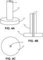
- FIG. 4A shows a perspective view of the worn treadwear sensor 106.
- FIG. 4B shows a cross-sectional side view of the treadwear sensor 106.
- FIG. 4C shows a bottom view of the treadwear sensor 106.
- the treadwear sensor 106 includes a base plate 139 and a tube 143 which has a hollow channel 146. While depicted in FIG. 4 as separate components, the base plate 139 and the tube 143 may be formed as one contiguous piece. In the worn state, the channel 146 extends from a hole in the base plate 139 through the tube 143 allowing air to flow through the treadwear sensor 106. While FIG. 4A shows a perspective view of the worn treadwear sensor 106.
- FIG. 4B shows a cross-sectional side view of the treadwear sensor 106.
- FIG. 4C shows a bottom view of the treadwear sensor 106.
- the treadwear sensor 106 includes a base plate 139 and a tube 143 which has a hollow channel 146. While depict
- the base plate 139, the tube 143, and the channel 146 depicts the base plate 139, the tube 143, and the channel 146 as circular or cylindrical, many other shapes may be possible in other embodiments.
- the tube 143 and/or channel 146 can be rectangular, conical, triangular, or any other similar shape as can be appreciated.
- the base plate 139 may be circular, oblong, rectangular, triangular, or any other similar shape as can be appreciated.
- the treadwear sensor 106 includes a first semi-permeable filler 149a and a second semi-permeable filler 149b, where the first semi-permeable filler 149a is a different material than the second semi-permeable filler 149b.
- the first semi-permeable filler 149a surrounds the second semi-permeable filler 149b and both fillers extend the length of the channel 146.
- the first semi-permeable filler 149a and the second semi-permeable filler 149b are layered throughout the channel 146. Further embodiments may include third, fourth, or more semi-permeable fillers 149 as well.
- the tube 143 includes a first tube portion 143a and a second tube portion 143b, where the first tube portion 143a has a different diameter than the second tube portion 143b.
- the channel 146 has a first diameter in the first tube portion 143a and a second diameter in the second tube portion 143b.
- the channel 146 in the first tube portion 143a is filled with a first semi-permeable filler 149a and the channel 146 in the second tube portion 143b is filled with a second semi-permeable filler 149b.
- both the first tube portion 143a and the second tube portion 143b are filled with the same semi-permeable filler 149.
- Further embodiments may include having third, fourth, or more tube portions 143 with channels 146 of varying diameters and potentially various semi-permeable fillers 149 as well.
- the first tube portion 143a is longer than the second tube portion 143b.
- the second tube portion 143b is longer than the first tube portion 143a.
- tube portions 143a, 143b, channel 146 diameters, semi-permeable fillers 149, or other features which generate a unique leak signature, distinct from that of a typical tire puncture or tear, can be used to form the treadwear sensor 106.
- the leak signature of air flowing through the channel 146 changes as treadwear progresses.
- the leak through the channel 146 will be a first value.
- the wear progresses such that the first tube portion 143a is exposed through the tread 119
- the leak through the channel will increase in value. In this manner, the first leak value, the second leak value, and/or a change in leak values could be detected to inform a user that the tread 119 is too low.
- the tube 143 of the treadwear sensor 106 also wears.
- the distal end of the tube 143 is eroded to the beginning of the channel 146, creating a passageway for air to flow from the cavity 136 of the tire 103 out through the channel 146.
- the predefined wear depth can be the minimum recommended tread depth of the tire 103.
- the leak caused by the treadwear sensor 106 signifies that the minimum tread depth has been reached, and thus indicates when replacement or retreading of the tire 103 should take place.
- the tire 103 with a treadwear sensor 106 indicates tire wear with components that are mounted within the tire 103 and does not require sensors that are external to the tire 103.
- the tire 103 with a treadwear sensor 106 provides a direct wear sensor system for a vehicle tire 103 that includes a structure which is easy to install in the tire 103, withstands the operating environment of the tire 103, and accurately indicates tire wear in a repeatable manner.
- the present disclosure also includes a method of determining wear of a tire using a treadwear sensor 106. This method includes steps in accordance with the description that is presented above and shown in FIGS. 1 through 5 .
- a single treadwear sensor 106 may be disposed in the tread 119 of the tire 103, or multiple treadwear sensors 106 may be disposed in the tread 119 about the tire 103.
- the treadwear sensor 106 may be inserted into the tread element 123 before or after curing of the tire 103.
- the tire 103 includes a predefined minimum tread depth. As a tire 103 is put into service on a vehicle over time, the tread 119 will wear down.
- the predefined minimum tread depth is a minimum recommended tread depth at which the tire 103 can be placed into service.
- the tread 119 of the tire 103 thus includes a sacrificial portion that is expected to wear away over time while the tire 103 is in service.
- the treadwear sensor 106 may be located at any lateral position on the tread 119 of the tire 103.
- the treadwear sensor 106 may be placed at positions across the tread 119 from each other or any other position on the tread 119 or in a given tread element 123 as shown.
- the treadwear sensors 106 may be positioned to detect treadwear at any lateral location on the tread 119 of a tire 103.
- Embodiment 1 is a tire comprising an innerliner, a plurality of belts layered adjacent to the innerliner, a tread adjacent to the plurality of belts opposite the innerliner, and a treadwear sensor positioned in the innerliner.
- the treadwear sensor comprises a base plate on an interior side of the innerliner, and a tube extending from the base plate through the innerliner and the plurality of belts to a first wear depth in the tread. When the tread is worn to the first wear depth, an end of the tube is exposed through the tire.
- Embodiment 2 is the tire of embodiment 1 further comprising a plurality of the treadwear sensors dispersed throughout the innerliner.
- Embodiment 3 is the tire of embodiments 1 or 2, wherein the treadwear sensor further comprises a channel extending through the tube from a hole in the base plate to a distal end of the tube. When the tread is worn to the first wear depth, an amount of air passes through the channel.
- Embodiment 4 is the tire of embodiments 2 or 3 wherein the treadwear sensor further comprises a semi-permeable filler within the channel. When the tread is worn to the first wear depth, a reduced amount of air passes through the semi-permeable filler within the channel.
- Embodiment 5 is the tire of embodiments 2 through 4 wherein the channel further comprises at least a first portion having a first diameter and at least a second portion having a second diameter.
- Embodiment 6 is the tire of embodiment 5 wherein the treadwear sensor further comprises a first semi-permeable filler within the first portion of the channel.
- Embodiment 7 is the tire of embodiment 6 wherein the treadwear sensor further comprises a second semi-permeable filler within the second portion of the channel.
- Embodiment 8 is a method comprising providing a treadwear sensor having a tube and a base plate disposed at a first end of the tube, where the treadwear sensor configured to produce a unique leak signature when a tread is worn to a wear depth. The method further comprises inserting the tube of the treadwear sensor through an innerliner of a tire such that a second end of the tube is disposed in a tread of the tire at the wear depth and the base plate is adjacent to the innerliner.
- Embodiment 9 is the method of embodiment 8 wherein the tire is a green tire.
- the method of embodiment 9 further comprises curing the green tire around the tube of the treadwear sensor.
- Embodiment 10 is the method of embodiments 8 or 9 further comprising filling at least a portion of the tube with a semi-permeable filler.
- Embodiment 11 is the method of embodiments 8 through 10 further comprising positioning the treadwear sensor adjacent to a pressure sensor on the innerliner of the tire.
- Embodiment 12 is the method of embodiments 8 through 11 further comprising attaching a pressure sensor to the base plate of the treadwear sensor.
- Embodiment 13 is the method of embodiments 8 through 12 wherein the treadwear sensor is one of a plurality of treadwear sensors. The method of embodiment 13 further comprises inserting the plurality of treadwear sensors in the tire such that the plurality of treadwear sensors are dispersed across the tread.
- Embodiment 14 is an apparatus comprising a base having a hole, an elongated member extending from the base, and a channel connecting the hold of the base to a distal end of the elongated member.
- Embodiment 15 is the apparatus of embodiment 14 further comprising a first semi-permeable filler within the channel.
- Embodiment 16 is the apparatus of embodiments 14 or 15 further comprising a second semi-permeable filler extending through the channel and being disposed within the first semi-permeable filler.
- Embodiment 17 is the apparatus of embodiments 14 through 16 further comprising a pressure sensor attached to the base.
- Embodiment 18 is the apparatus of embodiments 14 through 17 wherein the channel comprises at least a first portion having a first diameter and at least a second portion having a second diameter.
- Embodiment 19 is the apparatus of embodiment 18 further comprising a first semi-permeable filler in the first portion of the channel.
- Embodiment 20 is the apparatus of embodiment 18 or 19 further comprising a second semi-permeable filler in the second portion of the channel.
Landscapes
- Engineering & Computer Science (AREA)
- Mechanical Engineering (AREA)
- Tires In General (AREA)
Abstract
Description
- As tires are used on a vehicle, the rubber in the tread gradually breaks away causing the tread to become shallower and decreasing overall tire performance. When the tread is too shallow, the tire may become unsafe in certain driving conditions. For example, shallow tread decreases traction in wet or icy conditions. Further, shallow tread may impact braking distance and the likelihood of having a tire blowout. In addition to causing unsafe driving conditions, treadwear can be indicative of other issues with a vehicle. Uneven treadwear on a tire may indicate an improper alignment, overinflation, underinflation, or potentially an issue with the vehicle's suspension.
- The invention relates to a tire in accordance with claim 1, to a method in accordance with claim 6 and to an apparatus in accordance with claim 11.
- Dependent claims refer to preferred embodiments of the invention.
- Many aspects of the present disclosure can be better understood with reference to the following drawings. The components in the drawings are not necessarily to scale, with emphasis instead being placed upon clearly illustrating the principles of the disclosure. Moreover, in the drawings, like reference numerals designate corresponding parts throughout the several views.
-
FIG. 1 is a drawing of a vehicle with one or more tires that include a treadwear sensor according to various embodiments of the present disclosure. -
FIG. 2 is a perspective cross-sectional view of a tire shown inFIG. 1 , including multiple treadwear sensors according to various embodiments of the present disclosure. -
FIG. 3A is a cross-sectional perspective view of the treadwear sensor installed in the tire shown inFIG. 2 , with the tire in an unworn state according to various embodiments of the present disclosure.FIG. 3B is a cross-sectional perspective view of the treadwear sensor installed in the tire shown inFIG. 2 , with the tire in a worn state according to various embodiments of the present disclosure. -
FIGS. 4A-C depict various views of the treadwear sensor ofFIG. 3 according to various embodiments of the present disclosure. -
FIG. 5A-C depict cross-sectional views of the treadwear sensor ofFIG. 3 according to various embodiments of the present disclosure. -
FIG. 6 is a partial cross-sectional perspective view of a portion of a tire ofFIG. 2 including a treadwear sensor, with the tire in a worn state according to various embodiments of the present disclosure. - "Axial" and "axially" mean lines or directions that are parallel to the axis of rotation of the tire.
- "Axially inward" and "axially inwardly" refer to an axial direction that is toward the axial center of the tire.
- "Axially outward" and "axially outwardly" refer to an axial direction that is away from the axial center of the tire.
- "Bead" means that part of the tire comprising an annular tensile member wrapped by ply cords and shaped, with or without other reinforcement elements such as flippers, chippers, apexes, toe guards and chafers, to fit the design rim.
- "Carcass" means the tire structure apart from the belt structure, tread, undertread, and sidewall rubber over the plies, but including the beads.
- "Footprint" means the contact patch or area of contact created by the tire tread with a flat surface, such as the ground, as the tire rotates or rolls.
- "Innerliner" means the layer or layers of elastomer or other material that form the inside surface of a tubeless tire and that contain the inflating fluid within the tire.
- "Lateral" means an axial direction.
- "Radial" and "radially" mean lines or directions that are perpendicular to the axis of rotation of the tire.
- "Radially inward" and "radially inwardly" refer to a radial direction that is toward the central axis of rotation of the tire.
- "Radially outward" and "radially outwardly" refer to a radial direction that is away from the central axis of rotation of the tire.
- "TPMS" means a tire pressure monitoring system, which is an electronic system that measures the internal pressure of a tire and is capable of communicating the pressure to a processor that is mounted on the vehicle and/or is in electronic communication with electronic systems of the vehicle.
- "Tread element" or "traction element" means a rib or a block element defined by a shape having adjacent grooves.
- With particular reference to
FIG. 1 , avehicle 100 is shown having one ormore tires 103. Eachtire 103 includes atreadwear sensor 106 which is capable of indicating the wear on thetire 103. According to various embodiments, each one of thetires 103 on thevehicle 100 may include one or more of thetreadwear sensors 106. While thevehicle 100 is depicted as a commercial truck, thevehicle 100 may comprise any other type of vehicle which employs tires, where the commercial truck is presented as an example. To this end, thevehicle 100 may comprise other vehicles falling into various categories such as passenger vehicles, off-road vehicles, and the like, in which such vehicles may include a greater or lesser number oftires 103 than are shown inFIG. 1 . - Turning to
FIG. 2 , shown is a cross sectional view of thetire 103 according to various embodiments. Thetire 103 includes a pair ofbead areas 109, each one of which is formed with abead core 113 that is embedded in therespective bead areas 109. Each one of a pair ofsidewalls 116 extends radially outwardly from arespective bead area 109 to a ground-contactingtread 119. Thetread 119 is formed withmultiple tread elements 123 or tread blocks and defines a radiallyouter surface 126. Thetire 103 is reinforced by acarcass 129 that toroidally extends from onebead area 109 to theother bead area 109. Aninnerliner 133 is formed on the inner or inside surface of thecarcass 129. Thetire 103 is mounted on the flange of a wheel or rim forming aninternal cavity 136. - According to one embodiment, at least one
treadwear sensor 106 is inserted in thetire 103. Thetreadwear sensor 106 detects certain real-time parameters of thetire 103 and is preferably coupled with a pressure sensor to sense the inflation pressure within acavity 136 of thetire 103. Thetreadwear sensor 106 may be included in a commercially-available tire pressure monitoring system (TPMS) module or sensing unit. Thetreadwear sensor 106 may be comprised of metal, rubber, or some other material. In some embodiments, the friction force between the material of thetreadwear sensor 106 and the rubber of thetire 103 is enough to keep thetreadwear sensor 106 in place while thetire 103 is in use. In other embodiments, an adhesive is used to secure thetreadwear sensor 106 in thetire 103. In some embodiments,multiple treadwear sensors 106 are included in thetire 103 at various locations in thetread 119. Havingmultiple treadwear sensors 106 allows for detection of wear even in the case of uneven treadwear. For example, uneven treadwear may result in onetreadwear sensor 106 being triggered while others are not. - The
treadwear sensor 106 is installed in thetire 103 before thetire 103 is mounted on the wheel. In some embodiments, thetreadwear sensor 106 is inserted in a green tire and cured into place. In other embodiments, thetreadwear sensor 106 is inserted into thetire 103 after it is cured. Eachtreadwear sensor 106 includes abase plate 139 and atube 143. Thetube 143 of thetreadwear sensor 106 is inserted into thetire 103 from the direction of thecavity 136 through theinnerliner 133 and thecarcass 129 and into thetread element 123. In some embodiments, thetreadwear sensor 106 may be integrally molded as part of theinnerliner 133 of thetire 103. Once thetube 143 is inserted into theinnerliner 133, thebase plate 139 engages a radially inward side of theinnerliner 133 to provide a positive mechanical stop for thetreadwear sensor 106. Thebase plate 139 also provides a seal about thetreadwear sensor 106 to prevent thetreadwear sensor 106 from dislodging. - In some embodiments, the
tube 143 extends through thetread element 123 and may have an end which is flush with theouter surface 126 of thetread element 123. In other embodiments, an end of thetube 143 is not flush with theouter surface 126 of thetread element 123 but is disposed at a wear depth within thetread 119. In some embodiments, thetube 143 is formed of a material which has an air barrier greater than or equal to that of theinnerliner 133, is a durable material, and is capable of bonding with the rubber components of thetire 103. In some embodiments, thetube 143 is formed of a material that includes mechanical properties, such as shear modulus, which are similar to those of the material of thetread 119. Such similarity ensures that there are no rigid components within the structure of thetire 103, thereby enabling thetube 143 of thetreadwear sensor 106 to behave like a compatible plug in thetread element 123. However, in other embodiments, thetube 143 is formed of a metal or other dissimilar material. - The
treadwear sensor 106 is designed such that the end of thetube 143 wears with thetread 119 until thetread 119 reaches a wear depth. The wear depth on thetube 143 coincides with the beginning of thechannel 146. Thus, when thetread 119 is worn down to the wear depth, thechannel 146 of thetreadwear sensor 106 becomes exposed to the air, and air begins to leak through thetreadwear sensor 106. The leak of thetreadwear sensor 106 is designed to be slow and unique compared to other common tire leaks, such as punctures or tears. Thetreadwear sensor 106 can be designed such that the leak changes with the degree of wear on thetire 103. In some embodiments, a pressure sensor can detect the leak signature of thetreadwear sensor 106 and work with other systems to alert a user that thetread 119 is worn. In some embodiments, the leak of thetreadwear sensor 106 causes thetire 103 to go flat before the treadwear causes hazardous driving conditions. - Turning to
FIG. 3 , shown is cross-sectional view of thetreadwear sensor 106 in thetread 119 of atire 103. InFIG 3A , thetread 119 is in an unworn state. InFIG. 3B , thetread 119 is in a worn state. Thetreadwear sensor 106 is inserted through theinnerliner 133 of thetire 103 and may extend to the radiallyouter surface 126 of thetire 103. In this respect, thetube 143 extends through various components such as a belt package, the undertread, and other components of thetire 103. Thetreadwear sensor 106 comprises abase plate 139 and atube 143 extending from thebase plate 139. Thebase plate 139 lays flush against a radially inward side of theinnerliner 133. In some embodiments, thebase plate 139 is connected to a pressure sensor. In some embodiments, thetube 143 extends away from thebase plate 139 in a substantially perpendicular direction. In other embodiments, thetube 143 extends away from thebase plate 139 at an angle between 80 and 45 degrees. - As shown in
FIG. 3A , thetube 143 extends through theinnerliner 133 and may extend through thetread element 123 to the radiallyouter surface 126 of thetire 103. Thetube 143 includes achannel 146 which extends at least partially through thetube 143. In some embodiments, thechannel 146 extends through thetube 143 to a wear depth. The wear depth can be indicative of the level of treadwear which has occurred. For example, the wear depth can be the depth in thetread 119 that, when reached, signifies the need to replace thetire 103. - In some embodiments, the
channel 146 is at least partially filled with asemi-permeable filler 149. Thesemi-permeable filler 149 can have a lower air permeability than ahollow channel 146 to allow for a slow leak. Thesemi-permeable filler 149 can be a polymer, foam, plastic, or some other material which is permeable to air. In other embodiments, thechannel 146 is hollow. In such embodiments, the diameter of thechannel 146 can be optimized to result in a leaking rate (

- In this equation,


tire 103. R is a design range of a detected leaking rate for detecting aworn tire 103 safely. R is related to the diameter, length, andsemi-permeable filler 149 of thechannel 146. - The
tube 143 includes asolid end 153 which may be flush with the radiallyouter surface 126 of thetread 119. In some embodiments, thesolid end 153 is located within thetread 119 at a wear depth. Thesolid end 153 of thetube 143 wears at the same rate as thetread 119. When thetread 119 wears beyond the wear depth, thesolid end 153 is worn away, and thechannel 146 is exposed. In some embodiments, thesolid end 153 of thetube 143 is made of the same rubber as thetread 119. - In
FIG. 3B , thetread 119 of thetire 103 is worn such that thesolid end 153 of thetube 143 has been eroded down to thechannel 146. When thetread 119 is worn and thechannel 146 is exposed to air through thetire 103, air will begin to leak throughchannel 146. In some embodiments, air leaks slowly through thesemi-permeable filler 149 disposed inside thechannel 146. A pressure sensor coupled with thetreadwear sensor 106 can detect the leak signature produced by thetreadwear sensor 106. - Moving on to
FIG. 4 , shown is atreadwear sensor 106 in a worn state.FIG. 4A shows a perspective view of theworn treadwear sensor 106.FIG. 4B shows a cross-sectional side view of thetreadwear sensor 106.FIG. 4C shows a bottom view of thetreadwear sensor 106. Thetreadwear sensor 106 includes abase plate 139 and atube 143 which has ahollow channel 146. While depicted inFIG. 4 as separate components, thebase plate 139 and thetube 143 may be formed as one contiguous piece. In the worn state, thechannel 146 extends from a hole in thebase plate 139 through thetube 143 allowing air to flow through thetreadwear sensor 106. WhileFIG. 4 depicts thebase plate 139, thetube 143, and thechannel 146 as circular or cylindrical, many other shapes may be possible in other embodiments. For example, thetube 143 and/orchannel 146 can be rectangular, conical, triangular, or any other similar shape as can be appreciated. Similarly, thebase plate 139 may be circular, oblong, rectangular, triangular, or any other similar shape as can be appreciated. - Referring next to
FIG. 5 , shown are cross-sectional side views of various embodiments of thetreadwear sensor 106. According to one embodiment, shown inFIG. 5A , thetreadwear sensor 106 includes a firstsemi-permeable filler 149a and a secondsemi-permeable filler 149b, where the firstsemi-permeable filler 149a is a different material than the secondsemi-permeable filler 149b. In some embodiments, the firstsemi-permeable filler 149a surrounds the secondsemi-permeable filler 149b and both fillers extend the length of thechannel 146. In other embodiments, the firstsemi-permeable filler 149a and the secondsemi-permeable filler 149b are layered throughout thechannel 146. Further embodiments may include third, fourth, or moresemi-permeable fillers 149 as well. - According to another embodiment, shown in
FIG. 5B , thetube 143 includes afirst tube portion 143a and asecond tube portion 143b, where thefirst tube portion 143a has a different diameter than thesecond tube portion 143b. In some embodiments, thechannel 146 has a first diameter in thefirst tube portion 143a and a second diameter in thesecond tube portion 143b. In further embodiments, thechannel 146 in thefirst tube portion 143a is filled with a firstsemi-permeable filler 149a and thechannel 146 in thesecond tube portion 143b is filled with a secondsemi-permeable filler 149b. In some embodiments, both thefirst tube portion 143a and thesecond tube portion 143b are filled with the samesemi-permeable filler 149. Further embodiments may include having third, fourth, ormore tube portions 143 withchannels 146 of varying diameters and potentially varioussemi-permeable fillers 149 as well. - According to another embodiment shown in
FIG. 5C , thefirst tube portion 143a is longer than thesecond tube portion 143b. In some embodiments, thesecond tube portion 143b is longer than thefirst tube portion 143a. WhileFIGS. 5A-C depict various embodiments of thetreadwear sensor 106, thetreadwear sensor 106 is not limited to these embodiments. - Any combination of
tube portions channel 146 diameters,semi-permeable fillers 149, or other features which generate a unique leak signature, distinct from that of a typical tire puncture or tear, can be used to form thetreadwear sensor 106. - In the embodiments shown in
FIGS. 5A-C as well as other embodiments, the leak signature of air flowing through thechannel 146 changes as treadwear progresses. For example, when thesecond tube portion 143b of a treadwear sensor is exposed through thetread 119, the leak through thechannel 146 will be a first value. However, when the wear progresses such that thefirst tube portion 143a is exposed through thetread 119, the leak through the channel will increase in value. In this manner, the first leak value, the second leak value, and/or a change in leak values could be detected to inform a user that thetread 119 is too low. - Moving on to
FIG. 6 , as thetread 119 wears, thetube 143 of thetreadwear sensor 106 also wears. When thetread 119 and thetube 143 wear down to the wear depth, the distal end of thetube 143 is eroded to the beginning of thechannel 146, creating a passageway for air to flow from thecavity 136 of thetire 103 out through thechannel 146. The predefined wear depth can be the minimum recommended tread depth of thetire 103. The leak caused by thetreadwear sensor 106 signifies that the minimum tread depth has been reached, and thus indicates when replacement or retreading of thetire 103 should take place. - In this manner, the
tire 103 with atreadwear sensor 106 indicates tire wear with components that are mounted within thetire 103 and does not require sensors that are external to thetire 103. Thetire 103 with atreadwear sensor 106 provides a direct wear sensor system for avehicle tire 103 that includes a structure which is easy to install in thetire 103, withstands the operating environment of thetire 103, and accurately indicates tire wear in a repeatable manner. - The present disclosure also includes a method of determining wear of a tire using a
treadwear sensor 106. This method includes steps in accordance with the description that is presented above and shown inFIGS. 1 through 5 . - It is to be understood that the structure of the above-described tire with a
treadwear sensor 106 may be altered or rearranged, or components or steps known to those skilled in the art omitted or added, without affecting the overall concept or operation of the various embodiments. For example, asingle treadwear sensor 106 may be disposed in thetread 119 of thetire 103, or multipletreadwear sensors 106 may be disposed in thetread 119 about thetire 103. In addition, thetreadwear sensor 106 may be inserted into thetread element 123 before or after curing of thetire 103. - The
tire 103 includes a predefined minimum tread depth. As atire 103 is put into service on a vehicle over time, thetread 119 will wear down. The predefined minimum tread depth is a minimum recommended tread depth at which thetire 103 can be placed into service. - Once the
tread 119 wears below the predefined minimum tread depth, then thetire 103 should be taken out of service. Thetread 119 of thetire 103 thus includes a sacrificial portion that is expected to wear away over time while thetire 103 is in service. - In addition, the
treadwear sensor 106 may be located at any lateral position on thetread 119 of thetire 103. For example, thetreadwear sensor 106 may be placed at positions across thetread 119 from each other or any other position on thetread 119 or in a giventread element 123 as shown. In this manner, thetreadwear sensors 106 may be positioned to detect treadwear at any lateral location on thetread 119 of atire 103. For example, it may be desirable to detect various levels of wear of atread 119 at different lateral locations on thetread 119 to determine whether uneven treadwear is occurring. - With reference to
FIGS. 1 through 6 , in view of the foregoing discussion, below is a description of the various embodiments of the present disclosure. It is understood that the below embodiments are not an exhaustive recitation of the possible embodiments of the present disclosure and that other embodiments are described herein. - Embodiment 1 is a tire comprising an innerliner, a plurality of belts layered adjacent to the innerliner, a tread adjacent to the plurality of belts opposite the innerliner, and a treadwear sensor positioned in the innerliner. The treadwear sensor comprises a base plate on an interior side of the innerliner, and a tube extending from the base plate through the innerliner and the plurality of belts to a first wear depth in the tread. When the tread is worn to the first wear depth, an end of the tube is exposed through the tire.
- Embodiment 2 is the tire of embodiment 1 further comprising a plurality of the treadwear sensors dispersed throughout the innerliner.
- Embodiment 3 is the tire of embodiments 1 or 2, wherein the treadwear sensor further comprises a channel extending through the tube from a hole in the base plate to a distal end of the tube. When the tread is worn to the first wear depth, an amount of air passes through the channel.
- Embodiment 4 is the tire of embodiments 2 or 3 wherein the treadwear sensor further comprises a semi-permeable filler within the channel. When the tread is worn to the first wear depth, a reduced amount of air passes through the semi-permeable filler within the channel.
- Embodiment 5 is the tire of embodiments 2 through 4 wherein the channel further comprises at least a first portion having a first diameter and at least a second portion having a second diameter.
- Embodiment 6 is the tire of embodiment 5 wherein the treadwear sensor further comprises a first semi-permeable filler within the first portion of the channel.
- Embodiment 7 is the tire of embodiment 6 wherein the treadwear sensor further comprises a second semi-permeable filler within the second portion of the channel.
- Embodiment 8 is a method comprising providing a treadwear sensor having a tube and a base plate disposed at a first end of the tube, where the treadwear sensor configured to produce a unique leak signature when a tread is worn to a wear depth. The method further comprises inserting the tube of the treadwear sensor through an innerliner of a tire such that a second end of the tube is disposed in a tread of the tire at the wear depth and the base plate is adjacent to the innerliner.
- Embodiment 9 is the method of embodiment 8 wherein the tire is a green tire. The method of embodiment 9 further comprises curing the green tire around the tube of the treadwear sensor.
- Embodiment 10 is the method of embodiments 8 or 9 further comprising filling at least a portion of the tube with a semi-permeable filler.
- Embodiment 11 is the method of embodiments 8 through 10 further comprising positioning the treadwear sensor adjacent to a pressure sensor on the innerliner of the tire.
- Embodiment 12 is the method of embodiments 8 through 11 further comprising attaching a pressure sensor to the base plate of the treadwear sensor.
- Embodiment 13 is the method of embodiments 8 through 12 wherein the treadwear sensor is one of a plurality of treadwear sensors. The method of embodiment 13 further comprises inserting the plurality of treadwear sensors in the tire such that the plurality of treadwear sensors are dispersed across the tread.
- Embodiment 14 is an apparatus comprising a base having a hole, an elongated member extending from the base, and a channel connecting the hold of the base to a distal end of the elongated member.
- Embodiment 15 is the apparatus of embodiment 14 further comprising a first semi-permeable filler within the channel.
- Embodiment 16 is the apparatus of embodiments 14 or 15 further comprising a second semi-permeable filler extending through the channel and being disposed within the first semi-permeable filler.
- Embodiment 17 is the apparatus of embodiments 14 through 16 further comprising a pressure sensor attached to the base.
- Embodiment 18 is the apparatus of embodiments 14 through 17 wherein the channel comprises at least a first portion having a first diameter and at least a second portion having a second diameter.
- Embodiment 19 is the apparatus of embodiment 18 further comprising a first semi-permeable filler in the first portion of the channel.
- Embodiment 20 is the apparatus of embodiment 18 or 19 further comprising a second semi-permeable filler in the second portion of the channel.
Claims (15)
- A tire, comprising an innerliner; a plurality of belts layered adjacent to the innerliner; a tread adjacent to the plurality of belts opposite the innerliner; and a treadwear sensor positioned in the innerliner, the treadwear sensor comprising a base plate on an interior side of the innerliner and a tube extending from the base plate through the innerliner and the plurality of belts to a first wear depth in the tread such that an end of the tube is exposed through the tire when the tread is worn to the first wear depth.
- The tire of claim 1, further comprising a plurality of the treadwear sensors dispersed throughout the innerliner.
- The tire of claim 1 or 2, wherein the treadwear sensor further comprises a channel extending through the tube from a hole in the base plate to a distal end of the tube such that an amount of air passes through the channel when the tread is worn to the first wear depth.
- The tire of claim 3, wherein the treadwear sensor further comprises a semi-permeable filler within the channel such that a reduced amount of air passes through the semi-permeable filler within the channel when the tread is worn to the first wear depth; and/or wherein the channel further comprises at least a first portion having a first diameter and at least a second portion having a second diameter, where the first diameter is greater than the second diameter.
- The tire of claim 4, wherein the treadwear sensor further comprises a first semi-permeable filler within the first portion of the channel; and/or wherein the treadwear sensor further comprises a second semi-permeable filler within the second portion of the channel.
- A method comprising providing a treadwear sensor having a tube and a base plate disposed at a first end of the tube, the treadwear sensor being configured to produce a unique leak signature when a tread is worn to a wear depth, and inserting the tube of the treadwear sensor through an innerliner of a tire such that a second end of the tube is disposed in the tread of the tire at the wear depth and the base plate is adjacent to the innerliner.
- The method of claim 6, wherein the tire is a green tire, and further comprising curing the green tire around the tube of the treadwear sensor.
- The method of claim 6 or 7, further comprising filling at least a portion of the tube with a semi-permeable filler.
- The method of at least one of the claims 6 to 8, further comprising positioning the treadwear sensor adjacent to a pressure sensor on the innerliner of the tire; and/or further comprising attaching a pressure sensor to the base plate of the treadwear sensor.
- The method of at least one of the claims 6 to 9, wherein the treadwear sensor is one of a plurality of treadwear sensors, and further comprising inserting the plurality of treadwear sensors in the tire such that the plurality of treadwear sensors are dispersed across the tread.
- An apparatus, comprising a base having a hole, an elongated member extending from the base, and a channel connecting the hole of the base to a distal end of the elongated member.
- The apparatus of claim 11, further comprising a first semi-permeable filler within the channel; and, optionally, a second semi-permeable filler extending through the channel and being disposed within the first semi-permeable filler.
- The apparatus of claim 11 or 12, further comprising a pressure sensor attached to the base.
- The apparatus of claim 11, 12 or 13, wherein the channel comprises at least a first portion having a first diameter and at least a second portion having a second diameter.
- The apparatus of at least one of the claims 11 to 14, further comprising a first semi-permeable filler in the first portion of the channel and/or further comprising a second semi-permeable filler in the second portion of the channel.
Applications Claiming Priority (2)
| Application Number | Priority Date | Filing Date | Title |
|---|---|---|---|
| US202363506934P | 2023-06-08 | 2023-06-08 | |
| US18/635,129 US12545059B2 (en) | 2023-06-08 | 2024-04-15 | Systems and methods for tire treadwear sensing |
Publications (2)
| Publication Number | Publication Date |
|---|---|
| EP4474170A1 true EP4474170A1 (en) | 2024-12-11 |
| EP4474170B1 EP4474170B1 (en) | 2025-12-24 |
Family
ID=91331206
Family Applications (1)
| Application Number | Title | Priority Date | Filing Date |
|---|---|---|---|
| EP24178774.6A Active EP4474170B1 (en) | 2023-06-08 | 2024-05-29 | System and method for tire treadwear sensing |
Country Status (2)
| Country | Link |
|---|---|
| US (1) | US12545059B2 (en) |
| EP (1) | EP4474170B1 (en) |
Citations (2)
| Publication number | Priority date | Publication date | Assignee | Title |
|---|---|---|---|---|
| WO2003059656A1 (en) * | 2002-01-21 | 2003-07-24 | Societe De Technologie Michelin | Method and systems for measuring wear in relation to tyre casing |
| EP4015252A1 (en) * | 2020-12-15 | 2022-06-22 | The Goodyear Tire & Rubber Company | Vehicle tire sensor retaining system |
Family Cites Families (44)
| Publication number | Priority date | Publication date | Assignee | Title |
|---|---|---|---|---|
| JPH01307526A (en) | 1988-06-02 | 1989-12-12 | Shakukai Kan | Measuring device for thickness of brake lining |
| JPH02106444U (en) | 1989-02-14 | 1990-08-23 | ||
| US5971046A (en) | 1997-09-17 | 1999-10-26 | Bridgestone/Firestone, Inc. | Method and apparatus for bonding an active tag to a patch and a tire |
| DE19745734B4 (en) | 1997-10-16 | 2007-07-05 | Bayerische Motoren Werke Ag | Abrasion sensor for detecting the tread depth of a tire of motor vehicles |
| DE69916115T2 (en) | 1998-08-03 | 2009-10-01 | The Goodyear Tire & Rubber Co., Akron | ASSEMBLY OF TRANSPONDERS IN AIR TIRES |
| DE19838638C2 (en) | 1998-08-26 | 2001-07-12 | Continental Ag | Vehicle tires with a sensor in the radially inner area of the tread or below the tread |
| FI112340B (en) | 1999-06-29 | 2003-11-28 | Nokian Renkaat Oyj | Vehicle tire tread with means for indicating at any instant the depth of the tread grooves |
| US6885291B1 (en) | 1999-11-15 | 2005-04-26 | The Goodyear Tire & Rubber Company | Mouting transponders and antennas in pneumatic tires |
| US6889153B2 (en) | 2001-08-09 | 2005-05-03 | Thomas Dietiker | System and method for a self-calibrating non-invasive sensor |
| FR2816887B1 (en) | 2000-11-20 | 2003-03-14 | Dufournier Technologies | METHOD AND DEVICE FOR DETECTING THE WEAR OF TIRES OR TREADS AND SIMILAR SURFACES OR ZONES |
| EP1446296B1 (en) | 2001-10-02 | 2010-06-30 | Société de Technologie Michelin | Method for the continuous measurement of wear in relation to a tyre casing |
| FR2835218A1 (en) * | 2002-01-31 | 2003-08-01 | Michelin Soc Tech | METHOD AND SYSTEMS FOR MEASURING THE DEGREE OF WEAR OF A TIRE |
| DE20216290U1 (en) | 2002-10-23 | 2003-01-23 | Continental Aktiengesellschaft, 30165 Hannover | Pneumatic tire for vehicles, has electrical or electronic sensor in tread to indicate tread height and give warning of unacceptable wear |
| JP4316313B2 (en) | 2003-07-09 | 2009-08-19 | 横浜ゴム株式会社 | Tire wear detection method and apparatus, and pneumatic tire |
| US7249620B2 (en) | 2004-07-12 | 2007-07-31 | The Goodyear Tire & Rubber Company | Pneumatic tire |
| US20060090558A1 (en) | 2004-10-28 | 2006-05-04 | Raskas Eric J | Tire wear sensor |
| US7280036B2 (en) | 2005-05-04 | 2007-10-09 | Eric Adel Kafrawy | Detection and warning system |
| US7367496B2 (en) | 2005-06-06 | 2008-05-06 | International Business Machines Corporation | Detecting wear through use of information-transmitting devices |
| US7284417B2 (en) | 2005-07-28 | 2007-10-23 | Reynolds Charles W | Tire monitor |
| US7557694B1 (en) | 2005-08-01 | 2009-07-07 | Jeannell Graham | Vehicle tire tread depth determining system |
| EP1798070B1 (en) | 2005-12-15 | 2009-03-25 | Societe de Technologie Michelin | Tyre with wear sensor |
| EP1798071A3 (en) | 2005-12-15 | 2011-01-26 | Société de Technologie Michelin | Tyre with wear sensor |
| US7604029B2 (en) | 2005-12-15 | 2009-10-20 | Michelin Recherche Et Technique S.A. | Wear indicating tire |
| CN102343773B (en) | 2006-04-25 | 2015-02-04 | 普利司通美国轮胎运营有限责任公司 | Elastomeric article with wireless micro and nano sensor system |
| DE102007001279B4 (en) | 2007-01-08 | 2021-02-11 | Continental Reifen Deutschland Gmbh | Pneumatic vehicle tires with an electronic module |
| JP5072463B2 (en) | 2007-07-11 | 2012-11-14 | 株式会社ブリヂストン | Tire wear detection method and tire wear detection device |
| US20090114322A1 (en) | 2007-11-06 | 2009-05-07 | O'brien Pat | Tread marker, tire with integral tread markers, and methods for producing both |
| DE102009006458A1 (en) | 2009-01-28 | 2010-08-05 | Continental Automotive Gmbh | Device and method for measuring the tread depth of a motor vehicle tire |
| CN102687180B (en) | 2009-09-30 | 2014-10-22 | 米其林研究和技术股份有限公司 | Apparatus and method for tire temperature measurement |
| DE102010000003A1 (en) | 2010-01-05 | 2011-07-07 | Continental Reifen Deutschland GmbH, 30165 | Tire module for vehicle tire, has electronic module having aperture for pressure sensor directed to tire cavity, and permeable guard membrane for sealing aperture so as to reject entry of foreign matter and liquid into electronic module |
| US9016118B2 (en) | 2010-12-22 | 2015-04-28 | Caterpillar Inc. | Mounting structure |
| US8596117B2 (en) | 2011-10-03 | 2013-12-03 | Bridgestone Americas Tire Operations, Llc | Attachment patch for mounting various devices |
| US9283817B2 (en) | 2011-11-22 | 2016-03-15 | The Goodyear Tire & Rubber Company | Stiffness enhanced tread |
| US9649889B2 (en) | 2012-12-13 | 2017-05-16 | The Goodyear Tire & Rubber Company | Autonomous, plug-in wear or abrasion sensing system |
| US9073392B2 (en) | 2013-06-07 | 2015-07-07 | The Goodyear Tire & Rubber Company | Method of tread wear sensor installation in a tire |
| US8996239B2 (en) * | 2013-06-07 | 2015-03-31 | The Goodyear Tire & Rubber Company | Abradeable sensor system for tire wear monitoring |
| US9352615B2 (en) | 2013-10-22 | 2016-05-31 | The Goodyear Tire & Rubber Company | Pneumatic tire with multi-tread cap |
| JP6238185B2 (en) | 2016-05-18 | 2017-11-29 | 株式会社アマダホールディングス | Laser cutting processing method, laser cutting processing product, thermal cutting processing method, thermal cutting processing product, surface-treated steel plate, laser cutting method and laser processing head of plated steel plate |
| JP6617666B2 (en) | 2016-09-07 | 2019-12-11 | 株式会社デンソー | Tire mount sensor |
| EP3498499B1 (en) | 2017-12-18 | 2019-12-18 | Nokian Renkaat Oyj | A tire with an insert configured to measure wear of a tread |
| US11090984B2 (en) | 2017-12-20 | 2021-08-17 | The Goodyear Tire & Rubber Company | Sensor system for monitoring tire wear |
| KR102091931B1 (en) | 2018-08-13 | 2020-03-20 | 한국타이어앤테크놀로지 주식회사 | A sensor for a tire fixed in a screw manner and a tire to which the sensor is applied |
| US20220185030A1 (en) | 2020-12-15 | 2022-06-16 | The Goodyear Tire & Rubber Company | Tire with polymer plug for tread wear sensing |
| US11964515B2 (en) * | 2020-12-15 | 2024-04-23 | The Goodyear Tire & Rubber Company | Integrated tread wear sensor and TPMS container for a tire |
-
2024
- 2024-04-15 US US18/635,129 patent/US12545059B2/en active Active
- 2024-05-29 EP EP24178774.6A patent/EP4474170B1/en active Active
Patent Citations (2)
| Publication number | Priority date | Publication date | Assignee | Title |
|---|---|---|---|---|
| WO2003059656A1 (en) * | 2002-01-21 | 2003-07-24 | Societe De Technologie Michelin | Method and systems for measuring wear in relation to tyre casing |
| EP4015252A1 (en) * | 2020-12-15 | 2022-06-22 | The Goodyear Tire & Rubber Company | Vehicle tire sensor retaining system |
Also Published As
| Publication number | Publication date |
|---|---|
| US12545059B2 (en) | 2026-02-10 |
| EP4474170B1 (en) | 2025-12-24 |
| US20240408920A1 (en) | 2024-12-12 |
Similar Documents
| Publication | Publication Date | Title |
|---|---|---|
| JP4596782B2 (en) | Method and system for monitoring tires during vehicle travel | |
| US10960714B2 (en) | Tire with printed shear sensors | |
| JP5830342B2 (en) | Automatic inflatable tire assembly | |
| US20240343073A1 (en) | Tire with polymer plug for tread wear sensing | |
| US11964515B2 (en) | Integrated tread wear sensor and TPMS container for a tire | |
| KR20120040116A (en) | Tire and self-inflation apparatus assembly | |
| US11738604B2 (en) | Sensor retaining system for vehicle tire | |
| US7310997B2 (en) | Tire warning device detecting tensile forces of reinforcing cord and pneumatic tire having the same | |
| US11639077B2 (en) | Tire with tread wear sensor plug | |
| KR20120040117A (en) | Method of constructing a self-inflating tire | |
| EP4474170A1 (en) | System and method for tire treadwear sensing | |
| US11628695B2 (en) | Tire sensor container system for improved sensor functionality and longevity | |
| US20090090449A1 (en) | Pneumatic tire | |
| EP4056386B1 (en) | A tire | |
| CN119099254A (en) | System and method for tire tread wear sensing | |
| US20230182510A1 (en) | Systems and methods for tire tread wear sensing and electrostatic discharge | |
| EP4480719B1 (en) | Detection of uneven or irregular treadwear | |
| EP2177379B1 (en) | Safety tire | |
| EP4197820B1 (en) | Integrated tread wear sensor and tpms container for a tire | |
| EP4477432B1 (en) | Tire with a set of printed sensors | |
| EP4556263A1 (en) | Tire, tire and wheel combination, and rim valve fot a tire | |
| KR102547342B1 (en) | Tire and method for detection falure of tire | |
| CN119159931A (en) | Detection of uneven and irregular tread wear |
Legal Events
| Date | Code | Title | Description |
|---|---|---|---|
| PUAI | Public reference made under article 153(3) epc to a published international application that has entered the european phase |
Free format text: ORIGINAL CODE: 0009012 |
|
| STAA | Information on the status of an ep patent application or granted ep patent |
Free format text: STATUS: THE APPLICATION HAS BEEN PUBLISHED |
|
| AK | Designated contracting states |
Kind code of ref document: A1 Designated state(s): AL AT BE BG CH CY CZ DE DK EE ES FI FR GB GR HR HU IE IS IT LI LT LU LV MC ME MK MT NL NO PL PT RO RS SE SI SK SM TR |
|
| STAA | Information on the status of an ep patent application or granted ep patent |
Free format text: STATUS: REQUEST FOR EXAMINATION WAS MADE |
|
| 17P | Request for examination filed |
Effective date: 20250425 |
|
| GRAP | Despatch of communication of intention to grant a patent |
Free format text: ORIGINAL CODE: EPIDOSNIGR1 |
|
| STAA | Information on the status of an ep patent application or granted ep patent |
Free format text: STATUS: GRANT OF PATENT IS INTENDED |
|
| RIC1 | Information provided on ipc code assigned before grant |
Ipc: B60C 5/14 20060101AFI20250630BHEP Ipc: B60C 11/24 20060101ALI20250630BHEP Ipc: B29D 30/00 20060101ALI20250630BHEP Ipc: B29D 30/06 20060101ALI20250630BHEP |
|
| INTG | Intention to grant announced |
Effective date: 20250718 |
|
| GRAS | Grant fee paid |
Free format text: ORIGINAL CODE: EPIDOSNIGR3 |
|
| GRAA | (expected) grant |
Free format text: ORIGINAL CODE: 0009210 |
|
| STAA | Information on the status of an ep patent application or granted ep patent |
Free format text: STATUS: THE PATENT HAS BEEN GRANTED |
|
| AK | Designated contracting states |
Kind code of ref document: B1 Designated state(s): AL AT BE BG CH CY CZ DE DK EE ES FI FR GB GR HR HU IE IS IT LI LT LU LV MC ME MK MT NL NO PL PT RO RS SE SI SK SM TR |
|
| REG | Reference to a national code |
Ref country code: CH Ref legal event code: F10 Free format text: ST27 STATUS EVENT CODE: U-0-0-F10-F00 (AS PROVIDED BY THE NATIONAL OFFICE) Effective date: 20251224 Ref country code: GB Ref legal event code: FG4D |
|
| REG | Reference to a national code |
Ref country code: DE Ref legal event code: R096 Ref document number: 602024001803 Country of ref document: DE |
|
| REG | Reference to a national code |
Ref country code: LT Ref legal event code: MG9D |
|
| PG25 | Lapsed in a contracting state [announced via postgrant information from national office to epo] |
Ref country code: NO Free format text: LAPSE BECAUSE OF FAILURE TO SUBMIT A TRANSLATION OF THE DESCRIPTION OR TO PAY THE FEE WITHIN THE PRESCRIBED TIME-LIMIT Effective date: 20260324 |
|
| PG25 | Lapsed in a contracting state [announced via postgrant information from national office to epo] |
Ref country code: FI Free format text: LAPSE BECAUSE OF FAILURE TO SUBMIT A TRANSLATION OF THE DESCRIPTION OR TO PAY THE FEE WITHIN THE PRESCRIBED TIME-LIMIT Effective date: 20251224 Ref country code: HR Free format text: LAPSE BECAUSE OF FAILURE TO SUBMIT A TRANSLATION OF THE DESCRIPTION OR TO PAY THE FEE WITHIN THE PRESCRIBED TIME-LIMIT Effective date: 20251224 |
|
| PG25 | Lapsed in a contracting state [announced via postgrant information from national office to epo] |
Ref country code: RS Free format text: LAPSE BECAUSE OF FAILURE TO SUBMIT A TRANSLATION OF THE DESCRIPTION OR TO PAY THE FEE WITHIN THE PRESCRIBED TIME-LIMIT Effective date: 20260324 |
|
| PG25 | Lapsed in a contracting state [announced via postgrant information from national office to epo] |
Ref country code: LV Free format text: LAPSE BECAUSE OF FAILURE TO SUBMIT A TRANSLATION OF THE DESCRIPTION OR TO PAY THE FEE WITHIN THE PRESCRIBED TIME-LIMIT Effective date: 20251224 |