EP4474154A1 - Liquid ejection head, recording device, and method for manufacturing liquid ejection head - Google Patents
Liquid ejection head, recording device, and method for manufacturing liquid ejection head Download PDFInfo
- Publication number
- EP4474154A1 EP4474154A1 EP23747109.9A EP23747109A EP4474154A1 EP 4474154 A1 EP4474154 A1 EP 4474154A1 EP 23747109 A EP23747109 A EP 23747109A EP 4474154 A1 EP4474154 A1 EP 4474154A1
- Authority
- EP
- European Patent Office
- Prior art keywords
- pressure chamber
- girder
- end surface
- liquid discharge
- length
- Prior art date
- Legal status (The legal status is an assumption and is not a legal conclusion. Google has not performed a legal analysis and makes no representation as to the accuracy of the status listed.)
- Pending
Links
Images





Classifications
-
- B—PERFORMING OPERATIONS; TRANSPORTING
- B41—PRINTING; LINING MACHINES; TYPEWRITERS; STAMPS
- B41J—TYPEWRITERS; SELECTIVE PRINTING MECHANISMS, i.e. MECHANISMS PRINTING OTHERWISE THAN FROM A FORME; CORRECTION OF TYPOGRAPHICAL ERRORS
- B41J2/00—Typewriters or selective printing mechanisms characterised by the printing or marking process for which they are designed
- B41J2/005—Typewriters or selective printing mechanisms characterised by the printing or marking process for which they are designed characterised by bringing liquid or particles selectively into contact with a printing material
- B41J2/01—Ink jet
- B41J2/135—Nozzles
- B41J2/14—Structure thereof only for on-demand ink jet heads
- B41J2/14201—Structure of print heads with piezoelectric elements
- B41J2/14233—Structure of print heads with piezoelectric elements of film type, deformed by bending and disposed on a diaphragm
-
- B—PERFORMING OPERATIONS; TRANSPORTING
- B41—PRINTING; LINING MACHINES; TYPEWRITERS; STAMPS
- B41J—TYPEWRITERS; SELECTIVE PRINTING MECHANISMS, i.e. MECHANISMS PRINTING OTHERWISE THAN FROM A FORME; CORRECTION OF TYPOGRAPHICAL ERRORS
- B41J2/00—Typewriters or selective printing mechanisms characterised by the printing or marking process for which they are designed
- B41J2/005—Typewriters or selective printing mechanisms characterised by the printing or marking process for which they are designed characterised by bringing liquid or particles selectively into contact with a printing material
- B41J2/01—Ink jet
- B41J2/135—Nozzles
- B41J2/16—Production of nozzles
- B41J2/1607—Production of print heads with piezoelectric elements
- B41J2/161—Production of print heads with piezoelectric elements of film type, deformed by bending and disposed on a diaphragm
-
- B—PERFORMING OPERATIONS; TRANSPORTING
- B41—PRINTING; LINING MACHINES; TYPEWRITERS; STAMPS
- B41J—TYPEWRITERS; SELECTIVE PRINTING MECHANISMS, i.e. MECHANISMS PRINTING OTHERWISE THAN FROM A FORME; CORRECTION OF TYPOGRAPHICAL ERRORS
- B41J2/00—Typewriters or selective printing mechanisms characterised by the printing or marking process for which they are designed
- B41J2/005—Typewriters or selective printing mechanisms characterised by the printing or marking process for which they are designed characterised by bringing liquid or particles selectively into contact with a printing material
- B41J2/01—Ink jet
- B41J2/135—Nozzles
- B41J2/14—Structure thereof only for on-demand ink jet heads
- B41J2002/14491—Electrical connection
-
- B—PERFORMING OPERATIONS; TRANSPORTING
- B41—PRINTING; LINING MACHINES; TYPEWRITERS; STAMPS
- B41J—TYPEWRITERS; SELECTIVE PRINTING MECHANISMS, i.e. MECHANISMS PRINTING OTHERWISE THAN FROM A FORME; CORRECTION OF TYPOGRAPHICAL ERRORS
- B41J2202/00—Embodiments of or processes related to ink-jet or thermal heads
- B41J2202/01—Embodiments of or processes related to ink-jet heads
- B41J2202/11—Embodiments of or processes related to ink-jet heads characterised by specific geometrical characteristics
Definitions
- the disclosed embodiments relate to a liquid discharge head, a recording device, and a manufacturing method for a liquid discharge head.
- Inkjet printers and inkjet plotters utilizing an inkjet recording method are known examples of printing apparatuses.
- a liquid discharge head for discharging liquid is mounted in such a printing apparatus using an inkjet method.
- a wiring line drawn out from an individual electrode provided in a piezoelectric element for discharging liquid is disposed on a pressure chamber girder positioned between adjacent pressure chambers, thereby achieving miniaturization.
- Patent Document 1 JP 2017-132170 A
- a liquid discharge head includes two or more pressure chambers, a pressure chamber girder, a vibration plate, two or more individual electrodes, two or more wiring lines, and an insulation layer.
- the two or more pressure chambers include a first pressure chamber and a second pressure chamber next to each other in a first direction.
- the pressure chamber girder is positioned between the first pressure chamber and the second pressure chamber.
- the vibration plate is positioned to overlap both the first pressure chamber and the second pressure chamber in a plan view.
- the two or more individual electrodes are positioned respectively to overlap the two or more pressure chambers in the plan view.
- the two or more wiring lines are electrically connected to the two or more individual electrodes, respectively.
- the insulation layer is positioned between the vibration plate and an on-girder wiring line positioned to overlap the pressure chamber girder in the plan view among the two or more wiring lines.
- the insulation layer includes a first surface facing the vibration plate and a second surface facing the on-girder wiring line, and is positioned to overlap the pressure chamber girder in the plan view.
- a length of the first surface in the first direction is smaller than a length of the second surface in the first direction.
- Embodiments can be appropriately combined so as not to contradict each other in terms of processing content.
- the same portions are denoted by the same reference signs, and redundant explanations are omitted.
- FIG. 1 is a front view schematically illustrating an overall front of the printer according to the embodiment.
- FIG. 2 is a plan view schematically illustrating an overall plan of the printer according to the embodiment.
- the printer according to the embodiment is, for example, a color inkjet printer.
- a printer 1 includes a paper feed roller 2, guide rollers 3, an applicator 4, a head case 5, two or more transport rollers 6, two or more frames 7, two or more liquid discharge heads 8, transport rollers 9, a dryer 10, transport rollers 11, a sensor 12, and a collection roller 13.
- the transport roller 6 is an example of a transporter.
- the printer 1 further includes a controller 14 configured to control each part of the printer 1.
- the controller 14 controls operation of the paper feed roller 2, the guide rollers 3, the applicator 4, the head case 5, the two or more transport rollers 6, the two or more frames 7, the two or more liquid discharge heads 8, the transport rollers 9, the dryer 10, the transport rollers 11, the sensor 12, and the collection roller 13.
- the applicator 4 uniformly applies a coating agent over the printing sheet P. This can perform surface treatment on the printing sheet P, improving printing quality of the printer 1.
- the head case 5 houses the two or more transport rollers 6, the two or more frames 7, and the two or more liquid discharge heads 8.
- the inside of the head case 5 is formed with a space separated from an outside except for a part connected to the outside such as parts where the printing sheet P enters and exits.
- the controller 14 controls at least one of controllable factors of the inside space of the head case 5, such as temperature, humidity, and air pressure.
- the transport rollers 6 convey the printing sheet P near the liquid discharge heads 8 inside the head case 5.
- Liquid for example, ink
- a liquid tank (not illustrated).
- the liquid discharge heads 8 discharge the liquid supplied from the liquid tank.
- the controller 14 controls the liquid discharge heads 8 based on data of an image, characters, or the like to discharge the liquid toward the printing sheet P.
- a distance between each liquid discharge head 8 and the printing sheet P is, for example, approximately 0.5 mm to 20 mm.
- Each of the liquid discharge heads 8 is fixed to the frame 7.
- the liquid discharge heads 8 are positioned having the longitudinal direction orthogonal to the conveyance direction of the printing sheet P.
- the printer 1 according to the present embodiment is a so-called line printer in which the liquid discharge heads 8 are fixed inside the printer 1.
- the printer 1 according to the present embodiment is not limited to a line printer and may also be a so-called serial printer.
- the serial printer is a printer employing a method of alternately performing operations of recording while moving the liquid discharge heads 8 in a manner such as reciprocation in a direction intersecting (e.g., substantially orthogonal to) the conveyance direction of the printing sheet P, and conveying the printing sheet P.
- the two or more (e.g., five) liquid discharge heads 8 are fixed to one of the frames 7.
- FIG. 2 illustrates an example in which three of the liquid discharge heads 8 are positioned on a forward side and two of the liquid discharge heads 8 are positioned on a rearward side, in the conveyance direction of the printing sheet P. Further, the liquid discharge heads 8 are positioned without their centers overlapping in the conveyance direction of the printing sheet P.
- the two or more liquid discharge heads 8 positioned in one of the frames 7 form a head group 8A.
- Four of the head groups 8A are positioned along the conveyance direction of the printing sheet P.
- the liquid discharge heads 8 belonging to the same head group 8A are supplied with ink of four colors.
- the printer 1 can perform printing with the four colors of ink using the four head groups 8A.
- the colors of the ink discharged from the respective liquid discharge heads 8 are, for example, magenta (M), yellow (Y), cyan (C), and black (K).
- the controller 14 can print a color image on the printing sheet P by controlling the respective liquid discharge heads 8 to discharge the two or more colors of ink onto the printing sheet P.
- surface treatment may be performed on the printing sheet P, by discharging a coating agent from the liquid discharge head 8 onto the printing sheet P.
- the number of liquid discharge heads 8 included in one of the head groups 8A and the number of head groups 8A mounted in the printer 1 can be changed as appropriate in accordance with printing targets and printing conditions. For example, when printing is performed in a printable range with a single liquid discharge head 8, only a single liquid discharge head 8 may be provided in the printer 1.
- the printing sheet P printed inside the head case 5 is conveyed to the outside of the head case 5 by the transport rollers 9 and passes through the inside of the dryer 10.
- the dryer 10 dries the printing sheet P printed.
- the printing sheet P dried by the dryer 10 is conveyed by the transport rollers 11 and then collected by the collection roller 13.
- the printer 1 by drying the printing sheet P with the dryer 10, bonding, or rubbing of an undried liquid, between the printing sheets P overlapped with each other and rolled at the collection roller 13 can be suppressed.
- the sensor 12 includes a position sensor, a speed sensor, a temperature sensor, or the like. Based on information from the sensor 12, the controller 14 can determine a state of each part of the printer 1 and control each part of the printer 1.
- the printing sheet P is the printing target (i.e., the recording medium), but the printing target in the printer 1 is not limited to the printing sheet P, and a roll type fabric or the like may be the printing target.
- the printer 1 may convey the printing sheet P put on a conveyor belt instead of directly conveying the printing sheet P. By using the conveyor belt, the printer 1 can perform printing on a sheet of paper, a cut cloth, wood, a tile, or the like as a printing target.
- the printer 1 may discharge a liquid containing electrically conductive particles from the liquid discharge heads 8, to print a wiring pattern or the like of an electronic device.
- the printer 1 may discharge a liquid containing a predetermined amount of a liquid chemical agent or a liquid containing the chemical agent from the liquid discharge heads 8 onto a reaction vessel or the like to produce chemicals.
- the printer 1 may also include a cleaner for cleaning the liquid discharge heads 8.
- the cleaner cleans the liquid discharge heads 8 by, for example, a wiping process or a capping process.
- the wiping process is, for example, a process of wiping a surface of a portion from which liquid is discharged using a flexible wiper, thereby removing the liquid attached to the liquid discharge head 8.
- the capping process is performed as follows, for example. First, a cap is put to cover a portion to which liquid is discharged, for example, a bottom surface 8e (see FIG. 4 ) of the liquid discharge head 8 (this is called capping). As a result, a substantially sealed space is formed between the bottom surface 8e and the cap.
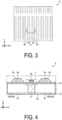
- FIG. 3 is a plan view illustrating an example of an overall configuration of the liquid discharge head according to the first embodiment.
- FIG. 4 is a cross-sectional view taken along a line IV-IV illustrated in FIG. 3 .
- FIG. 3 illustrates a three-dimensional orthogonal coordinate system including a Z axis in which a vertically upward direction is a positive direction.
- Such an orthogonal coordinate system may also be presented in other drawings used in the description below.
- a direction in which the bottom surface 8e (see FIG. 4 ) of the liquid discharge head 8 is positioned in the liquid discharge head 8, that is, a Z axis negative direction side may be referred to as "lower” or "downward”
- a Z axis positive direction side may be referred to as "upper” or "upward”.
- the liquid discharge head 8 includes a pressure chamber 20, a pressure chamber girder 21, and a piezoelectric element 30.
- the pressure chamber 20 is a hollow region having a substantially rectangular planar shape with corner portions that are rounded.
- the liquid discharge head 8 includes two or more of the pressure chambers 20 positioned such that a longitudinal direction is in a Y axis direction. Liquid is supplied into the pressure chamber 20 from a supply flow path (not illustrated).
- the pressure chamber girder 21 is positioned between the pressure chambers 20 next to each other in an X axis direction.
- the two or more pressure chambers 20 and pressure chamber girder 21 are alternately arrayed in the X axis direction to form a pressure chamber group.
- Two or more of such pressure chamber groups are arrayed in the Y axis direction. Note that two or more of the pressure chamber groups may be arrayed in the Y axis direction and the X axis direction.
- Each piezoelectric element 30 is positioned to overlap the pressure chamber 20 in a plan view.
- the piezoelectric element 30 is displaced by energization to change an internal pressure of the pressure chamber 20.
- the liquid discharge head 8 further includes a nozzle layer 22, a vibration plate 24, an individual electrode 35, and a wiring line 25.
- the nozzle layer 22 is positioned on a side of the bottom surface 8e of the liquid discharge head 8 and closes a lower end side of the pressure chamber 20.
- the nozzle layer 22 includes the nozzle 23.
- the nozzle 23 is a through hole penetrating the nozzle layer 22 in a thickness direction (a Z axis direction), and liquid supplied to an inside of the pressure chamber 20 is discharged from the nozzle 23 to an outside.
- the two or more pressure chambers 20 include a first pressure chamber 20a and a second pressure chamber 20b next to each other in the X axis direction with the pressure chamber girder 21 interposed therebetween.
- the X axis direction is an example of a first direction.
- the vibration plate 24 is positioned on the pressure chamber 20 and the pressure chamber girder 21. As illustrated in FIG. 4 , the vibration plate 24 is positioned to overlap both the first pressure chamber 20a and the second pressure chamber 20b in a plan view.
- Each individual electrode 35 is positioned to overlap the pressure chamber 20 in a plan view. Each individual electrode 35 is electrically connected to the piezoelectric element 30 corresponding thereto. The individual electrode 35 according to the embodiment is positioned on the vibration plate 24. The individual electrode 35 may be positioned side by side with the piezoelectric element 30, or may be positioned above or below the piezoelectric element 30.
- the wiring line 25 is positioned to overlap the pressure chamber girder 21 in a plan view.
- the wiring line 25 is an example of an on-girder wiring line.
- the wiring line 25 according to the embodiment is positioned on the vibration plate 24.
- the wiring line 25 is electrically connected to, for example, any one of the two or more individual electrodes 35.
- the wiring line 25 extends in the Y axis direction intersecting the X axis direction.
- FIG. 5 is an enlarged cross-sectional view of a region V indicated in FIG. 4 .
- the liquid discharge head 8 further includes an insulation layer 26.
- the insulation layer 26 is positioned to overlap the pressure chamber girder 21 in a plan view.
- the insulation layer 26 is positioned between the vibration plate 24 and the wiring line 25.
- FIG. 6 is a cross-sectional view illustrating an example of a configuration of the insulation layer included in the liquid discharge head according to the first embodiment.
- the insulation layer 26 includes a first surface 26a facing the vibration plate 24, a second surface 26b facing the wiring line 25, and a third surface 26c connecting the first surface 26a and the second surface 26b.
- a length L1 of the first surface 26a in the X axis direction is smaller than a length L2 of the second surface 26b in the X axis direction.
- the length L2 of the second surface 26b of the insulation layer 26 is larger than the length L1 of the first surface 26a, even when position shift of the wiring line 25 from a predetermined position in the X axis direction occurs, an insulation property for the wiring line 25 is easily secured.
- an angle 0 formed by the first surface 26a and the third surface 26c can be set to, for example, about 5° to 20°.
- a ratio of the length L1 of the first surface 26a to the length L2 of the second surface 26b, L1/L2 ⁇ 100, can be set to 75 (%) to 99 (%), particularly 75 (%) to 97 (%).
- the wiring line 25 includes a first end surface 25a facing the insulation layer 26 and a second end surface 25b positioned opposite to the first end surface 25a.
- a length L11 of the first end surface 25a in the X axis direction may be smaller than a length L12 of the second end surface 25b in the X axis direction.
- An increase in size of the liquid discharge head 8 due to manufacturing convenience in consideration of a possibility of position shift of the wiring line 25 from a predetermined position in the X axis direction can be reduced.
- the length L12 of the second end surface 25b of the wiring line 25 is larger than the length L11 of the first end surface 25a, a cross-sectional area of the wiring line 25 can be increased and an electrical resistance of the wiring line 25 can be reduced as compared with a case where the length L12 is equal to or less than the length L11.
- the liquid discharge head 8 may further include a protective layer 27 that covers the wiring line 25.
- the protective layer 27 may have, for example, an insulation property.
- a material of the protective layer 27 may be the same as or different from a material of the insulation layer 26.
- FIG. 6 illustrates an example of the configuration of the liquid discharge head 8, which may further include a member other than the members illustrated in FIG. 6 .
- FIG. 7 is a cross-sectional view illustrating an example of an overall configuration of a liquid discharge head according to a second embodiment.
- a length L21 of the first end surface 25a in the X axis direction may be larger than a length L22 of the second end surface 25b in the X axis direction. Accordingly, since a contact surface area between the wiring line 25 and the insulation layer 26 can be increased, for example, adhesiveness of the wiring line 25 is improved.
- FIG. 8 is a cross-sectional view illustrating an example of an overall configuration of a liquid discharge head according to a third embodiment.
- the liquid discharge head 8 illustrated in FIG. 8 includes two or more of the wiring lines 25 arranged in the X axis direction.
- the wiring lines 25 include three wiring lines 25-1 to 25-3.
- a total length L31 of lengths L31-1 to L31-3 of the first end surfaces 25a of the wiring lines 25 in the X axis direction may be smaller than a total length L32 of lengths L32-1 to L32-3 of the second end surfaces 25b of the wiring lines 25 in the X axis direction.
- the one or more wiring lines 25 are less likely to be positioned on the pressure chamber 20, and thus failure of hindering displacement of the pressure chamber 20 can be reduced.
- An increase in size of the liquid discharge head 8 due to manufacturing convenience in consideration of a possibility of position shift of the wiring line 25 from a predetermined position in the X axis direction can be reduced.
- the total length L32 of the second end surfaces 25b of the wiring lines 25 is larger than the total length L31 of the first end surfaces 25a, cross-sectional areas of the wiring lines 25 can be increased and electrical resistances of the wiring lines 25 can be reduced as compared with a case where the total length L32 is equal to or less than the total length L31.
- FIG. 8 illustrates the liquid discharge head 8 in which the three wiring lines 25 are arranged in the X axis direction, but the number of wiring lines 25 arranged in the X axis direction may be two or four or more.
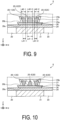
- FIG. 9 is a cross-sectional view illustrating an example of an overall configuration of a liquid discharge head according to a fourth embodiment.
- the liquid discharge head 8 illustrated in FIG. 9 includes three or more of the wiring lines 25 arranged in the X axis direction.
- the one or more wiring lines 25 are less likely to be positioned on the pressure chamber 20, and thus failure of hindering displacement of the pressure chamber 20 can be reduced.
- An increase in size of the liquid discharge head 8 due to manufacturing convenience in consideration of a possibility of position shift of the wiring line 25 from a predetermined position in the X axis direction can be reduced.
- a difference between a length L42-3 of the second end surface 25b in the X axis direction and a length 41-3 of the first end surface 25a may be smaller than a difference between the sum of the lengths of the second end surfaces 25b in the X axis direction and the sum of the lengths of the first end surfaces 25a in the wiring lines 25-1 and 25-2 positioned at both the ends in the X axis direction.
- the length L41-3 may be the same as or different from the length 42-3.
- FIG. 9 illustrates the liquid discharge head 8 in which the three wiring lines 25 are arranged in the X axis direction so that one of the wiring lines 25 is positioned in the center portion in the X axis direction, but the number of wiring lines 25 arranged in the X axis direction may be four or more. In such a case, two or more of the wiring lines 25 excluding the wiring lines 25-1 and 25-2 positioned at both the ends in the X axis direction are positioned in the center portion in the X axis direction.
- a difference between a sum of lengths of the second end surfaces 25b in the X axis direction and a sum of lengths of the first end surfaces 25a in the X axis direction may be smaller than a difference between a sum of lengths of the second end surfaces 25b in the X axis direction and a sum of lengths of the first end surfaces 25a in the X axis direction in the wiring lines 25-1 and 25-2 positioned at both ends in the X axis direction. Accordingly, cross-sectional areas of the wiring lines 25 can be ensured while ensuring a wiring pitch in a predetermined region above the insulation layer 26, and electrical resistances of the wiring lines 25 can be reduced.
- FIG. 10 is a cross-sectional view illustrating an overall configuration of a liquid discharge head according to a fifth embodiment.
- the liquid discharge head 8 according to the present embodiment is different from the liquid discharge head 8 illustrated in FIG. 8 in a cross-sectional shape of the wiring line 25-3 positioned in a center portion in the X axis direction.
- a length of the first end surface 25a in the X axis direction is smaller than a length of the second end surface 25b
- a length of the first end surface 25a in the X axis direction is larger than a length of the second end surface 25b in the wiring line 25-3.
- the one or more wiring lines 25 are less likely to be positioned on the pressure chamber 20, and thus failure of hindering displacement of the pressure chamber 20 can be reduced.
- An increase in size of the liquid discharge head 8 due to manufacturing convenience in consideration of a possibility of position shift of the wiring line 25 from a predetermined position in the X axis direction can be reduced.
- the two or more wiring lines 25 can be efficiently arranged in a predetermined region above the insulation layer 26. In this case, cross-sectional areas of the two or more wiring lines 25 may be the same. Accordingly, electrical resistances of the two or more wiring lines 25 can be made uniform, thereby improving performance of the liquid discharge head 8.
- FIG. 10 illustrates the liquid discharge head 8 in which the three wiring lines 25 are arranged in the X axis direction so that one of the wiring lines 25 is positioned in the center portion in the X axis direction, but the number of wiring lines 25 arranged in the X axis direction may be four or more.
- a length of the first end surface 25a in the X axis direction may be larger than a length of the second end surface 25b.
- the one or more wiring lines 25 are less likely to be positioned on the pressure chamber 20, and thus failure of hindering displacement of the pressure chamber 20 can be reduced.
- the two or more wiring lines 25 can be efficiently arranged in a predetermined region above the insulation layer 26.
- two or more of the wiring lines 25 positioned in the center portion in the X axis direction may be the same as each other in terms of cross-sectional area, and may be the same as the wiring lines 25 positioned at both ends in the X axis direction in terms of cross-sectional area. Accordingly, electrical resistances of the two or more wiring lines 25 can be made uniform, thereby improving performance of the liquid discharge head 8.
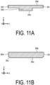
- FIG. 11A is a cross-sectional view illustrating an example of a configuration of an insulation layer included in a liquid discharge head according to a sixth embodiment.
- FIG. 11B and FIG. 11C are cross-sectional views illustrating other examples of the configuration of the insulation layer included in the liquid discharge head according to the sixth embodiment.
- the insulation layer 26 may include a first portion 261 having the same width in the X axis direction as that of the first surface 26a, and a second portion 262 having the same width in the X axis direction as that of the second surface 26b.
- the insulation layer 26 may include a fourth surface 26d extending along a YZ plane from both ends of the second surface 26b in the X axis direction, and a fifth surface 26e connecting the fourth surface 26d and the first surface 26a. Manufacturing of such an insulation layer 26 is relatively easy, for example.
- the insulation layer 26 may include a first inclined surface 26f in which a width in the X axis direction gradually decreases as viewed from the first surface 26a toward a constricted portion 26g, and a second inclined surface 26h in which a width in the X axis direction gradually increases as viewed from the constricted portion 26g toward the second surface 26b.
- a first inclined surface 26f in which a width in the X axis direction gradually decreases as viewed from the first surface 26a toward a constricted portion 26g
- a second inclined surface 26h in which a width in the X axis direction gradually increases as viewed from the constricted portion 26g toward the second surface 26b.
- the insulation layer 26 according to the present embodiment can be manufactured by appropriately combining known methods such as dry etching and a lift-off method.
- the shape of the insulation layer 26 illustrated in each of FIG. 11A to FIG. 11C may be applied to the shape of the wiring line 25.
- FIG. 12 is a cross-sectional view illustrating an example of an overall configuration of a liquid discharge head according to a seventh embodiment.
- the wiring line 25 positioned to overlap the pressure chamber girder 21 in a plan view is positioned on the vibration plate 24.
- the wiring line 25 includes the first end surface 25a facing the vibration plate 24 and the second end surface 25b positioned opposite to the first end surface 25a.
- a length L51 of the first end surface 25a in the X axis direction is smaller than a length of the second end surface 25b.
- An increase in size of the liquid discharge head 8 due to manufacturing convenience in consideration of a possibility of position shift of the wiring line 25 from a predetermined position in the X axis direction can be reduced.
- a length L52 of the second end surface 25b of the wiring line 25 is larger than the length L51 of the first end surface 25a, a cross-sectional area of the wiring line 25 can be increased and an electrical resistance of the wiring line 25 can be reduced as compared with a case where the length L52 is equal to or less than the length L51.
- FIG. 13 is a cross-sectional view illustrating an example of an overall configuration of a liquid discharge head according to an eighth embodiment.
- a length L61 of the first end surface 25a in the X axis direction may be smaller than a length L62 of the second end surface 25b in the X axis direction.
- a thickness L71 in the X axis direction of the protective layer 27 along the first end surface 25a of the wiring line 25 may be larger than a thickness L72 in the X axis direction of the protective layer 27 along the second end surface 25b.
- a length L82 in the X axis direction of an end surface 28 of the protective layer 27 positioned opposite to the first end surface 25a may be equal to or larger than a length L81 in the X axis direction of the wiring line 25 and the protective layer 27 along the first end surface 25a, the wiring line 25 being interposed between the protective layer 27.
- the wiring line 25 is less likely to be positioned on the pressure chamber 20, and thus the failure of hindering the displacement of the pressure chamber 20 can be reduced.
- An increase in size of the liquid discharge head 8 due to manufacturing convenience in consideration of a possibility of position shift of the wiring line 25 from a predetermined position in the X axis direction can be reduced.
- the thickness L71 in the X axis direction of the protective layer 27 along the first end surface 25a larger than the thickness L72 in the X axis direction of the protective layer 27 along the second end surface 25b, for example, even when dew condensation or the like occurs in a vicinity of an interface between the vibration plate 24 and the protective layer 27, water resistance protection performance against water droplets that are likely to remain in an acute angle portion can be increased, and reliability can be further improved.
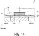
- FIG. 14 is a cross-sectional view illustrating an overall configuration of a liquid discharge head according to a ninth embodiment.
- a distance to an end portion 25a1 of the first end surface 25a facing the vibration plate 24 on a side of the first pressure chamber 20a is a radius r, and the wiring line 25 need not be positioned within a virtual circle VC when viewed in cross-section along the virtual circle VC with the opening end 29 as a center.
- the wiring line 25 is less likely to be positioned on the pressure chamber 20, and thus the failure of hindering the displacement of the pressure chamber 20 can be reduced.
- An increase in size of the liquid discharge head 8 due to manufacturing convenience in consideration of a possibility of position shift of the wiring line 25 from a predetermined position in the X axis direction can be reduced. Failure such as aggregation of a liquid positioned inside the pressure chamber 20 due to an electric field generated by energization of the wiring line 25 can be made less likely to occur, and reliability of the liquid discharge head 8 can be improved.
- FIG. 14 illustrates the example in which the wiring line 25 is positioned on the vibration plate 24, the present disclosure can also be applied to a case in which the wiring line 25 is positioned on the insulation layer 26 as illustrated in FIG. 5 .
- the pressure chambers 20 including the first pressure chamber 20a and the second pressure chamber 20b next to each other in the X axis direction, and the pressure chamber girder 21 positioned between the first pressure chamber 20a and the second pressure chamber 20b are formed.
- the vibration plate 24 is positioned to overlap both the first pressure chamber 20a and the second pressure chamber 20b in a plan view.
- Two or more of the individual electrodes 35 are positioned respectively to overlap the two or more pressure chambers 20 in a plan view.
- Two or more wiring lines are electrically connected to the two or more individual electrodes 35, respectively.
- the insulation layer 26 is positioned between the vibration plate 24 and the wiring line 25 positioned to overlap the pressure chamber girder 21 in a plan view among the two or more wiring lines.
- the insulation layer 26 is prepared that includes the first surface 26a facing the vibration plate 24 and the second surface 26b facing the wiring line 25 and in which a length of the first surface 26a in the X axis direction is smaller than a length of the second surface 26b, and the insulation layer 26 is positioned to overlap the pressure chamber girder 21 in a plan view.
- the liquid discharge head 8 according to the present embodiment is obtained.
- the wiring line 25 that includes the first end surface 25a facing the vibration plate 24 and the second end surface 25b positioned opposite to the first end surface 25a and in which a length of the first end surface 25a in the X axis direction is smaller than a length of the second end surface 25b is positioned to overlap the pressure chamber girder 21 in a plan view.
- liquid discharge head 8 according to another embodiment can be manufactured as the same as and/or similar to the liquid discharge head 8 according to each of the above-described embodiments.
- the manufacturing method for the liquid discharge head 8 according to each of the embodiments described above is merely an example, and there is no limitation on, for example, the order of the respective processes.
- the liquid discharge head 8 includes the two or more pressure chambers 20, the pressure chamber girder 21, the vibration plate 24, the two or more individual electrodes 35, the two or more wiring lines, and the insulation layer 26.
- the two or more pressure chambers 20 include the first pressure chamber 20a and the second pressure chamber 20b next to each other in the first direction.
- the pressure chamber girder 21 is positioned between the first pressure chamber 20a and the second pressure chamber 20b.
- the vibration plate 24 is positioned to overlap both the first pressure chamber 20a and the second pressure chamber 20b in a plan view.
- the two or more individual electrodes 35 are positioned respectively to overlap the two or more pressure chambers 20 in a plan view.
- the two or more wiring lines are electrically connected to the two or more individual electrodes 35, respectively.
- the insulation layer 26 is positioned between the vibration plate 24 and the on-girder wiring line (wiring line 25) positioned to overlap the pressure chamber girder 21 in a plan view among the two or more wiring lines.
- the insulation layer 26 includes the first surface 26a facing the vibration plate 24 and the second surface 26b facing the on-girder wiring line (wiring line 25), and is positioned to overlap the pressure chamber girder 21 in a plan view.
- the length of the first surface 26a in the first direction is smaller than the length of the second surface 26b in the first direction.
- the liquid discharge head 8 includes the two or more pressure chambers 20, the pressure chamber girder 21, the vibration plate 24, the two or more individual electrodes 35, and the two or more wiring lines.
- the two or more pressure chambers 20 include the first pressure chamber 20a and the second pressure chamber 20b next to each other in the first direction.
- the pressure chamber girder 21 is positioned between the first pressure chamber 20a and the second pressure chamber 20b.
- the vibration plate 24 is positioned to overlap both the first pressure chamber 20a and the second pressure chamber 20b in a plan view.
- the two or more individual electrodes 35 are positioned respectively to overlap the two or more pressure chambers 20 in a plan view.
- the two or more wiring lines are electrically connected to the two or more individual electrodes 35, respectively.
- the on-girder wiring line (wiring line 25) positioned to overlap the pressure chamber girder 21 in a plan view among the two or more wiring lines includes the first end surface 25a facing the vibration plate 24 and the second end surface 25b positioned opposite to the first end surface 25a.
- the length of the first end surface 25a in the first direction is smaller than the length of the second end surface 25b in the first direction.
Landscapes
- Engineering & Computer Science (AREA)
- Manufacturing & Machinery (AREA)
- Particle Formation And Scattering Control In Inkjet Printers (AREA)
Abstract
Description
- The disclosed embodiments relate to a liquid discharge head, a recording device, and a manufacturing method for a liquid discharge head.
- Inkjet printers and inkjet plotters utilizing an inkjet recording method are known examples of printing apparatuses. A liquid discharge head for discharging liquid is mounted in such a printing apparatus using an inkjet method.
- In such a liquid discharge head, for example, a wiring line drawn out from an individual electrode provided in a piezoelectric element for discharging liquid is disposed on a pressure chamber girder positioned between adjacent pressure chambers, thereby achieving miniaturization.
- Patent Document 1:
JP 2017-132170 A - In an aspect of an embodiment, a liquid discharge head includes two or more pressure chambers, a pressure chamber girder, a vibration plate, two or more individual electrodes, two or more wiring lines, and an insulation layer. The two or more pressure chambers include a first pressure chamber and a second pressure chamber next to each other in a first direction. The pressure chamber girder is positioned between the first pressure chamber and the second pressure chamber. The vibration plate is positioned to overlap both the first pressure chamber and the second pressure chamber in a plan view. The two or more individual electrodes are positioned respectively to overlap the two or more pressure chambers in the plan view. The two or more wiring lines are electrically connected to the two or more individual electrodes, respectively. The insulation layer is positioned between the vibration plate and an on-girder wiring line positioned to overlap the pressure chamber girder in the plan view among the two or more wiring lines. The insulation layer includes a first surface facing the vibration plate and a second surface facing the on-girder wiring line, and is positioned to overlap the pressure chamber girder in the plan view. A length of the first surface in the first direction is smaller than a length of the second surface in the first direction.
-
-
FIG. 1 is a front view schematically illustrating an overall front of a printer according to an embodiment. -
FIG. 2 is a plan view schematically illustrating an overall plan of the printer according to the embodiment. -
FIG. 3 is a plan view illustrating an example of an overall configuration of a liquid discharge head according to a first embodiment. -
FIG. 4 is a cross-sectional view taken along a line IV-IV illustrated inFIG. 3 . -
FIG. 5 is an enlarged cross-sectional view of a region V illustrated inFIG. 4 . -
FIG. 6 is a cross-sectional view illustrating an example of a configuration of an insulation layer included in the liquid discharge head according to the first embodiment. -
FIG. 7 is a cross-sectional view illustrating an example of an overall configuration of a liquid discharge head according to a second embodiment. -
FIG. 8 is a cross-sectional view illustrating an example of an overall configuration of a liquid discharge head according to a third embodiment. -
FIG. 9 is a cross-sectional view illustrating an example of an overall configuration of a liquid discharge head according to a fourth embodiment. -
FIG. 10 is a cross-sectional view illustrating an example of an overall configuration of a liquid discharge head according to a fifth embodiment. -
FIG. 11A is a cross-sectional view illustrating an example of a configuration of an insulation layer included in a liquid discharge head according to a sixth embodiment. -
FIG. 11B is a cross-sectional view illustrating another example of the configuration of the insulation layer included in the liquid discharge head according to the sixth embodiment. -
FIG. 11C is a cross-sectional view illustrating a still another example of the configuration of the insulation layer included in the liquid discharge head according to the sixth embodiment. -
FIG. 12 is a cross-sectional view illustrating an example of an overall configuration of a liquid discharge head according to a seventh embodiment. -
FIG. 13 is a cross-sectional view illustrating an example of an overall configuration of a liquid discharge head according to an eighth embodiment. -
FIG. 14 is a cross-sectional view illustrating an example of an overall configuration of a liquid discharge head according to a ninth embodiment. - In the above-described liquid discharge head, since tolerance for position shift in a manufacturing process is small, there is room for further improvement in terms of achieving miniaturization.
- Therefore, provision of a liquid discharge head in which failure caused by position shift can be reduced, a recording device, and a manufacturing method for a liquid discharge head is expected.
- Embodiments of a liquid discharge head, a recording device, and a manufacturing method for a liquid discharge head disclosed in the present application will be described below with reference to the accompanying drawings. The present disclosure is not limited by the following embodiments. Note that the drawings are schematic and that the dimensional relationships between elements, the proportions of the elements, and the like may differ from the actual ones. There may be differences between the drawings in terms of dimensional relationships, proportions, and the like.
- In the embodiments described below, expressions such as "constant", "orthogonal", "perpendicular", and "parallel" may be used, but these expressions do not mean strictly "constant", "orthogonal", "perpendicular", and "parallel". In other words, it is assumed that the above expressions allow for deviations in manufacturing accuracy, installation accuracy, or the like.
- Embodiments can be appropriately combined so as not to contradict each other in terms of processing content. In the following embodiments, the same portions are denoted by the same reference signs, and redundant explanations are omitted.
- First, with reference to
FIG. 1 and FIG. 2 , a description will be given of an overview of a printer serving as an example of a recording device according to an embodiment.FIG. 1 is a front view schematically illustrating an overall front of the printer according to the embodiment.FIG. 2 is a plan view schematically illustrating an overall plan of the printer according to the embodiment. The printer according to the embodiment is, for example, a color inkjet printer. - As illustrated in
FIG. 1 , aprinter 1 includes apaper feed roller 2,guide rollers 3, anapplicator 4, ahead case 5, two ormore transport rollers 6, two ormore frames 7, two or moreliquid discharge heads 8,transport rollers 9, adryer 10,transport rollers 11, asensor 12, and acollection roller 13. Thetransport roller 6 is an example of a transporter. - The
printer 1 further includes acontroller 14 configured to control each part of theprinter 1. Thecontroller 14 controls operation of thepaper feed roller 2, theguide rollers 3, theapplicator 4, thehead case 5, the two ormore transport rollers 6, the two ormore frames 7, the two or moreliquid discharge heads 8, thetransport rollers 9, thedryer 10, thetransport rollers 11, thesensor 12, and thecollection roller 13. - By landing droplets on a printing sheet P, the
printer 1 records images and characters on the printing sheet P. The printing sheet P is an example of a recording medium. The printing sheet P is rolled on thepaper feed roller 2 prior to use. Theprinter 1 conveys the printing sheet P from thepaper feed roller 2 to an inside of thehead case 5 via theguide rollers 3 and theapplicator 4. - The
applicator 4 uniformly applies a coating agent over the printing sheet P. This can perform surface treatment on the printing sheet P, improving printing quality of theprinter 1. - The
head case 5 houses the two ormore transport rollers 6, the two ormore frames 7, and the two or more liquid discharge heads 8. The inside of thehead case 5 is formed with a space separated from an outside except for a part connected to the outside such as parts where the printing sheet P enters and exits. - As required, the
controller 14 controls at least one of controllable factors of the inside space of thehead case 5, such as temperature, humidity, and air pressure. Thetransport rollers 6 convey the printing sheet P near the liquid discharge heads 8 inside thehead case 5. - The
frames 7 are rectangular flat plates and are positioned above and close to the printing sheet P to be conveyed by thetransport rollers 6. As illustrated inFIG. 2 , theframes 7 are positioned having a longitudinal direction orthogonal to a conveyance direction of the printing sheet P. Inside thehead case 5, the two or more (e.g., four)frames 7 are positioned at predetermined intervals along the conveyance direction of the printing sheet P. - Liquid, for example, ink, is supplied to the liquid discharge heads 8 from a liquid tank (not illustrated). The liquid discharge heads 8 discharge the liquid supplied from the liquid tank.
- The
controller 14 controls the liquid discharge heads 8 based on data of an image, characters, or the like to discharge the liquid toward the printing sheet P. A distance between eachliquid discharge head 8 and the printing sheet P is, for example, approximately 0.5 mm to 20 mm. - Each of the liquid discharge heads 8 is fixed to the
frame 7. The liquid discharge heads 8 are positioned having the longitudinal direction orthogonal to the conveyance direction of the printing sheet P. - That is, the
printer 1 according to the present embodiment is a so-called line printer in which the liquid discharge heads 8 are fixed inside theprinter 1. Note that, theprinter 1 according to the present embodiment is not limited to a line printer and may also be a so-called serial printer. - The serial printer is a printer employing a method of alternately performing operations of recording while moving the liquid discharge heads 8 in a manner such as reciprocation in a direction intersecting (e.g., substantially orthogonal to) the conveyance direction of the printing sheet P, and conveying the printing sheet P.
- As illustrated in
FIG. 2 , the two or more (e.g., five) liquid discharge heads 8 are fixed to one of theframes 7.FIG. 2 illustrates an example in which three of the liquid discharge heads 8 are positioned on a forward side and two of the liquid discharge heads 8 are positioned on a rearward side, in the conveyance direction of the printing sheet P. Further, the liquid discharge heads 8 are positioned without their centers overlapping in the conveyance direction of the printing sheet P. - The two or more liquid discharge heads 8 positioned in one of the
frames 7 form ahead group 8A. Four of thehead groups 8A are positioned along the conveyance direction of the printing sheet P. The liquid discharge heads 8 belonging to thesame head group 8A are supplied with ink of four colors. As a result, theprinter 1 can perform printing with the four colors of ink using the fourhead groups 8A. - The colors of the ink discharged from the respective liquid discharge heads 8 are, for example, magenta (M), yellow (Y), cyan (C), and black (K). The
controller 14 can print a color image on the printing sheet P by controlling the respective liquid discharge heads 8 to discharge the two or more colors of ink onto the printing sheet P. - Note that surface treatment may be performed on the printing sheet P, by discharging a coating agent from the
liquid discharge head 8 onto the printing sheet P. - The number of liquid discharge heads 8 included in one of the
head groups 8A and the number ofhead groups 8A mounted in theprinter 1 can be changed as appropriate in accordance with printing targets and printing conditions. For example, when printing is performed in a printable range with a singleliquid discharge head 8, only a singleliquid discharge head 8 may be provided in theprinter 1. - The printing sheet P printed inside the
head case 5 is conveyed to the outside of thehead case 5 by thetransport rollers 9 and passes through the inside of thedryer 10. Thedryer 10 dries the printing sheet P printed. The printing sheet P dried by thedryer 10 is conveyed by thetransport rollers 11 and then collected by thecollection roller 13. - In the
printer 1, by drying the printing sheet P with thedryer 10, bonding, or rubbing of an undried liquid, between the printing sheets P overlapped with each other and rolled at thecollection roller 13 can be suppressed. - The
sensor 12 includes a position sensor, a speed sensor, a temperature sensor, or the like. Based on information from thesensor 12, thecontroller 14 can determine a state of each part of theprinter 1 and control each part of theprinter 1. - In the
printer 1 described above, the printing sheet P is the printing target (i.e., the recording medium), but the printing target in theprinter 1 is not limited to the printing sheet P, and a roll type fabric or the like may be the printing target. - The
printer 1 may convey the printing sheet P put on a conveyor belt instead of directly conveying the printing sheet P. By using the conveyor belt, theprinter 1 can perform printing on a sheet of paper, a cut cloth, wood, a tile, or the like as a printing target. - The
printer 1 may discharge a liquid containing electrically conductive particles from the liquid discharge heads 8, to print a wiring pattern or the like of an electronic device. Theprinter 1 may discharge a liquid containing a predetermined amount of a liquid chemical agent or a liquid containing the chemical agent from the liquid discharge heads 8 onto a reaction vessel or the like to produce chemicals. - The
printer 1 may also include a cleaner for cleaning the liquid discharge heads 8. The cleaner cleans the liquid discharge heads 8 by, for example, a wiping process or a capping process. - The wiping process is, for example, a process of wiping a surface of a portion from which liquid is discharged using a flexible wiper, thereby removing the liquid attached to the
liquid discharge head 8. - The capping process is performed as follows, for example. First, a cap is put to cover a portion to which liquid is discharged, for example, a
bottom surface 8e (seeFIG. 4 ) of the liquid discharge head 8 (this is called capping). As a result, a substantially sealed space is formed between thebottom surface 8e and the cap. - The discharge of liquid is then repeated in such a hermetically sealed space. Consequently, a liquid having a viscosity higher than that in a normal state, foreign matter, or the like that has clogged a nozzle 23 (see
FIG. 4 ) can be removed. - Next, a configuration of the
liquid discharge head 8 according to a first embodiment will be described with reference toFIG. 3 to FIG. 5 .FIG. 3 is a plan view illustrating an example of an overall configuration of the liquid discharge head according to the first embodiment.FIG. 4 is a cross-sectional view taken along a line IV-IV illustrated inFIG. 3 . - Note that, for the sake of clarity,
FIG. 3 illustrates a three-dimensional orthogonal coordinate system including a Z axis in which a vertically upward direction is a positive direction. Such an orthogonal coordinate system may also be presented in other drawings used in the description below. In the following description, for convenience, a direction in which thebottom surface 8e (seeFIG. 4 ) of theliquid discharge head 8 is positioned in theliquid discharge head 8, that is, a Z axis negative direction side may be referred to as "lower" or "downward", and a Z axis positive direction side may be referred to as "upper" or "upward". - As illustrated in
FIG. 3 , theliquid discharge head 8 includes apressure chamber 20, apressure chamber girder 21, and apiezoelectric element 30. Thepressure chamber 20 is a hollow region having a substantially rectangular planar shape with corner portions that are rounded. As illustrated inFIG. 3 , theliquid discharge head 8 includes two or more of thepressure chambers 20 positioned such that a longitudinal direction is in a Y axis direction. Liquid is supplied into thepressure chamber 20 from a supply flow path (not illustrated). - The
pressure chamber girder 21 is positioned between thepressure chambers 20 next to each other in an X axis direction. The two ormore pressure chambers 20 andpressure chamber girder 21 are alternately arrayed in the X axis direction to form a pressure chamber group. Two or more of such pressure chamber groups are arrayed in the Y axis direction. Note that two or more of the pressure chamber groups may be arrayed in the Y axis direction and the X axis direction. - Each
piezoelectric element 30 is positioned to overlap thepressure chamber 20 in a plan view. Thepiezoelectric element 30 is displaced by energization to change an internal pressure of thepressure chamber 20. - As illustrated in
FIG. 4 , theliquid discharge head 8 further includes anozzle layer 22, avibration plate 24, anindividual electrode 35, and awiring line 25. - The
nozzle layer 22 is positioned on a side of thebottom surface 8e of theliquid discharge head 8 and closes a lower end side of thepressure chamber 20. Thenozzle layer 22 includes thenozzle 23. Thenozzle 23 is a through hole penetrating thenozzle layer 22 in a thickness direction (a Z axis direction), and liquid supplied to an inside of thepressure chamber 20 is discharged from thenozzle 23 to an outside. - The two or
more pressure chambers 20 include afirst pressure chamber 20a and asecond pressure chamber 20b next to each other in the X axis direction with thepressure chamber girder 21 interposed therebetween. The X axis direction is an example of a first direction. - The
vibration plate 24 is positioned on thepressure chamber 20 and thepressure chamber girder 21. As illustrated inFIG. 4 , thevibration plate 24 is positioned to overlap both thefirst pressure chamber 20a and thesecond pressure chamber 20b in a plan view. - Each
individual electrode 35 is positioned to overlap thepressure chamber 20 in a plan view. Eachindividual electrode 35 is electrically connected to thepiezoelectric element 30 corresponding thereto. Theindividual electrode 35 according to the embodiment is positioned on thevibration plate 24. Theindividual electrode 35 may be positioned side by side with thepiezoelectric element 30, or may be positioned above or below thepiezoelectric element 30. - The
wiring line 25 is positioned to overlap thepressure chamber girder 21 in a plan view. Thewiring line 25 is an example of an on-girder wiring line. Thewiring line 25 according to the embodiment is positioned on thevibration plate 24. Thewiring line 25 is electrically connected to, for example, any one of the two or moreindividual electrodes 35. Thewiring line 25 extends in the Y axis direction intersecting the X axis direction. - Next, a configuration of the
wiring line 25 according to the present embodiment and a vicinity thereof will be further described with reference toFIG 5. FIG. 5 is an enlarged cross-sectional view of a region V indicated inFIG. 4 . - As illustrated in
FIG. 5 , theliquid discharge head 8 further includes aninsulation layer 26. Theinsulation layer 26 is positioned to overlap thepressure chamber girder 21 in a plan view. Theinsulation layer 26 is positioned between thevibration plate 24 and thewiring line 25. - Here, the
insulation layer 26 will be further described in detail usingFIG. 5 and FIG. 6. FIG. 6 is a cross-sectional view illustrating an example of a configuration of the insulation layer included in the liquid discharge head according to the first embodiment. - The
insulation layer 26 includes afirst surface 26a facing thevibration plate 24, asecond surface 26b facing thewiring line 25, and athird surface 26c connecting thefirst surface 26a and thesecond surface 26b. A length L1 of thefirst surface 26a in the X axis direction is smaller than a length L2 of thesecond surface 26b in the X axis direction. As a result, theinsulation layer 26 is less likely to be positioned on thepressure chamber 20, and thus failure of hindering displacement of thepressure chamber 20 can be reduced. An increase in size of theliquid discharge head 8 due to manufacturing convenience in consideration of a possibility of position shift of theinsulation layer 26 from a predetermined position in the X axis direction can be reduced. - Since the length L2 of the
second surface 26b of theinsulation layer 26 is larger than the length L1 of thefirst surface 26a, even when position shift of thewiring line 25 from a predetermined position in the X axis direction occurs, an insulation property for thewiring line 25 is easily secured. - As illustrated in
FIG. 6 , an angle 0 formed by thefirst surface 26a and thethird surface 26c can be set to, for example, about 5° to 20°. A ratio of the length L1 of thefirst surface 26a to the length L2 of thesecond surface 26b, L1/L2 × 100, can be set to 75 (%) to 99 (%), particularly 75 (%) to 97 (%). - Returning to
FIG. 5 , thewiring line 25 includes afirst end surface 25a facing theinsulation layer 26 and asecond end surface 25b positioned opposite to thefirst end surface 25a. A length L11 of thefirst end surface 25a in the X axis direction may be smaller than a length L12 of thesecond end surface 25b in the X axis direction. As a result, thewiring line 25 is less likely to be positioned on thepressure chamber 20, and thus the failure of hindering the displacement of thepressure chamber 20 can be reduced. An increase in size of theliquid discharge head 8 due to manufacturing convenience in consideration of a possibility of position shift of thewiring line 25 from a predetermined position in the X axis direction can be reduced. - Since the length L12 of the
second end surface 25b of thewiring line 25 is larger than the length L11 of thefirst end surface 25a, a cross-sectional area of thewiring line 25 can be increased and an electrical resistance of thewiring line 25 can be reduced as compared with a case where the length L12 is equal to or less than the length L11. - The
liquid discharge head 8 may further include aprotective layer 27 that covers thewiring line 25. As a result, durability of thewiring line 25 can be enhanced. Theprotective layer 27 may have, for example, an insulation property. A material of theprotective layer 27 may be the same as or different from a material of theinsulation layer 26. - Note that
FIG. 6 illustrates an example of the configuration of theliquid discharge head 8, which may further include a member other than the members illustrated inFIG. 6 . -
FIG. 7 is a cross-sectional view illustrating an example of an overall configuration of a liquid discharge head according to a second embodiment. As illustrated inFIG. 7 , in thewiring line 25, a length L21 of thefirst end surface 25a in the X axis direction may be larger than a length L22 of thesecond end surface 25b in the X axis direction. Accordingly, since a contact surface area between thewiring line 25 and theinsulation layer 26 can be increased, for example, adhesiveness of thewiring line 25 is improved. -
FIG. 8 is a cross-sectional view illustrating an example of an overall configuration of a liquid discharge head according to a third embodiment. Theliquid discharge head 8 illustrated inFIG. 8 includes two or more of thewiring lines 25 arranged in the X axis direction. The wiring lines 25 include three wiring lines 25-1 to 25-3. A total length L31 of lengths L31-1 to L31-3 of the first end surfaces 25a of thewiring lines 25 in the X axis direction may be smaller than a total length L32 of lengths L32-1 to L32-3 of the second end surfaces 25b of thewiring lines 25 in the X axis direction. As a result, the one ormore wiring lines 25 are less likely to be positioned on thepressure chamber 20, and thus failure of hindering displacement of thepressure chamber 20 can be reduced. An increase in size of theliquid discharge head 8 due to manufacturing convenience in consideration of a possibility of position shift of thewiring line 25 from a predetermined position in the X axis direction can be reduced. - Since the total length L32 of the second end surfaces 25b of the wiring lines 25 is larger than the total length L31 of the
first end surfaces 25a, cross-sectional areas of thewiring lines 25 can be increased and electrical resistances of thewiring lines 25 can be reduced as compared with a case where the total length L32 is equal to or less than the total length L31. -
FIG. 8 illustrates theliquid discharge head 8 in which the threewiring lines 25 are arranged in the X axis direction, but the number ofwiring lines 25 arranged in the X axis direction may be two or four or more. -
FIG. 9 is a cross-sectional view illustrating an example of an overall configuration of a liquid discharge head according to a fourth embodiment. Theliquid discharge head 8 illustrated inFIG. 9 includes three or more of thewiring lines 25 arranged in the X axis direction. In thewiring lines 25 positioned at both ends in the X axis direction among the three ormore wiring lines 25 arranged in the X axis direction, that is, the wiring lines 25-1 and 25-2, a sum of lengths of thefirst end surfaces 25a in the X axis direction (= a length (L41-1) + a length (41-2)) may be smaller than a sum of lengths of the second end surfaces 25b in the X axis direction (= a length (L42-1) + a length (42-2)). As a result, the one ormore wiring lines 25 are less likely to be positioned on thepressure chamber 20, and thus failure of hindering displacement of thepressure chamber 20 can be reduced. An increase in size of theliquid discharge head 8 due to manufacturing convenience in consideration of a possibility of position shift of thewiring line 25 from a predetermined position in the X axis direction can be reduced. - In the wiring line 25-3, which is the
wiring line 25 positioned in a center portion in the X axis direction among the three ormore wiring lines 25 arranged in the X axis direction, a difference between a length L42-3 of thesecond end surface 25b in the X axis direction and a length 41-3 of thefirst end surface 25a may be smaller than a difference between the sum of the lengths of the second end surfaces 25b in the X axis direction and the sum of the lengths of thefirst end surfaces 25a in the wiring lines 25-1 and 25-2 positioned at both the ends in the X axis direction. Accordingly, cross-sectional areas of thewiring lines 25 can be ensured while ensuring a wiring pitch in a predetermined region above theinsulation layer 26, and electrical resistances of thewiring lines 25 can be reduced. In this case, the length L41-3 may be the same as or different from the length 42-3. -
FIG. 9 illustrates theliquid discharge head 8 in which the threewiring lines 25 are arranged in the X axis direction so that one of the wiring lines 25 is positioned in the center portion in the X axis direction, but the number ofwiring lines 25 arranged in the X axis direction may be four or more. In such a case, two or more of thewiring lines 25 excluding the wiring lines 25-1 and 25-2 positioned at both the ends in the X axis direction are positioned in the center portion in the X axis direction. In this case, in two or more on-girder wiring lines positioned in the center portion in the X axis direction, a difference between a sum of lengths of the second end surfaces 25b in the X axis direction and a sum of lengths of thefirst end surfaces 25a in the X axis direction may be smaller than a difference between a sum of lengths of the second end surfaces 25b in the X axis direction and a sum of lengths of thefirst end surfaces 25a in the X axis direction in the wiring lines 25-1 and 25-2 positioned at both ends in the X axis direction. Accordingly, cross-sectional areas of thewiring lines 25 can be ensured while ensuring a wiring pitch in a predetermined region above theinsulation layer 26, and electrical resistances of thewiring lines 25 can be reduced. -
FIG. 10 is a cross-sectional view illustrating an overall configuration of a liquid discharge head according to a fifth embodiment. As illustrated inFIG. 10 , theliquid discharge head 8 according to the present embodiment is different from theliquid discharge head 8 illustrated inFIG. 8 in a cross-sectional shape of the wiring line 25-3 positioned in a center portion in the X axis direction. To be more specific, in each of the wiring lines 25-1 and 25-2, a length of thefirst end surface 25a in the X axis direction is smaller than a length of thesecond end surface 25b, on the other hand, a length of thefirst end surface 25a in the X axis direction is larger than a length of thesecond end surface 25b in the wiring line 25-3. As a result, the one ormore wiring lines 25 are less likely to be positioned on thepressure chamber 20, and thus failure of hindering displacement of thepressure chamber 20 can be reduced. An increase in size of theliquid discharge head 8 due to manufacturing convenience in consideration of a possibility of position shift of thewiring line 25 from a predetermined position in the X axis direction can be reduced. The two ormore wiring lines 25 can be efficiently arranged in a predetermined region above theinsulation layer 26. In this case, cross-sectional areas of the two ormore wiring lines 25 may be the same. Accordingly, electrical resistances of the two ormore wiring lines 25 can be made uniform, thereby improving performance of theliquid discharge head 8. -
FIG. 10 illustrates theliquid discharge head 8 in which the threewiring lines 25 are arranged in the X axis direction so that one of the wiring lines 25 is positioned in the center portion in the X axis direction, but the number ofwiring lines 25 arranged in the X axis direction may be four or more. In such a case, for one or more of thewiring lines 25 positioned in the center portion in the X axis direction, a length of thefirst end surface 25a in the X axis direction may be larger than a length of thesecond end surface 25b. As a result, the one ormore wiring lines 25 are less likely to be positioned on thepressure chamber 20, and thus failure of hindering displacement of thepressure chamber 20 can be reduced. An increase in size of theliquid discharge head 8 due to manufacturing convenience in consideration of a possibility of position shift of thewiring line 25 from a predetermined position in the X axis direction can be reduced. The two ormore wiring lines 25 can be efficiently arranged in a predetermined region above theinsulation layer 26. At this time, two or more of thewiring lines 25 positioned in the center portion in the X axis direction may be the same as each other in terms of cross-sectional area, and may be the same as thewiring lines 25 positioned at both ends in the X axis direction in terms of cross-sectional area. Accordingly, electrical resistances of the two ormore wiring lines 25 can be made uniform, thereby improving performance of theliquid discharge head 8. -
FIG. 11A is a cross-sectional view illustrating an example of a configuration of an insulation layer included in a liquid discharge head according to a sixth embodiment.FIG. 11B andFIG. 11C are cross-sectional views illustrating other examples of the configuration of the insulation layer included in the liquid discharge head according to the sixth embodiment. - As illustrated in
FIG. 11A , theinsulation layer 26 may include afirst portion 261 having the same width in the X axis direction as that of thefirst surface 26a, and a second portion 262 having the same width in the X axis direction as that of thesecond surface 26b. - As illustrated in
FIG. 11B , theinsulation layer 26 may include afourth surface 26d extending along a YZ plane from both ends of thesecond surface 26b in the X axis direction, and afifth surface 26e connecting thefourth surface 26d and thefirst surface 26a. Manufacturing of such aninsulation layer 26 is relatively easy, for example. - As illustrated in
FIG. 11C , theinsulation layer 26 may include a firstinclined surface 26f in which a width in the X axis direction gradually decreases as viewed from thefirst surface 26a toward aconstricted portion 26g, and a secondinclined surface 26h in which a width in the X axis direction gradually increases as viewed from theconstricted portion 26g toward thesecond surface 26b. According tosuch insulation layer 26, for example, even when dew condensation occurs on a surface of theinsulation layer 26, theinsulation layer 26 is easily dried, and durability is improved. - Note that, the
insulation layer 26 according to the present embodiment can be manufactured by appropriately combining known methods such as dry etching and a lift-off method. For example, the shape of theinsulation layer 26 illustrated in each ofFIG. 11A to FIG. 11C may be applied to the shape of thewiring line 25. -
FIG. 12 is a cross-sectional view illustrating an example of an overall configuration of a liquid discharge head according to a seventh embodiment. In theliquid discharge head 8 illustrated inFIG. 12 , thewiring line 25 positioned to overlap thepressure chamber girder 21 in a plan view is positioned on thevibration plate 24. Thewiring line 25 includes thefirst end surface 25a facing thevibration plate 24 and thesecond end surface 25b positioned opposite to thefirst end surface 25a. A length L51 of thefirst end surface 25a in the X axis direction is smaller than a length of thesecond end surface 25b. As a result, thewiring line 25 is less likely to be positioned on thepressure chamber 20, and thus the failure of hindering the displacement of thepressure chamber 20 can be reduced. An increase in size of theliquid discharge head 8 due to manufacturing convenience in consideration of a possibility of position shift of thewiring line 25 from a predetermined position in the X axis direction can be reduced. - Since a length L52 of the
second end surface 25b of thewiring line 25 is larger than the length L51 of thefirst end surface 25a, a cross-sectional area of thewiring line 25 can be increased and an electrical resistance of thewiring line 25 can be reduced as compared with a case where the length L52 is equal to or less than the length L51. -
FIG. 13 is a cross-sectional view illustrating an example of an overall configuration of a liquid discharge head according to an eighth embodiment. As illustrated inFIG. 13 , in theliquid discharge head 8, a length L61 of thefirst end surface 25a in the X axis direction may be smaller than a length L62 of thesecond end surface 25b in the X axis direction. A thickness L71 in the X axis direction of theprotective layer 27 along thefirst end surface 25a of thewiring line 25 may be larger than a thickness L72 in the X axis direction of theprotective layer 27 along thesecond end surface 25b. A length L82 in the X axis direction of anend surface 28 of theprotective layer 27 positioned opposite to thefirst end surface 25a may be equal to or larger than a length L81 in the X axis direction of thewiring line 25 and theprotective layer 27 along thefirst end surface 25a, thewiring line 25 being interposed between theprotective layer 27. As a result, thewiring line 25 is less likely to be positioned on thepressure chamber 20, and thus the failure of hindering the displacement of thepressure chamber 20 can be reduced. An increase in size of theliquid discharge head 8 due to manufacturing convenience in consideration of a possibility of position shift of thewiring line 25 from a predetermined position in the X axis direction can be reduced. - By making the thickness L71 in the X axis direction of the
protective layer 27 along thefirst end surface 25a larger than the thickness L72 in the X axis direction of theprotective layer 27 along thesecond end surface 25b, for example, even when dew condensation or the like occurs in a vicinity of an interface between thevibration plate 24 and theprotective layer 27, water resistance protection performance against water droplets that are likely to remain in an acute angle portion can be increased, and reliability can be further improved. -
FIG. 14 is a cross-sectional view illustrating an overall configuration of a liquid discharge head according to a ninth embodiment. As illustrated inFIG. 14 , in theliquid discharge head 8, between thewiring line 25 and an openingend 29 of thefirst pressure chamber 20a on a side of thepressure chamber girder 21, a distance to an end portion 25a1 of thefirst end surface 25a facing thevibration plate 24 on a side of thefirst pressure chamber 20a is a radius r, and thewiring line 25 need not be positioned within a virtual circle VC when viewed in cross-section along the virtual circle VC with the openingend 29 as a center. As a result, thewiring line 25 is less likely to be positioned on thepressure chamber 20, and thus the failure of hindering the displacement of thepressure chamber 20 can be reduced. An increase in size of theliquid discharge head 8 due to manufacturing convenience in consideration of a possibility of position shift of thewiring line 25 from a predetermined position in the X axis direction can be reduced. Failure such as aggregation of a liquid positioned inside thepressure chamber 20 due to an electric field generated by energization of thewiring line 25 can be made less likely to occur, and reliability of theliquid discharge head 8 can be improved. - Note that, although
FIG. 14 illustrates the example in which thewiring line 25 is positioned on thevibration plate 24, the present disclosure can also be applied to a case in which thewiring line 25 is positioned on theinsulation layer 26 as illustrated inFIG. 5 . - Next, an example of a manufacturing method for the
liquid discharge head 8 according to the first embodiment will be described. First, two or more of thepressure chambers 20 including thefirst pressure chamber 20a and thesecond pressure chamber 20b next to each other in the X axis direction, and thepressure chamber girder 21 positioned between thefirst pressure chamber 20a and thesecond pressure chamber 20b are formed. Next, thevibration plate 24 is positioned to overlap both thefirst pressure chamber 20a and thesecond pressure chamber 20b in a plan view. Two or more of theindividual electrodes 35 are positioned respectively to overlap the two ormore pressure chambers 20 in a plan view. Two or more wiring lines are electrically connected to the two or moreindividual electrodes 35, respectively. Theinsulation layer 26 is positioned between thevibration plate 24 and thewiring line 25 positioned to overlap thepressure chamber girder 21 in a plan view among the two or more wiring lines. At this time, theinsulation layer 26 is prepared that includes thefirst surface 26a facing thevibration plate 24 and thesecond surface 26b facing thewiring line 25 and in which a length of thefirst surface 26a in the X axis direction is smaller than a length of thesecond surface 26b, and theinsulation layer 26 is positioned to overlap thepressure chamber girder 21 in a plan view. As a result, theliquid discharge head 8 according to the present embodiment is obtained. - Subsequently, an example of a manufacturing method for the
liquid discharge head 8 according to the seventh embodiment will be described. First, two or more of thepressure chambers 20 including thefirst pressure chamber 20a and thesecond pressure chamber 20b next to each other in the X axis direction, and thepressure chamber girder 21 positioned between thefirst pressure chamber 20a and thesecond pressure chamber 20b are formed. Next, thevibration plate 24 is positioned to overlap both thefirst pressure chamber 20a and thesecond pressure chamber 20b in a plan view. Two or more of theindividual electrodes 35 are positioned respectively to overlap the two ormore pressure chambers 20 in a plan view. Two or more wiring lines are electrically connected to the two or moreindividual electrodes 35, respectively. At this time, among the two or more wiring lines, thewiring line 25 that includes thefirst end surface 25a facing thevibration plate 24 and thesecond end surface 25b positioned opposite to thefirst end surface 25a and in which a length of thefirst end surface 25a in the X axis direction is smaller than a length of thesecond end surface 25b is positioned to overlap thepressure chamber girder 21 in a plan view. As a result, theliquid discharge head 8 according to the present embodiment is obtained. - Even the
liquid discharge head 8 according to another embodiment can be manufactured as the same as and/or similar to theliquid discharge head 8 according to each of the above-described embodiments. Note that the manufacturing method for theliquid discharge head 8 according to each of the embodiments described above is merely an example, and there is no limitation on, for example, the order of the respective processes. - As described above, the
liquid discharge head 8 according to the embodiment includes the two ormore pressure chambers 20, thepressure chamber girder 21, thevibration plate 24, the two or moreindividual electrodes 35, the two or more wiring lines, and theinsulation layer 26. The two ormore pressure chambers 20 include thefirst pressure chamber 20a and thesecond pressure chamber 20b next to each other in the first direction. Thepressure chamber girder 21 is positioned between thefirst pressure chamber 20a and thesecond pressure chamber 20b. Thevibration plate 24 is positioned to overlap both thefirst pressure chamber 20a and thesecond pressure chamber 20b in a plan view. The two or moreindividual electrodes 35 are positioned respectively to overlap the two ormore pressure chambers 20 in a plan view. The two or more wiring lines are electrically connected to the two or moreindividual electrodes 35, respectively. Theinsulation layer 26 is positioned between thevibration plate 24 and the on-girder wiring line (wiring line 25) positioned to overlap thepressure chamber girder 21 in a plan view among the two or more wiring lines. Theinsulation layer 26 includes thefirst surface 26a facing thevibration plate 24 and thesecond surface 26b facing the on-girder wiring line (wiring line 25), and is positioned to overlap thepressure chamber girder 21 in a plan view. The length of thefirst surface 26a in the first direction is smaller than the length of thesecond surface 26b in the first direction. As a result, according to the liquid discharge head of the embodiment, failure caused by position shift of theinsulation layer 26 and/or thewiring line 25 can be reduced. - The
liquid discharge head 8 includes the two ormore pressure chambers 20, thepressure chamber girder 21, thevibration plate 24, the two or moreindividual electrodes 35, and the two or more wiring lines. The two ormore pressure chambers 20 include thefirst pressure chamber 20a and thesecond pressure chamber 20b next to each other in the first direction. Thepressure chamber girder 21 is positioned between thefirst pressure chamber 20a and thesecond pressure chamber 20b. Thevibration plate 24 is positioned to overlap both thefirst pressure chamber 20a and thesecond pressure chamber 20b in a plan view. The two or moreindividual electrodes 35 are positioned respectively to overlap the two ormore pressure chambers 20 in a plan view. The two or more wiring lines are electrically connected to the two or moreindividual electrodes 35, respectively. The on-girder wiring line (wiring line 25) positioned to overlap thepressure chamber girder 21 in a plan view among the two or more wiring lines includes thefirst end surface 25a facing thevibration plate 24 and thesecond end surface 25b positioned opposite to thefirst end surface 25a. The length of thefirst end surface 25a in the first direction is smaller than the length of thesecond end surface 25b in the first direction. As a result, according to the liquid discharge head of the embodiment, the failure caused by the position shift of thewiring line 25 can be reduced. - Further effects and variations can be readily derived by those skilled in the art. Thus, a wide variety of aspects of the present invention are not limited to the specific details and representative embodiments represented and described above. Accordingly, various changes can be made without departing from the spirit or scope of the general inventive concepts defined by the appended claims and their equivalents.
-
- 1 Printer
- 8 Liquid discharge head
- 14 Controller
- 20 Pressure chamber
- 21 Pressure chamber girder
- 24 Vibration plate
- 25 Wiring line
- 26 Insulation layer
- 27 Protective layer
- 30 Piezoelectric element
- 35 Individual electrode
Claims (13)
- A liquid discharge head, comprising:two or more pressure chambers comprising a first pressure chamber and a second pressure chamber next to each other in a first direction;a pressure chamber girder positioned between the first pressure chamber and the second pressure chamber;a vibration plate overlapping the first pressure chamber to the second pressure chamber in a plan view;two or more individual electrodes overlapping the two or more pressure chambers, respectively, in the plan view;two or more wiring lines electrically connected to the two or more individual electrodes, respectively; andan insulation layer positioned between the vibration plate and an on-girder wiring line out of the two or more wiring lines, the on-girder wiring line overlapping the pressure chamber girder in the plan view,wherein the insulation layer comprises a first surface facing the vibration plate and a second surface facing the on-girder wiring line, and is overlapping the pressure chamber girder in the plan view, anda length of the first surface in the first direction is smaller than a length of the second surface in the first direction.
- The liquid discharge head according to claim 1, whereinthe on-girder wiring line comprises a first end surface facing the insulation layer and a second end surface positioned opposite to the first end surface, anda length of the first end surface in the first direction is smaller than a length of the second end surface in the first direction.
- The liquid discharge head according to claim 1, whereinthe on-girder wiring line comprises a first end surface facing the insulation layer and a second end surface positioned opposite to the first end surface, anda length of the first end surface in the first direction is larger than a length of the second end surface in the first direction.
- The liquid discharge head according to claim 1, further comprising:two or more of the on-girder wiring lines arranged in the first direction,wherein each of the two or more on-girder wiring lines comprises a first end surface facing the insulation layer and a second end surface positioned opposite to the first end surface, anda sum of each length of the two or more first end surfaces in the first direction is smaller than a sum of each length of the two or more second end surfaces in the first direction.
- The liquid discharge head according to claim 1, further comprising:three or more of the on-girder wiring lines arranged in the first direction,wherein each of the three or more on-girder wiring lines comprises a first end surface facing the insulation layer and a second end surface positioned opposite to the first end surface, andin the on-girder wiring lines positioned at two ends in the first direction, a sum of each length of the three or more first end surfaces in the first direction is smaller than a sum of each length of the three or more second end surfaces in the first direction.
- The liquid discharge head according to claim 5, wherein
in one or more of the on-girder wiring lines positioned in a center portion in the first direction, a difference between the sum of the lengths of the second end surfaces in the first direction and the sum of the lengths of the first end surface in the first direction is smaller than the difference in the on-girder wiring lines positioned at the two ends in the first direction. - The liquid discharge head according to any one of claims 4 to 6, further comprising:three or more of the on-girder wiring lines arranged in the first direction,wherein, in one or more of the on-girder wiring lines positioned in the center portion in the first direction, a length of the first end surface in the first direction is larger than a length of the second end surface in the first direction.
- A liquid discharge head, comprising:two or more pressure chambers comprising a first pressure chamber and a second pressure chamber next to each other in a first direction;a pressure chamber girder positioned between the first pressure chamber and the second pressure chamber;a vibration plate overlapping the first pressure chamber to the second pressure chamber in a plan view;two or more individual electrodes overlapping the two or more pressure chambers, respectively, in the plan view; andtwo or more wiring lines electrically connected to the two or more individual electrodes, respectively,wherein an on-girder wiring line out of the two or more wiring lines, the on-girder wiring line overlapping the pressure chamber girder in the plan view, comprises a first end surface facing the vibration plate and a second end surface positioned opposite to the first end surface, anda length of the first end surface in the first direction is smaller than a length of the second end surface in the first direction.
- The liquid discharge head according to claim 8, further comprising:a protective layer configured to cover the on-girder wiring line,wherein a thickness in the first direction of the protective layer in the first end surface is larger than a thickness in the first direction of the protective layer in the second end surface, anda length in the first direction of an end surface of the protective layer positioned opposite to the first end surface is equal to or larger than a length in the first direction of the on-girder wiring line and the protective layer along the first end surface, the on-girder wiring line being interposed between the protective layer.
- The liquid discharge head according to any one of claims 1 to 9, wherein
the on-girder wiring line is not positioned within a virtual circle having a radius when viewed in a cross-section along the virtual circle with the opening end as a center where the radius is defined as a distance between an opening end of the first pressure chamber on a side of the pressure chamber girder and an end portion of a first end surface facing the vibration plate on a side of the first pressure chamber. - A recording device, comprising:
the liquid discharge head according to any one of claims 1 to 10. - A manufacturing method for a liquid discharge head, comprising:forming two or more pressure chambers comprising a first pressure chamber and a second pressure chamber next to each other in a first direction, and a pressure chamber girder positioned between the first pressure chamber and the second pressure chamber;positioning a vibration plate to overlap the first pressure chamber to the second pressure chamber in a plan view;positioning two or more individual electrodes respectively to overlap the two or more pressure chambers in the plan view;electrically connecting two or more wiring lines to the two or more individual electrodes, respectively; andpositioning an insulation layer between the vibration plate and an on-girder wiring line out of the two or more wiring lines, the on-girder wiring line overlapping the pressure chamber girder in the plan view, and positioning the insulation layer to overlap the pressure chamber girder in the plan view, the insulation layer comprising a first surface facing the vibration plate and a second surface facing the wiring line, and a length of the first surface in the first direction being smaller than a length of the second surface in the first direction.
- A manufacturing method for a liquid discharge head, comprising:forming two or more pressure chambers comprising a first pressure chamber and a second pressure chamber next to each other in a first direction, and a pressure chamber girder positioned between the first pressure chamber and the second pressure chamber;positioning a vibration plate to overlap the first pressure chamber to the second pressure chamber in a plan view;positioning two or more individual electrodes respectively to overlap the two or more pressure chambers in the plan view; andelectrically connecting two or more wiring lines to the two or more individual electrodes, respectively, and positioning an on-girder wiring line to overlap the pressure chamber girder in the plan view among the two or more wiring lines, the on-girder wiring line comprising a first end surface facing the vibration plate and a second end surface positioned opposite to the first end surface, and a length of the first end surface in the first direction being smaller than a length of the second end surface in the first direction.
Applications Claiming Priority (2)
| Application Number | Priority Date | Filing Date | Title |
|---|---|---|---|
| JP2022012868 | 2022-01-31 | ||
| PCT/JP2023/002709 WO2023145899A1 (en) | 2022-01-31 | 2023-01-27 | Liquid ejection head, recording device, and method for manufacturing liquid ejection head |
Publications (2)
| Publication Number | Publication Date |
|---|---|
| EP4474154A1 true EP4474154A1 (en) | 2024-12-11 |
| EP4474154A4 EP4474154A4 (en) | 2025-06-11 |
Family
ID=87471661
Family Applications (1)
| Application Number | Title | Priority Date | Filing Date |
|---|---|---|---|
| EP23747109.9A Pending EP4474154A4 (en) | 2022-01-31 | 2023-01-27 | Liquid discharge head, recording device and method for manufacturing a liquid discharge head |
Country Status (4)
| Country | Link |
|---|---|
| US (1) | US20250135772A1 (en) |
| EP (1) | EP4474154A4 (en) |
| JP (1) | JP7695411B2 (en) |
| WO (1) | WO2023145899A1 (en) |
Family Cites Families (5)
| Publication number | Priority date | Publication date | Assignee | Title |
|---|---|---|---|---|
| JP2015168120A (en) * | 2014-03-06 | 2015-09-28 | セイコーエプソン株式会社 | Layered wiring formation method, liquid jet head manufacturing method, wiring mounting structure, liquid jet head, and liquid jet apparatus |
| GB2536942B (en) * | 2015-04-01 | 2018-01-10 | Xaar Technology Ltd | Inkjet printhead |
| JP6531978B2 (en) * | 2015-06-09 | 2019-06-19 | 株式会社リコー | Droplet discharge head, droplet discharge device, and image forming apparatus |
| JP6790366B2 (en) * | 2016-01-29 | 2020-11-25 | ブラザー工業株式会社 | Liquid discharge device and manufacturing method of liquid discharge device |
| JP6707974B2 (en) * | 2016-04-27 | 2020-06-10 | セイコーエプソン株式会社 | MEMS device, liquid ejecting head, and liquid ejecting apparatus |
-
2023
- 2023-01-27 WO PCT/JP2023/002709 patent/WO2023145899A1/en not_active Ceased
- 2023-01-27 US US18/834,604 patent/US20250135772A1/en active Pending
- 2023-01-27 EP EP23747109.9A patent/EP4474154A4/en active Pending
- 2023-01-27 JP JP2023577041A patent/JP7695411B2/en active Active
Also Published As
| Publication number | Publication date |
|---|---|
| JPWO2023145899A1 (en) | 2023-08-03 |
| WO2023145899A1 (en) | 2023-08-03 |
| US20250135772A1 (en) | 2025-05-01 |
| EP4474154A4 (en) | 2025-06-11 |
| JP7695411B2 (en) | 2025-06-18 |
Similar Documents
| Publication | Publication Date | Title |
|---|---|---|
| JPWO2020004324A1 (en) | Liquid discharge head and recording device | |
| US11491789B2 (en) | Liquid ejection head and recording apparatus | |
| US20210008885A1 (en) | Liquid discharge head and recording apparatus using same | |
| US12076989B2 (en) | Liquid discharge head and recording device | |
| US11760091B2 (en) | Liquid discharge head and recording apparatus | |
| US20240190150A1 (en) | Liquid discharge device and assembly method for liquid discharge device | |
| EP4474154A1 (en) | Liquid ejection head, recording device, and method for manufacturing liquid ejection head | |
| US20240367435A1 (en) | Liquid discharge head and recording apparatus | |
| JP7658894B2 (en) | Liquid ejection head and recording apparatus | |
| EP4501645A1 (en) | Liquid discharge head and recording device | |
| EP4501646A1 (en) | Liquid dispensing head and recording device | |
| US20170190180A1 (en) | Liquid discharging apparatus | |
| JP7803821B2 (en) | Liquid ejection head and recording apparatus | |
| EP4582258A1 (en) | Liquid ejection head and liquid ejection device | |
| EP4501644A1 (en) | Liquid ejection head and recording device | |
| EP4506171A1 (en) | Liquid ejection head and recording device | |
| EP4494881A1 (en) | Liquid discharge head and recording device | |
| EP4563359A1 (en) | Liquid supply member, liquid discharge head, and recording device | |
| EP4494880A1 (en) | Piezoelectric actuator, liquid ejection head, and recording device | |
| US12600122B2 (en) | Liquid discharge head and recording device | |
| EP4582257A1 (en) | Liquid ejection head and recording device | |
| JP7216194B2 (en) | Liquid ejection head and recording device | |
| JP2023128813A (en) | Liquid ejection head and recording device | |
| JP7137506B2 (en) | Liquid ejection head and recording device | |
| JP7154174B2 (en) | Liquid ejection head and recording device |
Legal Events
| Date | Code | Title | Description |
|---|---|---|---|
| STAA | Information on the status of an ep patent application or granted ep patent |
Free format text: STATUS: THE INTERNATIONAL PUBLICATION HAS BEEN MADE |
|
| PUAI | Public reference made under article 153(3) epc to a published international application that has entered the european phase |
Free format text: ORIGINAL CODE: 0009012 |
|
| STAA | Information on the status of an ep patent application or granted ep patent |
Free format text: STATUS: REQUEST FOR EXAMINATION WAS MADE |
|
| 17P | Request for examination filed |
Effective date: 20240726 |
|
| AK | Designated contracting states |
Kind code of ref document: A1 Designated state(s): AL AT BE BG CH CY CZ DE DK EE ES FI FR GB GR HR HU IE IS IT LI LT LU LV MC ME MK MT NL NO PL PT RO RS SE SI SK SM TR |
|
| DAV | Request for validation of the european patent (deleted) | ||
| DAX | Request for extension of the european patent (deleted) | ||
| A4 | Supplementary search report drawn up and despatched |
Effective date: 20250509 |
|
| RIC1 | Information provided on ipc code assigned before grant |
Ipc: B41J 2/14 20060101AFI20250502BHEP |