EP4474123A2 - Bonding of composite preforms for high-temperature composite applications - Google Patents
Bonding of composite preforms for high-temperature composite applications Download PDFInfo
- Publication number
- EP4474123A2 EP4474123A2 EP24179713.3A EP24179713A EP4474123A2 EP 4474123 A2 EP4474123 A2 EP 4474123A2 EP 24179713 A EP24179713 A EP 24179713A EP 4474123 A2 EP4474123 A2 EP 4474123A2
- Authority
- EP
- European Patent Office
- Prior art keywords
- composite preform
- preform component
- component
- composite
- manufacturing
- Prior art date
- Legal status (The legal status is an assumption and is not a legal conclusion. Google has not performed a legal analysis and makes no representation as to the accuracy of the status listed.)
- Withdrawn
Links
Images




Classifications
-
- C—CHEMISTRY; METALLURGY
- C04—CEMENTS; CONCRETE; ARTIFICIAL STONE; CERAMICS; REFRACTORIES
- C04B—LIME, MAGNESIA; SLAG; CEMENTS; COMPOSITIONS THEREOF, e.g. MORTARS, CONCRETE OR LIKE BUILDING MATERIALS; ARTIFICIAL STONE; CERAMICS; REFRACTORIES; TREATMENT OF NATURAL STONE
- C04B37/00—Joining burned ceramic articles with other burned ceramic articles or other articles by heating
- C04B37/008—Joining burned ceramic articles with other burned ceramic articles or other articles by heating by means of an interlayer consisting of an organic adhesive, e.g. phenol resin or pitch
-
- B—PERFORMING OPERATIONS; TRANSPORTING
- B29—WORKING OF PLASTICS; WORKING OF SUBSTANCES IN A PLASTIC STATE IN GENERAL
- B29C—SHAPING OR JOINING OF PLASTICS; SHAPING OF MATERIAL IN A PLASTIC STATE, NOT OTHERWISE PROVIDED FOR; AFTER-TREATMENT OF THE SHAPED PRODUCTS, e.g. REPAIRING
- B29C65/00—Joining or sealing of preformed parts, e.g. welding of plastics materials; Apparatus therefor
- B29C65/48—Joining or sealing of preformed parts, e.g. welding of plastics materials; Apparatus therefor using adhesives, i.e. using supplementary joining material; solvent bonding
- B29C65/4805—Joining or sealing of preformed parts, e.g. welding of plastics materials; Apparatus therefor using adhesives, i.e. using supplementary joining material; solvent bonding characterised by the type of adhesives
- B29C65/483—Reactive adhesives, e.g. chemically curing adhesives
-
- B—PERFORMING OPERATIONS; TRANSPORTING
- B29—WORKING OF PLASTICS; WORKING OF SUBSTANCES IN A PLASTIC STATE IN GENERAL
- B29C—SHAPING OR JOINING OF PLASTICS; SHAPING OF MATERIAL IN A PLASTIC STATE, NOT OTHERWISE PROVIDED FOR; AFTER-TREATMENT OF THE SHAPED PRODUCTS, e.g. REPAIRING
- B29C65/00—Joining or sealing of preformed parts, e.g. welding of plastics materials; Apparatus therefor
- B29C65/48—Joining or sealing of preformed parts, e.g. welding of plastics materials; Apparatus therefor using adhesives, i.e. using supplementary joining material; solvent bonding
- B29C65/4865—Joining or sealing of preformed parts, e.g. welding of plastics materials; Apparatus therefor using adhesives, i.e. using supplementary joining material; solvent bonding containing additives
-
- B—PERFORMING OPERATIONS; TRANSPORTING
- B29—WORKING OF PLASTICS; WORKING OF SUBSTANCES IN A PLASTIC STATE IN GENERAL
- B29C—SHAPING OR JOINING OF PLASTICS; SHAPING OF MATERIAL IN A PLASTIC STATE, NOT OTHERWISE PROVIDED FOR; AFTER-TREATMENT OF THE SHAPED PRODUCTS, e.g. REPAIRING
- B29C65/00—Joining or sealing of preformed parts, e.g. welding of plastics materials; Apparatus therefor
- B29C65/72—Joining or sealing of preformed parts, e.g. welding of plastics materials; Apparatus therefor by combined operations or combined techniques, e.g. welding and stitching
-
- C—CHEMISTRY; METALLURGY
- C04—CEMENTS; CONCRETE; ARTIFICIAL STONE; CERAMICS; REFRACTORIES
- C04B—LIME, MAGNESIA; SLAG; CEMENTS; COMPOSITIONS THEREOF, e.g. MORTARS, CONCRETE OR LIKE BUILDING MATERIALS; ARTIFICIAL STONE; CERAMICS; REFRACTORIES; TREATMENT OF NATURAL STONE
- C04B35/00—Shaped ceramic products characterised by their composition; Ceramics compositions; Processing powders of inorganic compounds preparatory to the manufacturing of ceramic products
- C04B35/71—Ceramic products containing macroscopic reinforcing agents
- C04B35/78—Ceramic products containing macroscopic reinforcing agents containing non-metallic materials
- C04B35/80—Fibres, filaments, whiskers, platelets, or the like
- C04B35/83—Carbon fibres in a carbon matrix
-
- C—CHEMISTRY; METALLURGY
- C04—CEMENTS; CONCRETE; ARTIFICIAL STONE; CERAMICS; REFRACTORIES
- C04B—LIME, MAGNESIA; SLAG; CEMENTS; COMPOSITIONS THEREOF, e.g. MORTARS, CONCRETE OR LIKE BUILDING MATERIALS; ARTIFICIAL STONE; CERAMICS; REFRACTORIES; TREATMENT OF NATURAL STONE
- C04B37/00—Joining burned ceramic articles with other burned ceramic articles or other articles by heating
- C04B37/003—Joining burned ceramic articles with other burned ceramic articles or other articles by heating by means of an interlayer consisting of a combination of materials selected from glass, or ceramic material with metals, metal oxides or metal salts
- C04B37/005—Joining burned ceramic articles with other burned ceramic articles or other articles by heating by means of an interlayer consisting of a combination of materials selected from glass, or ceramic material with metals, metal oxides or metal salts consisting of glass or ceramic material
-
- C—CHEMISTRY; METALLURGY
- C09—DYES; PAINTS; POLISHES; NATURAL RESINS; ADHESIVES; COMPOSITIONS NOT OTHERWISE PROVIDED FOR; APPLICATIONS OF MATERIALS NOT OTHERWISE PROVIDED FOR
- C09J—ADHESIVES; NON-MECHANICAL ASPECTS OF ADHESIVE PROCESSES IN GENERAL; ADHESIVE PROCESSES NOT PROVIDED FOR ELSEWHERE; USE OF MATERIALS AS ADHESIVES
- C09J11/00—Features of adhesives not provided for in group C09J9/00, e.g. additives
- C09J11/02—Non-macromolecular additives
- C09J11/04—Non-macromolecular additives inorganic
-
- C—CHEMISTRY; METALLURGY
- C09—DYES; PAINTS; POLISHES; NATURAL RESINS; ADHESIVES; COMPOSITIONS NOT OTHERWISE PROVIDED FOR; APPLICATIONS OF MATERIALS NOT OTHERWISE PROVIDED FOR
- C09J—ADHESIVES; NON-MECHANICAL ASPECTS OF ADHESIVE PROCESSES IN GENERAL; ADHESIVE PROCESSES NOT PROVIDED FOR ELSEWHERE; USE OF MATERIALS AS ADHESIVES
- C09J171/00—Adhesives based on polyethers obtained by reactions forming an ether link in the main chain; Adhesives based on derivatives of such polymers
- C09J171/08—Polyethers derived from hydroxy compounds or from their metallic derivatives
- C09J171/10—Polyethers derived from hydroxy compounds or from their metallic derivatives from phenols
-
- C—CHEMISTRY; METALLURGY
- C09—DYES; PAINTS; POLISHES; NATURAL RESINS; ADHESIVES; COMPOSITIONS NOT OTHERWISE PROVIDED FOR; APPLICATIONS OF MATERIALS NOT OTHERWISE PROVIDED FOR
- C09J—ADHESIVES; NON-MECHANICAL ASPECTS OF ADHESIVE PROCESSES IN GENERAL; ADHESIVE PROCESSES NOT PROVIDED FOR ELSEWHERE; USE OF MATERIALS AS ADHESIVES
- C09J5/00—Adhesive processes in general; Adhesive processes not provided for elsewhere, e.g. relating to primers
-
- C—CHEMISTRY; METALLURGY
- C09—DYES; PAINTS; POLISHES; NATURAL RESINS; ADHESIVES; COMPOSITIONS NOT OTHERWISE PROVIDED FOR; APPLICATIONS OF MATERIALS NOT OTHERWISE PROVIDED FOR
- C09J—ADHESIVES; NON-MECHANICAL ASPECTS OF ADHESIVE PROCESSES IN GENERAL; ADHESIVE PROCESSES NOT PROVIDED FOR ELSEWHERE; USE OF MATERIALS AS ADHESIVES
- C09J5/00—Adhesive processes in general; Adhesive processes not provided for elsewhere, e.g. relating to primers
- C09J5/02—Adhesive processes in general; Adhesive processes not provided for elsewhere, e.g. relating to primers involving pretreatment of the surfaces to be joined
-
- C—CHEMISTRY; METALLURGY
- C09—DYES; PAINTS; POLISHES; NATURAL RESINS; ADHESIVES; COMPOSITIONS NOT OTHERWISE PROVIDED FOR; APPLICATIONS OF MATERIALS NOT OTHERWISE PROVIDED FOR
- C09J—ADHESIVES; NON-MECHANICAL ASPECTS OF ADHESIVE PROCESSES IN GENERAL; ADHESIVE PROCESSES NOT PROVIDED FOR ELSEWHERE; USE OF MATERIALS AS ADHESIVES
- C09J5/00—Adhesive processes in general; Adhesive processes not provided for elsewhere, e.g. relating to primers
- C09J5/06—Adhesive processes in general; Adhesive processes not provided for elsewhere, e.g. relating to primers involving heating of the applied adhesive
-
- C—CHEMISTRY; METALLURGY
- C09—DYES; PAINTS; POLISHES; NATURAL RESINS; ADHESIVES; COMPOSITIONS NOT OTHERWISE PROVIDED FOR; APPLICATIONS OF MATERIALS NOT OTHERWISE PROVIDED FOR
- C09J—ADHESIVES; NON-MECHANICAL ASPECTS OF ADHESIVE PROCESSES IN GENERAL; ADHESIVE PROCESSES NOT PROVIDED FOR ELSEWHERE; USE OF MATERIALS AS ADHESIVES
- C09J9/00—Adhesives characterised by their physical nature or the effects produced, e.g. glue sticks
-
- C—CHEMISTRY; METALLURGY
- C23—COATING METALLIC MATERIAL; COATING MATERIAL WITH METALLIC MATERIAL; CHEMICAL SURFACE TREATMENT; DIFFUSION TREATMENT OF METALLIC MATERIAL; COATING BY VACUUM EVAPORATION, BY SPUTTERING, BY ION IMPLANTATION OR BY CHEMICAL VAPOUR DEPOSITION, IN GENERAL; INHIBITING CORROSION OF METALLIC MATERIAL OR INCRUSTATION IN GENERAL
- C23C—COATING METALLIC MATERIAL; COATING MATERIAL WITH METALLIC MATERIAL; SURFACE TREATMENT OF METALLIC MATERIAL BY DIFFUSION INTO THE SURFACE, BY CHEMICAL CONVERSION OR SUBSTITUTION; COATING BY VACUUM EVAPORATION, BY SPUTTERING, BY ION IMPLANTATION OR BY CHEMICAL VAPOUR DEPOSITION, IN GENERAL
- C23C16/00—Chemical coating by decomposition of gaseous compounds, without leaving reaction products of surface material in the coating, i.e. chemical vapour deposition [CVD] processes
- C23C16/04—Coating on selected surface areas, e.g. using masks
- C23C16/045—Coating cavities or hollow spaces, e.g. interior of tubes; Infiltration of porous substrates
-
- B—PERFORMING OPERATIONS; TRANSPORTING
- B29—WORKING OF PLASTICS; WORKING OF SUBSTANCES IN A PLASTIC STATE IN GENERAL
- B29B—PREPARATION OR PRETREATMENT OF THE MATERIAL TO BE SHAPED; MAKING GRANULES OR PREFORMS; RECOVERY OF PLASTICS OR OTHER CONSTITUENTS OF WASTE MATERIAL CONTAINING PLASTICS
- B29B11/00—Making preforms
- B29B11/14—Making preforms characterised by structure or composition
- B29B11/16—Making preforms characterised by structure or composition comprising fillers or reinforcement
-
- C—CHEMISTRY; METALLURGY
- C04—CEMENTS; CONCRETE; ARTIFICIAL STONE; CERAMICS; REFRACTORIES
- C04B—LIME, MAGNESIA; SLAG; CEMENTS; COMPOSITIONS THEREOF, e.g. MORTARS, CONCRETE OR LIKE BUILDING MATERIALS; ARTIFICIAL STONE; CERAMICS; REFRACTORIES; TREATMENT OF NATURAL STONE
- C04B2235/00—Aspects relating to ceramic starting mixtures or sintered ceramic products
- C04B2235/60—Aspects relating to the preparation, properties or mechanical treatment of green bodies or pre-forms
- C04B2235/614—Gas infiltration of green bodies or pre-forms
-
- C—CHEMISTRY; METALLURGY
- C04—CEMENTS; CONCRETE; ARTIFICIAL STONE; CERAMICS; REFRACTORIES
- C04B—LIME, MAGNESIA; SLAG; CEMENTS; COMPOSITIONS THEREOF, e.g. MORTARS, CONCRETE OR LIKE BUILDING MATERIALS; ARTIFICIAL STONE; CERAMICS; REFRACTORIES; TREATMENT OF NATURAL STONE
- C04B2237/00—Aspects relating to ceramic laminates or to joining of ceramic articles with other articles by heating
- C04B2237/02—Aspects relating to interlayers, e.g. used to join ceramic articles with other articles by heating
- C04B2237/04—Ceramic interlayers
- C04B2237/08—Non-oxidic interlayers
- C04B2237/086—Carbon interlayers
-
- C—CHEMISTRY; METALLURGY
- C04—CEMENTS; CONCRETE; ARTIFICIAL STONE; CERAMICS; REFRACTORIES
- C04B—LIME, MAGNESIA; SLAG; CEMENTS; COMPOSITIONS THEREOF, e.g. MORTARS, CONCRETE OR LIKE BUILDING MATERIALS; ARTIFICIAL STONE; CERAMICS; REFRACTORIES; TREATMENT OF NATURAL STONE
- C04B2237/00—Aspects relating to ceramic laminates or to joining of ceramic articles with other articles by heating
- C04B2237/30—Composition of layers of ceramic laminates or of ceramic or metallic articles to be joined by heating, e.g. Si substrates
- C04B2237/32—Ceramic
- C04B2237/38—Fiber or whisker reinforced
- C04B2237/385—Carbon or carbon composite
-
- C—CHEMISTRY; METALLURGY
- C08—ORGANIC MACROMOLECULAR COMPOUNDS; THEIR PREPARATION OR CHEMICAL WORKING-UP; COMPOSITIONS BASED THEREON
- C08K—Use of inorganic or non-macromolecular organic substances as compounding ingredients
- C08K3/00—Use of inorganic substances as compounding ingredients
- C08K3/02—Elements
- C08K3/04—Carbon
-
- C—CHEMISTRY; METALLURGY
- C08—ORGANIC MACROMOLECULAR COMPOUNDS; THEIR PREPARATION OR CHEMICAL WORKING-UP; COMPOSITIONS BASED THEREON
- C08K—Use of inorganic or non-macromolecular organic substances as compounding ingredients
- C08K7/00—Use of ingredients characterised by shape
- C08K7/02—Fibres or whiskers
- C08K7/04—Fibres or whiskers inorganic
-
- C—CHEMISTRY; METALLURGY
- C09—DYES; PAINTS; POLISHES; NATURAL RESINS; ADHESIVES; COMPOSITIONS NOT OTHERWISE PROVIDED FOR; APPLICATIONS OF MATERIALS NOT OTHERWISE PROVIDED FOR
- C09J—ADHESIVES; NON-MECHANICAL ASPECTS OF ADHESIVE PROCESSES IN GENERAL; ADHESIVE PROCESSES NOT PROVIDED FOR ELSEWHERE; USE OF MATERIALS AS ADHESIVES
- C09J2301/00—Additional features of adhesives in the form of films or foils
- C09J2301/30—Additional features of adhesives in the form of films or foils characterized by the chemical, physicochemical or physical properties of the adhesive or the carrier
- C09J2301/312—Additional features of adhesives in the form of films or foils characterized by the chemical, physicochemical or physical properties of the adhesive or the carrier parameters being the characterizing feature
-
- C—CHEMISTRY; METALLURGY
- C09—DYES; PAINTS; POLISHES; NATURAL RESINS; ADHESIVES; COMPOSITIONS NOT OTHERWISE PROVIDED FOR; APPLICATIONS OF MATERIALS NOT OTHERWISE PROVIDED FOR
- C09J—ADHESIVES; NON-MECHANICAL ASPECTS OF ADHESIVE PROCESSES IN GENERAL; ADHESIVE PROCESSES NOT PROVIDED FOR ELSEWHERE; USE OF MATERIALS AS ADHESIVES
- C09J2301/00—Additional features of adhesives in the form of films or foils
- C09J2301/40—Additional features of adhesives in the form of films or foils characterized by the presence of essential components
- C09J2301/408—Additional features of adhesives in the form of films or foils characterized by the presence of essential components additives as essential feature of the adhesive layer
-
- C—CHEMISTRY; METALLURGY
- C09—DYES; PAINTS; POLISHES; NATURAL RESINS; ADHESIVES; COMPOSITIONS NOT OTHERWISE PROVIDED FOR; APPLICATIONS OF MATERIALS NOT OTHERWISE PROVIDED FOR
- C09J—ADHESIVES; NON-MECHANICAL ASPECTS OF ADHESIVE PROCESSES IN GENERAL; ADHESIVE PROCESSES NOT PROVIDED FOR ELSEWHERE; USE OF MATERIALS AS ADHESIVES
- C09J2301/00—Additional features of adhesives in the form of films or foils
- C09J2301/50—Additional features of adhesives in the form of films or foils characterized by process specific features
-
- C—CHEMISTRY; METALLURGY
- C09—DYES; PAINTS; POLISHES; NATURAL RESINS; ADHESIVES; COMPOSITIONS NOT OTHERWISE PROVIDED FOR; APPLICATIONS OF MATERIALS NOT OTHERWISE PROVIDED FOR
- C09J—ADHESIVES; NON-MECHANICAL ASPECTS OF ADHESIVE PROCESSES IN GENERAL; ADHESIVE PROCESSES NOT PROVIDED FOR ELSEWHERE; USE OF MATERIALS AS ADHESIVES
- C09J2471/00—Presence of polyether
Definitions
- the present disclosure relates generally to composite preform components and, more particularly, to bonding for high-temperature composite applications.
- Shaped composite bodies are utilized in aerospace applications.
- Various systems and methods are known in the art for joining composite preform components.
- Many methods for joining or bonding of a carbon-carbon (C/C) part to another C/C part used for high-temperature applications utilize resins and resin mixtures containing silicon (Si)-based or silicon carbide (SiC)-based compounds.
- a manufacturing method includes applying a bonding adhesive to at least one of a first surface of a first composite preform component or a first surface of a second composite preform component; and joining the first surface of the first composite preform component to the first surface of the second composite preform component.
- the bonding adhesive is silicon-free and includes at least one of a thermoset resin or a thermoplastic resin.
- the thermoset resin is at least one of a phenolic-based resin, a polyimide-based resin, or a polybenzoxazine-based resin.
- the thermoplastic resin is at least one of an isotropic pitch, mesophase pitch, polyetheretherketone (PEEK), or polyaryleetherketones (PAEK).
- the bonding adhesive is reinforced with at least one of chopped carbon fiber, carbon nanotubes, carbon nanofibers, graphene, or powdered diamond dust.
- the at least one of the first surface of the first composite preform component or the first surface of the second composite preform component are prepared by surface etching the at least one of the first surface of the first composite preform component and the first surface of the second composite preform component.
- the surface etching includes at least one of high-temperature burning, physical scratching, surface grinding, or plasma deformation.
- the at least one of the first surface of the first composite preform component or the first surface of the second composite preform component are prepared by growing carbon nanofibers or carbon nanotubes on the at least one of the first surface of the first composite preform component or the first surface of the second composite preform component.
- the at least one of the first surface of the first composite preform component or the first surface of the second composite preform component are prepared by drilling holes in the first surface of the first composite preform component and the first surface of the second composite preform component for joining using a set of internal carbon dowels.
- the at least one of the first surface of the first composite preform component or the first surface of the second composite preform component are prepared by an introduction of nitrogen (N) or sulfur (S) compounds directly on the at least one of the first surface of the first composite preform component or the first surface of the second composite preform component.
- the at least one of the first surface of the first composite preform component or the first surface of the second composite preform component are prepared by cold spraying the at least one of the first surface of the first composite preform component or the first surface of the second composite preform component with a carbon powder.
- Also disclosed herein is a manufacturing method that includes preparing at least one of a first surface of a first composite preform component or a first surface of a second composite preform component for joining; applying a bonding adhesive to the at least one of the first surface of the first composite preform component or the first surface of the second composite preform component; pressing the first surface of the first composite preform component and the first surface of the second composite preform component together to form a joined composite preform component; curing the joined composite preform component; heat treating the joined composite preform component; and performing either chemical vapor infiltration (CVI) densification or chemical vapor deposition (CVD) on the joined composite preform component.
- CVI chemical vapor infiltration
- CVD chemical vapor deposition
- the bonding adhesive is silicon free and includes at least one of a thermoset resin or a thermoplastic resin.
- the bonding adhesive including the at least one of the thermoset resin or the thermoplastic resin further includes a fugitive compound.
- the fugitive compound volatilizes and forms porous channels in the bonding adhesive during at least one of the curing or the heat treating and creates pathways for infiltration of gases during a chemical vapor infiltration operation to promote densification and improve a bonding strength.
- the thermoset resin is at least one of a phenolic-based resin, a polyimide-based resin, or a polybenzoxazine-based resin.
- thermoplastic resin is at least one of an isotropic pitch, mesophase pitch, polyetheretherketone (PEEK), or polyaryleetherketones (PAEK).
- bonding adhesive is reinforced with at least one of chopped carbon fiber, carbon nanotubes, carbon nanofibers, graphene, or powdered diamond dust.
- the at least one of the first surface of the first composite preform component or the first surface of the second composite preform component are prepared by surface etching the at least one of the first surface of the first composite preform component and the first surface of the second composite preform component and wherein the surface etching includes at least one of high-temperature burning, physical scratching, surface grinding, or plasma deformation.
- the at least one of the first surface of the first composite preform component or the first surface of the second composite preform component are prepared by growing carbon nanofibers or carbon nanotubes on the at least one of the first surface of the first composite preform component or the first surface of the second composite preform component.
- the at least one of the first surface of the first composite preform component or the first surface of the second composite preform component are prepared by drilling holes in the first surface of the first composite preform component and the first surface of the second composite preform component for joining using a set of internal carbon dowels.
- the at least one of the first surface of the first composite preform component or the first surface of the second composite preform component are prepared by an introduction of nitrogen (N) or sulfur (S) compounds directly on the at least one of the first surface of the first composite preform component or the first surface of the second composite preform component.
- the at least one of the first surface of the first composite preform component or the first surface of the second composite preform component are prepared by cold spraying the at least one of the first surface of the first composite preform component or the first surface of the second composite preform component with a carbon powder.
- the bonding adhesive for joining a first surface of a first composite preform component to a first surface of a second composite preform component.
- the bonding adhesive includes at least one of a high temperature capable bonding adhesive or melt-resistant bonding adhesive; and at least one of a thermoset resin or a thermoplastic resin.
- the thermoset resin is at least one of a phenolic-based resin, a polyimide-based resin, or a polybenzoxazine-based resin.
- the thermoplastic resin is at least one of an isotropic pitch, mesophase pitch, polyetheretherketone (PEEK), or polyaryleetherketones (PAEK).
- the bonding adhesive is reinforced with at least one of chopped carbon fiber, carbon nanotubes, carbon nanofibers, graphene, or powdered diamond dust.
- the present disclosure may include any one or more of the individual features disclosed above and/or below alone or in any combination thereof.
- references to "a,” “an,” or “the” may include one or more than one and that reference to an item in the singular may also include the item in the plural. Further, all ranges may include upper and lower values and all ranges and ratio limits disclosed herein may be combined.
- phenolic resins which are silicon (Si)-based or silicon carbide (SiC)-based resins.
- Si-based or SiC-based resins may cause mismatch issues. That is, phenolic resin bonding provides disadvantages such as low carbon yield (less than 60% yield), low graphitizability (i.e. phenolic resin-based carbon is not very graphitizable), and/or low thermal properties (i.e. thermal conductivity), among others.
- silicon-free (Si-free) or pure C/C bonding technology is utilized to bond a first C/C component to a second C/C component for high-temperature structural C/C applications where the operating temperature may reach 4000 degrees Fahrenheit (2204 degree Celsius) or above.
- the phenolic resins are replaced with a bonding adhesive.
- the bonding adhesive may be a high-temperature capable bonding adhesive or a melt-resistant bonding adhesive.
- the bonding adhesive may be silicon free.
- the bonding adhesive may include a thermoset resin, e.g.
- thermoplastic resin e.g. isotropic pitch, mesophase pitch, polyetheretherketone (PEEK), or polyaryleetherketones (PAEK), among others.
- the thermoset and thermoplastic resins may be reinforced by adding, e.g. chopped carbon fiber, carbon nanotubes, carbon nanofibers, graphene, or powdered diamond dust, among others, to the thermoset and thermoplastic resins.
- the bonding of the C/C components may be enhanced by growing carbon nanofibers or carbon nanotubes on the surfaces of the bonding areas of the C/C components.
- the bonding of the C/C components may be enhanced through the utilization of internal carbon dowels. In various embodiments, the bonding of the C/C components may be enhanced by creating high contact surface areas between the C/C components, e.g. surface roughness. In various embodiments, the bonding of the C/C components may be enhanced by introducing nitrogen (N 2 ) or sulfur (S) compounds directly on the surfaces of the bonding areas of the C/C components. In various embodiments, the bonding of the C/C components may be enhanced by cold spraying the surfaces of the bonding areas of the C/C components with a carbon powder, e.g. isotropic pitch powder or mesophase pitch powder, among others.
- a carbon powder e.g. isotropic pitch powder or mesophase pitch powder, among others.
- Composite structure 100 includes a first composite preform component 102 and a second composite preform component 104.
- both of the first composite preform component 102 and the second composite preform component 104 may have a complex shape having portions formed in in a fist direction, i.e., in a x-direction, in a second direction, i.e., in a y-direction, and in a third direction, i.e., a z-direction, or any combination thereof.
- parts of the first composite preform component 102 are joined to parts of the second composite preform component 104 to form an even more complex shape.
- surface 102a of the first composite preform component 102 may be joined to surface 104a of the second composite preform component 104 via bonding.
- the bonding of the C/C components may be enhanced by creating high contact surface areas between the C/C components.
- the high contact surfaces area having relatively high surface roughness which increases the total bonding surface area per square meter, may be generated via surface etching performed by high temperature "burning," physical scratching (e.g., with abrasives and/or blasting with abrasive media), surface grinding, or plasma deformation that utilizes oxygen, nitrogen, argon, or air, there by forming a Arithmetic Average Roughness (Ra) value of roughness, such as between 3.2 micrometers (126 microinches) and 1.2 micrometers (47.24 microinches).
- Ra Arithmetic Average Roughness
- deformations of a cross section of the surface 102a of the first composite preform component 102 or the surface 104a of the second composite preform component 104 is illustrated.
- the surface 102a or the surface 104a may be deformed from a smooth surface to encompass holes, ridges, or contours, among others.
- the deformations may be implemented by using a tool with a high-temperature tip that, when the high-temperature tip contacts the surface 102a or the surface 104a, the surface is deformed from being a smooth surface.
- the deformations may be implemented by physically scratching the surface 102a or the surface 104a with a tool so as to deform the surface from a smooth surface state.
- the deformations may be implemented by grinding the surface 102a or the surface 104a via a grinding tool or machine that utilizes an abrasive wheel or attachment to remove portions of the surface.
- the deformations may be implemented by using a plasma tool that utilizes oxygen, nitrogen, argon, or air, among others, to deform the surface from a smooth surface state.
- the surface 102a may be deformed to have a set of positive ridges 202 extending in the positive x-direction and surface 104a may be deformed to have a set of negative ridges 204 extending in the positive x-direction such that, responsive to the surface 102a of the first composite preform component 102 and the surface 104a of the second composite preform component 104 being pressed together, the set of positive ridges 202 protrude into the set of negative ridges 204.
- thermoset resin or a thermoplastic resin may be applied to the surface 102a and/or the surface 104a prior to the surface 102a of the first composite preform component 102 and the surface 104a of the second composite preform component 104 being pressed together.
- the surface 102a and the surface 104a may be deformed to have a plurality of holes, ridges, or contours 206, among others, some of which may align with each other while others of which do not align with each other.
- thermoset resin or a thermoplastic resin applied to the surface 102a and/or the surface 104a prior to the surface 102a of the first composite preform component 102 and the surface 104a of the second composite preform component 104 being pressed together may enter and fill the plurality of holes, ridges, or contours 206, among others, to increase the bonding surface area.
- the bonding of the C/C components may be enhanced by growing carbon nanofibers or carbon nanotubes on the surfaces of the bonding areas of the C/C components.
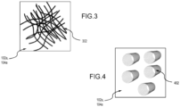
- FIG. 3 in accordance with various embodiments, carbon fibers 302 grown on a surface 102a of a composite preform component and/or on a surface 104a of a second composite preform component are illustrated.
- carbon fibers 302 may be grown on the surface 102a and/or the surface 104a by exposing a metal catalyst particle, such as iron (Fe), cobalt (Co), nickel (Ni), among others, of a few nanometers, e.g.
- carbon nanotubes 402 grown on a surface 102a of a composite preform component and/or on a surface 104a of a second composite preform component are illustrated.
- carbon fibers 302 may be grown on the surface 102a and/or the surface 104a by exposing a metal catalyst particle, such as iron (Fe), cobalt (Co), nickel (Ni), among others, of a few nanometers, e.g. between .5 nanometers (0.01969 microinch) and 9 nanometers (0.3543 microinch), in diameter to a carbon-containing reaction gas, such as hydrogen or carbon monoxide, among others, supersaturated in carbon in a high-temperature furnace.
- a metal catalyst particle such as iron (Fe), cobalt (Co), nickel (Ni), among others, of a few nanometers, e.g. between .5 nanometers (0.01969 microinch) and 9 nanometers (0.3543 microinch
- a carbon-containing reaction gas such as hydrogen or carbon monoxide, among others, supersaturated in carbon in a high-temperature furnace.
- the bonding of the C/C components may be enhanced through the utilization of internal carbon dowels.
- FIG. 5 in accordance with various embodiments, a set of holes 502 formed in a first composite preform component 102 and a set of holes 504 formed in a second composite preform component 104 is illustrated.
- the set of holes 502 of a first diameter may be formed by drilling or etching, among others, from a surface 102a into the first composite preform component 102 in a negative x-direction.
- the set of holes 504 of a second diameter may be formed by drilling or etching, among others, from a surface 104a into the second composite preform component 104 in a positive x-direction.
- the first diameter is equal to the second diameter.
- a set of carbon dowels 506 may be formed that have a third diameter that is substantially equal to the first and second diameters.
- the terms "substantially” as used herein represents an amount close to the stated amount that still performs a desired function or achieves a desired result.
- set of carbon dowels 506 may enter respective ones of the set of holes 502 and the set of holes 504.
- thermoset resin or a thermoplastic resin applied to the surface 102a and the set of holes 502, the surface 104a and the set of holes 504, and/or the carbon dowels 506 prior to the surface 102a of the first composite preform component 102 or the surface 104a of the second composite preform component 104 being pressed together may enter and fill the set of holes 502 and the set of holes 504 to increase the bonding to the respective ones of the set of carbon dowels 506.
- each of the set of holes may be up to half the thickness of the first composite preform component 102 or the second composite preform component 104.
- FIG. 6 in accordance with various embodiments, a set of composite preform components joined together to form all or a portion of a composite structure is illustrated.
- surface 102a of the first composite preform component 102 is joined to surface 104a of the second composite preform component 104 via bonding.
- a method of bonding a first C/C component to a second C/C component for high-temperature composite applications is illustrated.
- one or more surfaces of the first C/C component and one or more surfaces of the second C/C component that will be joined together are prepared for joining.
- the one or more surfaces of the first C/C component and the one or more surfaces of the second C/C component may be prepared via surface etching performed by high temperature "burning," physical scratching (e.g., with abrasives and/or blasting with abrasive media), surface grinding, or plasma deformation that utilizes oxygen, nitrogen, argon, or air, there by forming a Ra value of roughness, such as between 3.2 micrometers (126 microinches) and 1.2 micrometers (47.24 microinches).
- the one or more surfaces of the first C/C component and the one or more surfaces of the second C/C component may be prepared via growing carbon nanofibers or carbon nanotubes on the surfaces of the bonding areas of the C/C components.
- the one or more surfaces of the first C/C component and the one or more surfaces of the second C/C component may be prepared via a utilization of internal carbon dowels.
- the one or more surfaces of the first C/C component and the one or more surfaces of the second C/C component may be prepared via an introduction of nitrogen (N) or sulfur (S) compounds directly on the surfaces of the bonding areas of the C/C components.
- the one or more surfaces of the first C/C component and the one or more surfaces of the second C/C component may be prepared via cold spraying the surfaces of the bonding areas of the C/C components with a carbon powder, e.g. isotropic pitch powder or mesophase pitch powder, among others.
- a carbon powder e.g. isotropic pitch powder or mesophase pitch powder, among others.
- an adhesive such as a slurry or paste, may be created utilizing a bonding adhesive.
- the bonding adhesive may be a high-temperature capable bonding adhesive or a melt-resistant bonding adhesive.
- the bonding adhesive may be silicon free.
- the bonding adhesive may include thermoset resins, e.g. a phenolic-based resin, a polyimide-based resin, or a polybenzoxazine-based resins, or thermoplastic resins, e.g. isotropic pitch, mesophase pitch, polyetheretherketone (PEEK), or polyaryleetherketones (PAEK), among others.
- the bonding adhesive including the thermoset resin or the thermoplastic resin may further include a fugitive compound.
- the fugitive compound volatilizes and forms porous channels in the bonding adhesive during at least one of curing or a heat-treating process and creates pathways for infiltration of gases during a chemical vapor infiltration operation to promote densification and improve a bonding strength.
- the slurry or paste may be reinforced by adding, e.g. chopped carbon fiber, carbon nanotubes, carbon nanofibers, graphene, or powdered diamond dust, among others to the thermoset and thermoplastic resins.
- the slurry or paste may be applied to a surface of a first composite preform component and a surface of a second composite preform component that are to be joined.
- the surface of the first composite preform component and the surface of the second composite preform component are pressed together.
- the composite preforms may be pressed together by vacuum-bagging (i.e., negative pressure) or using vacuum bagging and autoclave pressure (i.e., positive pressure).
- the composite preforms may be pressed together using flexible caul plates and pressurized bladders or using an actuated platen press, among others, to apply uniform pressure and compaction.
- the joined composite preform component may be cured.
- the joined composite preform component may be heat treated with temperatures that reach 4000 degrees Fahrenheit (2204 degree Celsius) or above.
- the joined composite preform component may then undergo chemical vapor infiltration (CVI) densification or chemical vapor deposition (CVD).
- CVI is a technique where the joined composite preform component are infiltrated using reactive gases at elevated temperature to form fiber-reinforced joined composite preform component.
- CVD is a technique in which substances that are in vapor phase are condensed into the joined composite preform component to generate a solid phase material.
- references to "one embodiment,” “an embodiment,” “various embodiments,” etc. indicate that the embodiment described may include a particular feature, structure, or characteristic, but every embodiment may not necessarily include the particular feature, structure, or characteristic. Moreover, such phrases are not necessarily referring to the same embodiment. Further, when a particular feature, structure, or characteristic is described in connection with an embodiment, it is submitted that it is within the knowledge of one skilled in the art to affect such feature, structure, or characteristic in connection with other embodiments whether or not explicitly described. After reading the description, it will be apparent to one skilled in the relevant art(s) how to implement the disclosure in alternative embodiments.
- Numbers, percentages, or other values stated herein are intended to include that value, and also other values that are about or approximately equal to the stated value, as would be appreciated by one of ordinary skill in the art encompassed by various embodiments of the present disclosure.
- a stated value should therefore be interpreted broadly enough to encompass values that are at least close enough to the stated value to perform a desired function or achieve a desired result.
- the stated values include at least the variation to be expected in a suitable industrial process, and may include values that are within 10%, within 5%, within 1%, within 0.1%, or within 0.01% of a stated value.
- the terms “substantially,” “about,” or “approximately” as used herein represent an amount close to the stated amount that still performs a desired function or achieves a desired result.
- the term “substantially,” “about,” or “approximately” may refer to an amount that is within 10% of, within 5% of, within 1% of, within 0.1% of, and within 0.01% of a stated amount or value
Landscapes
- Chemical & Material Sciences (AREA)
- Organic Chemistry (AREA)
- Engineering & Computer Science (AREA)
- Ceramic Engineering (AREA)
- Mechanical Engineering (AREA)
- Chemical Kinetics & Catalysis (AREA)
- Materials Engineering (AREA)
- General Chemical & Material Sciences (AREA)
- Structural Engineering (AREA)
- Metallurgy (AREA)
- Inorganic Chemistry (AREA)
- Manufacturing & Machinery (AREA)
- Composite Materials (AREA)
- Ceramic Products (AREA)
- Lining Or Joining Of Plastics Or The Like (AREA)
Abstract
Description
- The present disclosure relates generally to composite preform components and, more particularly, to bonding for high-temperature composite applications.
- Shaped composite bodies are utilized in aerospace applications. Various systems and methods are known in the art for joining composite preform components. Many methods for joining or bonding of a carbon-carbon (C/C) part to another C/C part used for high-temperature applications utilize resins and resin mixtures containing silicon (Si)-based or silicon carbide (SiC)-based compounds.
- According to various embodiments of the present disclosure, a manufacturing method is provided. The method includes applying a bonding adhesive to at least one of a first surface of a first composite preform component or a first surface of a second composite preform component; and joining the first surface of the first composite preform component to the first surface of the second composite preform component.
- In various embodiments, the bonding adhesive is silicon-free and includes at least one of a thermoset resin or a thermoplastic resin. In various embodiments, the thermoset resin is at least one of a phenolic-based resin, a polyimide-based resin, or a polybenzoxazine-based resin. In various embodiments, the thermoplastic resin is at least one of an isotropic pitch, mesophase pitch, polyetheretherketone (PEEK), or polyaryleetherketones (PAEK). In various embodiments, the bonding adhesive is reinforced with at least one of chopped carbon fiber, carbon nanotubes, carbon nanofibers, graphene, or powdered diamond dust. In various embodiments, the at least one of the first surface of the first composite preform component or the first surface of the second composite preform component are prepared by surface etching the at least one of the first surface of the first composite preform component and the first surface of the second composite preform component. In various embodiments, the surface etching includes at least one of high-temperature burning, physical scratching, surface grinding, or plasma deformation.
- In various embodiments, the at least one of the first surface of the first composite preform component or the first surface of the second composite preform component are prepared by growing carbon nanofibers or carbon nanotubes on the at least one of the first surface of the first composite preform component or the first surface of the second composite preform component. In various embodiments, the at least one of the first surface of the first composite preform component or the first surface of the second composite preform component are prepared by drilling holes in the first surface of the first composite preform component and the first surface of the second composite preform component for joining using a set of internal carbon dowels. In various embodiments, the at least one of the first surface of the first composite preform component or the first surface of the second composite preform component are prepared by an introduction of nitrogen (N) or sulfur (S) compounds directly on the at least one of the first surface of the first composite preform component or the first surface of the second composite preform component. In various embodiments, the at least one of the first surface of the first composite preform component or the first surface of the second composite preform component are prepared by cold spraying the at least one of the first surface of the first composite preform component or the first surface of the second composite preform component with a carbon powder.
- Also disclosed herein is a manufacturing method that includes preparing at least one of a first surface of a first composite preform component or a first surface of a second composite preform component for joining; applying a bonding adhesive to the at least one of the first surface of the first composite preform component or the first surface of the second composite preform component; pressing the first surface of the first composite preform component and the first surface of the second composite preform component together to form a joined composite preform component; curing the joined composite preform component; heat treating the joined composite preform component; and performing either chemical vapor infiltration (CVI) densification or chemical vapor deposition (CVD) on the joined composite preform component.
- In various embodiments, the bonding adhesive is silicon free and includes at least one of a thermoset resin or a thermoplastic resin. In various embodiments, the bonding adhesive including the at least one of the thermoset resin or the thermoplastic resin further includes a fugitive compound. In various embodiments, the fugitive compound volatilizes and forms porous channels in the bonding adhesive during at least one of the curing or the heat treating and creates pathways for infiltration of gases during a chemical vapor infiltration operation to promote densification and improve a bonding strength. In various embodiments, the thermoset resin is at least one of a phenolic-based resin, a polyimide-based resin, or a polybenzoxazine-based resin. In various embodiments, the thermoplastic resin is at least one of an isotropic pitch, mesophase pitch, polyetheretherketone (PEEK), or polyaryleetherketones (PAEK). In various embodiments, the bonding adhesive is reinforced with at least one of chopped carbon fiber, carbon nanotubes, carbon nanofibers, graphene, or powdered diamond dust.
- In various embodiments, the at least one of the first surface of the first composite preform component or the first surface of the second composite preform component are prepared by surface etching the at least one of the first surface of the first composite preform component and the first surface of the second composite preform component and wherein the surface etching includes at least one of high-temperature burning, physical scratching, surface grinding, or plasma deformation. In various embodiments, the at least one of the first surface of the first composite preform component or the first surface of the second composite preform component are prepared by growing carbon nanofibers or carbon nanotubes on the at least one of the first surface of the first composite preform component or the first surface of the second composite preform component.
- In various embodiments, the at least one of the first surface of the first composite preform component or the first surface of the second composite preform component are prepared by drilling holes in the first surface of the first composite preform component and the first surface of the second composite preform component for joining using a set of internal carbon dowels. In various embodiments, the at least one of the first surface of the first composite preform component or the first surface of the second composite preform component are prepared by an introduction of nitrogen (N) or sulfur (S) compounds directly on the at least one of the first surface of the first composite preform component or the first surface of the second composite preform component. In various embodiments, the at least one of the first surface of the first composite preform component or the first surface of the second composite preform component are prepared by cold spraying the at least one of the first surface of the first composite preform component or the first surface of the second composite preform component with a carbon powder.
- Also disclosed herein is a bonding adhesive for joining a first surface of a first composite preform component to a first surface of a second composite preform component. The bonding adhesive includes at least one of a high temperature capable bonding adhesive or melt-resistant bonding adhesive; and at least one of a thermoset resin or a thermoplastic resin.
- In various embodiments, the thermoset resin is at least one of a phenolic-based resin, a polyimide-based resin, or a polybenzoxazine-based resin. In various embodiments, the thermoplastic resin is at least one of an isotropic pitch, mesophase pitch, polyetheretherketone (PEEK), or polyaryleetherketones (PAEK). In various embodiments, the bonding adhesive is reinforced with at least one of chopped carbon fiber, carbon nanotubes, carbon nanofibers, graphene, or powdered diamond dust.
- The present disclosure may include any one or more of the individual features disclosed above and/or below alone or in any combination thereof.
- The foregoing features and elements may be combined in various combinations without exclusivity, unless expressly indicated herein otherwise. These features and elements as well as the operation of the disclosed embodiments will become more apparent in light of the following description and accompanying drawings.
-
-
FIG. 1 illustrates a set of composite preform components to be joined together to form all or a portion of a composite structure, in accordance with various embodiments. -
FIGS. 2A and 2B illustrate deformations of a cross section of the surface of the first composite preform component or the surface of the second composite preform component, in accordance with various embodiments. -
FIG. 3 illustrates carbon fibers grown on a surface of a composite preform component and/or on a surface of a second composite preform component, in accordance with various embodiments. -
FIG. 4 illustrates carbon nanotubes grown on a surface of a composite preform component and/or on a surface of a second composite preform component, in accordance with various embodiments. -
FIG. 5 illustrates a set of holes formed in a first composite preform component and a set of holes formed in a second composite preform component, in accordance with various embodiments. -
FIG. 6 illustrates a set of composite preform components joined together to form all or a portion of a composite structure, in accordance with various embodiments. -
FIG. 7 illustrates a method of bonding a first C/C component to a second C/C component for high-temperature composite applications, in accordance with various embodiments. - The following detailed description of various embodiments herein makes reference to the accompanying drawings, which show various embodiments by way of illustration. While these various embodiments are described in sufficient detail to enable those skilled in the art to practice the disclosure, it should be understood that other embodiments may be realized and that changes may be made without departing from the scope of the disclosure. Thus, the detailed description herein is presented for purposes of illustration only and not of limitation. Furthermore, any reference to singular includes plural embodiments, and any reference to more than one component or step may include a singular embodiment or step. Also, any reference to attached, fixed, connected, or the like may include permanent, removable, temporary, partial, full or any other possible attachment option. Additionally, any reference to without contact (or similar phrases) may also include reduced contact or minimal contact. It should also be understood that unless specifically stated otherwise, references to "a," "an," or "the" may include one or more than one and that reference to an item in the singular may also include the item in the plural. Further, all ranges may include upper and lower values and all ranges and ratio limits disclosed herein may be combined.
- Typical joining or bonding of a carbon-carbon (C/C) part to a monolith or other C/C part used for high-temperature applications utilize phenolic resins, which are silicon (Si)-based or silicon carbide (SiC)-based resins. However, utilizing Si-based or SiC-based resins in the bonding area may cause mismatch issues. That is, phenolic resin bonding provides disadvantages such as low carbon yield (less than 60% yield), low graphitizability (i.e. phenolic resin-based carbon is not very graphitizable), and/or low thermal properties (i.e. thermal conductivity), among others.
- Disclosed herein are systems and methods for bonding C/C components for high-temperature composite applications. In various embodiments, silicon-free (Si-free) or pure C/C bonding technology is utilized to bond a first C/C component to a second C/C component for high-temperature structural C/C applications where the operating temperature may reach 4000 degrees Fahrenheit (2204 degree Celsius) or above. In various embodiments, the phenolic resins are replaced with a bonding adhesive. In various embodiments, the bonding adhesive may be a high-temperature capable bonding adhesive or a melt-resistant bonding adhesive. In various embodiments, the bonding adhesive may be silicon free. In various embodiments, the bonding adhesive may include a thermoset resin, e.g. a phenolic-based resin, a polyimide-based resin, or a polybenzoxazine-based resin, among others, or a thermoplastic resin, e.g. isotropic pitch, mesophase pitch, polyetheretherketone (PEEK), or polyaryleetherketones (PAEK), among others. In various embodiments, the thermoset and thermoplastic resins may be reinforced by adding, e.g. chopped carbon fiber, carbon nanotubes, carbon nanofibers, graphene, or powdered diamond dust, among others, to the thermoset and thermoplastic resins. In various embodiments, the bonding of the C/C components may be enhanced by growing carbon nanofibers or carbon nanotubes on the surfaces of the bonding areas of the C/C components. In various embodiments, the bonding of the C/C components may be enhanced through the utilization of internal carbon dowels. In various embodiments, the bonding of the C/C components may be enhanced by creating high contact surface areas between the C/C components, e.g. surface roughness. In various embodiments, the bonding of the C/C components may be enhanced by introducing nitrogen (N2) or sulfur (S) compounds directly on the surfaces of the bonding areas of the C/C components. In various embodiments, the bonding of the C/C components may be enhanced by cold spraying the surfaces of the bonding areas of the C/C components with a carbon powder, e.g. isotropic pitch powder or mesophase pitch powder, among others.
- Referring now to
FIG. 1 , in accordance with various embodiments, a set of composite preform components to be joined together to form all or a portion of a composite structure is illustrated.Composite structure 100 includes a firstcomposite preform component 102 and a secondcomposite preform component 104. In various embodiments, both of the firstcomposite preform component 102 and the secondcomposite preform component 104 may have a complex shape having portions formed in in a fist direction, i.e., in a x-direction, in a second direction, i.e., in a y-direction, and in a third direction, i.e., a z-direction, or any combination thereof. In various embodiments, parts of the firstcomposite preform component 102 are joined to parts of the secondcomposite preform component 104 to form an even more complex shape. For example, in various embodiments,surface 102a of the firstcomposite preform component 102 may be joined tosurface 104a of the secondcomposite preform component 104 via bonding. - As described previously, in various embodiments, the bonding of the C/C components may be enhanced by creating high contact surface areas between the C/C components. In various embodiments, the high contact surfaces area having relatively high surface roughness, which increases the total bonding surface area per square meter, may be generated via surface etching performed by high temperature "burning," physical scratching (e.g., with abrasives and/or blasting with abrasive media), surface grinding, or plasma deformation that utilizes oxygen, nitrogen, argon, or air, there by forming a Arithmetic Average Roughness (Ra) value of roughness, such as between 3.2 micrometers (126 microinches) and 1.2 micrometers (47.24 microinches). Turning to
FIGS. 2A and 2B , in accordance with various embodiments, deformations of a cross section of thesurface 102a of the firstcomposite preform component 102 or thesurface 104a of the secondcomposite preform component 104 is illustrated. In various embodiments, thesurface 102a or thesurface 104a may be deformed from a smooth surface to encompass holes, ridges, or contours, among others. In various embodiments, the deformations may be implemented by using a tool with a high-temperature tip that, when the high-temperature tip contacts thesurface 102a or thesurface 104a, the surface is deformed from being a smooth surface. In various embodiments, the deformations may be implemented by physically scratching thesurface 102a or thesurface 104a with a tool so as to deform the surface from a smooth surface state. In various embodiments, the deformations may be implemented by grinding thesurface 102a or thesurface 104a via a grinding tool or machine that utilizes an abrasive wheel or attachment to remove portions of the surface. In various embodiments, the deformations may be implemented by using a plasma tool that utilizes oxygen, nitrogen, argon, or air, among others, to deform the surface from a smooth surface state. - With particular reference to
FIG. 2A , thesurface 102a may be deformed to have a set ofpositive ridges 202 extending in the positive x-direction andsurface 104a may be deformed to have a set ofnegative ridges 204 extending in the positive x-direction such that, responsive to thesurface 102a of the firstcomposite preform component 102 and thesurface 104a of the secondcomposite preform component 104 being pressed together, the set ofpositive ridges 202 protrude into the set ofnegative ridges 204. It is noted that a thermoset resin or a thermoplastic resin may be applied to thesurface 102a and/or thesurface 104a prior to thesurface 102a of the firstcomposite preform component 102 and thesurface 104a of the secondcomposite preform component 104 being pressed together. - With particular reference to
FIG. 2B , thesurface 102a and thesurface 104a may be deformed to have a plurality of holes, ridges, orcontours 206, among others, some of which may align with each other while others of which do not align with each other. In that regard, responsive to thesurface 102a of the firstcomposite preform component 102 and thesurface 104a of the secondcomposite preform component 104 being pressed together, a thermoset resin or a thermoplastic resin applied to thesurface 102a and/or thesurface 104a prior to thesurface 102a of the firstcomposite preform component 102 and thesurface 104a of the secondcomposite preform component 104 being pressed together, may enter and fill the plurality of holes, ridges, orcontours 206, among others, to increase the bonding surface area. - As described previously, in various embodiments, the bonding of the C/C components may be enhanced by growing carbon nanofibers or carbon nanotubes on the surfaces of the bonding areas of the C/C components. Turning to
FIG. 3 , in accordance with various embodiments,carbon fibers 302 grown on asurface 102a of a composite preform component and/or on asurface 104a of a second composite preform component are illustrated. In various embodiments,carbon fibers 302 may be grown on thesurface 102a and/or thesurface 104a by exposing a metal catalyst particle, such as iron (Fe), cobalt (Co), nickel (Ni), among others, of a few nanometers, e.g. between .5 nanometers (0.01969 microinch) and 9 nanometers (0.3543 microinch), in diameter to a gas, such as benzene and methane, supersaturated in carbon. Under these conditions, the catalyst particles can produce rapidly lengthening carbon filaments of nanometer diameter. Turning toFIG. 4 , in accordance with various embodiments,carbon nanotubes 402 grown on asurface 102a of a composite preform component and/or on asurface 104a of a second composite preform component are illustrated. In various embodiments,carbon fibers 302 may be grown on thesurface 102a and/or thesurface 104a by exposing a metal catalyst particle, such as iron (Fe), cobalt (Co), nickel (Ni), among others, of a few nanometers, e.g. between .5 nanometers (0.01969 microinch) and 9 nanometers (0.3543 microinch), in diameter to a carbon-containing reaction gas, such as hydrogen or carbon monoxide, among others, supersaturated in carbon in a high-temperature furnace. - As described previously, in various embodiments, the bonding of the C/C components may be enhanced through the utilization of internal carbon dowels. Turning to
FIG. 5 , in accordance with various embodiments, a set ofholes 502 formed in a firstcomposite preform component 102 and a set ofholes 504 formed in a secondcomposite preform component 104 is illustrated. In various embodiments, the set ofholes 502 of a first diameter may be formed by drilling or etching, among others, from asurface 102a into the firstcomposite preform component 102 in a negative x-direction. In various embodiments, the set ofholes 504 of a second diameter may be formed by drilling or etching, among others, from asurface 104a into the secondcomposite preform component 104 in a positive x-direction. In various embodiments, the first diameter is equal to the second diameter. In various embodiments, a set ofcarbon dowels 506 may be formed that have a third diameter that is substantially equal to the first and second diameters. In various embodiments, the terms "substantially" as used herein represents an amount close to the stated amount that still performs a desired function or achieves a desired result. For example, the term "substantially" may refer to an amount that is within 10% of, within 5% of, within 1% of, within 0.1% of, and within 0.01% of a stated amount or value. In various embodiments, responsive to thesurface 102a of the firstcomposite preform component 102 and thesurface 104a of the secondcomposite preform component 104 being pressed together, set ofcarbon dowels 506 enter respective ones of the set ofholes 502 and the set ofholes 504. In that regard, responsive to thesurface 102a of the firstcomposite preform component 102 or thesurface 104a of the secondcomposite preform component 104 being pressed together, a thermoset resin or a thermoplastic resin applied to thesurface 102a and the set ofholes 502, thesurface 104a and the set ofholes 504, and/or the carbon dowels 506 prior to thesurface 102a of the firstcomposite preform component 102 or thesurface 104a of the secondcomposite preform component 104 being pressed together, may enter and fill the set ofholes 502 and the set ofholes 504 to increase the bonding to the respective ones of the set of carbon dowels 506. In various embodiments, each of the set of holes may be up to half the thickness of the firstcomposite preform component 102 or the secondcomposite preform component 104. - Turning to
FIG. 6 , in accordance with various embodiments, a set of composite preform components joined together to form all or a portion of a composite structure is illustrated. In various embodiments,surface 102a of the firstcomposite preform component 102 is joined tosurface 104a of the secondcomposite preform component 104 via bonding. - Referring now to
FIG. 7 , in accordance with various embodiments, a method of bonding a first C/C component to a second C/C component for high-temperature composite applications, is illustrated. Atblock 702, one or more surfaces of the first C/C component and one or more surfaces of the second C/C component that will be joined together are prepared for joining. In various embodiments, the one or more surfaces of the first C/C component and the one or more surfaces of the second C/C component may be prepared via surface etching performed by high temperature "burning," physical scratching (e.g., with abrasives and/or blasting with abrasive media), surface grinding, or plasma deformation that utilizes oxygen, nitrogen, argon, or air, there by forming a Ra value of roughness, such as between 3.2 micrometers (126 microinches) and 1.2 micrometers (47.24 microinches). In various embodiments, the one or more surfaces of the first C/C component and the one or more surfaces of the second C/C component may be prepared via growing carbon nanofibers or carbon nanotubes on the surfaces of the bonding areas of the C/C components. In various embodiments, the one or more surfaces of the first C/C component and the one or more surfaces of the second C/C component may be prepared via a utilization of internal carbon dowels. In various embodiments, the one or more surfaces of the first C/C component and the one or more surfaces of the second C/C component may be prepared via an introduction of nitrogen (N) or sulfur (S) compounds directly on the surfaces of the bonding areas of the C/C components. In various embodiments, the one or more surfaces of the first C/C component and the one or more surfaces of the second C/C component may be prepared via cold spraying the surfaces of the bonding areas of the C/C components with a carbon powder, e.g. isotropic pitch powder or mesophase pitch powder, among others. - At
block 704, an adhesive, such as a slurry or paste, may be created utilizing a bonding adhesive. In various embodiments, the bonding adhesive may be a high-temperature capable bonding adhesive or a melt-resistant bonding adhesive. In various embodiments, the bonding adhesive may be silicon free. In various embodiments, the bonding adhesive may include thermoset resins, e.g. a phenolic-based resin, a polyimide-based resin, or a polybenzoxazine-based resins, or thermoplastic resins, e.g. isotropic pitch, mesophase pitch, polyetheretherketone (PEEK), or polyaryleetherketones (PAEK), among others. In various embodiments, the bonding adhesive including the thermoset resin or the thermoplastic resin may further include a fugitive compound. In various embodiments, the fugitive compound volatilizes and forms porous channels in the bonding adhesive during at least one of curing or a heat-treating process and creates pathways for infiltration of gases during a chemical vapor infiltration operation to promote densification and improve a bonding strength. In various embodiments, the slurry or paste may be reinforced by adding, e.g. chopped carbon fiber, carbon nanotubes, carbon nanofibers, graphene, or powdered diamond dust, among others to the thermoset and thermoplastic resins. - At
block 706, the slurry or paste may be applied to a surface of a first composite preform component and a surface of a second composite preform component that are to be joined. Atblock 708, the surface of the first composite preform component and the surface of the second composite preform component are pressed together. In various embodiments, the composite preforms may be pressed together by vacuum-bagging (i.e., negative pressure) or using vacuum bagging and autoclave pressure (i.e., positive pressure). In various embodiments, the composite preforms may be pressed together using flexible caul plates and pressurized bladders or using an actuated platen press, among others, to apply uniform pressure and compaction. - At
block 710, once the composite components are pressed together, the joined composite preform component may be cured. Atblock 712, once cured, the joined composite preform component may be heat treated with temperatures that reach 4000 degrees Fahrenheit (2204 degree Celsius) or above. Atblock 714, the joined composite preform component may then undergo chemical vapor infiltration (CVI) densification or chemical vapor deposition (CVD). CVI is a technique where the joined composite preform component are infiltrated using reactive gases at elevated temperature to form fiber-reinforced joined composite preform component. CVD is a technique in which substances that are in vapor phase are condensed into the joined composite preform component to generate a solid phase material. - Benefits and other advantages have been described herein with regard to specific embodiments. Furthermore, the connecting lines shown in the various figures contained herein are intended to represent exemplary functional relationships and/or physical couplings between the various elements. It should be noted that many alternative or additional functional relationships or physical connections may be present in a practical system. However, the benefits, advantages, and any elements that may cause any benefit or advantage to occur or become more pronounced are not to be construed as critical, required, or essential features or elements of the disclosure. The scope of the disclosure is accordingly to be limited by nothing other than the appended claims, in which reference to an element in the singular is not intended to mean "one and only one" unless explicitly so stated, but rather "one or more." Moreover, where a phrase similar to "at least one of A, B, or C" is used in the claims, it is intended that the phrase be interpreted to mean that A alone may be present in an embodiment, B alone may be present in an embodiment, C alone may be present in an embodiment, or that any combination of the elements A, B and C may be present in a single embodiment; for example, A and B, A and C, B and C, or A and B and C.
- Systems, methods, and apparatus are provided herein. In the detailed description herein, references to "one embodiment," "an embodiment," "various embodiments," etc., indicate that the embodiment described may include a particular feature, structure, or characteristic, but every embodiment may not necessarily include the particular feature, structure, or characteristic. Moreover, such phrases are not necessarily referring to the same embodiment. Further, when a particular feature, structure, or characteristic is described in connection with an embodiment, it is submitted that it is within the knowledge of one skilled in the art to affect such feature, structure, or characteristic in connection with other embodiments whether or not explicitly described. After reading the description, it will be apparent to one skilled in the relevant art(s) how to implement the disclosure in alternative embodiments.
- Numbers, percentages, or other values stated herein are intended to include that value, and also other values that are about or approximately equal to the stated value, as would be appreciated by one of ordinary skill in the art encompassed by various embodiments of the present disclosure. A stated value should therefore be interpreted broadly enough to encompass values that are at least close enough to the stated value to perform a desired function or achieve a desired result. The stated values include at least the variation to be expected in a suitable industrial process, and may include values that are within 10%, within 5%, within 1%, within 0.1%, or within 0.01% of a stated value. Additionally, the terms "substantially," "about," or "approximately" as used herein represent an amount close to the stated amount that still performs a desired function or achieves a desired result. For example, the term "substantially," "about," or "approximately" may refer to an amount that is within 10% of, within 5% of, within 1% of, within 0.1% of, and within 0.01% of a stated amount or value.
- Furthermore, no element, component, or method step in the present disclosure is intended to be dedicated to the public regardless of whether the element, component, or method step is explicitly recited in the claims. No claim element herein is to be construed under the provisions of 35 U.S.C. 112(f) unless the element is expressly recited using the phrase "means for." As used herein, the terms "comprises," "comprising," or any other variation thereof, are intended to cover a non-exclusive inclusion, such that a process, method, article, or apparatus that comprises a list of elements does not include only those elements but may include other elements not expressly listed or inherent to such process, method, article, or apparatus.
- Finally, it should be understood that any of the above-described concepts can be used alone or in combination with any or all of the other above-described concepts. Although various embodiments have been disclosed and described, one of ordinary skill in this art would recognize that certain modifications would come within the scope of this disclosure. Accordingly, the description is not intended to be exhaustive or to limit the principles described or illustrated herein to any precise form. Many modifications and variations are possible in light of the above teaching.
Claims (15)
- A manufacturing method, comprising:applying a bonding adhesive to at least one of a first surface of a first composite preform component or a first surface of a second composite preform component; andjoining the first surface of the first composite preform component to the first surface of the second composite preform component.
- The manufacturing method of claim 1, wherein the bonding adhesive is silicon-free and includes at least one of a thermoset resin or a thermoplastic resin.
- The manufacturing method of claim 2, wherein the thermoset resin is at least one of a phenolic-based resin, a polyimide-based resin, or a polybenzoxazine-based resin and wherein the thermoplastic resin is at least one of an isotropic pitch, mesophase pitch, polyetheretherketone (PEEK), or polyaryleetherketones (PAEK).
- The manufacturing method of any preceding claim, wherein the bonding adhesive is reinforced with at least one of chopped carbon fiber, carbon nanotubes, carbon nanofibers, graphene, or powdered diamond dust.
- The manufacturing method of any preceding claim, wherein the at least one of the first surface of the first composite preform component or the first surface of the second composite preform component are prepared by surface etching the at least one of the first surface of the first composite preform component and the first surface of the second composite preform component.
- The manufacturing method of claim 5, wherein the surface etching includes at least one of high-temperature burning, physical scratching, surface grinding, or plasma deformation.
- The manufacturing method of any of claims 1 to 4, wherein the at least one of the first surface of the first composite preform component or the first surface of the second composite preform component are prepared by growing carbon nanofibers or carbon nanotubes on the at least one of the first surface of the first composite preform component or the first surface of the second composite preform component.
- The manufacturing method of any of claims 1 to 4, wherein the at least one of the first surface of the first composite preform component or the first surface of the second composite preform component are prepared by drilling holes in the first surface of the first composite preform component and the first surface of the second composite preform component for joining using a set of internal carbon dowels.
- The manufacturing method of any of claims 1 to 4, wherein the at least one of the first surface of the first composite preform component or the first surface of the second composite preform component are prepared by an introduction of nitrogen (N) or sulfur (S) compounds directly on the at least one of the first surface of the first composite preform component or the first surface of the second composite preform component.
- The manufacturing method of any of claims 1 to 4, wherein the at least one of the first surface of the first composite preform component or the first surface of the second composite preform component are prepared by cold spraying the at least one of the first surface of the first composite preform component or the first surface of the second composite preform component with a carbon powder.
- A manufacturing method, comprising:preparing at least one of a first surface of a first composite preform component or a first surface of a second composite preform component for joining;applying a bonding adhesive to the at least one of the first surface of the first composite preform component or the first surface of the second composite preform component;pressing the first surface of the first composite preform component and the first surface of the second composite preform component together to form a joined composite preform component;curing the joined composite preform component;heat treating the joined composite preform component; andperforming either chemical vapor infiltration (CVI) densification or chemical vapor deposition (CVD) on the joined composite preform component.
- The manufacturing method of claim 11, wherein the bonding adhesive is silicon free and includes at least one of a thermoset resin or a thermoplastic resin, wherein the bonding adhesive comprising the at least one of the thermoset resin or the thermoplastic resin further comprises a fugitive compound, and wherein the fugitive compound volatilizes and forms porous channels in the bonding adhesive during at least one of the curing or the heat treating and creates pathways for infiltration of gases during a chemical vapor infiltration operation to promote densification and improve a bonding strength, and/or wherein the bonding adhesive is reinforced with at least one of chopped carbon fiber, carbon nanotubes, carbon nanofibers, graphene, or powdered diamond dust.
- The manufacturing method of claim 12, wherein the thermoset resin is at least one of a phenolic-based resin, a polyimide-based resin, or a polybenzoxazine-based resin and wherein the thermoplastic resin is at least one of an isotropic pitch, mesophase pitch, polyetheretherketone (PEEK), or polyaryleetherketones (PAEK).
- The manufacturing method of any of claims 11 to 13, wherein the at least one of the first surface of the first composite preform component or the first surface of the second composite preform component are prepared by surface etching the at least one of the first surface of the first composite preform component and the first surface of the second composite preform component and wherein the surface etching includes at least one of high-temperature burning, physical scratching, surface grinding, or plasma deformation, or wherein the at least one of the first surface of the first composite preform component or the first surface of the second composite preform component are prepared by growing carbon nanofibers or carbon nanotubes on the at least one of the first surface of the first composite preform component or the first surface of the second composite preform component, or wherein the at least one of the first surface of the first composite preform component or the first surface of the second composite preform component are prepared by drilling holes in the first surface of the first composite preform component and the first surface of the second composite preform component for joining using a set of internal carbon dowels, or wherein the at least one of the first surface of the first composite preform component or the first surface of the second composite preform component are prepared by an introduction of nitrogen (N) or sulfur (S) compounds directly on the at least one of the first surface of the first composite preform component or the first surface of the second composite preform component, or wherein the at least one of the first surface of the first composite preform component or the first surface of the second composite preform component are prepared by cold spraying the at least one of the first surface of the first composite preform component or the first surface of the second composite preform component with a carbon powder.
- A bonding adhesive for joining a first surface of a first composite preform component to a first surface of a second composite preform component, the bonding adhesive comprising:at least one of a high temperature capable bonding adhesive or a melt-resistant bonding adhesive; andat least one of a thermoset resin or a thermoplastic resin, wherein the thermoset resin is at least one of a phenolic-based resin, a polyimide-based resin, or a polybenzoxazine-based resin, wherein the thermoplastic resin is at least one of an isotropic pitch, mesophase pitch, polyetheretherketone (PEEK), or polyaryleetherketones (PAEK), and wherein the bonding adhesive is reinforced with at least one of chopped carbon fiber, carbon nanotubes, carbon nanofibers, graphene, or powdered diamond dust.
Applications Claiming Priority (1)
| Application Number | Priority Date | Filing Date | Title |
|---|---|---|---|
| US18/329,452 US12583189B2 (en) | 2023-06-05 | 2023-06-05 | Bonding for high-temperature composite applications |
Publications (2)
| Publication Number | Publication Date |
|---|---|
| EP4474123A2 true EP4474123A2 (en) | 2024-12-11 |
| EP4474123A3 EP4474123A3 (en) | 2025-02-12 |
Family
ID=91375917
Family Applications (1)
| Application Number | Title | Priority Date | Filing Date |
|---|---|---|---|
| EP24179713.3A Withdrawn EP4474123A3 (en) | 2023-06-05 | 2024-06-03 | Bonding of composite preforms for high-temperature composite applications |
Country Status (2)
| Country | Link |
|---|---|
| US (1) | US12583189B2 (en) |
| EP (1) | EP4474123A3 (en) |
Family Cites Families (22)
| Publication number | Priority date | Publication date | Assignee | Title |
|---|---|---|---|---|
| AU8101491A (en) * | 1990-06-29 | 1992-01-23 | Gui Gerard De Jager | A process for manufacturing reinforced composites and filament material for use in said process |
| US5229196A (en) * | 1991-09-27 | 1993-07-20 | Hughes Aircraft Company | Fiber reinforced ceramic glass composites having tailored coefficient of thermal expansion |
| DE69301866T2 (en) | 1992-06-19 | 1996-08-01 | Mitsubishi Gas Chemical Co | Self-adhesive granular carbon materials and high-density carbon articles made therefrom |
| DE19710105A1 (en) * | 1997-03-12 | 1998-09-17 | Sgl Technik Gmbh | Silicon carbide body reinforced with short graphite fibers |
| US5928448A (en) * | 1997-11-01 | 1999-07-27 | Northrop Grumman Corporation | Dowel adhesive method for repair of ceramic matrix composites |
| JP4261130B2 (en) * | 2002-06-18 | 2009-04-30 | 株式会社東芝 | Silicon / silicon carbide composite material |
| US7291407B2 (en) * | 2002-09-06 | 2007-11-06 | Siemens Power Generation, Inc. | Ceramic material having ceramic matrix composite backing and method of manufacturing |
| FR2844510B1 (en) | 2002-09-12 | 2006-06-16 | Snecma Propulsion Solide | THREE-DIMENSIONAL FIBROUS STRUCTURE OF REFRACTORY FIBERS, PROCESS FOR THE PRODUCTION THEREOF AND APPLICATION TO THERMOSTRUCTURAL COMPOSITE MATERIALS |
| US8632651B1 (en) * | 2006-06-28 | 2014-01-21 | Surfx Technologies Llc | Plasma surface treatment of composites for bonding |
| DE102008032176A1 (en) | 2008-07-09 | 2010-01-14 | Henkel Ag & Co. Kgaa | Polymerizable composition |
| US8936694B1 (en) | 2011-03-22 | 2015-01-20 | The Boeing Company | High temperature hybridized molecular functional group adhesion barrier coating and method |
| EP2834308B1 (en) | 2012-06-27 | 2018-04-18 | Toray Industries, Inc. | Benzoxazine resin composition, prepreg, and fiber-reinforced composite material |
| JP6279588B2 (en) | 2012-09-28 | 2018-02-14 | スリーエム イノベイティブ プロパティズ カンパニー | Polybenzoxazine composition |
| US10556831B2 (en) * | 2013-11-01 | 2020-02-11 | Mbda Uk Limited | Method of manufacturing ceramic matrix composite objects |
| US10364195B2 (en) * | 2014-07-28 | 2019-07-30 | Rolls-Royce Corporation | Braze for ceramic and ceramic matrix composite components |
| US9994489B2 (en) * | 2014-12-30 | 2018-06-12 | The Boeing Company | Bonding dissimilar ceramic components |
| FR3040909B1 (en) | 2015-09-16 | 2018-03-16 | Safran Aircraft Engines | FIBROUS PREFORMS FOR TURBOMACHINE DRAWINGS OF COMPOSITE MATERIAL AND METHOD FOR MANUFACTURING SUCH A PREFORM |
| CN106634744A (en) | 2016-12-29 | 2017-05-10 | 内蒙古航天红岗机械有限公司 | High temperature resistant adhesive for carbon materials and preparation method thereof |
| IT201900011760A1 (en) | 2019-07-15 | 2021-01-15 | Petroceramics S P A | METHOD FOR MAKING A COMPONENT IN FIBER-REINFORCED COMPOSITE MATERIAL |
| CN112406213A (en) | 2020-11-18 | 2021-02-26 | 信骅(上海)器材有限公司 | Continuous production method of highly oriented and high-thickness radiating fin and radiating fin |
| CN115403400B (en) | 2022-08-19 | 2023-03-21 | 宏德新材料科技(葫芦岛)股份有限公司 | Aircraft carbon/carbon composite material brake disc repairing method and adhesive used in method |
| US20240253333A1 (en) * | 2023-02-01 | 2024-08-01 | General Electric Company | Composite panels and methods for manufacturing the same |
-
2023
- 2023-06-05 US US18/329,452 patent/US12583189B2/en active Active
-
2024
- 2024-06-03 EP EP24179713.3A patent/EP4474123A3/en not_active Withdrawn
Non-Patent Citations (3)
| Title |
|---|
| ANONYMOUS HASAN H�SEYIN ET AL: "Characterization and Adhesive Performance of Phenol-Formaldehyde Resol Resin Reinforced with Carbon Nanotubes", BIORESOURCES, vol. 17, no. 3, 30 June 2022 (2022-06-30), US, pages 4781 - 4792, XP093339953, ISSN: 1930-2126, Retrieved from the Internet <URL:https://acikerisim.duzce.edu.tr/items/3f0d7414-cefc-4a2b-b8da-0067a2109385?utm_source=chatgpt.com> DOI: 10.15376/biores.17.3.4781-4792 * |
| HSIAO K-T ET AL: "USE OF EPOXY/MULTIWALLED CARBON NANOTUBES AS ADHESIVES TO JOIN GRAPHITE FIBRE REINFORCED POLYMER COMPOSITES", NANOTECHNOLOGY, IOP PUBLISHING, ENGLAND, vol. 14, no. 7, 1 July 2003 (2003-07-01), pages 791 - 793, XP001169320, ISSN: 0957-4484, DOI: 10.1088/0957-4484/14/7/316 * |
| VIETRI U ET AL: "Nanofilled epoxy adhesive for structural aeronautic materials", COMPOSITES PART B, ELSEVIER, AMSTERDAM, NL, vol. 61, 27 January 2014 (2014-01-27), pages 73 - 83, XP028657686, ISSN: 1359-8368, DOI: 10.1016/J.COMPOSITESB.2014.01.032 * |
Also Published As
| Publication number | Publication date |
|---|---|
| US20240399671A1 (en) | 2024-12-05 |
| EP4474123A3 (en) | 2025-02-12 |
| US12583189B2 (en) | 2026-03-24 |
Similar Documents
| Publication | Publication Date | Title |
|---|---|---|
| EP1326813B1 (en) | Boron carbide based ceramic matrix composites | |
| CN108610080B (en) | Preparation method of carbon-carbon composite material with inner hole and carbon-ceramic composite material | |
| US11117838B2 (en) | Method of making a fiber preform for ceramic matrix composite (CMC) fabrication | |
| JPH10251065A (en) | Carbon fiber reinforced composite material and its production | |
| JP2014518832A (en) | Method for producing ceramic member combined from a plurality of preforms | |
| CN112628325B (en) | Method for producing a composite fiber preform for a disc brake | |
| US20100003402A1 (en) | Method for manufacturing ceramic matrix composite structures | |
| JP2003238265A (en) | Method for producing hollow body made of fiber reinforced ceramic material | |
| US12583189B2 (en) | Bonding for high-temperature composite applications | |
| CN114276157A (en) | High-purity carbon-based composite material | |
| CN113277866A (en) | Preparation method of bidirectional high-thermal-conductivity carbon/carbon composite material | |
| US10723660B2 (en) | Carbon yielding resin for melt infiltration | |
| EP4140968B1 (en) | Method for manufacturing composite fiber preform for disc brakes | |
| EP4137313A1 (en) | Method for manufacturing composite fiber preform for disc brakes | |
| US11852416B2 (en) | Carbon fiber, carbon composite and furnace purification by hydrogen reduction followed by thermal heat treatment | |
| JP2607409B2 (en) | Oxidation-resistant treatment of carbon fiber reinforced carbon composites. | |
| JP2020506866A (en) | Melt impregnation with SiGa and / or SiIn alloy | |
| Dhakate et al. | Development of vapor grown carbon fibers (VGCF) reinforced carbon/carbon composites | |
| JP3599791B2 (en) | Oxidation-resistant treatment of carbon fiber reinforced carbon composites | |
| CN117865700B (en) | SiC/SiC composite material for hot end part of aero-engine and preparation method thereof | |
| JP2002211984A (en) | Method for producing SiC or C fiber / SiC composite material | |
| JP3548597B2 (en) | Oxidation-resistant treatment method of carbon fiber reinforced carbon composite | |
| CN119308950B (en) | Carbon ceramic brake discs and their preparation methods, braking systems and vehicles | |
| US20250019313A1 (en) | Fast densified carbon-carbon composites and fabrication method | |
| CN115745645B (en) | Preparation method of large-component C/C composite material blank |
Legal Events
| Date | Code | Title | Description |
|---|---|---|---|
| PUAI | Public reference made under article 153(3) epc to a published international application that has entered the european phase |
Free format text: ORIGINAL CODE: 0009012 |
|
| STAA | Information on the status of an ep patent application or granted ep patent |
Free format text: STATUS: THE APPLICATION HAS BEEN PUBLISHED |
|
| AK | Designated contracting states |
Kind code of ref document: A2 Designated state(s): AL AT BE BG CH CY CZ DE DK EE ES FI FR GB GR HR HU IE IS IT LI LT LU LV MC ME MK MT NL NO PL PT RO RS SE SI SK SM TR |
|
| PUAL | Search report despatched |
Free format text: ORIGINAL CODE: 0009013 |
|
| AK | Designated contracting states |
Kind code of ref document: A3 Designated state(s): AL AT BE BG CH CY CZ DE DK EE ES FI FR GB GR HR HU IE IS IT LI LT LU LV MC ME MK MT NL NO PL PT RO RS SE SI SK SM TR |
|
| RIC1 | Information provided on ipc code assigned before grant |
Ipc: B29B 11/16 20060101AFI20250108BHEP |
|
| RAP1 | Party data changed (applicant data changed or rights of an application transferred) |
Owner name: GOODRICH CORPORATION |
|
| STAA | Information on the status of an ep patent application or granted ep patent |
Free format text: STATUS: REQUEST FOR EXAMINATION WAS MADE |
|
| 17P | Request for examination filed |
Effective date: 20250811 |
|
| STAA | Information on the status of an ep patent application or granted ep patent |
Free format text: STATUS: EXAMINATION IS IN PROGRESS |
|
| 17Q | First examination report despatched |
Effective date: 20251204 |
|
| STAA | Information on the status of an ep patent application or granted ep patent |
Free format text: STATUS: THE APPLICATION HAS BEEN WITHDRAWN |
|
| 18W | Application withdrawn |
Effective date: 20260312 |