EP4474058A1 - Chipper discharge spout and chipper with compact spout in transport position - Google Patents
Chipper discharge spout and chipper with compact spout in transport position Download PDFInfo
- Publication number
- EP4474058A1 EP4474058A1 EP24179757.0A EP24179757A EP4474058A1 EP 4474058 A1 EP4474058 A1 EP 4474058A1 EP 24179757 A EP24179757 A EP 24179757A EP 4474058 A1 EP4474058 A1 EP 4474058A1
- Authority
- EP
- European Patent Office
- Prior art keywords
- spout
- chipper
- discharge spout
- discharge
- mounting elements
- Prior art date
- Legal status (The legal status is an assumption and is not a legal conclusion. Google has not performed a legal analysis and makes no representation as to the accuracy of the status listed.)
- Granted
Links
Images


Classifications
-
- B—PERFORMING OPERATIONS; TRANSPORTING
- B02—CRUSHING, PULVERISING, OR DISINTEGRATING; PREPARATORY TREATMENT OF GRAIN FOR MILLING
- B02C—CRUSHING, PULVERISING, OR DISINTEGRATING IN GENERAL; MILLING GRAIN
- B02C18/00—Disintegrating by knives or other cutting or tearing members which chop material into fragments
- B02C18/06—Disintegrating by knives or other cutting or tearing members which chop material into fragments with rotating knives
- B02C18/14—Disintegrating by knives or other cutting or tearing members which chop material into fragments with rotating knives within horizontal containers
-
- B—PERFORMING OPERATIONS; TRANSPORTING
- B02—CRUSHING, PULVERISING, OR DISINTEGRATING; PREPARATORY TREATMENT OF GRAIN FOR MILLING
- B02C—CRUSHING, PULVERISING, OR DISINTEGRATING IN GENERAL; MILLING GRAIN
- B02C21/00—Disintegrating plant with or without drying of the material
- B02C21/02—Transportable disintegrating plant
-
- B—PERFORMING OPERATIONS; TRANSPORTING
- B02—CRUSHING, PULVERISING, OR DISINTEGRATING; PREPARATORY TREATMENT OF GRAIN FOR MILLING
- B02C—CRUSHING, PULVERISING, OR DISINTEGRATING IN GENERAL; MILLING GRAIN
- B02C21/00—Disintegrating plant with or without drying of the material
- B02C21/02—Transportable disintegrating plant
- B02C21/026—Transportable disintegrating plant self-propelled
-
- B—PERFORMING OPERATIONS; TRANSPORTING
- B02—CRUSHING, PULVERISING, OR DISINTEGRATING; PREPARATORY TREATMENT OF GRAIN FOR MILLING
- B02C—CRUSHING, PULVERISING, OR DISINTEGRATING IN GENERAL; MILLING GRAIN
- B02C18/00—Disintegrating by knives or other cutting or tearing members which chop material into fragments
- B02C18/06—Disintegrating by knives or other cutting or tearing members which chop material into fragments with rotating knives
- B02C18/16—Details
- B02C18/22—Feed or discharge means
- B02C18/2216—Discharge means
-
- B—PERFORMING OPERATIONS; TRANSPORTING
- B02—CRUSHING, PULVERISING, OR DISINTEGRATING; PREPARATORY TREATMENT OF GRAIN FOR MILLING
- B02C—CRUSHING, PULVERISING, OR DISINTEGRATING IN GENERAL; MILLING GRAIN
- B02C2201/00—Codes relating to disintegrating devices adapted for specific materials
- B02C2201/06—Codes relating to disintegrating devices adapted for specific materials for garbage, waste or sewage
- B02C2201/066—Codes relating to disintegrating devices adapted for specific materials for garbage, waste or sewage for garden waste
Definitions
- the invention relates to construction of the chipper discharge spout and the chipper with a compact discharge spout in the transport position as a mobile device intended for crushing, chipping of wood waste, in particular of garden, forest and park waste.
- the invention falls within the field of wood processing machines especially for gardeners, arborists, landscape architects.
- the above mentioned deficiencies of the chippers are eliminated by construction of the chipper discharge spout and the chipper itself with the included chipper discharge spouts according to the invention.
- the chipper discharge spout comprising the lower spout part, and the upper spout part is solved.
- Substance of construction of the chipper discharge spout is that it is mountable, wherein the upper spout part and the lower spout part have rotary flanges which, in the working position, are connected to each other by first mounting elements and nuts or other clamping mechanisms known to those skilled in the art.
- the first mounting elements are located on the rotary flange of the lower part of the discharge spout.
- the second mounting elements are located on the vertical wall of the lower spout part for use in the transport position, when the upper spout part with the rotary flange is dismantled and then clamped by nuts or other clamping elements against the second mounting elements on the vertical wall of the lower spout part.
- Substance of construction of the chipper itself with the compact mounting of the discharge spout in the transport position is that the dismantled upper part of the spout with the rotary flange is by means of the second mounting elements and nuts detachably connected with the vertical wall of the lower part of the spout.
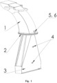
- the construction of the chipper discharge spout according to the invention is described as illustrated in Fig. 1 .
- the chipper discharge spout is mountable.
- the upper part 1 of the spout and the lower part 3 of the spout have rotary flanges 2, which in the working position are detachably connected to each other by first mounting elements 5 and nuts 6 as illustrated in Fig. 1 .
- the first mounting elements 5 are located on the rotary flange 2 of the lower part 3 of the spout.
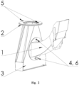
- the second mounting elements 4 applicable for the transport position are located on the vertical wall of the lower part 3 of the spout as shown in Fig. 2 .
- the construction of the chipper 7 itself comprising the compact discharge spout arrangement in the working position according to the invention as illustrated in Fig. 3 .
- the chipper 7 has an upper part 1 of the spout and a lower part 3 of the spout with rotary flanges 2 connected to each other by the first mounting elements 5 and nuts 6.
- the chipper 7 with the included compact spout arrangement in the transport position according to the invention has a dismantled upper part 1 of the discharge spout with rotary flanges 2 fixed by the second mounting elements 4 and nuts 6 against the vertical wall of the lower part 3 of the spout as illustrated in Fig. 4 .
- the chipper discharge spout and chipper with compact arrangement of the discharge spout in the transport position according to the invention can be used wherever wood or green waste suitable for such processing arises, especially in gardens, parks, orchards, golf courses but also in forests.
Landscapes
- Engineering & Computer Science (AREA)
- Food Science & Technology (AREA)
- Debarking, Splitting, And Disintegration Of Timber (AREA)
- Crushing And Pulverization Processes (AREA)
Abstract
Description
- The invention relates to construction of the chipper discharge spout and the chipper with a compact discharge spout in the transport position as a mobile device intended for crushing, chipping of wood waste, in particular of garden, forest and park waste. The invention falls within the field of wood processing machines especially for gardeners, arborists, landscape architects.
- In the state of the art, known crusher/chippers are designed and constructed in such a way that the discharge spout of the chipper can be dismantled from the rest of the machine to reduce the transport/storage dimensions of the machine, this relates to height of the machine. Dismantling of the discharge spout is conditioned by the requirement, for example, that the chipper fits into a standard transport vehicle. Such solution has the disadvantage that the dismantled discharge spout is another large part that has to be stored somewhere and secured during transport so that it does not get damaged or damage other things. There are also chippers where the chipper discharge spout can be tilted into the transport position however, such solution often does not reduce the height of the machine sufficiently.
- For the above mentioned reasons, the possibility arose to design such construction of the chipper discharge spout and the chipper itself, which would provide, after dismantling the part of the discharge spout and its subsequent attachment to machine to the transport position, to sufficiently reduce the height of the machine, which resulted in construction of such the chipper discharge spout and the chipper itself with the chipper discharge spout included according to the invention.
- The above mentioned deficiencies of the chippers are eliminated by construction of the chipper discharge spout and the chipper itself with the included chipper discharge spouts according to the invention. The chipper discharge spout comprising the lower spout part, and the upper spout part is solved. Substance of construction of the chipper discharge spout is that it is mountable, wherein the upper spout part and the lower spout part have rotary flanges which, in the working position, are connected to each other by first mounting elements and nuts or other clamping mechanisms known to those skilled in the art. The first mounting elements are located on the rotary flange of the lower part of the discharge spout. In so doing, the second mounting elements are located on the vertical wall of the lower spout part for use in the transport position, when the upper spout part with the rotary flange is dismantled and then clamped by nuts or other clamping elements against the second mounting elements on the vertical wall of the lower spout part.
- Substance of construction of the chipper itself with the compact mounting of the discharge spout in the transport position is that the dismantled upper part of the spout with the rotary flange is by means of the second mounting elements and nuts detachably connected with the vertical wall of the lower part of the spout.
- The advantages of construction of the chipper discharge spout and of the chipper itself, with the included compact discharge spout in the transport position according to the invention, are apparent from its effects by which it is externally presented. The effects consist in the fact that the operator, after simple dismantling of the upper part of the chipper discharge spout from its working position and subsequent mounting in transport, shipping position, achieves a substantially lower transport height of the machine and simultaneously does not have to look for a suitable place to store and secure the upper part of the chipper discharge spout during further transport of the machine.
- The chipper discharge spout and the chipper itself, comprising the compact spout arrangement in the transport position according to the invention, will be further explained in the drawings, wherein:
-
Fig. 1 shows the chipper discharge spout in the working position. -
Fig. 2 shows the chipper discharge spout in the transport position. -
Fig. 3 shows the chipper with the discharge spout in the working position. -
Fig. 4 shows the chipper with the discharge spout in the transport position. - It is understood that the various embodiments of the invention are presented for purposes of illustration and not as limitations of solutions.
- In this example of the specific embodiment, the construction of the chipper discharge spout according to the invention is described as illustrated in
Fig. 1 . The chipper discharge spout is mountable. Theupper part 1 of the spout and thelower part 3 of the spout haverotary flanges 2, which in the working position are detachably connected to each other byfirst mounting elements 5 and nuts 6 as illustrated inFig. 1 . Thefirst mounting elements 5 are located on therotary flange 2 of thelower part 3 of the spout. In going so, thesecond mounting elements 4 applicable for the transport position are located on the vertical wall of thelower part 3 of the spout as shown inFig. 2 . - In this example of the specific embodiment, the construction of the
chipper 7 itself is described, comprising the compact discharge spout arrangement in the working position according to the invention as illustrated inFig. 3 . Thechipper 7 has anupper part 1 of the spout and alower part 3 of the spout withrotary flanges 2 connected to each other by thefirst mounting elements 5 and nuts 6. Thechipper 7 with the included compact spout arrangement in the transport position according to the invention has a dismantledupper part 1 of the discharge spout withrotary flanges 2 fixed by thesecond mounting elements 4 and nuts 6 against the vertical wall of thelower part 3 of the spout as illustrated inFig. 4 . - The chipper discharge spout and chipper with compact arrangement of the discharge spout in the transport position according to the invention can be used wherever wood or green waste suitable for such processing arises, especially in gardens, parks, orchards, golf courses but also in forests.
-
- 1
- upper part of the discharge spout
- 2
- rotary flange
- 3
- lower part of the discharge spout
- 4
- second mounting elements
- 5
- first mounting elements
- 6
- nut
- 7
- chipper
Claims (3)
- A chipper discharge spout comprising a lower spout part and a upper spout part, characterized in that, it is mountable, the upper spout part (1) and the lower spout part (3) have rotary flanges (2) by which they are detachably connected to each other by the means of a first mounting elements (5), and a second mounting elements (4) are located on the vertical wall of the lower spout part (3).
- The chipper discharge spout according to claim 1, characterized in that, the first mounting elements (5) are located on the rotary flange (2) of the lower part (3) of the spout.
- The chipper with a compact arrangement of the discharge spout in the transport position, comprising the discharge spout according to any one of claims 1 and 2, characterized in that, the upper part (1) of the spout with the rotary flange (2) is detachably connected with the vertical wall of the lower part (3) of the spout by the means of the second mounting elements (4).
Applications Claiming Priority (1)
| Application Number | Priority Date | Filing Date | Title |
|---|---|---|---|
| SK50040-2023A SK500402023A3 (en) | 2023-06-09 | 2023-06-09 | Wood chipper discharge chute and chipper with compact discharge chute in transport position |
Publications (3)
| Publication Number | Publication Date |
|---|---|
| EP4474058A1 true EP4474058A1 (en) | 2024-12-11 |
| EP4474058B1 EP4474058B1 (en) | 2026-01-21 |
| EP4474058C0 EP4474058C0 (en) | 2026-01-21 |
Family
ID=92895488
Family Applications (1)
| Application Number | Title | Priority Date | Filing Date |
|---|---|---|---|
| EP24179757.0A Active EP4474058B1 (en) | 2023-06-09 | 2024-06-04 | Chipper discharge spout and chipper with compact spout in transport position |
Country Status (2)
| Country | Link |
|---|---|
| EP (1) | EP4474058B1 (en) |
| SK (1) | SK500402023A3 (en) |
Citations (3)
| Publication number | Priority date | Publication date | Assignee | Title |
|---|---|---|---|---|
| JP2000202808A (en) * | 1998-11-11 | 2000-07-25 | Komatsu Zenoah Co | Self-propelled branch/leaf/trunk crushing machine |
| CN213377061U (en) * | 2020-09-21 | 2021-06-08 | 山东宏鑫机械制造有限公司 | Chain plate type branch cutting machine |
| CN215903687U (en) * | 2021-02-05 | 2022-02-25 | 潍坊奥司特工贸有限公司 | Wood grinder |
-
2023
- 2023-06-09 SK SK50040-2023A patent/SK500402023A3/en unknown
-
2024
- 2024-06-04 EP EP24179757.0A patent/EP4474058B1/en active Active
Patent Citations (3)
| Publication number | Priority date | Publication date | Assignee | Title |
|---|---|---|---|---|
| JP2000202808A (en) * | 1998-11-11 | 2000-07-25 | Komatsu Zenoah Co | Self-propelled branch/leaf/trunk crushing machine |
| CN213377061U (en) * | 2020-09-21 | 2021-06-08 | 山东宏鑫机械制造有限公司 | Chain plate type branch cutting machine |
| CN215903687U (en) * | 2021-02-05 | 2022-02-25 | 潍坊奥司特工贸有限公司 | Wood grinder |
Also Published As
| Publication number | Publication date |
|---|---|
| EP4474058B1 (en) | 2026-01-21 |
| EP4474058C0 (en) | 2026-01-21 |
| SK500402023A3 (en) | 2024-12-18 |
Similar Documents
| Publication | Publication Date | Title |
|---|---|---|
| US4527066A (en) | Concrete shielding housing for receiving and storing a nuclear fuel element container | |
| EP4474058A1 (en) | Chipper discharge spout and chipper with compact spout in transport position | |
| US3726488A (en) | Shredding and bagging device for yard usage | |
| EP1020109A3 (en) | Raised border system | |
| WO1992011945A1 (en) | Comminuting method and apparatus | |
| CN211003353U (en) | Mechanical automatic feeder | |
| US7121486B1 (en) | Crusher | |
| EP1429598A1 (en) | Truck for shredding and mixing products for zootechnical use | |
| US20140064890A1 (en) | Grain storage pit with curved covering grate and adjustable unloading tube | |
| US3724767A (en) | Shredder-grinder machine having an improved rotor | |
| CN203937302U (en) | Intaglio printing press roller installation system | |
| EP4474057A1 (en) | Modular chipper frame and chipper | |
| EP4474059A1 (en) | Chipper loading mechanism and chipper | |
| CN210853772U (en) | Movable explosive warehouse capable of longitudinally discharging explosion | |
| CN213010890U (en) | A fast conveying device for fly ash | |
| CN214681419U (en) | Material mixing device | |
| CN204051767U (en) | A kind of automatic Ju Liao mechanism of lotion grinding mill | |
| US20220178387A1 (en) | Booster fan | |
| US8567135B2 (en) | Grain storage pit | |
| CN218477676U (en) | Vibration medicine distribution machine | |
| CN204568800U (en) | A kind of rotary conveying workbench | |
| CN220027125U (en) | Wood crushing device capable of blocking dust | |
| CN224137808U (en) | A silo mechanism for teaching equipment in electrical automation equipment installation and maintenance. | |
| CN218163642U (en) | A granary for maize storage | |
| CN219092325U (en) | A prevent axle wind for branch rubbing crusher |
Legal Events
| Date | Code | Title | Description |
|---|---|---|---|
| STAA | Information on the status of an ep patent application or granted ep patent |
Free format text: STATUS: UNKNOWN |
|
| PUAI | Public reference made under article 153(3) epc to a published international application that has entered the european phase |
Free format text: ORIGINAL CODE: 0009012 |
|
| STAA | Information on the status of an ep patent application or granted ep patent |
Free format text: STATUS: THE APPLICATION HAS BEEN PUBLISHED |
|
| AK | Designated contracting states |
Kind code of ref document: A1 Designated state(s): AL AT BE BG CH CY CZ DE DK EE ES FI FR GB GR HR HU IE IS IT LI LT LU LV MC ME MK MT NL NO PL PT RO RS SE SI SK SM TR |
|
| STAA | Information on the status of an ep patent application or granted ep patent |
Free format text: STATUS: REQUEST FOR EXAMINATION WAS MADE |
|
| 17P | Request for examination filed |
Effective date: 20250602 |
|
| GRAP | Despatch of communication of intention to grant a patent |
Free format text: ORIGINAL CODE: EPIDOSNIGR1 |
|
| STAA | Information on the status of an ep patent application or granted ep patent |
Free format text: STATUS: GRANT OF PATENT IS INTENDED |
|
| INTG | Intention to grant announced |
Effective date: 20250811 |
|
| RIC1 | Information provided on ipc code assigned before grant |
Ipc: B02C 18/14 20060101AFI20250801BHEP Ipc: B02C 21/02 20060101ALI20250801BHEP |
|
| GRAS | Grant fee paid |
Free format text: ORIGINAL CODE: EPIDOSNIGR3 |
|
| GRAA | (expected) grant |
Free format text: ORIGINAL CODE: 0009210 |
|
| STAA | Information on the status of an ep patent application or granted ep patent |
Free format text: STATUS: THE PATENT HAS BEEN GRANTED |
|
| AK | Designated contracting states |
Kind code of ref document: B1 Designated state(s): AL AT BE BG CH CY CZ DE DK EE ES FI FR GB GR HR HU IE IS IT LI LT LU LV MC ME MK MT NL NO PL PT RO RS SE SI SK SM TR |
|
| REG | Reference to a national code |
Ref country code: CH Ref legal event code: F10 Free format text: ST27 STATUS EVENT CODE: U-0-0-F10-F00 (AS PROVIDED BY THE NATIONAL OFFICE) Effective date: 20260121 |
|
| REG | Reference to a national code |
Ref country code: DE Ref legal event code: R096 Ref document number: 602024002151 Country of ref document: DE |
|
| REG | Reference to a national code |
Ref country code: IE Ref legal event code: FG4D |
|
| U01 | Request for unitary effect filed |
Effective date: 20260217 |
|
| U07 | Unitary effect registered |
Designated state(s): AT BE BG DE DK EE FI FR IT LT LU LV MT NL PT RO SE SI Effective date: 20260223 |