EP4474054A1 - A fluid processing device for manipulating and processing droplets - Google Patents
A fluid processing device for manipulating and processing droplets Download PDFInfo
- Publication number
- EP4474054A1 EP4474054A1 EP24177544.4A EP24177544A EP4474054A1 EP 4474054 A1 EP4474054 A1 EP 4474054A1 EP 24177544 A EP24177544 A EP 24177544A EP 4474054 A1 EP4474054 A1 EP 4474054A1
- Authority
- EP
- European Patent Office
- Prior art keywords
- plate
- fluid processing
- zone
- sub
- processing device
- Prior art date
- Legal status (The legal status is an assumption and is not a legal conclusion. Google has not performed a legal analysis and makes no representation as to the accuracy of the status listed.)
- Pending
Links
Images





Classifications
-
- B—PERFORMING OPERATIONS; TRANSPORTING
- B01—PHYSICAL OR CHEMICAL PROCESSES OR APPARATUS IN GENERAL
- B01L—CHEMICAL OR PHYSICAL LABORATORY APPARATUS FOR GENERAL USE
- B01L3/00—Containers or dishes for laboratory use, e.g. laboratory glassware; Droppers
- B01L3/50—Containers for the purpose of retaining a material to be analysed, e.g. test tubes
- B01L3/502—Containers for the purpose of retaining a material to be analysed, e.g. test tubes with fluid transport, e.g. in multi-compartment structures
- B01L3/5027—Containers for the purpose of retaining a material to be analysed, e.g. test tubes with fluid transport, e.g. in multi-compartment structures by integrated microfluidic structures, i.e. dimensions of channels and chambers are such that surface tension forces are important, e.g. lab-on-a-chip
- B01L3/502769—Containers for the purpose of retaining a material to be analysed, e.g. test tubes with fluid transport, e.g. in multi-compartment structures by integrated microfluidic structures, i.e. dimensions of channels and chambers are such that surface tension forces are important, e.g. lab-on-a-chip characterised by multiphase flow arrangements
- B01L3/502784—Containers for the purpose of retaining a material to be analysed, e.g. test tubes with fluid transport, e.g. in multi-compartment structures by integrated microfluidic structures, i.e. dimensions of channels and chambers are such that surface tension forces are important, e.g. lab-on-a-chip characterised by multiphase flow arrangements specially adapted for droplet or plug flow, e.g. digital microfluidics
- B01L3/502792—Containers for the purpose of retaining a material to be analysed, e.g. test tubes with fluid transport, e.g. in multi-compartment structures by integrated microfluidic structures, i.e. dimensions of channels and chambers are such that surface tension forces are important, e.g. lab-on-a-chip characterised by multiphase flow arrangements specially adapted for droplet or plug flow, e.g. digital microfluidics for moving individual droplets on a plate, e.g. by locally altering surface tension
-
- B—PERFORMING OPERATIONS; TRANSPORTING
- B01—PHYSICAL OR CHEMICAL PROCESSES OR APPARATUS IN GENERAL
- B01L—CHEMICAL OR PHYSICAL LABORATORY APPARATUS FOR GENERAL USE
- B01L3/00—Containers or dishes for laboratory use, e.g. laboratory glassware; Droppers
- B01L3/50—Containers for the purpose of retaining a material to be analysed, e.g. test tubes
- B01L3/502—Containers for the purpose of retaining a material to be analysed, e.g. test tubes with fluid transport, e.g. in multi-compartment structures
- B01L3/5027—Containers for the purpose of retaining a material to be analysed, e.g. test tubes with fluid transport, e.g. in multi-compartment structures by integrated microfluidic structures, i.e. dimensions of channels and chambers are such that surface tension forces are important, e.g. lab-on-a-chip
- B01L3/502769—Containers for the purpose of retaining a material to be analysed, e.g. test tubes with fluid transport, e.g. in multi-compartment structures by integrated microfluidic structures, i.e. dimensions of channels and chambers are such that surface tension forces are important, e.g. lab-on-a-chip characterised by multiphase flow arrangements
- B01L3/502784—Containers for the purpose of retaining a material to be analysed, e.g. test tubes with fluid transport, e.g. in multi-compartment structures by integrated microfluidic structures, i.e. dimensions of channels and chambers are such that surface tension forces are important, e.g. lab-on-a-chip characterised by multiphase flow arrangements specially adapted for droplet or plug flow, e.g. digital microfluidics
-
- B—PERFORMING OPERATIONS; TRANSPORTING
- B01—PHYSICAL OR CHEMICAL PROCESSES OR APPARATUS IN GENERAL
- B01L—CHEMICAL OR PHYSICAL LABORATORY APPARATUS FOR GENERAL USE
- B01L7/00—Heating or cooling apparatus; Heat insulating devices
- B01L7/52—Heating or cooling apparatus; Heat insulating devices with provision for submitting samples to a predetermined sequence of different temperatures, e.g. for treating nucleic acid samples
- B01L7/525—Heating or cooling apparatus; Heat insulating devices with provision for submitting samples to a predetermined sequence of different temperatures, e.g. for treating nucleic acid samples with physical movement of samples between temperature zones
-
- B—PERFORMING OPERATIONS; TRANSPORTING
- B01—PHYSICAL OR CHEMICAL PROCESSES OR APPARATUS IN GENERAL
- B01L—CHEMICAL OR PHYSICAL LABORATORY APPARATUS FOR GENERAL USE
- B01L2200/00—Solutions for specific problems relating to chemical or physical laboratory apparatus
- B01L2200/10—Integrating sample preparation and analysis in single entity, e.g. lab-on-a-chip concept
-
- B—PERFORMING OPERATIONS; TRANSPORTING
- B01—PHYSICAL OR CHEMICAL PROCESSES OR APPARATUS IN GENERAL
- B01L—CHEMICAL OR PHYSICAL LABORATORY APPARATUS FOR GENERAL USE
- B01L2200/00—Solutions for specific problems relating to chemical or physical laboratory apparatus
- B01L2200/14—Process control and prevention of errors
- B01L2200/143—Quality control, feedback systems
- B01L2200/147—Employing temperature sensors
-
- B—PERFORMING OPERATIONS; TRANSPORTING
- B01—PHYSICAL OR CHEMICAL PROCESSES OR APPARATUS IN GENERAL
- B01L—CHEMICAL OR PHYSICAL LABORATORY APPARATUS FOR GENERAL USE
- B01L2300/00—Additional constructional details
- B01L2300/08—Geometry, shape and general structure
- B01L2300/0809—Geometry, shape and general structure rectangular shaped
- B01L2300/0816—Cards, e.g. flat sample carriers usually with flow in two horizontal directions
-
- B—PERFORMING OPERATIONS; TRANSPORTING
- B01—PHYSICAL OR CHEMICAL PROCESSES OR APPARATUS IN GENERAL
- B01L—CHEMICAL OR PHYSICAL LABORATORY APPARATUS FOR GENERAL USE
- B01L2300/00—Additional constructional details
- B01L2300/18—Means for temperature control
-
- B—PERFORMING OPERATIONS; TRANSPORTING
- B01—PHYSICAL OR CHEMICAL PROCESSES OR APPARATUS IN GENERAL
- B01L—CHEMICAL OR PHYSICAL LABORATORY APPARATUS FOR GENERAL USE
- B01L2400/00—Moving or stopping fluids
- B01L2400/04—Moving fluids with specific forces or mechanical means
- B01L2400/0403—Moving fluids with specific forces or mechanical means specific forces
- B01L2400/0415—Moving fluids with specific forces or mechanical means specific forces electrical forces, e.g. electrokinetic
- B01L2400/0427—Electrowetting
-
- B—PERFORMING OPERATIONS; TRANSPORTING
- B01—PHYSICAL OR CHEMICAL PROCESSES OR APPARATUS IN GENERAL
- B01L—CHEMICAL OR PHYSICAL LABORATORY APPARATUS FOR GENERAL USE
- B01L2400/00—Moving or stopping fluids
- B01L2400/04—Moving fluids with specific forces or mechanical means
- B01L2400/0403—Moving fluids with specific forces or mechanical means specific forces
- B01L2400/043—Moving fluids with specific forces or mechanical means specific forces magnetic forces
Definitions
- the present disclosure relates to devices for manipulating one or more droplets of a fluid or liquid by electrowetting.
- the disclosure provides such a device, which is also adapted to perform one or more processing operations on the one or more droplets. These processing operations comprise a treatment of the one or more droplets by heat, light, and/or magnetic field.
- the droplet processing may be used for implementing a workflow, for instance, a sample library preparation workflow.
- Library preparation of samples is an indispensable step for next generation sequencing.
- the process of library preparation may entail an adaptation of the samples, so that they are compatible with downstream sequencing chemistry.
- Library preparation protocols usually consist of many steps of processing the sample, which require expensive reagents and significant hands-on-time.
- sequencing chemistries have allowed a diversification in research questions that can be addressed by next generation sequencing, and have also diversified the possibilities in sample input and library preparation protocols.
- genomic core facilities need to constantly optimize existing workflows, and are under pressure to handle diverse requests from different customers.
- Library preparation is becoming the bottleneck of sequencing workflows, and by extension of the next generation sequencing ecosystem. In fact, the library preparation may account for up to 50% of the sequencing lead times.
- an automated library preparation which may be implemented in core facilities
- multiple samples are processed in batches.
- Certain instruments used for the processing are run only, when the core facility received a sufficient number of samples.
- the instruments e.g., pipetting robots
- the batching of the samples lengthens the processing lead times substantially.
- electrowetting devices like electrowetting on dielectric (EWOD) devices, can be used to manipulate one or more droplets, e.g., comprising samples.
- the electrowetting devices may be equipped with fixed magnetic, thermal, and fluorescence detection zones, which may be implemented at the instrument level.
- the electrowetting devices could be used for an automated library preparation.
- each zone can support processing of the droplets with only one set of operating parameters (e.g., one fixed temperature).
- only one workflow at a time can effectively be implement using the electrowetting device.
- an objective of this disclosure is to provide an improved device for implementing an automated manipulation and processing of one or more droplets.
- a particular objective is to enable the implementation of automated library preparation workflows with the device.
- an objective is to enable customized and on-demand processing of droplets comprising samples, and different kinds of sample library preparation workflows.
- Another objective is to enable the simultaneous implementation of the workflows, in particular, if they are initiated at different times.
- a first aspect of this disclosure provides a fluid processing device comprising: a first plate-like structure and a second plate-like structure configured to manipulate one or more droplets, which are located between the first and the second plate-like structure, by electrowetting, wherein the fluid processing device comprises a plurality of functional zones, and each functional zone comprises at least two of: a first sub-zone for applying heat to the one or more droplets; second sub-zone for applying a magnetic field to the one or more droplets; and a third sub-zone for providing light onto and/or detecting light emitted by the one or more droplets.
- the fluid processing device of the first aspect is able to process the one or more droplets of a fluid or liquid, and further to apply different processing operations to the one or more droplets. These operations comprise a treatment of the one or more droplets by heat, and/or light, and/or magnetic field, and/or comprise optical measurements of the one or more droplets.
- the fluid may be a sample or may include a sample, in particular, a droplet may comprise at least one sample.
- the fluid processing device may process the droplets for the purpose of implementing a sample library preparation workflow.
- a sample may be an analyte sample (e.g., blood), or may also include other chemical fluids (e.g., reagents), which may be captured in the droplet(s).
- the fluid processing device of the first aspect may implement customized and on-demand processing of the one or more droplets.
- the device may implement different kinds of library preparation workflows.
- the device may simultaneously implement different kinds of workflows, wherein these workflows may be initiated at the same time or at different times.
- the at least two sub-zones of each functional zone may, in order to achieve an efficient droplet processing, be addressable individually (e.g., via an active selection matrix bitline and wordline layer).
- a sub-zone could potentially also include two functions.
- a first sub-zone or a second sub-zone could be configured to provide both heat and magnetic field.
- Any plate-like structure of the fluid processing device may be a substrate or may comprise a substrate, wherein one or more functional elements for respectively providing heat, and/or a magnetic field, and/or light, may be integrated into the substrate.
- the substrate may comprises multiple layers, which are used to embed and structure these integrated functional elements, for instance, by means of forming metal layers, depositing oxides, forming dielectric layers, or similar processing operations of an integrated process flow.
- Any plate-like structure of the fluid processing device may also be a glass sheet or may comprise a glass sheet, or may be or comprise a similar transparent element, on or besides which one or more external functional elements for respectively providing the heat, and/or the magnetic field, and/or the light, may be arranged or attached.
- first plate-like structure and the second plate-like structure of the fluid processing device may form a fluidic chamber for guiding and/or holding, and manipulating the one or more droplets.
- Manipulating the one or more droplets by electrowetting may comprise at least one of the following: moving the one or more droplets within a functional zone (e.g., from one sub-zone to another sub-zone of the functional zone); moving the one or more droplets into or out of a functional zone (e.g., from or to another functional zone); splitting at least one of the one or more droplets (e.g., in more smaller droplets); and combining or mixing two or more droplets (e.g., into a larger droplet).
- the terms "fluid” and “liquid” may be used interchangeably in this disclosure.
- the fluid/liquid may be water, or a water-chemistry-mix, or a suitable carrier liquid for samples, or may be a sample like blood.
- electrowetting actuation or droplet actuation - may be improved by employing an electrical and/or optical sensing mechanism.
- a particular sub-zone of any functional zone of the fluid-processing device may be allocated to the sensing mechanism, wherein a droplet state of a droplet can be sensed and detected with the sensing mechanism in the particular sub-zone.
- the droplet state can, for instance, simply be the presence or absence of the droplet in the functional zone, particularly, in the particular sub-zone.
- a network of sensors could be used to estimate a droplet volume, a droplet shape, etc.
- the sensing mechanism can be carried out via resistance, capacitance, or optical density measurements, as an example.
- one or more functional zones of the fluid processing device respectively comprise a sensing sub-zone for sensing a droplet state of at least one droplet.
- each sensing sub-zone comprises one or more sensors configured to detect the droplet state.
- the one or more sensors may comprise electrical sensors and/or optical sensors.
- each sub-zone has an area in a range of 1e -6 cm 2 - 1 cm 2 , or in a range of 5e -5 cm 2 - 5e -4 cm 2 .
- the sub-zones can thus be small, for example, can be smaller than, or in an example implementation at least ten times smaller than, the size of a typical droplet, in order to be small enough to process single droplets.
- the functional zones, which comprises such small sub-zones may be individual pixels of a (bio) chip comprising multiple pixels.
- the functional zones are identical.
- the size of all the functional zones may be identical.
- the size of all the sub-zones of this functional zone and/or the arrangement of the sub-zones may be identical.
- the fluid processing device may comprise a repeating pattern of functional zones and sub-zones.
- a pattern of the functional zones is identical but may be reversely arranged in at least two functional zones.
- the functional zones are distinct from each other, or at least two functional zones may be distinct from each other.
- a metal coil is embedded in the first plate-like structure or in the second plate-like structure, the metal coil being configured to generate a magnetic field.
- Embedding the metal coil in such a manner is referred to as an "in-cell configuration" of the second sub-zone, as no external magnetic field generating element is required.
- An advantage of this is that the magnetic field can be generated nearer to the one or more droplets than with an external magnetic field generating element.
- a micro-heater in the first sub-zone, is embedded in the first plate-like structure or in the second plate-like structure.
- Embedding the micro-heater in such a manner is referred to as an "in-cell configuration" of the first sub-zone, as no external heating element is required.
- Embedding functional elements into one or both plate-like structures allows making the fluid processing device more compact, and facilitates its integration into a chip or into an array of fluid processing devices.
- the magnetic coil and the micro-heater may be embedded in the same plate-like structure (i.e., they may be arranged on the same side) or may be embedded in different plate-like structures (i.e., they may be arranged on opposite sides).
- more than one metal coil and/or more than one micro-heater may be, respectively, embedded into the first plate-like structure or into the second plate-like structure, or into both plate-like structures.
- one or more magnetic field generating elements are respectively arranged on or besides an outer surface of the first plate-like structure or of the second plate-like structure; and/or in the first sub-zone, one or more heating elements are respectively arranged on or besides the outer surface of the first plate-like structure or of the second plate-like structure.
- This implementation is referred to as an "add-on configuration" of the first sub-zone and/or second sub-zone, as external functional elements may be used.
- the magnetic field generating elements and the heating elements may be arranged on the same side of the two plate-like structures, or maybe arranged on opposite sides of the two plate-like structures.
- a light emitting device and a photodetector are respectively embedded in the first plate-like structure or in the second plate-like structure.
- the light emitting device e.g., a light emitting diode
- the photodetector e.g., a CMOS sensor
- the light emitting device may be configured to emit light of at least one wavelength
- the photodetector may detect light in at least that at least one wavelength and optionally other wavelengths.
- the first plate-like structure and/or the second plate-like structure is transparent to light of at least one predetermined wavelength; and a light emitting device, which is configured to emit the light of the at least one predetermined wavelength, and a photodetector are respectively arranged on or besides an outer surface of the first plate-like structure or of the second plate-like structure.
- This implementation is referred to as an "add-on configuration" of the third sub-zone, as external functional elements may be used.
- At least one of the first sub-zone, the second sub-zone, and the third sub-zone is implemented in the in-cell configuration.
- at least two of the first sub-zone, the second sub-zone, and the third sub-zone are implemented in the in-cell configuration.
- the sub-zones that are not implemented in the in-cell configuration may be implemented in the add-on configuration.
- the in-cell configuration has the general advantage that no external components are needed and that a more compact design can be achieved.
- all three sub-zones may be implemented either in the in-cell configuration or in the add-on configuration.
- At least one of the functional zones comprises the first sub-zone, the second sub-zone, and the third sub-zone, and comprises a fourth sub-zone, which is identical to either the first sub-zone, the second sub-zone, or the third sub-zone.
- first sub-zones For instance, a combination of two first sub-zones, one second sub-zone, and one third sub-zone is possible. Another example is to combine one first sub-zone, two second sub-zones, and one third sub-zone into the functional zone.
- the fluid processing device further comprises one or more magnets arranged next to the first plate-like structure and/or the second plate-like structure, wherein the one or more magnets are configured to generate a magnetic field that penetrates the one or more droplets when they are located between the first and the second plate-like structure.
- Each magnet may be a permanent magnet.
- a magnet may be implemented by a magnetic layer. Multiple magnets may be arranged next to at least one the first plate-like structure and the second plate-like structure. The one or more magnets may be located on any one side of the two plate-like structures, or on both sides. The one or more magnets may be located above or beneath the two plate-like structures, respectively.
- “next to” in this respect may mean that the one or more magnets are arranged directly next to the first and/or second plate-like structure, for instance, adjacent to the first and/or the second plate-like structure. This may maximize the magnetic field induced forces. However, “next to” may also mean that the one or more magnets are not arranged directly next to the first and/or second plate-like structure, but at least in a certain proximity to the first and/or second plate-like structure that allows the magnetic field to penetrate the one or more droplets when they are located between the first and the second plate-like structure.
- “next to” may mean at a distance to the first and/or the second plate-like structure that is less than a few centimeters, for example, less than 10 cm, or less than 5 cm, or less than 2 cm.
- the one or more magnets may also be movable relative to the first and the second plate-like structure, for instance by means of a mechanical actuation mechanism, so that they can be brought to be arranged "next to" the first and/or second plate-like structure on demand.
- the fluid processing device further comprises a thermal interface arranged next to the first plate-like structure and/or the second plate-like structure, wherein the thermal interface is configured to provide a predetermined temperature across at least the first plate-like structure and the second plate-like structure.
- the thermal interface is thus configured to provide the predetermined temperature across droplets located between the plate-like structures.
- the thermal interface may be implemented as a layer.
- a thermal interface layer and a magnetic layer forming the magnet may be arranged one on the other next to the first and/or second plate-like structure.
- the thermal interface may be configured to generate heat or cooling itself, or may be provided with thermal energy to further distribute the heat or cooling.
- the fluid processing device further comprises a heat pump configured to provide a thermal energy transfer from the thermal interface or to the thermal interface.
- the heat pump may transfer the thermal energy to or from a heat sink or a heat source, or the like.
- the heat pump can thus be thermally connected to the thermal interface.
- the fluid processing device further comprises a thermal controller configured to control the thermal interface and/or the heat pump.
- the thermal interface may be controlled by the thermal controller to change temperature.
- a heat energy transfer of the heat pump may be increased or decreased by the thermal controller.
- the fluid processing device further comprises: one or more input ports, each input port being configured to receive the one or more droplets and to provide the one or more droplets to between the first plate-like structure and the second plate-like structure; and/or one or more output ports, each output port being configured to eject the one or more droplets from between the first plate-like structure and the second plate-like structure or from the fluid processing device.
- the one or more input ports and/or the one or more output ports comprise respectively one or more piezoelectric micromachined ultrasonic transducers (PMUTs).
- PMUTs piezoelectric micromachined ultrasonic transducers
- the fluid processing device comprises or is integrated with a fluidic distribution network.
- the fluidic distribution network may (fluidically) link the one or more input ports and the one or more output ports of the fluid processing device, respectively, to an external fluidic interface.
- the fluidic interface may be accessible, for example, via pipettes.
- the fluidic distribution network may be a part of the fluid processing device, or may be external the fluid processing device.
- the fluidic distribution network may allow connecting one external facing port to one or more input ports of the fluid processing device in a controlled way.
- a controlled way may mean that a pressure and/or a volume quantity of fluid over the connection is measurable and adjustable. This can be useful when a reagent or a sample material needs to be metered and distributed to multiple locations on the fluid processing device, for instance to perform parallel operations.
- the fluidic distribution network may be realized by or in plastic, glass, or another material, and may contain at least one of: a fluidic channel, a fluidic chamber, a valve, and another component to enable fluid transfer.
- the fluid processing device is or comprise an EWOD device, and/or comprises an array of thin film transistors for applying droplet electrowetting.
- the fluid processing device further comprises or is connected to controller circuitry, which is configured to control the fluid processing device.
- the fluid-processing device may be controlled by the controller circuitry to perform predefined operations.
- One or more predefined operations, or respective instructions for performing the predefined operations may be stored in a local memory of the fluid processing device, or in an external memory.
- the controller circuitry may control the fluid processing device to combine different functional zones and/or sub-zones, for example, in dependence of a reagent or a sample volume of the current workflow.
- the controller circuitry may also interact with a sensor or a sensor network of the fluid processing device, in order to adapt the operations of the fluid processing device in the presence of, for example, local failures of zones and/or sub-zones.
- the controller circuitry may control the fluid processing device to divert operations to respectively other zones and/or sub-zones. This may particularly be done, if a local failure is detected.
- the fluid processing device further comprises one or more programmable separators, which are configured to separate the plurality of functional zones into a plurality of regions, wherein each region comprises at least one functional zone.
- the one or more separators may thus be configured to split the area of the device that comprises the functional zones into multiple regions. These regions are local regions, which are physically separated from each other by the respective separator(s). This separation may prevent material interchange in the form of droplet transport or diffusion via a medium.
- the one or more separators may be further helpful to minimize or eliminate potential cross-contamination between different samples or workflows running (e.g. in parallel) in different regions of the fluid processing device.
- Each separator may be implemented by a phase change material, which may be transported as droplets or pre-printed on any plate-like structure in the liquid phase.
- a reversible or non-reversible phase change may be induced via heat activation, or by a chemical reaction between multiple materials, so as to induce solidification and a barrier (separator) formation between different regions of the fluid processing device. This may be done on demand and flexibly as desired.
- a second aspect of this disclosure provides a fluid processing array comprising a plurality of fluid processing devices according to the first aspect or any implementation thereof.
- the fluid processing array may specifically be a sample processing array configured to perform a sample processing workflow.
- the fluid processing array may be used for (sample) library preparation, and could be included in a cartridge for library preparation.
- the fluid processing array is a chip or a panel; or the fluid processing array comprises a plurality of chips, each chip comprising at least one of the fluid processing devices.
- Any chip may be a bio chip, and may comprise multiple unit cells or pixels, which may correspond to the multiple functional zones of a fluid processing device.
- a panel may be a planar arrangement of multiple such chips or fluid processing devices.
- a third aspect of this disclosure provides fluid processing system comprising at least one fluid processing device according to the first aspect or any implementation thereof, or comprising the fluid processing array of the second aspect or any implementation thereof, wherein the fluid processing system further comprises a control unit configured to address and control individually each sub-zone of each functional zone in the fluid processing system.
- the fluid processing system may be a sample processing system configured to perform a sample processing workflow, for example, a sample library preparation workflow.
- each sub-zone in the fluid processing system is individually addressable, a variety of such workflows can be performed on the one or more droplets, wherein each workflow may include multiple processing operations.
- the control unit may be or may comprise the above-mentioned controller circuitry.
- control unit is configured to: control an operation of one or more sub-zones of any functional zone of the fluid processing device or of the fluid processing array, so as to apply heat, a magnetic field, and/or light, in any order, to one or more droplets; and/or control at the same time an operation of any two or more functional zones of the fluid processing device or of the fluid processing array, so as to respectively apply heat, a magnetic field and/or light, in any order, to one or more first droplets and to one or more second droplets.
- control unit is further configured to: control a movement of one or more droplets to one or more functional zones of the fluid processing device or of the fluid processing array; and/or control a movement of one or more droplets to one or more fluid processing devices of the fluid processing system.
- a fourth aspect of this disclosure provides a computer program comprising instructions which, when the program is executed by the control unit (e.g., a processor therefor), causes the fluid processing system to perform the above actions, or to perform the method of the fifth aspect, or to implement a droplet processing workflow.
- the control unit e.g., a processor therefor
- a fifth aspect of this disclosure provides a method for fluid processing, the method comprising: manipulating one or more droplets arranged between a first plate-like structure and a second plate-like structure by electrowetting; and applying, by respectively operating one or more sub-zones of a plurality of functional zones of the pair of plate-like structures, at least two of heat, a magnetic field, and light, in any order, to the one or more droplets.
- the method of the fifth aspect achieves the same advantages as the fluid processing device of the first aspect, and may be extended by respective implementations as described above for the fluid processing device of the first aspect.
- FIG. 1 shows a fluid processing device 10 according to this disclosure.
- the fluid processing device 10 is configured to manipulate and process one or more droplets 13 of a fluid or liquid.
- the fluid or liquid processing device 10 may be a sample processing device, and the fluid or liquid may accordingly comprise one or more samples, for example, each droplet may comprise at least one sample.
- a sample may be an analyte sample (e.g., blood or other bodily fluid), or may be any other chemical fluid (e.g., a reagent), which may be captured in the droplet.
- the droplets may be of a fluid or liquid suitable for containing the one or more samples.
- the fluid processing device 10 comprises a first plate-like structure 11 and a second plate-like structure 12, which are configured to receive the one or more droplets 13 in the space between the plate-like structures, and to hold or guide the droplets 13 in between.
- the plate-like structures 11, 12 are also configured to manipulate the one or more droplets 13, when the droplets 13 are located between the plate-like structures 11, 12.
- Manipulating the one or more droplets 13 may comprise moving the one or more droplets 13, and/or splitting one or more droplets 13, and/or combining one or more droplets 13.
- the plate-like structures 11, 12 are configured to manipulate the one or more droplets 13 by electrowetting.
- the plate-like structures 11, 12 may, for example, be parts of an EWOD device.
- the two plate-like structures 11, 12 may together form or be part of a fluidic chamber that has two surfaces, wherein the one or more droplets 13 are arranged, held and/or guided between the two surfaces, i.e., both surfaces may touch the one or more droplets 13.
- At least one of the plate-like structures 11, 12 may be a TFT backplane (e.g., for EWOD), and may comprise an array of two or more TFTs.
- the fluid processing device 10 comprises a plurality of functional zones 14, wherein different regions of the pair of plate-like structures 11, 12 may provide these functional zones 14.
- Each functional zone 14 may be configured to perform at least two functions or processing operations on the one or more droplets 13. To this end, each functional zone 14 has multiple sub-zones, wherein each sub-zone may be used for one of the processing operations.
- the functional zones 14 of the fluid processing device 10 may all be identical. For instance, each functional zone 14 may have the same size, and/or may have the same number of sub-zones, and/or may have the same types of sub-zones, and/or may have the same layout or arrangement of sub-zones.
- each functional zone 14 comprises at least two of a first sub-zone 14a, a second sub-zone 14b and a third sub-zone 14c (shown exemplarily in FIG. 1 , not necessarily belonging to the same functional zone 14).
- Each of these sub-zones 14a, 14b, and 14c may have an area in a range of 1e -6 cm 2 - 1 cm 2 , for example, an area in a range of 5e -5 cm 2 - 5e -4 cm 2 .
- the first sub-zone 14a is for applying heat 15 to the one or more droplets 13, and may thus be referred to as a "heat sub-zone".
- the second sub-zone 14b is for applying a magnetic field 16 to the one or more droplets 13, and may thus be referred to as a "magnetic sub-zone"
- the third sub-zone 14c is for providing light 17 onto the one or more droplets 13, and/or for detecting light 17 emitted by the one or more droplets 13, and may thus be referred to as a "light sub-zone”.
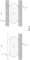
- FIG. 2 shows schematically different examples of configurations of the fluid processing device 10, in particular, of the pair of plate-like structures 11, 12. These configurations are respectively shown in cross-sectional views of the fluid processing device 10 in FIG. 2(a) and FIG. 2(b) .
- FIG. 2(a) shows a first configuration.
- the first plate-like structure 11 is configured for the functions or processing operations, i.e., for applying at least two of the heat 15, the magnetic field 16, and the light 17, to the one or more droplets 13 (and/or to detect the light 17 emitted from the droplets 13).
- the second plate-like structure 12 is non-functional in this first configuration, for instance, it may be a transparent sheet.
- the second plate-like structure 12 may be made of glass, and may be coated with a transparent oxide.
- the first plate-like structure 12 may be a TFT backplane with integrated circuits and/or integrated functional elements.
- the first configuration may be referred to as "single TFT backplane configuration".
- FIG. 2(b) shows a second configuration.
- both the first plate-like structure 11 and the second plate-like structure 12 are configured for the functions or processing operations, i.e., for applying the at least two of heat 15, magnetic field 16, and light 17, to the one or more droplets 13 (and/or to detect the light 17 emitted from the droplets 13).
- both the first and the second plate-like structure 11, 12 may be a TFT backplane with integrated circuits and/or integrated functional elements.
- the second configuration may be referred to as "double TFT backplane configuration".
- FIG. 3 shows schematically different examples of configurations of the fluid processing device 10, in particular, of the pair of plate-like structures 11, 12. These configurations are respectively shown in cross-sectional views of the fluid processing device 10 in FIG. 3(a) and FIG. 3(b) .
- the configurations in FIG. 3 are the same as shown in FIG. 2 .
- FIG. 3 also shows that the surface properties of the respective surfaces of the plate-like structures 11, 12 may be modified and/or tailored.
- the surface of any one or of both the plate-like structures 11, 12 can be coated, for instance, with surface coating layers that facilitate a reliable operation and reuse of the fluid processing device 10.
- These additional coating(s) maybe in the form of polymer or organic surfaces, and can, for example, prevent surface fouling, electrostatic charging, and dielectric breakdown of the underlying layers.
- FIG. 3 shows particularly a first coating layer 21 arranged on the first plate-like structure 11 (on its inner surface towards the droplet(s) 13) and a second coating layer 22 on the second plate-like structure 12 (also on its inner surface).
- These coating layers 21, 22 may be both applied, or may be applied individually.
- the first coating layer 21 may be different from the second coating layer 22, however, the coating layers 21, 22 may also be the same.
- Each coating layer 21, 22 may be or comprise a polymer layer and/or an organic layer.
- the coating layers 21, 22 may respectively be used in all the implementations of the plate-like structures 11, 12 of the fluid-processing device 10 discussed in this disclosure.
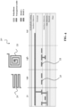
- FIG. 4 shows a cross-sectional view of an exemplary, functional plate-like structure 30, as it may be used in the fluid processing device 10, of FIG. 1 , for instance, in any configuration shown in FIG. 2 or FIG. 3 .
- the plate-like structure 30 may be the first plate-like structure 11 or the second plate-like structure 12 of the fluid processing device 10, or both.
- the plate-like structure 30 may be a TFT backplane.
- the plate-like structure 30 may comprise a substrate, which may include a plurality of layers.
- An example of the layers as shown includes: a glass layer; a base coating layer arranged on the glass layer; a gate dielectric layer arranged on the base coating layer; an interlayer dielectric arranged on the gate dielectric layer; an overcoat layer arranged on the interlayer dielectric; an insulator dielectric arranged on the overcoat layer; and a hydrophobic coating arranged on the insulator dielectric.
- the substrate may be similar to a substrate used in a conventional EWOD device, and is thus configured to manipulate the one or more droplets 13, which touch the hydrophobic coating surface, by electrowetting.
- the substrate may be provided with integrated circuits and/or functional elements.
- the exemplary plate-like structure 30 shown in FIG. 4 comprises the first sub-zone 14a, the second sub-zone 14b, and the third sub-zone 14c.
- a micro-heater 32 is embedded into the plate-like structure 30, for example, formed by a metal layer in the overcoat layer.
- the micro-heater 32 is configured to generate the heat 15, which is then experienced by the one or more droplets 13 on the surface of the plate-like structure 30.
- a metal coil 33 is embedded in the plate-like structure 30, for example, formed by two metal layers in the overcoat layer and the interlayer dielectric, respectively.
- the metal coil 33 is configured to generate the magnetic field 16, which is then experienced by the one or more droplets 13 on the surface of the plate-like structure 30.
- a transparent oxide may be arranged above the micro-heater 32 and the magnetic coil 33, respectively. Since the micro-heater 32 and the metal coil 33 are respectively embedded functional elements, the first sub-zone 14a and the second sub-zone 14b are provided in the so-called in-cell configuration.
- the exemplary plate-like structure 30 is transparent to light of at least one predetermined wavelength.
- a light emitting device configured to emit the light of the at least one predetermined wavelength may be arranged on or besides an outer surface of the plate-like structure 30 (e.g., besides or on the glass layer), and may emit light through the plate-like structure 30 onto the one or more droplets 13 and/or may detect light emitted by the one or more droplets 13 through the plate-like structure 30. Since the light emitting device would in this case be external of the plate-like structure 30, the third sub-zone 14c is in this case provided in the so-called add-on configuration.
- the exemplary plate-like structure 30 shown in FIG. 4 may further comprise a region 31, in which one or more TFT circuits may be embedded, wherein these circuits are configured for individually addressing and operating the functional sub-zones 14a, 14b, and 14c may be embedded.
- the circuits may be formed by one or more metal layers and polysilicon layers, which are embedded and structured in the substrate layers, e.g., as illustrated.
- FIG. 4 shows a possible cross-section of a functional part of the fluid processing device 10, particularly, illustrates a build-in of the different functional elements into the plate-like structure 30.
- These functional elements may include transparent EWOD electrodes, e.g., made of indium tin oxide (ITO) for performing droplet manipulation.
- these functional elements may include the micro-heater structures 32, may include the magnetic metal coil structures 33, and may include see-through sub-zones (e.g., ITO).
- the sub-zones 14a, 14b, 14c may be unit cells or pixels of a chip.
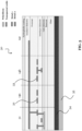
- FIG. 5 shows a cross-sectional view of another exemplary, functional plate-like structure 30, as it may be used in the fluid processing device 10, of FIG. 1 , for instance, in any configuration shown in FIG. 2 or FIG. 3 .
- the plate-like structure 30 may be the first plate-like structure 11 or the second plate-like structure 12 of the fluid processing device 10, or both.
- the plate-like structure 30 may be a TFT backplane.
- the plate-like structure 30 shown in FIG. 5 is based on the plate-like structure 30 shown in FIG. 4 , in particular, it may be identical except that it comprises either one or two further components, namely, at least one of a magnet 34 and a thermal interface 35.
- the magnet 34 may be a permanent magnet, for instance, may be implemented by a layer made of a magnetic material, which may be arranged adjacent to the substrate layers, in particular, adjacent to the glass layer.
- the magnet 34 may beneficially enhance magnetic forces in the fluid processing device 10. Magnetic force is proportional to the product of the magnetic field gradient and its magnitude.
- the magnetic force generated by the local magnetic elements, for example the coils 33, in the second sub-zone(s) 14b for applying the magnetic field 16 to the one or more droplets 13, can be enhanced with the presence of a global magnetic field provided by the magnet 34.
- the magnet 34 may be placed within the proximity of the second sub-zone(s) 14b, so as to create a magnetic field across the fluid processing device 10, wherein the magnetic field penetrates through at least droplets 13 arranged in the second sub-zone(s) 14b.
- a collection of multiple magnets can be used. These may be placed around the fluid processing device 10 to create a magnetic field that is preferably larger than 100 G.
- the magnetic field provided by the magnet 34 extends and covers the sub-zones 14b, in which the droplets 13 can be actuated by the magnetic elements, for instance, the coils 33.
- the thermal interface 35 may be controlled by a thermal controller.
- the thermal interface 35 may help to improve the performance of the fluid processing device 10, by providing a global thermal control across the fluid processing device 10, for instance, a global temperature within a temperature range of 4-60 °C.
- the benefit of such a global thermal control can be that the temperature of the fluid processing device 10, or specifically the droplet temperature, can be kept at a predetermined value.
- the predetermined value may, for example, be defined by the assay, the workflow, or the device characteristics.
- the global thermal control may create benefits in multiple ways. For example, some reagents are advantageously kept at a low temperature for optimal use.
- the fluid processing device 10 creates undesired heat, for example, due to current applied to its functional element, and thus the overall temperature of the fluid processing device 10 may increase during its operation beyond the safe limits of the assay.
- the global thermal control can be achieved using the thermal interface 35 on at least one of the substrate surfaces, which is not in contact with the droplets 13.
- This thermal interface 35 may be thermally linked to a heat pump configured to provide the necessary heat energy transfer to or from the fluid processing device 10, so as to achieve the (predetermined) target value of the temperature.
- the heat may be controlled by the thermal controller.
- the global thermal control may be further be optimized by using a single or a plurality of temperature sensors on the substrate, or in the vicinity of the substrate, so as to create a feedback loop for the thermal controller.
- FIG. 6 shows that also an in-cell configuration of the third sub-zone 14c is possible in a functional zone 14 of the fluid-processing device 10.
- a light emitting device 44 and a photodetector 43 may be respectively embedded in the first plate-like structure 11 and/or in the second plate-like structure 12.
- FIG. 6(a) shows particularly a so-called "across configuration" of the in-cell configuration of the third sub-zone 14c, wherein the integrated light emitting device 44 is arranged, for example, in the second plate-like structure 12, while the integrated photodetector 43 is arranged in the first plate-like structure 11 (could be vice versa).
- Each plate-like structure 11, 12 may also comprise an integrated optical filter 42, which may isolate light of interest and/or may filter out unwanted wavelengths.
- FIG. 6(b) shows particularly a so-called “same-side configuration" of the in-cell configuration of the third sub-zone 14c, wherein both the integrated light emitting device 44 and the integrated photodetector 43 are arranged in the same plate-like structure, for example, in the first plate-like structure 11 as shown (but could be the other plate-like structure 12 as well).
- Each plate-like structure 11, 12 may again comprise an integrated optical filter 42, which may isolate light of interest and/or may filter out unwanted wavelengths.
- FIG. 7 shows an example of the add-on configuration of the third sub-zone 14c, which may be used in the plate-like structure 30 of FIG. 4 or FIG. 5 .
- the second plate-like structure 12, and optionally also the first plate-like structure 11 are transparent to light 17 of at least one predetermined wavelength.
- a light emitting device 53 and a photodetector 54 are further respectively arranged on or besides an outer surface of the first plate-like structure 11 or of the second plate-like structure 12.
- the light emitting device 53 is configured to emit the light 17 of the at least one predetermined wavelength
- the photodetector 54 is configured to detect the light 17.
- FIG. 7(a) shows particularly an across configuration of the add-on configuration of the third sub-zone 14c, wherein the light emitting device 53 and the photodetector 54 are arranged on or besides different plate-like structures 11, 12, for example, the light emitting device 53 is arranged on or besides the second plate-like structure 12 - for instance with an optical filter 51 arranged in between the plate-like structure 12 and the light emitting device 53 - and the photodetector 54 is arranged on or besides the first plate-like structure 11 - for instance also with an optical filter 51 arranged in between the first plate-like structure 11 and the photodetector 54.
- the second plate-like structure 12 may be a glass that may be coated with a transparent oxide
- the first plate-like structure 11 may be a transparent TFT backplane, or at least a transparent region of such a TFT backplane.
- FIG. 7(b) shows particularly a same-side configuration of the add-on configuration of the third sub-zone 14c, wherein the light emitting device 53 and the photodetector 54 are arranged on or besides the same plate-like structure 11, 12, exemplarily the second plate-like structure 12.
- optical filters 51 may be arranged between the second plate-like structure 12 and, respectively, the photodetector 54 and the light emitting device 53.
- the second plate-like structure 12 maybe glass that maybe coated with transparent oxide.
- the first plate-like structure 11 may be a (e.g., non-transparent) TFT backplane.
- FIG. 8 shows an add-on configuration of a sub-zone, which could be the first sub-zone 14a or the second sub-zone 14b, or could be a special sub-zone configured to apply the heat 15 and the magnetic field 16.
- a sub-zone which could be the first sub-zone 14a or the second sub-zone 14b, or could be a special sub-zone configured to apply the heat 15 and the magnetic field 16.
- One or more heating elements 61 are respectively arranged on or besides the outer surface of the first plate-like structure 11 and/or of the second plate-like structure 12.
- one or more magnetic field generating elements 62 are respectively arranged on or besides an outer surface of the first plate-like structure 11 and/or of the second plate-like structure 12.
- FIG. 8(a) shows particular a double-side configuration of the add-on configuration of the sub-zone, wherein the heating elements 61 and the magnetic field generating elements 62 are arranged on or besides both plate-like structures 11, 12.
- the first plate-like structure may be a TFT backplane for EWOD
- the second plate-like structure 12 may be a glass that may be coated with a transparent oxide.
- the heating elements 61 and the magnetic field generating elements 62 may be arranged in an interleaved manner, e.g., arranged alternatingly along at least one direction.
- the functional elements 61 and 62 may be operated individually, or in sets, or all together.
- FIG. 8(b) shows particularly a single-side configuration of the add-on configuration of the sub-zone, wherein the heating elements 61 and the magnetic field generating elements 62 are arranged on or besides only one side of the plate-like structures 11, 12, for example, on or besides the first plate-like structure 11.
- the first plate-like structure 11 may be a TFT backplane for EWOD
- the second plate-like structure 12 may be a glass that may be coated with a transparent oxide.
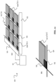
- FIG. 9 shows a fluid processing device 10 and fluid processing array 70 according to this disclosure, respectively, which can be used to implement different droplet processing workflows, particularly, longer and/or atypical workflows for library preparation.
- FIG. 9(a) shows the fluid-processing device 10.
- the fluid-processing device 10 is a (bio) chip, or is integrated into the chip.
- the chip comprises the multiple functional zones 14. Each functional zone 14 maybe or form a pixel of the chip.
- the functional zones 14 may all be identical and comprise each a first sub-zone 14a, a second sub-zone 14b, a third sub-zone 14c, and a fourth sub-zone identical to any one of the first sub-zone 14a, second sub-zone 14b, or third sub-zone 14c.
- FIG. 9(d) shows an example, according to which each functional zone 14 of the chip comprises two first sub-zones 14a (in other words, the fourth sub-zone is identical to the first sub-zone 14a).
- the chip may have and area of about 2 cm x 2 cm, and may comprise an EWOD on TFT display as the first plate-like structure 11 (e.g., it may be similar to the substrate shown in FIG. 4 or FIG. 5 ).
- This chip may be divided in up to 400 individually controllable functional zones 14, which enables a very flexible digital microfluidics platform.
- the chip may further comprise an overlay 71 for EWOD as the second plate-like structure 12. That is, each functional zone 14 and each sub-zone of the chip is covered with the overlay 71, as illustrated in FIG. 9(d) .
- the first plate-likes structure 11 may be referred to as "bottom", and the second plate-like structure as "top” overlay (see FIG. 9(b) ).
- sample library preparation can refer to any combination of biochemical reactions, which transform input samples (e.g., nucleic acids) to a configuration that can be read by a sequencer, and is not limited to a specific sequencing chemistry.
- the chip's flexibility originates from the pixel-level implementation of the four essential functionalities, which are needed to deploy library preparation protocols and workflows. These four functionalities include providing the heat 15 (pixel heat), providing the magnetic field 16 (pixel bead), providing the light (pixel light), and manipulating the droplets 13 (pixel drop). The functionalities may be distributed evenly across the chip, thus ensuring full flexibility in programming any library preparation workflow for discrete samples on the chip.
- Pixel drop utilizes the electrowetting principle (or EWOD) to move, split, combine and mix the droplets 13.
- Pixel heat may be needed to allow isothermal enzymatic incubation reactions, as well as temperature cycling enabled Polymerase Chain Reaction (PCR).
- Pixel bead may allow DNA-bound paramagnetic beads to be concentrated, and as such can allow for a buffer exchange as well as up concentration of the bound DNA.
- Pixel light may allow for tracking of the droplets 13, as well as for colorimetric or fluorometric analysis, for example, for performing quality controls during sample preparation.
- FIG. 9(c) shows the fluid processing array 70, which is in this case a panel and comprises a plurality of the fluid processing devices 10.
- the fluid processing array 70 comprises a plurality of the chips (e.g., in a range of 200-1000 chips, for example, 400 chips), and each chip is one of the fluid processing devices 10 or at least comprises at least one of the fluid processing devices 10.
- the multiple chips or fluid processing devices 10 can be arranged in rows and/or columns to form the fluid processing array 70, in order to allow for more complex or elaborate sample processing protocols. Parallelization may allow the processing of up to 400 different samples simultaneously.
- Input of the one or more droplets 13, e.g. comprising samples and reagents, as well as the output of the prepared library are beneficial for the efficient implementation of assay on the chip or array 70.
- Two possible are envisioned for accordingly providing input ports and output ports.
- an acoustic-based method may be used.
- input ports and/or output ports may comprise one or more PMUTs.
- This technology would allow the acoustic inter-plate transfer of below microliter reagent volumes.
- the power of acoustics for nanoliter scale handling of the fluid has already been proven by commercial solutions.
- a precise feedback control of a pipette through projected capacitive sensing can allow contact dispensing of below microliter reagent volumes.
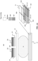
- FIG. 10 shows an example of a fluid-processing device 10, which may be a chip as shown in FIG. 9 and may have a similar pixel or unit cell as shown in FIG. 9(d) , however, without any third zone 14c.
- the fluid processing device 10 is shown in same-side configuration, and is similar to the fluid processing device 10 shown in FIG. 7(b) .
- a light emitting device 53 and a photodetector 54 are arranged on or besides the second plate-like structure 12.
- Optical filters 51 may be arranged between the second plate-like structure 12 and, respectively, the photodetector 54 and the light emitting device 53.
- FIG. 11 shows an example implementation for individually addressing the sub-zones 14a/b/c of a fluid processing system 90 according to this disclosure.
- the fluid processing system 90 is particularly shown in FIG. 11(a) and comprises at least one fluid processing device 10 or at least one fluid processing array 70, and further comprises a control unit 91, for instance, a microcontroller.
- FIG. 11(a) shows that the fluid processing device 10 or array 70 has a matrix (columns and rows) arrangement of the sub-zones 14a/b/c, and comprises row addressing lines 92 and column addressing lines 93, which are respectively interfaced with the control unit 91.
- switches 95 are provided, one switch 95 for each of the sub-zones 14a/b/c.
- the control unit 91 may use the addressing lines 92, 93 and the switches 95 to individually address each sub-zone 14a/b/c.
- FIG. 11(b) shows one of the sub-zones 14a/b/c in an enlarged view.
- the sub-zone comprises a gate line 94 that is connected to the column addressing line 93, and comprise a data line 96 that is connected to the row addressing line 92.
- Each sub-zone 14a/b/c may be identically connected by such a gate line 94 and data line 96.
- the switch 95 may be connected to gate line 94 and data line 96.
- control unit 91 can be configured to control an operation of one or more of the sub-zones 14a/b/c of the fluid processing device 10 or array 70, so as to apply heat 15, a magnetic field 16, and/or light 17, in any order to one or more droplets 13.
- control unit 91 can be configured to control, at the same time, an operation of any two or more functional zones 14 of the fluid processing device 10 or array 70, so as to respectively apply heat 15, a magnetic field 16 and/or light 17, in any order, to one or more first droplets 13 and to one or more second droplets 13, i.e., simultaneously to different droplets 13 potentially in different functional zones 14.
- control unit 91 can be configured to control a movement of one or more droplets 13 to one or more functional zones 14 of the fluid processing device 10 or array 70.
- control unit 91 can be configured to control a movement of one or more droplets 13 to one or more fluid processing devices 10 of the fluid processing system 90.
- the control unit 91 may comprise a processor or processing circuitry (not shown) configured to perform, conduct or initiate the various operations of the control unit 91 described above.
- the processing circuitry may comprise hardware and/or the processing circuitry may be controlled by software.
- the hardware may comprise analog circuitry or digital circuitry, or both analog and digital circuitry.
- the digital circuitry may comprise components such as application-specific integrated circuits (ASICs), field-programmable arrays (FPGAs), digital signal processors (DSPs), or multi-purpose processors.
- the control unit 91 may further comprise memory circuitry, which stores one or more instruction(s) that can be executed by the processor or by the processing circuitry, in particular under control of the software.
- the memory circuitry may comprise a non-transitory storage medium storing executable software code which, when executed by the processor or the processing circuitry, causes the various operations of the control unit 91 to be performed.
- the processing circuitry comprises one or more processors and a non-transitory memory connected to the one or more processors.
- the non-transitory memory may carry executable program code which, when executed by the one or more processors, causes the control unit 91 to perform, conduct or initiate the operations or methods described herein.
- FIG. 12 shows a method 100 according to this disclosure.
- the method 100 may be used for fluid processing, and can be performed by the fluid processing device 10.
- the method comprises a step 101 of manipulating one or more droplets 13 of a fluid or liquid, which are located between a first plate-like structure 11 and a second plate-like structure 12, by electrowetting.
- the method 100 further comprises a step 102 of applying, by respectively operating one or more sub-zones 14a/b/c of a plurality of functional zones 14 of the fluid processing device 10, at least two of heat 15, a magnetic field 16, and light 17, in any order, to the one or more droplets 13.
- the steps 101 and 102 may be performed in any order, and may be performed one or more times.
- a "Nextera" DNA library preparation workflow could be implemented by the fluid processing device 10 and method 100.
- a tagmentation step could be performed, whereby a sample (including DNA), a tagmentation enzyme, and a buffer are introduced on the fluid processing device 10 as one or more droplets 13, which may be mixed and heated (with heat 15 in a first sub-zone 14a), which allows the included DNA to fragment and at the same time be tagged in a one-step reaction.
- a purification step could be performed using magnetic beads (and a magnetic field 16 in a second sub-zone 14b), which allows for a buffer exchange, whereby the tagmented DNA bound on the beads may be later re-suspended.
- PCR reagents could be subsequently introduced on the fluid processing device 10, and may be mixed with the re-suspended DNA, after which temperature cycling may be performed (using heat 15 in a first sub-zone 14a) to allow adaptor ligation and library amplification.
- Another bead-based purification step (with a magnetic field 16 in a second sub-zone 14b) may allow the used PCR reagents to be washed away from the amplified library DNA and re-suspended to the desired concentration in a sequencer-compatible buffer.
- an improved device 10 which may be used for automated manipulation and processing of one or more droplets 13, for example, containing at least one sample.
- the device 10 may implement a sample library preparation workflow, in particular, may perform any on-demand processing of the droplets 13 and may implement different kinds of library preparation workflows.
Landscapes
- Chemical & Material Sciences (AREA)
- Health & Medical Sciences (AREA)
- Dispersion Chemistry (AREA)
- General Health & Medical Sciences (AREA)
- Clinical Laboratory Science (AREA)
- Chemical Kinetics & Catalysis (AREA)
- Analytical Chemistry (AREA)
- Hematology (AREA)
- Life Sciences & Earth Sciences (AREA)
- Biochemistry (AREA)
- Molecular Biology (AREA)
- Physical Or Chemical Processes And Apparatus (AREA)
Abstract
The present disclosure relates to devices for manipulating droplets of a fluid by electrowetting. The disclosure provides a fluid processing device comprising a first plate-like structure and a second plate-like structure, which are configured to manipulate one or more droplets located between the first and the second plate-like structure by electrowetting. The fluid processing device comprises a plurality of functional zones, and each functional zone comprises at least two of a first sub-zone for applying heat to the one or more droplets, a second sub-zone for applying a magnetic field to the one or more droplets, and a third sub-zone for providing light onto and/or detecting light emitted by the one or more droplets.
Description
- The present disclosure relates to devices for manipulating one or more droplets of a fluid or liquid by electrowetting. The disclosure provides such a device, which is also adapted to perform one or more processing operations on the one or more droplets. These processing operations comprise a treatment of the one or more droplets by heat, light, and/or magnetic field. The droplet processing may be used for implementing a workflow, for instance, a sample library preparation workflow.
- Library preparation of samples is an indispensable step for next generation sequencing. The process of library preparation may entail an adaptation of the samples, so that they are compatible with downstream sequencing chemistry. Library preparation protocols usually consist of many steps of processing the sample, which require expensive reagents and significant hands-on-time.
- Different types of sequencing chemistries have allowed a diversification in research questions that can be addressed by next generation sequencing, and have also diversified the possibilities in sample input and library preparation protocols. As a consequence, however, genomic core facilities need to constantly optimize existing workflows, and are under pressure to handle diverse requests from different customers. Library preparation is becoming the bottleneck of sequencing workflows, and by extension of the next generation sequencing ecosystem. In fact, the library preparation may account for up to 50% of the sequencing lead times.
- In an example of an automated library preparation, which may be implemented in core facilities, multiple samples are processed in batches. Certain instruments used for the processing are run only, when the core facility received a sufficient number of samples. In this way, the instruments (e.g., pipetting robots) may be run in a cost-effective manner. As a consequence, however, on-demand sample processing or different library preparation workflows is typically not supported. In addition, the batching of the samples lengthens the processing lead times substantially.
- The present disclosure is based further on the following considerations, which preceded the solutions provided in this disclosure.
- Conventional electrowetting devices, like electrowetting on dielectric (EWOD) devices, can be used to manipulate one or more droplets, e.g., comprising samples. Further, the electrowetting devices may be equipped with fixed magnetic, thermal, and fluorescence detection zones, which may be implemented at the instrument level. Thus, the electrowetting devices could be used for an automated library preparation. However, at any one time, each zone can support processing of the droplets with only one set of operating parameters (e.g., one fixed temperature). As a consequence, only one workflow at a time can effectively be implement using the electrowetting device.
- In view of the above, an objective of this disclosure is to provide an improved device for implementing an automated manipulation and processing of one or more droplets. A particular objective is to enable the implementation of automated library preparation workflows with the device. For example, an objective is to enable customized and on-demand processing of droplets comprising samples, and different kinds of sample library preparation workflows. Another objective is to enable the simultaneous implementation of the workflows, in particular, if they are initiated at different times.
- These and other objectives are achieved by the solutions described in the independent claims. Advantageous implementations are further described in the dependent claims.
- A first aspect of this disclosure provides a fluid processing device comprising: a first plate-like structure and a second plate-like structure configured to manipulate one or more droplets, which are located between the first and the second plate-like structure, by electrowetting, wherein the fluid processing device comprises a plurality of functional zones, and each functional zone comprises at least two of: a first sub-zone for applying heat to the one or more droplets; second sub-zone for applying a magnetic field to the one or more droplets; and a third sub-zone for providing light onto and/or detecting light emitted by the one or more droplets.
- The fluid processing device of the first aspect is able to process the one or more droplets of a fluid or liquid, and further to apply different processing operations to the one or more droplets. These operations comprise a treatment of the one or more droplets by heat, and/or light, and/or magnetic field, and/or comprise optical measurements of the one or more droplets. Notably, the fluid may be a sample or may include a sample, in particular, a droplet may comprise at least one sample. In this case, the fluid processing device may process the droplets for the purpose of implementing a sample library preparation workflow. A sample may be an analyte sample (e.g., blood), or may also include other chemical fluids (e.g., reagents), which may be captured in the droplet(s).
- Due to the plurality of functional zones, and particularly the two or more sub-zones of each functional zone, the fluid processing device of the first aspect may implement customized and on-demand processing of the one or more droplets. Thus, the device may implement different kinds of library preparation workflows. For example, the device may simultaneously implement different kinds of workflows, wherein these workflows may be initiated at the same time or at different times. The at least two sub-zones of each functional zone may, in order to achieve an efficient droplet processing, be addressable individually (e.g., via an active selection matrix bitline and wordline layer).
- Notably, a sub-zone could potentially also include two functions. For instance, a first sub-zone or a second sub-zone could be configured to provide both heat and magnetic field.
- Any plate-like structure of the fluid processing device may be a substrate or may comprise a substrate, wherein one or more functional elements for respectively providing heat, and/or a magnetic field, and/or light, may be integrated into the substrate. The substrate may comprises multiple layers, which are used to embed and structure these integrated functional elements, for instance, by means of forming metal layers, depositing oxides, forming dielectric layers, or similar processing operations of an integrated process flow.
- Any plate-like structure of the fluid processing device may also be a glass sheet or may comprise a glass sheet, or may be or comprise a similar transparent element, on or besides which one or more external functional elements for respectively providing the heat, and/or the magnetic field, and/or the light, may be arranged or attached.
- Together, the first plate-like structure and the second plate-like structure of the fluid processing device may form a fluidic chamber for guiding and/or holding, and manipulating the one or more droplets.
- Manipulating the one or more droplets by electrowetting may comprise at least one of the following: moving the one or more droplets within a functional zone (e.g., from one sub-zone to another sub-zone of the functional zone); moving the one or more droplets into or out of a functional zone (e.g., from or to another functional zone); splitting at least one of the one or more droplets (e.g., in more smaller droplets); and combining or mixing two or more droplets (e.g., into a larger droplet). Notably, the terms "fluid" and "liquid" may be used interchangeably in this disclosure. The fluid/liquid may be water, or a water-chemistry-mix, or a suitable carrier liquid for samples, or may be a sample like blood.
- The reliability of manipulating the one or more droplets by electrowetting - also referred to as electrowetting actuation or droplet actuation - may be improved by employing an electrical and/or optical sensing mechanism. For example, a particular sub-zone of any functional zone of the fluid-processing device may be allocated to the sensing mechanism, wherein a droplet state of a droplet can be sensed and detected with the sensing mechanism in the particular sub-zone. The droplet state can, for instance, simply be the presence or absence of the droplet in the functional zone, particularly, in the particular sub-zone. A network of sensors could be used to estimate a droplet volume, a droplet shape, etc. The sensing mechanism can be carried out via resistance, capacitance, or optical density measurements, as an example.
- Accordingly, in an implementation of the fluid processing device, one or more functional zones of the fluid processing device respectively comprise a sensing sub-zone for sensing a droplet state of at least one droplet.
- In an implementation of the fluid processing device, each sensing sub-zone comprises one or more sensors configured to detect the droplet state. The one or more sensors may comprise electrical sensors and/or optical sensors.
- In an implementation of the fluid processing device, each sub-zone has an area in a range of 1e-6 cm2 - 1 cm2, or in a range of 5e-5 cm2 - 5e-4 cm2.
- The sub-zones can thus be small, for example, can be smaller than, or in an example implementation at least ten times smaller than, the size of a typical droplet, in order to be small enough to process single droplets. The functional zones, which comprises such small sub-zones, may be individual pixels of a (bio) chip comprising multiple pixels.
- In an implementation of the fluid processing device, the functional zones are identical.
- For instance, the size of all the functional zones may be identical. Moreover, in any functional zone of the fluid processing device, the size of all the sub-zones of this functional zone and/or the arrangement of the sub-zones may be identical. Thus, the fluid processing device may comprise a repeating pattern of functional zones and sub-zones. An advantage thereof is that the fluid processing device, particularly its functional zones, is easier to manufacture.
- In another implementation of the fluid processing device, a pattern of the functional zones is identical but may be reversely arranged in at least two functional zones. In another implementation of the fluid processing device, the functional zones are distinct from each other, or at least two functional zones may be distinct from each other.
- In an implementation of the fluid processing device, in the second sub-zone, a metal coil is embedded in the first plate-like structure or in the second plate-like structure, the metal coil being configured to generate a magnetic field.
- Embedding the metal coil in such a manner is referred to as an "in-cell configuration" of the second sub-zone, as no external magnetic field generating element is required. An advantage of this is that the magnetic field can be generated nearer to the one or more droplets than with an external magnetic field generating element.
- In an implementation of the fluid processing device, in the first sub-zone, a micro-heater is embedded in the first plate-like structure or in the second plate-like structure.
- Embedding the micro-heater in such a manner is referred to as an "in-cell configuration" of the first sub-zone, as no external heating element is required. Embedding functional elements into one or both plate-like structures allows making the fluid processing device more compact, and facilitates its integration into a chip or into an array of fluid processing devices.
- In the above implementations, if the fluid processing device has a first zone and a second zone, the magnetic coil and the micro-heater may be embedded in the same plate-like structure (i.e., they may be arranged on the same side) or may be embedded in different plate-like structures (i.e., they may be arranged on opposite sides). In addition, more than one metal coil and/or more than one micro-heater may be, respectively, embedded into the first plate-like structure or into the second plate-like structure, or into both plate-like structures.
- In an implementation of the fluid processing device: in the second sub-zone, one or more magnetic field generating elements are respectively arranged on or besides an outer surface of the first plate-like structure or of the second plate-like structure; and/or in the first sub-zone, one or more heating elements are respectively arranged on or besides the outer surface of the first plate-like structure or of the second plate-like structure.
- This implementation is referred to as an "add-on configuration" of the first sub-zone and/or second sub-zone, as external functional elements may be used. The magnetic field generating elements and the heating elements may be arranged on the same side of the two plate-like structures, or maybe arranged on opposite sides of the two plate-like structures.
- In an implementation of the fluid processing device, in the third sub-zone, a light emitting device and a photodetector are respectively embedded in the first plate-like structure or in the second plate-like structure.
- Embedding these optical elements in such a manner is referred to as an "in-cell configuration" of the third sub-zone. The light emitting device (e.g., a light emitting diode) and the photodetector (e.g., a CMOS sensor) may be embedded in the same plate-like structure or in different plate-like structures. The light emitting device may be configured to emit light of at least one wavelength, and the photodetector may detect light in at least that at least one wavelength and optionally other wavelengths.
- In an implementation of the fluid processing device, in the third sub-zone: the first plate-like structure and/or the second plate-like structure is transparent to light of at least one predetermined wavelength; and a light emitting device, which is configured to emit the light of the at least one predetermined wavelength, and a photodetector are respectively arranged on or besides an outer surface of the first plate-like structure or of the second plate-like structure.
- This implementation is referred to as an "add-on configuration" of the third sub-zone, as external functional elements may be used.
- In an implementation of the fluid processing device, at least one of the first sub-zone, the second sub-zone, and the third sub-zone is implemented in the in-cell configuration. In another implementation of the fluid processing device, at least two of the first sub-zone, the second sub-zone, and the third sub-zone are implemented in the in-cell configuration. In these implementations, the sub-zones that are not implemented in the in-cell configuration may be implemented in the add-on configuration. The in-cell configuration has the general advantage that no external components are needed and that a more compact design can be achieved. In another implementation of the fluid processing device, all three sub-zones may be implemented either in the in-cell configuration or in the add-on configuration.
- In an implementation of the fluid processing device, at least one of the functional zones comprises the first sub-zone, the second sub-zone, and the third sub-zone, and comprises a fourth sub-zone, which is identical to either the first sub-zone, the second sub-zone, or the third sub-zone.
- For instance, a combination of two first sub-zones, one second sub-zone, and one third sub-zone is possible. Another example is to combine one first sub-zone, two second sub-zones, and one third sub-zone into the functional zone.
- In an implementation, the fluid processing device further comprises one or more magnets arranged next to the first plate-like structure and/or the second plate-like structure, wherein the one or more magnets are configured to generate a magnetic field that penetrates the one or more droplets when they are located between the first and the second plate-like structure.
- Each magnet may be a permanent magnet. A magnet may be implemented by a magnetic layer. Multiple magnets may be arranged next to at least one the first plate-like structure and the second plate-like structure. The one or more magnets may be located on any one side of the two plate-like structures, or on both sides. The one or more magnets may be located above or beneath the two plate-like structures, respectively.
- Notably, "next to" in this respect may mean that the one or more magnets are arranged directly next to the first and/or second plate-like structure, for instance, adjacent to the first and/or the second plate-like structure. This may maximize the magnetic field induced forces. However, "next to" may also mean that the one or more magnets are not arranged directly next to the first and/or second plate-like structure, but at least in a certain proximity to the first and/or second plate-like structure that allows the magnetic field to penetrate the one or more droplets when they are located between the first and the second plate-like structure. For instance, "next to" may mean at a distance to the first and/or the second plate-like structure that is less than a few centimeters, for example, less than 10 cm, or less than 5 cm, or less than 2 cm. The one or more magnets may also be movable relative to the first and the second plate-like structure, for instance by means of a mechanical actuation mechanism, so that they can be brought to be arranged "next to" the first and/or second plate-like structure on demand.
- In an implementation, the fluid processing device further comprises a thermal interface arranged next to the first plate-like structure and/or the second plate-like structure, wherein the thermal interface is configured to provide a predetermined temperature across at least the first plate-like structure and the second plate-like structure.
- The "next to" in this respect, i.e. related to the thermal interface, is interpreted in the same way as the "next to" related to the one or more magnets described above.
- The thermal interface is thus configured to provide the predetermined temperature across droplets located between the plate-like structures. The thermal interface may be implemented as a layer. A thermal interface layer and a magnetic layer forming the magnet may be arranged one on the other next to the first and/or second plate-like structure. The thermal interface may be configured to generate heat or cooling itself, or may be provided with thermal energy to further distribute the heat or cooling.
- In an implementation, the fluid processing device further comprises a heat pump configured to provide a thermal energy transfer from the thermal interface or to the thermal interface.
- The heat pump may transfer the thermal energy to or from a heat sink or a heat source, or the like. The heat pump can thus be thermally connected to the thermal interface.
- In an implementation, the fluid processing device further comprises a thermal controller configured to control the thermal interface and/or the heat pump.
- For instance, the thermal interface may be controlled by the thermal controller to change temperature. As another example, a heat energy transfer of the heat pump may be increased or decreased by the thermal controller.
- In an implementation, the fluid processing device further comprises: one or more input ports, each input port being configured to receive the one or more droplets and to provide the one or more droplets to between the first plate-like structure and the second plate-like structure; and/or one or more output ports, each output port being configured to eject the one or more droplets from between the first plate-like structure and the second plate-like structure or from the fluid processing device.
- In an implementation of the fluid processing device, the one or more input ports and/or the one or more output ports comprise respectively one or more piezoelectric micromachined ultrasonic transducers (PMUTs).
- In an implementation, the fluid processing device comprises or is integrated with a fluidic distribution network.
- The fluidic distribution network may (fluidically) link the one or more input ports and the one or more output ports of the fluid processing device, respectively, to an external fluidic interface. The fluidic interface may be accessible, for example, via pipettes. The fluidic distribution network may be a part of the fluid processing device, or may be external the fluid processing device.
- The fluidic distribution network may allow connecting one external facing port to one or more input ports of the fluid processing device in a controlled way. For instance, in a controlled way may mean that a pressure and/or a volume quantity of fluid over the connection is measurable and adjustable. This can be useful when a reagent or a sample material needs to be metered and distributed to multiple locations on the fluid processing device, for instance to perform parallel operations. The fluidic distribution network may be realized by or in plastic, glass, or another material, and may contain at least one of: a fluidic channel, a fluidic chamber, a valve, and another component to enable fluid transfer.
- In an implementation, the fluid processing device is or comprise an EWOD device, and/or comprises an array of thin film transistors for applying droplet electrowetting.
- In an implementation, the fluid processing device further comprises or is connected to controller circuitry, which is configured to control the fluid processing device.
- The fluid-processing device may be controlled by the controller circuitry to perform predefined operations. One or more predefined operations, or respective instructions for performing the predefined operations, may be stored in a local memory of the fluid processing device, or in an external memory. For example, the controller circuitry may control the fluid processing device to combine different functional zones and/or sub-zones, for example, in dependence of a reagent or a sample volume of the current workflow. The controller circuitry may also interact with a sensor or a sensor network of the fluid processing device, in order to adapt the operations of the fluid processing device in the presence of, for example, local failures of zones and/or sub-zones. For instance, the controller circuitry may control the fluid processing device to divert operations to respectively other zones and/or sub-zones. This may particularly be done, if a local failure is detected.
- In an implementation, the fluid processing device further comprises one or more programmable separators, which are configured to separate the plurality of functional zones into a plurality of regions, wherein each region comprises at least one functional zone.
- The one or more separators may thus be configured to split the area of the device that comprises the functional zones into multiple regions. These regions are local regions, which are physically separated from each other by the respective separator(s). This separation may prevent material interchange in the form of droplet transport or diffusion via a medium. The one or more separators may be further helpful to minimize or eliminate potential cross-contamination between different samples or workflows running (e.g. in parallel) in different regions of the fluid processing device. Each separator may be implemented by a phase change material, which may be transported as droplets or pre-printed on any plate-like structure in the liquid phase. A reversible or non-reversible phase change may be induced via heat activation, or by a chemical reaction between multiple materials, so as to induce solidification and a barrier (separator) formation between different regions of the fluid processing device. This may be done on demand and flexibly as desired.
- A second aspect of this disclosure provides a fluid processing array comprising a plurality of fluid processing devices according to the first aspect or any implementation thereof.
- The fluid processing array may specifically be a sample processing array configured to perform a sample processing workflow. The fluid processing array may be used for (sample) library preparation, and could be included in a cartridge for library preparation.
- In an implementation of the fluid processing array, the fluid processing array is a chip or a panel; or the fluid processing array comprises a plurality of chips, each chip comprising at least one of the fluid processing devices.
- Any chip may be a bio chip, and may comprise multiple unit cells or pixels, which may correspond to the multiple functional zones of a fluid processing device. A panel may be a planar arrangement of multiple such chips or fluid processing devices.
- A third aspect of this disclosure provides fluid processing system comprising at least one fluid processing device according to the first aspect or any implementation thereof, or comprising the fluid processing array of the second aspect or any implementation thereof, wherein the fluid processing system further comprises a control unit configured to address and control individually each sub-zone of each functional zone in the fluid processing system.
- The fluid processing system may be a sample processing system configured to perform a sample processing workflow, for example, a sample library preparation workflow.
- Since each sub-zone in the fluid processing system is individually addressable, a variety of such workflows can be performed on the one or more droplets, wherein each workflow may include multiple processing operations.
- The control unit may be or may comprise the above-mentioned controller circuitry.
- In an implementation of the fluid processing system, the control unit is configured to: control an operation of one or more sub-zones of any functional zone of the fluid processing device or of the fluid processing array, so as to apply heat, a magnetic field, and/or light, in any order, to one or more droplets; and/or control at the same time an operation of any two or more functional zones of the fluid processing device or of the fluid processing array, so as to respectively apply heat, a magnetic field and/or light, in any order, to one or more first droplets and to one or more second droplets.
- In this way, different library preparation workflows can be implemented subsequently or simultaneously with high efficiency.
- In an implementation of the fluid processing system, the control unit is further configured to: control a movement of one or more droplets to one or more functional zones of the fluid processing device or of the fluid processing array; and/or control a movement of one or more droplets to one or more fluid processing devices of the fluid processing system.
- A fourth aspect of this disclosure provides a computer program comprising instructions which, when the program is executed by the control unit (e.g., a processor therefor), causes the fluid processing system to perform the above actions, or to perform the method of the fifth aspect, or to implement a droplet processing workflow.
- A fifth aspect of this disclosure provides a method for fluid processing, the method comprising: manipulating one or more droplets arranged between a first plate-like structure and a second plate-like structure by electrowetting; and applying, by respectively operating one or more sub-zones of a plurality of functional zones of the pair of plate-like structures, at least two of heat, a magnetic field, and light, in any order, to the one or more droplets.
- The method of the fifth aspect achieves the same advantages as the fluid processing device of the first aspect, and may be extended by respective implementations as described above for the fluid processing device of the first aspect.
- The above described aspects and implementations are explained in the following description of embodiments with respect to the enclosed drawings:
- FIG. 1
- shows schematically a fluid processing device according to this disclosure.
- FIG. 2
- shows different configurations of the two plate-like structures of a fluid processing device according to this disclosure.
- FIG. 3
- shows different configurations of the two plate-like structures of a fluid processing device according to this disclosure, wherein the two-plate like structures comprise surface coating layers.
- FIG. 4
- shows an example of a plate-like structure with embedded functional elements for a fluid processing device according to this disclosure.
- FIG. 5
- shows an example of a plate-like structure with embedded functional elements and with further magnetic and/or thermal elements for a fluid processing device according to this disclosure.
- FIG. 6
- shows an in-cell configuration of a third sub-zone of a fluid processing device according to this disclosure.
- FIG. 7
- shows an add-on configuration of a third sub-zone of a fluid processing device according to this disclosure
- FIG. 8
- shows an add-on configuration of first and/or second sub-zones of a fluid processing device according to this disclosure.
- FIG. 9
- shows a fluid processing array and a fluid processing device according to this disclosure, which may be used for implementing atypical or longer droplet processing workflows.
- FIG. 10
- shows an example of a functional zone of a fluid processing device according to this disclosure, wherein the functional zone is designed without a third sub-zone.
- FIG. 11
- shows an example implementation for individually addressing sub-zones in a fluid processing system according to this disclosure.
- FIG. 12
- shows a method for processing a fluid according to this disclosure.
-
FIG. 1 shows afluid processing device 10 according to this disclosure. Thefluid processing device 10 is configured to manipulate and process one ormore droplets 13 of a fluid or liquid. The fluid orliquid processing device 10 may be a sample processing device, and the fluid or liquid may accordingly comprise one or more samples, for example, each droplet may comprise at least one sample. A sample may be an analyte sample (e.g., blood or other bodily fluid), or may be any other chemical fluid (e.g., a reagent), which may be captured in the droplet. The droplets may be of a fluid or liquid suitable for containing the one or more samples. - The
fluid processing device 10 comprises a first plate-like structure 11 and a second plate-like structure 12, which are configured to receive the one ormore droplets 13 in the space between the plate-like structures, and to hold or guide thedroplets 13 in between. The plate-like structures more droplets 13, when thedroplets 13 are located between the plate-like structures more droplets 13 may comprise moving the one ormore droplets 13, and/or splitting one ormore droplets 13, and/or combining one ormore droplets 13. In particular, the plate-like structures more droplets 13 by electrowetting. The plate-like structures like structures more droplets 13 are arranged, held and/or guided between the two surfaces, i.e., both surfaces may touch the one ormore droplets 13. At least one of the plate-like structures - The
fluid processing device 10 comprises a plurality offunctional zones 14, wherein different regions of the pair of plate-like structures functional zones 14. Eachfunctional zone 14 may be configured to perform at least two functions or processing operations on the one ormore droplets 13. To this end, eachfunctional zone 14 has multiple sub-zones, wherein each sub-zone may be used for one of the processing operations. Thefunctional zones 14 of thefluid processing device 10 may all be identical. For instance, eachfunctional zone 14 may have the same size, and/or may have the same number of sub-zones, and/or may have the same types of sub-zones, and/or may have the same layout or arrangement of sub-zones. - In particular, each
functional zone 14 comprises at least two of afirst sub-zone 14a, asecond sub-zone 14b and athird sub-zone 14c (shown exemplarily inFIG. 1 , not necessarily belonging to the same functional zone 14). Each of these sub-zones 14a, 14b, and 14c may have an area in a range of 1e-6 cm2 - 1 cm2, for example, an area in a range of 5e-5 cm2 - 5e-4 cm2. Thefirst sub-zone 14a is for applyingheat 15 to the one ormore droplets 13, and may thus be referred to as a "heat sub-zone". Thesecond sub-zone 14b is for applying amagnetic field 16 to the one ormore droplets 13, and may thus be referred to as a "magnetic sub-zone" Thethird sub-zone 14c is for providing light 17 onto the one ormore droplets 13, and/or for detecting light 17 emitted by the one ormore droplets 13, and may thus be referred to as a "light sub-zone". -
FIG. 2 shows schematically different examples of configurations of thefluid processing device 10, in particular, of the pair of plate-like structures fluid processing device 10 inFIG. 2(a) and FIG. 2(b) . -
FIG. 2(a) shows a first configuration. In this first configuration, the first plate-like structure 11 is configured for the functions or processing operations, i.e., for applying at least two of theheat 15, themagnetic field 16, and the light 17, to the one or more droplets 13 (and/or to detect the light 17 emitted from the droplets 13). The second plate-like structure 12 is non-functional in this first configuration, for instance, it may be a transparent sheet. For instance, the second plate-like structure 12 may be made of glass, and may be coated with a transparent oxide. The first plate-like structure 12 may be a TFT backplane with integrated circuits and/or integrated functional elements. The first configuration may be referred to as "single TFT backplane configuration". -
FIG. 2(b) shows a second configuration. In this second configuration, both the first plate-like structure 11 and the second plate-like structure 12 are configured for the functions or processing operations, i.e., for applying the at least two ofheat 15,magnetic field 16, and light 17, to the one or more droplets 13 (and/or to detect the light 17 emitted from the droplets 13). For instance, both the first and the second plate-like structure -
FIG. 3 shows schematically different examples of configurations of thefluid processing device 10, in particular, of the pair of plate-like structures fluid processing device 10 inFIG. 3(a) and FIG. 3(b) . The configurations inFIG. 3 are the same as shown inFIG. 2 . -
FIG. 3 also shows that the surface properties of the respective surfaces of the plate-like structures like structures fluid processing device 10. These additional coating(s) maybe in the form of polymer or organic surfaces, and can, for example, prevent surface fouling, electrostatic charging, and dielectric breakdown of the underlying layers. -
FIG. 3 shows particularly afirst coating layer 21 arranged on the first plate-like structure 11 (on its inner surface towards the droplet(s) 13) and asecond coating layer 22 on the second plate-like structure 12 (also on its inner surface). These coating layers 21, 22 may be both applied, or may be applied individually. Thefirst coating layer 21 may be different from thesecond coating layer 22, however, the coating layers 21, 22 may also be the same. Eachcoating layer like structures device 10 discussed in this disclosure. -
FIG. 4 shows a cross-sectional view of an exemplary, functional plate-like structure 30, as it may be used in thefluid processing device 10, ofFIG. 1 , for instance, in any configuration shown inFIG. 2 orFIG. 3 . The plate-like structure 30 may be the first plate-like structure 11 or the second plate-like structure 12 of thefluid processing device 10, or both. The plate-like structure 30 may be a TFT backplane. The plate-like structure 30 may comprise a substrate, which may include a plurality of layers. An example of the layers as shown includes: a glass layer; a base coating layer arranged on the glass layer; a gate dielectric layer arranged on the base coating layer; an interlayer dielectric arranged on the gate dielectric layer; an overcoat layer arranged on the interlayer dielectric; an insulator dielectric arranged on the overcoat layer; and a hydrophobic coating arranged on the insulator dielectric. The substrate may be similar to a substrate used in a conventional EWOD device, and is thus configured to manipulate the one ormore droplets 13, which touch the hydrophobic coating surface, by electrowetting. - In addition, the substrate may be provided with integrated circuits and/or functional elements. For example, the exemplary plate-
like structure 30 shown inFIG. 4 comprises thefirst sub-zone 14a, thesecond sub-zone 14b, and thethird sub-zone 14c. In thefirst sub-zone 14a, a micro-heater 32 is embedded into the plate-like structure 30, for example, formed by a metal layer in the overcoat layer. The micro-heater 32 is configured to generate theheat 15, which is then experienced by the one ormore droplets 13 on the surface of the plate-like structure 30. In thesecond sub-zone 14c, ametal coil 33 is embedded in the plate-like structure 30, for example, formed by two metal layers in the overcoat layer and the interlayer dielectric, respectively. Themetal coil 33 is configured to generate themagnetic field 16, which is then experienced by the one ormore droplets 13 on the surface of the plate-like structure 30. A transparent oxide may be arranged above the micro-heater 32 and themagnetic coil 33, respectively. Since the micro-heater 32 and themetal coil 33 are respectively embedded functional elements, thefirst sub-zone 14a and thesecond sub-zone 14b are provided in the so-called in-cell configuration. - In the
third sub-zone 14c, the exemplary plate-like structure 30 is transparent to light of at least one predetermined wavelength. Thus, for example, a light emitting device configured to emit the light of the at least one predetermined wavelength may be arranged on or besides an outer surface of the plate-like structure 30 (e.g., besides or on the glass layer), and may emit light through the plate-like structure 30 onto the one ormore droplets 13 and/or may detect light emitted by the one ormore droplets 13 through the plate-like structure 30. Since the light emitting device would in this case be external of the plate-like structure 30, thethird sub-zone 14c is in this case provided in the so-called add-on configuration. - The exemplary plate-
like structure 30 shown inFIG. 4 may further comprise aregion 31, in which one or more TFT circuits may be embedded, wherein these circuits are configured for individually addressing and operating the functional sub-zones 14a, 14b, and 14c may be embedded. The circuits may be formed by one or more metal layers and polysilicon layers, which are embedded and structured in the substrate layers, e.g., as illustrated. - In sum,
FIG. 4 shows a possible cross-section of a functional part of thefluid processing device 10, particularly, illustrates a build-in of the different functional elements into the plate-like structure 30. These functional elements may include transparent EWOD electrodes, e.g., made of indium tin oxide (ITO) for performing droplet manipulation. Further, these functional elements may include themicro-heater structures 32, may include the magneticmetal coil structures 33, and may include see-through sub-zones (e.g., ITO). The sub-zones 14a, 14b, 14c may be unit cells or pixels of a chip. -
FIG. 5 shows a cross-sectional view of another exemplary, functional plate-like structure 30, as it may be used in thefluid processing device 10, ofFIG. 1 , for instance, in any configuration shown inFIG. 2 orFIG. 3 . The plate-like structure 30 may be the first plate-like structure 11 or the second plate-like structure 12 of thefluid processing device 10, or both. The plate-like structure 30 may be a TFT backplane. - The plate-
like structure 30 shown inFIG. 5 is based on the plate-like structure 30 shown inFIG. 4 , in particular, it may be identical except that it comprises either one or two further components, namely, at least one of amagnet 34 and athermal interface 35. - The
magnet 34 may be a permanent magnet, for instance, may be implemented by a layer made of a magnetic material, which may be arranged adjacent to the substrate layers, in particular, adjacent to the glass layer. Themagnet 34 may beneficially enhance magnetic forces in thefluid processing device 10. Magnetic force is proportional to the product of the magnetic field gradient and its magnitude. The magnetic force generated by the local magnetic elements, for example thecoils 33, in the second sub-zone(s) 14b for applying themagnetic field 16 to the one ormore droplets 13, can be enhanced with the presence of a global magnetic field provided by themagnet 34. To this end, themagnet 34 may be placed within the proximity of the second sub-zone(s) 14b, so as to create a magnetic field across thefluid processing device 10, wherein the magnetic field penetrates through atleast droplets 13 arranged in the second sub-zone(s) 14b. Instead of the shownsingle magnet 34, also a collection of multiple magnets can be used. These may be placed around thefluid processing device 10 to create a magnetic field that is preferably larger than 100 G. Preferably, the magnetic field provided by the magnet 34 (or the magnets) extends and covers the sub-zones 14b, in which thedroplets 13 can be actuated by the magnetic elements, for instance, thecoils 33. - The
thermal interface 35 may be controlled by a thermal controller. Thethermal interface 35 may help to improve the performance of thefluid processing device 10, by providing a global thermal control across thefluid processing device 10, for instance, a global temperature within a temperature range of 4-60 °C. The benefit of such a global thermal control can be that the temperature of thefluid processing device 10, or specifically the droplet temperature, can be kept at a predetermined value. The predetermined value may, for example, be defined by the assay, the workflow, or the device characteristics. The global thermal control may create benefits in multiple ways. For example, some reagents are advantageously kept at a low temperature for optimal use. It is also possible that thefluid processing device 10 creates undesired heat, for example, due to current applied to its functional element, and thus the overall temperature of thefluid processing device 10 may increase during its operation beyond the safe limits of the assay. The global thermal control can be achieved using thethermal interface 35 on at least one of the substrate surfaces, which is not in contact with thedroplets 13. Thisthermal interface 35 may be thermally linked to a heat pump configured to provide the necessary heat energy transfer to or from thefluid processing device 10, so as to achieve the (predetermined) target value of the temperature. The heat may be controlled by the thermal controller. The global thermal control may be further be optimized by using a single or a plurality of temperature sensors on the substrate, or in the vicinity of the substrate, so as to create a feedback loop for the thermal controller. -
FIG. 6 shows that also an in-cell configuration of thethird sub-zone 14c is possible in afunctional zone 14 of the fluid-processingdevice 10. In this case, in thethird sub-zone 14c, alight emitting device 44 and aphotodetector 43 may be respectively embedded in the first plate-like structure 11 and/or in the second plate-like structure 12. -
FIG. 6(a) shows particularly a so-called "across configuration" of the in-cell configuration of thethird sub-zone 14c, wherein the integratedlight emitting device 44 is arranged, for example, in the second plate-like structure 12, while theintegrated photodetector 43 is arranged in the first plate-like structure 11 (could be vice versa). Each plate-like structure optical filter 42, which may isolate light of interest and/or may filter out unwanted wavelengths. -
FIG. 6(b) shows particularly a so-called "same-side configuration" of the in-cell configuration of thethird sub-zone 14c, wherein both the integratedlight emitting device 44 and theintegrated photodetector 43 are arranged in the same plate-like structure, for example, in the first plate-like structure 11 as shown (but could be the other plate-like structure 12 as well). Each plate-like structure optical filter 42, which may isolate light of interest and/or may filter out unwanted wavelengths. -
FIG. 7 shows an example of the add-on configuration of thethird sub-zone 14c, which may be used in the plate-like structure 30 ofFIG. 4 orFIG. 5 . InFIG. 7 the second plate-like structure 12, and optionally also the first plate-like structure 11, are transparent to light 17 of at least one predetermined wavelength. Alight emitting device 53 and aphotodetector 54 are further respectively arranged on or besides an outer surface of the first plate-like structure 11 or of the second plate-like structure 12. Thelight emitting device 53 is configured to emit the light 17 of the at least one predetermined wavelength, and thephotodetector 54 is configured to detect the light 17. -
FIG. 7(a) shows particularly an across configuration of the add-on configuration of thethird sub-zone 14c, wherein thelight emitting device 53 and thephotodetector 54 are arranged on or besides different plate-like structures light emitting device 53 is arranged on or besides the second plate-like structure 12 - for instance with anoptical filter 51 arranged in between the plate-like structure 12 and the light emitting device 53 - and thephotodetector 54 is arranged on or besides the first plate-like structure 11 - for instance also with anoptical filter 51 arranged in between the first plate-like structure 11 and thephotodetector 54. The second plate-like structure 12 may be a glass that may be coated with a transparent oxide, and the first plate-like structure 11 may be a transparent TFT backplane, or at least a transparent region of such a TFT backplane. -
FIG. 7(b) shows particularly a same-side configuration of the add-on configuration of thethird sub-zone 14c, wherein thelight emitting device 53 and thephotodetector 54 are arranged on or besides the same plate-like structure like structure 12. Again,optical filters 51 may be arranged between the second plate-like structure 12 and, respectively, thephotodetector 54 and thelight emitting device 53. Like inFIG. 7(a) , the second plate-like structure 12 maybe glass that maybe coated with transparent oxide. The first plate-like structure 11 may be a (e.g., non-transparent) TFT backplane. -
FIG. 8 shows an add-on configuration of a sub-zone, which could be thefirst sub-zone 14a or thesecond sub-zone 14b, or could be a special sub-zone configured to apply theheat 15 and themagnetic field 16. One ormore heating elements 61 are respectively arranged on or besides the outer surface of the first plate-like structure 11 and/or of the second plate-like structure 12. Further, one or more magneticfield generating elements 62 are respectively arranged on or besides an outer surface of the first plate-like structure 11 and/or of the second plate-like structure 12. -
FIG. 8(a) shows particular a double-side configuration of the add-on configuration of the sub-zone, wherein theheating elements 61 and the magneticfield generating elements 62 are arranged on or besides both plate-like structures like structure 12 may be a glass that may be coated with a transparent oxide. Theheating elements 61 and the magneticfield generating elements 62 may be arranged in an interleaved manner, e.g., arranged alternatingly along at least one direction. Thefunctional elements -
FIG. 8(b) shows particularly a single-side configuration of the add-on configuration of the sub-zone, wherein theheating elements 61 and the magneticfield generating elements 62 are arranged on or besides only one side of the plate-like structures like structure 11. The first plate-like structure 11 may be a TFT backplane for EWOD, and the second plate-like structure 12 may be a glass that may be coated with a transparent oxide. -
FIG. 9 shows afluid processing device 10 andfluid processing array 70 according to this disclosure, respectively, which can be used to implement different droplet processing workflows, particularly, longer and/or atypical workflows for library preparation. -
FIG. 9(a) shows the fluid-processingdevice 10. In this example, the fluid-processingdevice 10 is a (bio) chip, or is integrated into the chip. The chip comprises the multiplefunctional zones 14. Eachfunctional zone 14 maybe or form a pixel of the chip. - The
functional zones 14 may all be identical and comprise each afirst sub-zone 14a, asecond sub-zone 14b, athird sub-zone 14c, and a fourth sub-zone identical to any one of thefirst sub-zone 14a,second sub-zone 14b, or third sub-zone 14c.FIG. 9(d) shows an example, according to which eachfunctional zone 14 of the chip comprises twofirst sub-zones 14a (in other words, the fourth sub-zone is identical to the first sub-zone 14a). - The chip may have and area of about 2 cm x 2 cm, and may comprise an EWOD on TFT display as the first plate-like structure 11 (e.g., it may be similar to the substrate shown in
FIG. 4 orFIG. 5 ). This chip may be divided in up to 400 individually controllablefunctional zones 14, which enables a very flexible digital microfluidics platform. The chip may further comprise anoverlay 71 for EWOD as the second plate-like structure 12. That is, eachfunctional zone 14 and each sub-zone of the chip is covered with theoverlay 71, as illustrated inFIG. 9(d) . The first plate-likesstructure 11 may be referred to as "bottom", and the second plate-like structure as "top" overlay (seeFIG. 9(b) ). - The chip provides a new microfluidic structure, which allows for a very flexible processing of the one or
more droplets 13, and thus flexible implementation of sample library preparation workflows. Notably, the term "sample library preparation" can refer to any combination of biochemical reactions, which transform input samples (e.g., nucleic acids) to a configuration that can be read by a sequencer, and is not limited to a specific sequencing chemistry. - The chip's flexibility originates from the pixel-level implementation of the four essential functionalities, which are needed to deploy library preparation protocols and workflows. These four functionalities include providing the heat 15 (pixel heat), providing the magnetic field 16 (pixel bead), providing the light (pixel light), and manipulating the droplets 13 (pixel drop). The functionalities may be distributed evenly across the chip, thus ensuring full flexibility in programming any library preparation workflow for discrete samples on the chip. Pixel drop utilizes the electrowetting principle (or EWOD) to move, split, combine and mix the
droplets 13. Pixel heat may be needed to allow isothermal enzymatic incubation reactions, as well as temperature cycling enabled Polymerase Chain Reaction (PCR). Pixel bead may allow DNA-bound paramagnetic beads to be concentrated, and as such can allow for a buffer exchange as well as up concentration of the bound DNA. Pixel light may allow for tracking of thedroplets 13, as well as for colorimetric or fluorometric analysis, for example, for performing quality controls during sample preparation. -
FIG. 9(c) shows thefluid processing array 70, which is in this case a panel and comprises a plurality of thefluid processing devices 10. In particular, thefluid processing array 70 comprises a plurality of the chips (e.g., in a range of 200-1000 chips, for example, 400 chips), and each chip is one of thefluid processing devices 10 or at least comprises at least one of thefluid processing devices 10. The multiple chips orfluid processing devices 10 can be arranged in rows and/or columns to form thefluid processing array 70, in order to allow for more complex or elaborate sample processing protocols. Parallelization may allow the processing of up to 400 different samples simultaneously. - Input of the one or
more droplets 13, e.g. comprising samples and reagents, as well as the output of the prepared library are beneficial for the efficient implementation of assay on the chip orarray 70. Two possible are envisioned for accordingly providing input ports and output ports. In a first solution, an acoustic-based method may be used. For instance, input ports and/or output ports may comprise one or more PMUTs. This technology would allow the acoustic inter-plate transfer of below microliter reagent volumes. The power of acoustics for nanoliter scale handling of the fluid has already been proven by commercial solutions. In a second solution, a precise feedback control of a pipette through projected capacitive sensing can allow contact dispensing of below microliter reagent volumes. -
FIG. 10 shows an example of a fluid-processingdevice 10, which may be a chip as shown inFIG. 9 and may have a similar pixel or unit cell as shown inFIG. 9(d) , however, without anythird zone 14c. In particular, thefluid processing device 10 is shown in same-side configuration, and is similar to thefluid processing device 10 shown inFIG. 7(b) . Alight emitting device 53 and aphotodetector 54 are arranged on or besides the second plate-like structure 12.Optical filters 51 may be arranged between the second plate-like structure 12 and, respectively, thephotodetector 54 and thelight emitting device 53. -
FIG. 11 shows an example implementation for individually addressing the sub-zones 14a/b/c of afluid processing system 90 according to this disclosure. Thefluid processing system 90 is particularly shown inFIG. 11(a) and comprises at least onefluid processing device 10 or at least onefluid processing array 70, and further comprises acontrol unit 91, for instance, a microcontroller.FIG. 11(a) shows that thefluid processing device 10 orarray 70 has a matrix (columns and rows) arrangement of the sub-zones 14a/b/c, and comprisesrow addressing lines 92 andcolumn addressing lines 93, which are respectively interfaced with thecontrol unit 91. Further, switches 95 are provided, oneswitch 95 for each of the sub-zones 14a/b/c. Thecontrol unit 91 may use the addressinglines switches 95 to individually address each sub-zone 14a/b/c.FIG. 11(b) shows one of the sub-zones 14a/b/c in an enlarged view. The sub-zone comprises agate line 94 that is connected to thecolumn addressing line 93, and comprise adata line 96 that is connected to therow addressing line 92. Eachsub-zone 14a/b/c may be identically connected by such agate line 94 anddata line 96. Theswitch 95 may be connected togate line 94 anddata line 96. - As an example, the
control unit 91 can be configured to control an operation of one or more of the sub-zones 14a/b/c of thefluid processing device 10 orarray 70, so as to applyheat 15, amagnetic field 16, and/or light 17, in any order to one ormore droplets 13. - As another example, the
control unit 91 can be configured to control, at the same time, an operation of any two or morefunctional zones 14 of thefluid processing device 10 orarray 70, so as to respectively applyheat 15, amagnetic field 16 and/or light 17, in any order, to one or morefirst droplets 13 and to one or moresecond droplets 13, i.e., simultaneously todifferent droplets 13 potentially in differentfunctional zones 14. - As another example, the
control unit 91 can be configured to control a movement of one ormore droplets 13 to one or morefunctional zones 14 of thefluid processing device 10 orarray 70. - As another example, the
control unit 91 can be configured to control a movement of one ormore droplets 13 to one or morefluid processing devices 10 of thefluid processing system 90. - The
control unit 91 may comprise a processor or processing circuitry (not shown) configured to perform, conduct or initiate the various operations of thecontrol unit 91 described above. The processing circuitry may comprise hardware and/or the processing circuitry may be controlled by software. The hardware may comprise analog circuitry or digital circuitry, or both analog and digital circuitry. The digital circuitry may comprise components such as application-specific integrated circuits (ASICs), field-programmable arrays (FPGAs), digital signal processors (DSPs), or multi-purpose processors. Thecontrol unit 91 may further comprise memory circuitry, which stores one or more instruction(s) that can be executed by the processor or by the processing circuitry, in particular under control of the software. For instance, the memory circuitry may comprise a non-transitory storage medium storing executable software code which, when executed by the processor or the processing circuitry, causes the various operations of thecontrol unit 91 to be performed. In one embodiment, the processing circuitry comprises one or more processors and a non-transitory memory connected to the one or more processors. The non-transitory memory may carry executable program code which, when executed by the one or more processors, causes thecontrol unit 91 to perform, conduct or initiate the operations or methods described herein. -
FIG. 12 shows amethod 100 according to this disclosure. Themethod 100 may be used for fluid processing, and can be performed by thefluid processing device 10. The method comprises astep 101 of manipulating one ormore droplets 13 of a fluid or liquid, which are located between a first plate-like structure 11 and a second plate-like structure 12, by electrowetting. Themethod 100 further comprises astep 102 of applying, by respectively operating one or more sub-zones 14a/b/c of a plurality offunctional zones 14 of thefluid processing device 10, at least two ofheat 15, amagnetic field 16, and light 17, in any order, to the one ormore droplets 13. Thesteps - For instance, a "Nextera" DNA library preparation workflow could be implemented by the
fluid processing device 10 andmethod 100. At first, a tagmentation step could be performed, whereby a sample (including DNA), a tagmentation enzyme, and a buffer are introduced on thefluid processing device 10 as one ormore droplets 13, which may be mixed and heated (withheat 15 in a first sub-zone 14a), which allows the included DNA to fragment and at the same time be tagged in a one-step reaction. Next, a purification step could be performed using magnetic beads (and amagnetic field 16 in a second sub-zone 14b), which allows for a buffer exchange, whereby the tagmented DNA bound on the beads may be later re-suspended. PCR reagents could be subsequently introduced on thefluid processing device 10, and may be mixed with the re-suspended DNA, after which temperature cycling may be performed (usingheat 15 in a first sub-zone 14a) to allow adaptor ligation and library amplification. Another bead-based purification step (with amagnetic field 16 in a second sub-zone 14b) may allow the used PCR reagents to be washed away from the amplified library DNA and re-suspended to the desired concentration in a sequencer-compatible buffer. - In summary of this disclosure, an
improved device 10 is provided, which may be used for automated manipulation and processing of one ormore droplets 13, for example, containing at least one sample. Thedevice 10 may implement a sample library preparation workflow, in particular, may perform any on-demand processing of thedroplets 13 and may implement different kinds of library preparation workflows. - In the claims as well as in the description of this disclosure, the word "comprising" does not exclude other elements or steps and the indefinite article "a" or "an" does not exclude a plurality. A single element may fulfill the functions of several entities or items recited in the claims. The mere fact that certain measures are recited in the mutual different dependent claims does not indicate that a combination of these measures cannot be used in an advantageous implementation.
Claims (15)
- A fluid processing device (10) comprising:a first plate-like structure (11) and a second plate-like structure (12) configured to manipulate one or more droplets (13), which are located between the first and the second plate-like structure (11, 12), by electrowetting,wherein the fluid processing device (10) comprises a plurality of functional zones (14), and each functional zone (14) comprises at least two of:a first sub-zone (14a) for applying heat (15) to the one or more droplets (13);a second sub-zone (14b) for applying a magnetic field (16) to the one or more droplets (13); anda third sub-zone (14c) for providing light (17) onto and/or detecting light (17) emitted by the one or more droplets (13).
- The fluid processing device (10) according to claim 1, whereineach sub-zone (14a, 14b, 14c) has an area in a range of 1e-6 cm2 - 1 cm2 or in a range of 5e-5 cm2 - 5e-4 cm2; and/orthe functional zones (14) are identical.
- The fluid processing device (10) according to claim 1 or 2, wherein in the second sub-zone (14b), a metal coil (33) is embedded in the first plate-like structure (11) or in the second plate-like structure (12), the metal coil (33) being configured to generate a magnetic field (16).
- The fluid processing device (10) according to one of the claims 1 to 3, wherein in the first sub-zone (14a), a micro-heater (32) is embedded in the first plate-like structure (11) or in the second plate-like structure (12).
- The fluid processing device (10) according to claim 1 or 2, wherein:in the second sub-zone (14b), one or more magnetic field generating elements (62) are respectively arranged on or besides an outer surface of the first plate-like structure (11) or of the second plate-like structure (12); and/orin the first sub-zone (14a), one or more heating elements (61) are respectively arranged on or besides the outer surface of the first plate-like structure (11) or of the second plate-like structure (12).
- The fluid processing device (10) according to one of the claims 1 to 5, wherein in the third sub-zone (14c), a light emitting device (44) and a photodetector (43) are respectively embedded in the first plate-like structure (11) or in the second plate-like structure (12).
- The fluid processing device (10) according to one of the claims 1 to 5, wherein in the third sub-zone (14c):the first plate-like structure (11) and/or the second plate-like structure (12) is transparent to light of at least one predetermined wavelength; anda light emitting device (53), which is configured to emit the light of the at least one predetermined wavelength, and a photodetector (54) are respectively arranged on or besides an outer surface of the first plate-like structure (11) or of the second plate-like structure (12).
- The fluid processing device (10) according to one of the claims 1 to 7, wherein at least one of the functional zones (14) comprises the first sub-zone (14a), the second sub-zone (14b), and the third sub-zone (14c), and comprises a fourth sub-zone, which is identical to either the first sub-zone (14a), the second sub-zone (14b), or the third sub-zone (14c).
- The fluid processing device (10) according to one of the claims 1 to 8, further comprising:one or more magnets (34) arranged next to the first plate-like structure (11) and/or the second plate-like structure (12), and configured to generate a magnetic field that penetrates the one or more droplets (13) when they are located between the first and the second plate-like structure (11,12); and/ora thermal interface (35) arranged next to the first plate-like structure (11) and/or the second plate-like structure (12), and configured to provide a predetermined temperature across at least the first plate-like structure (11) and the second plate-like structure (12).
- The fluid processing device (10) according to one of the claims 1 to 9, further comprising:one or more input ports, each input port being configured to receive the one or more droplets (13) and to provide the one or more droplets (13) to between the first plate-like structure (11) and the second plate-like structure (12); and/orone or more output ports, each output port being configured to eject the one or more droplets (13) from between the first plate-like structure (11) and the second plate-like structure (12) or from the fluid processing device (10).
- A fluid processing array (70) comprising a plurality of fluid processing devices (10) according to one of the claims 1 to 10.
- The fluid processing array (70) according to claim 11, wherein:the fluid processing array (70) is a chip or a panel; orthe fluid processing array (70) comprises a plurality of chips, each chip comprising at least one of the fluid processing devices (10).
- A fluid processing system (90) comprising at least one fluid processing device (10) according to one of the claims 1 to 10 or comprising the fluid processing array (70) of claim 11 or 12, wherein the fluid processing system (90) further comprises:
a control unit (91) configured to address and control individually each sub-zone (14a, 14b, 14c) of each functional zone (14) in the fluid processing system (90). - The fluid processing system (90) according to claim 13, wherein the control unit (91) is configured to:control an operation of one or more sub-zones (14a, 14b, 14c) of any functional zone (14) of the fluid processing device (10) or of the fluid processing array (70), so as to apply heat (15), a magnetic field (16), and/or light (17), in any order, to one or more droplets (13); and/orcontrol at the same time an operation of any two or more functional zones (14) of the fluid processing device (10) or of the fluid processing array (70), so as to respectively apply heat (15), a magnetic field (16) and/or light (17), in any order, to one or more first droplets (13) and to one or more second droplets (13).
- The fluid processing system (90) according to claim 14, wherein the control unit (91) is further configured to:control a movement of one or more droplets (13) to one or more functional zones (14) of the fluid processing device (10) or of the fluid processing array (70); and/orcontrol a movement of one or more droplets (13) to one or more fluid processing devices (10) of the fluid processing system (90).
Applications Claiming Priority (1)
| Application Number | Priority Date | Filing Date | Title |
|---|---|---|---|
| EP23176639 | 2023-06-01 |
Publications (1)
| Publication Number | Publication Date |
|---|---|
| EP4474054A1 true EP4474054A1 (en) | 2024-12-11 |
Family
ID=86657509
Family Applications (1)
| Application Number | Title | Priority Date | Filing Date |
|---|---|---|---|
| EP24177544.4A Pending EP4474054A1 (en) | 2023-06-01 | 2024-05-23 | A fluid processing device for manipulating and processing droplets |
Country Status (2)
| Country | Link |
|---|---|
| US (1) | US20240399370A1 (en) |
| EP (1) | EP4474054A1 (en) |
Cited By (1)
| Publication number | Priority date | Publication date | Assignee | Title |
|---|---|---|---|---|
| EP4737004A1 (en) * | 2024-10-31 | 2026-05-06 | Imec VZW | A fluid processing device for processing droplets |
Citations (3)
| Publication number | Priority date | Publication date | Assignee | Title |
|---|---|---|---|---|
| WO2019226919A1 (en) * | 2018-05-23 | 2019-11-28 | Miroculus Inc. | Control of evaporation in digital microfluidics |
| WO2021041709A1 (en) * | 2019-08-27 | 2021-03-04 | Volta Labs, Inc. | Methods and systems for droplet manipulation |
| US20230110598A1 (en) * | 2021-10-08 | 2023-04-13 | Cytesi, Inc. | Microfluidic apparatus |
-
2024
- 2024-05-23 EP EP24177544.4A patent/EP4474054A1/en active Pending
- 2024-05-31 US US18/680,062 patent/US20240399370A1/en active Pending
Patent Citations (3)
| Publication number | Priority date | Publication date | Assignee | Title |
|---|---|---|---|---|
| WO2019226919A1 (en) * | 2018-05-23 | 2019-11-28 | Miroculus Inc. | Control of evaporation in digital microfluidics |
| WO2021041709A1 (en) * | 2019-08-27 | 2021-03-04 | Volta Labs, Inc. | Methods and systems for droplet manipulation |
| US20230110598A1 (en) * | 2021-10-08 | 2023-04-13 | Cytesi, Inc. | Microfluidic apparatus |
Cited By (2)
| Publication number | Priority date | Publication date | Assignee | Title |
|---|---|---|---|---|
| EP4737004A1 (en) * | 2024-10-31 | 2026-05-06 | Imec VZW | A fluid processing device for processing droplets |
| WO2026093267A1 (en) * | 2024-10-31 | 2026-05-07 | Imec Vzw | A fluid processing device for processing droplets |
Also Published As
| Publication number | Publication date |
|---|---|
| US20240399370A1 (en) | 2024-12-05 |
Similar Documents
| Publication | Publication Date | Title |
|---|---|---|
| JP5266208B2 (en) | Droplet treatment system | |
| EP2548646B1 (en) | Cartridge and system for manipulating samples in liquid droplets | |
| Chabert et al. | Automated microdroplet platform for sample manipulation and polymerase chain reaction | |
| EP2358906B2 (en) | System and instrument for processing biological samples and manipulating liquids having biological samples | |
| CN105008052B (en) | Droplet Size Manipulation in Digital Microfluidic Systems | |
| US11772093B2 (en) | Methods of mechanical microfluidic manipulation | |
| US9857332B2 (en) | System for manipulating samples in liquid droplets | |
| US20060166261A1 (en) | PCR and hybridization methods utilizing electrostatic transportation and devices therefor | |
| Lifesciences et al. | Microfluidics in commercial applications; an industry perspective | |
| CA2982671A1 (en) | Multiplexed, continuous-flow, droplet-based platform for high-throughput genetic detection | |
| US11047776B2 (en) | Liquid sending method using sample processing chip and liquid sending device for sample processing chip | |
| US8367976B2 (en) | Laser heating of aqueous samples on a micro-optical-electro-mechanical system | |
| JP4307074B2 (en) | Method and system for performing biological, chemical or biochemical protocols in a continuous flow | |
| US20240399370A1 (en) | Fluid processing device for manipulating and processing droplets | |
| EP2943279B1 (en) | System for manipulating samples in liquid droplets | |
| WO2022053824A1 (en) | Composite top plate for magnetic and temperature control in a digital microfluidic device | |
| EP4737004A1 (en) | A fluid processing device for processing droplets | |
| Houchaimi et al. | Digital Microfluidics Automation of Oligonucleotide Assemblies | |
| HK1061258A (en) | Microfluidic system for analyzing nucleic acids |
Legal Events
| Date | Code | Title | Description |
|---|---|---|---|
| PUAI | Public reference made under article 153(3) epc to a published international application that has entered the european phase |
Free format text: ORIGINAL CODE: 0009012 |
|
| STAA | Information on the status of an ep patent application or granted ep patent |
Free format text: STATUS: THE APPLICATION HAS BEEN PUBLISHED |
|
| AK | Designated contracting states |
Kind code of ref document: A1 Designated state(s): AL AT BE BG CH CY CZ DE DK EE ES FI FR GB GR HR HU IE IS IT LI LT LU LV MC ME MK MT NL NO PL PT RO RS SE SI SK SM TR |
|
| STAA | Information on the status of an ep patent application or granted ep patent |
Free format text: STATUS: REQUEST FOR EXAMINATION WAS MADE |
|
| 17P | Request for examination filed |
Effective date: 20250610 |