EP4474047A1 - Exhaust gas purification catalyst - Google Patents
Exhaust gas purification catalyst Download PDFInfo
- Publication number
- EP4474047A1 EP4474047A1 EP23766704.3A EP23766704A EP4474047A1 EP 4474047 A1 EP4474047 A1 EP 4474047A1 EP 23766704 A EP23766704 A EP 23766704A EP 4474047 A1 EP4474047 A1 EP 4474047A1
- Authority
- EP
- European Patent Office
- Prior art keywords
- exhaust gas
- base material
- layer
- nox storage
- catalyst
- Prior art date
- Legal status (The legal status is an assumption and is not a legal conclusion. Google has not performed a legal analysis and makes no representation as to the accuracy of the status listed.)
- Granted
Links
Images
Classifications
-
- B—PERFORMING OPERATIONS; TRANSPORTING
- B01—PHYSICAL OR CHEMICAL PROCESSES OR APPARATUS IN GENERAL
- B01J—CHEMICAL OR PHYSICAL PROCESSES, e.g. CATALYSIS OR COLLOID CHEMISTRY; THEIR RELEVANT APPARATUS
- B01J37/00—Processes, in general, for preparing catalysts; Processes, in general, for activation of catalysts
- B01J37/02—Impregnation, coating or precipitation
- B01J37/024—Multiple impregnation or coating
- B01J37/0244—Coatings comprising several layers
-
- B—PERFORMING OPERATIONS; TRANSPORTING
- B01—PHYSICAL OR CHEMICAL PROCESSES OR APPARATUS IN GENERAL
- B01J—CHEMICAL OR PHYSICAL PROCESSES, e.g. CATALYSIS OR COLLOID CHEMISTRY; THEIR RELEVANT APPARATUS
- B01J23/00—Catalysts comprising metals or metal oxides or hydroxides, not provided for in group B01J21/00
- B01J23/38—Catalysts comprising metals or metal oxides or hydroxides, not provided for in group B01J21/00 of noble metals
- B01J23/40—Catalysts comprising metals or metal oxides or hydroxides, not provided for in group B01J21/00 of noble metals of the platinum group metals
- B01J23/46—Ruthenium, rhodium, osmium or iridium
- B01J23/464—Rhodium
-
- B—PERFORMING OPERATIONS; TRANSPORTING
- B01—PHYSICAL OR CHEMICAL PROCESSES OR APPARATUS IN GENERAL
- B01D—SEPARATION
- B01D53/00—Separation of gases or vapours; Recovering vapours of volatile solvents from gases; Chemical or biological purification of waste gases, e.g. engine exhaust gases, smoke, fumes, flue gases, aerosols
- B01D53/34—Chemical or biological purification of waste gases
- B01D53/92—Chemical or biological purification of waste gases of engine exhaust gases
- B01D53/94—Chemical or biological purification of waste gases of engine exhaust gases by catalytic processes
- B01D53/9445—Simultaneously removing carbon monoxide, hydrocarbons or nitrogen oxides making use of three-way catalysts [TWC] or four-way-catalysts [FWC]
- B01D53/945—Simultaneously removing carbon monoxide, hydrocarbons or nitrogen oxides making use of three-way catalysts [TWC] or four-way-catalysts [FWC] characterised by a specific catalyst
-
- B—PERFORMING OPERATIONS; TRANSPORTING
- B01—PHYSICAL OR CHEMICAL PROCESSES OR APPARATUS IN GENERAL
- B01J—CHEMICAL OR PHYSICAL PROCESSES, e.g. CATALYSIS OR COLLOID CHEMISTRY; THEIR RELEVANT APPARATUS
- B01J23/00—Catalysts comprising metals or metal oxides or hydroxides, not provided for in group B01J21/00
- B01J23/38—Catalysts comprising metals or metal oxides or hydroxides, not provided for in group B01J21/00 of noble metals
- B01J23/40—Catalysts comprising metals or metal oxides or hydroxides, not provided for in group B01J21/00 of noble metals of the platinum group metals
-
- B—PERFORMING OPERATIONS; TRANSPORTING
- B01—PHYSICAL OR CHEMICAL PROCESSES OR APPARATUS IN GENERAL
- B01J—CHEMICAL OR PHYSICAL PROCESSES, e.g. CATALYSIS OR COLLOID CHEMISTRY; THEIR RELEVANT APPARATUS
- B01J23/00—Catalysts comprising metals or metal oxides or hydroxides, not provided for in group B01J21/00
- B01J23/38—Catalysts comprising metals or metal oxides or hydroxides, not provided for in group B01J21/00 of noble metals
- B01J23/40—Catalysts comprising metals or metal oxides or hydroxides, not provided for in group B01J21/00 of noble metals of the platinum group metals
- B01J23/42—Platinum
-
- B—PERFORMING OPERATIONS; TRANSPORTING
- B01—PHYSICAL OR CHEMICAL PROCESSES OR APPARATUS IN GENERAL
- B01J—CHEMICAL OR PHYSICAL PROCESSES, e.g. CATALYSIS OR COLLOID CHEMISTRY; THEIR RELEVANT APPARATUS
- B01J23/00—Catalysts comprising metals or metal oxides or hydroxides, not provided for in group B01J21/00
- B01J23/38—Catalysts comprising metals or metal oxides or hydroxides, not provided for in group B01J21/00 of noble metals
- B01J23/40—Catalysts comprising metals or metal oxides or hydroxides, not provided for in group B01J21/00 of noble metals of the platinum group metals
- B01J23/44—Palladium
-
- B—PERFORMING OPERATIONS; TRANSPORTING
- B01—PHYSICAL OR CHEMICAL PROCESSES OR APPARATUS IN GENERAL
- B01J—CHEMICAL OR PHYSICAL PROCESSES, e.g. CATALYSIS OR COLLOID CHEMISTRY; THEIR RELEVANT APPARATUS
- B01J35/00—Catalysts, in general, characterised by their form or physical properties
- B01J35/19—Catalysts containing parts with different compositions
-
- F—MECHANICAL ENGINEERING; LIGHTING; HEATING; WEAPONS; BLASTING
- F01—MACHINES OR ENGINES IN GENERAL; ENGINE PLANTS IN GENERAL; STEAM ENGINES
- F01N—GAS-FLOW SILENCERS OR EXHAUST APPARATUS FOR MACHINES OR ENGINES IN GENERAL; GAS-FLOW SILENCERS OR EXHAUST APPARATUS FOR INTERNAL-COMBUSTION ENGINES
- F01N3/00—Exhaust or silencing apparatus having means for purifying, rendering innocuous, or otherwise treating exhaust
- F01N3/08—Exhaust or silencing apparatus having means for purifying, rendering innocuous, or otherwise treating exhaust for rendering innocuous
- F01N3/0807—Exhaust or silencing apparatus having means for purifying, rendering innocuous, or otherwise treating exhaust for rendering innocuous by using absorbents or adsorbents
- F01N3/0814—Exhaust or silencing apparatus having means for purifying, rendering innocuous, or otherwise treating exhaust for rendering innocuous by using absorbents or adsorbents combined with catalytic converters, e.g. NOx absorption/storage reduction catalysts
-
- F—MECHANICAL ENGINEERING; LIGHTING; HEATING; WEAPONS; BLASTING
- F01—MACHINES OR ENGINES IN GENERAL; ENGINE PLANTS IN GENERAL; STEAM ENGINES
- F01N—GAS-FLOW SILENCERS OR EXHAUST APPARATUS FOR MACHINES OR ENGINES IN GENERAL; GAS-FLOW SILENCERS OR EXHAUST APPARATUS FOR INTERNAL-COMBUSTION ENGINES
- F01N3/00—Exhaust or silencing apparatus having means for purifying, rendering innocuous, or otherwise treating exhaust
- F01N3/08—Exhaust or silencing apparatus having means for purifying, rendering innocuous, or otherwise treating exhaust for rendering innocuous
- F01N3/0807—Exhaust or silencing apparatus having means for purifying, rendering innocuous, or otherwise treating exhaust for rendering innocuous by using absorbents or adsorbents
- F01N3/0828—Exhaust or silencing apparatus having means for purifying, rendering innocuous, or otherwise treating exhaust for rendering innocuous by using absorbents or adsorbents characterised by the absorbed or adsorbed substances
- F01N3/0842—Nitrogen oxides
-
- F—MECHANICAL ENGINEERING; LIGHTING; HEATING; WEAPONS; BLASTING
- F01—MACHINES OR ENGINES IN GENERAL; ENGINE PLANTS IN GENERAL; STEAM ENGINES
- F01N—GAS-FLOW SILENCERS OR EXHAUST APPARATUS FOR MACHINES OR ENGINES IN GENERAL; GAS-FLOW SILENCERS OR EXHAUST APPARATUS FOR INTERNAL-COMBUSTION ENGINES
- F01N3/00—Exhaust or silencing apparatus having means for purifying, rendering innocuous, or otherwise treating exhaust
- F01N3/08—Exhaust or silencing apparatus having means for purifying, rendering innocuous, or otherwise treating exhaust for rendering innocuous
- F01N3/10—Exhaust or silencing apparatus having means for purifying, rendering innocuous, or otherwise treating exhaust for rendering innocuous by thermal or catalytic conversion of noxious components of exhaust
- F01N3/24—Exhaust or silencing apparatus having means for purifying, rendering innocuous, or otherwise treating exhaust for rendering innocuous by thermal or catalytic conversion of noxious components of exhaust characterised by constructional aspects of converting apparatus
- F01N3/28—Construction of catalytic reactors
-
- B—PERFORMING OPERATIONS; TRANSPORTING
- B01—PHYSICAL OR CHEMICAL PROCESSES OR APPARATUS IN GENERAL
- B01D—SEPARATION
- B01D2255/00—Catalysts
- B01D2255/10—Noble metals or compounds thereof
- B01D2255/102—Platinum group metals
- B01D2255/1021—Platinum
-
- B—PERFORMING OPERATIONS; TRANSPORTING
- B01—PHYSICAL OR CHEMICAL PROCESSES OR APPARATUS IN GENERAL
- B01D—SEPARATION
- B01D2255/00—Catalysts
- B01D2255/10—Noble metals or compounds thereof
- B01D2255/102—Platinum group metals
- B01D2255/1023—Palladium
-
- B—PERFORMING OPERATIONS; TRANSPORTING
- B01—PHYSICAL OR CHEMICAL PROCESSES OR APPARATUS IN GENERAL
- B01D—SEPARATION
- B01D2255/00—Catalysts
- B01D2255/10—Noble metals or compounds thereof
- B01D2255/102—Platinum group metals
- B01D2255/1025—Rhodium
-
- B—PERFORMING OPERATIONS; TRANSPORTING
- B01—PHYSICAL OR CHEMICAL PROCESSES OR APPARATUS IN GENERAL
- B01D—SEPARATION
- B01D2255/00—Catalysts
- B01D2255/20—Metals or compounds thereof
- B01D2255/204—Alkaline earth metals
- B01D2255/2042—Barium
-
- B—PERFORMING OPERATIONS; TRANSPORTING
- B01—PHYSICAL OR CHEMICAL PROCESSES OR APPARATUS IN GENERAL
- B01D—SEPARATION
- B01D2255/00—Catalysts
- B01D2255/40—Mixed oxides
- B01D2255/407—Zr-Ce mixed oxides
-
- B—PERFORMING OPERATIONS; TRANSPORTING
- B01—PHYSICAL OR CHEMICAL PROCESSES OR APPARATUS IN GENERAL
- B01D—SEPARATION
- B01D2255/00—Catalysts
- B01D2255/90—Physical characteristics of catalysts
- B01D2255/902—Multilayered catalyst
- B01D2255/9027—More than three layers
-
- B—PERFORMING OPERATIONS; TRANSPORTING
- B01—PHYSICAL OR CHEMICAL PROCESSES OR APPARATUS IN GENERAL
- B01D—SEPARATION
- B01D2255/00—Catalysts
- B01D2255/90—Physical characteristics of catalysts
- B01D2255/903—Multi-zoned catalysts
- B01D2255/9032—Two zones
-
- B—PERFORMING OPERATIONS; TRANSPORTING
- B01—PHYSICAL OR CHEMICAL PROCESSES OR APPARATUS IN GENERAL
- B01D—SEPARATION
- B01D2255/00—Catalysts
- B01D2255/90—Physical characteristics of catalysts
- B01D2255/91—NOx-storage component incorporated in the catalyst
-
- B—PERFORMING OPERATIONS; TRANSPORTING
- B01—PHYSICAL OR CHEMICAL PROCESSES OR APPARATUS IN GENERAL
- B01D—SEPARATION
- B01D2258/00—Sources of waste gases
- B01D2258/01—Engine exhaust gases
- B01D2258/014—Stoichiometric gasoline engines
-
- B—PERFORMING OPERATIONS; TRANSPORTING
- B01—PHYSICAL OR CHEMICAL PROCESSES OR APPARATUS IN GENERAL
- B01J—CHEMICAL OR PHYSICAL PROCESSES, e.g. CATALYSIS OR COLLOID CHEMISTRY; THEIR RELEVANT APPARATUS
- B01J23/00—Catalysts comprising metals or metal oxides or hydroxides, not provided for in group B01J21/00
- B01J23/38—Catalysts comprising metals or metal oxides or hydroxides, not provided for in group B01J21/00 of noble metals
- B01J23/54—Catalysts comprising metals or metal oxides or hydroxides, not provided for in group B01J21/00 of noble metals combined with metals, oxides or hydroxides provided for in groups B01J23/02 - B01J23/36
- B01J23/56—Platinum group metals
- B01J23/63—Platinum group metals with rare earths or actinides
-
- B—PERFORMING OPERATIONS; TRANSPORTING
- B01—PHYSICAL OR CHEMICAL PROCESSES OR APPARATUS IN GENERAL
- B01J—CHEMICAL OR PHYSICAL PROCESSES, e.g. CATALYSIS OR COLLOID CHEMISTRY; THEIR RELEVANT APPARATUS
- B01J23/00—Catalysts comprising metals or metal oxides or hydroxides, not provided for in group B01J21/00
- B01J23/70—Catalysts comprising metals or metal oxides or hydroxides, not provided for in group B01J21/00 of the iron group metals or copper
- B01J23/89—Catalysts comprising metals or metal oxides or hydroxides, not provided for in group B01J21/00 of the iron group metals or copper combined with noble metals
-
- B—PERFORMING OPERATIONS; TRANSPORTING
- B01—PHYSICAL OR CHEMICAL PROCESSES OR APPARATUS IN GENERAL
- B01J—CHEMICAL OR PHYSICAL PROCESSES, e.g. CATALYSIS OR COLLOID CHEMISTRY; THEIR RELEVANT APPARATUS
- B01J35/00—Catalysts, in general, characterised by their form or physical properties
- B01J35/50—Catalysts, in general, characterised by their form or physical properties characterised by their shape or configuration
- B01J35/56—Foraminous structures having flow-through passages or channels, e.g. grids or three-dimensional [3D] monoliths
-
- F—MECHANICAL ENGINEERING; LIGHTING; HEATING; WEAPONS; BLASTING
- F01—MACHINES OR ENGINES IN GENERAL; ENGINE PLANTS IN GENERAL; STEAM ENGINES
- F01N—GAS-FLOW SILENCERS OR EXHAUST APPARATUS FOR MACHINES OR ENGINES IN GENERAL; GAS-FLOW SILENCERS OR EXHAUST APPARATUS FOR INTERNAL-COMBUSTION ENGINES
- F01N2510/00—Surface coverings
- F01N2510/06—Surface coverings for exhaust purification, e.g. catalytic reaction
- F01N2510/068—Surface coverings for exhaust purification, e.g. catalytic reaction characterised by the distribution of the catalytic coatings
- F01N2510/0682—Surface coverings for exhaust purification, e.g. catalytic reaction characterised by the distribution of the catalytic coatings having a discontinuous, uneven or partially overlapping coating of catalytic material, e.g. higher amount of material upstream than downstream or vice versa
-
- F—MECHANICAL ENGINEERING; LIGHTING; HEATING; WEAPONS; BLASTING
- F01—MACHINES OR ENGINES IN GENERAL; ENGINE PLANTS IN GENERAL; STEAM ENGINES
- F01N—GAS-FLOW SILENCERS OR EXHAUST APPARATUS FOR MACHINES OR ENGINES IN GENERAL; GAS-FLOW SILENCERS OR EXHAUST APPARATUS FOR INTERNAL-COMBUSTION ENGINES
- F01N2510/00—Surface coverings
- F01N2510/06—Surface coverings for exhaust purification, e.g. catalytic reaction
- F01N2510/068—Surface coverings for exhaust purification, e.g. catalytic reaction characterised by the distribution of the catalytic coatings
- F01N2510/0684—Surface coverings for exhaust purification, e.g. catalytic reaction characterised by the distribution of the catalytic coatings having more than one coating layer, e.g. multi-layered coatings
Definitions
- the present invention relates to an exhaust gas purification catalyst. More particularly, the present invention relates to an exhaust gas purification catalyst which includes a base material and a catalyst layer disposed on the base material and in which the catalyst layer includes a NOx storage layer.
- This application claims the benefit of priority to Japanese Patent Application No. 2022-036273 filed on March 9, 2022 . The entire contents of this application are hereby incorporated herein by reference.
- Exhaust gas purification catalysts have been used to remove harmful components such as hydrocarbon (HC), carbon monoxide (CO), and nitrogen oxide (NOx) from exhaust gas emitted from internal combustion engines such as automobile engines. These exhaust gas purification catalysts widely employ a three-way catalyst including a catalytic metal. Due to high efficiency in removing harmful components, Rh (rhodium) as well as Pt (platinum) and/or Pd (palladium) are often used in combination as a catalytic metal. In a typical configuration of an exhaust gas purification catalyst, a catalyst layer including a three-way catalyst is disposed on a base material (see, for example, Patent Documents 1 to 5).
- Patent Document 1 describes that a catalyst layer has a threelayer structure in which an intermediate layer among the three layers is configured as a NOx storage layer containing an alkali metal component or an alkali earth metal component as a NOx storage material and moreover, an upper layer is configured as a NOx reduction layer containing Rh to thereby achieve high NOx purification performance.
- Patent Document 1 An intensive study of inventors of the present invention, however, found that conventional techniques typified by Patent Document 1 still have room for improvement of NOx purification performance.
- a NOx storage material including an alkali metal component or an alkali earth metal component
- Storage of NOx by a NOx storage material including an alkali metal component or an alkali earth metal component occurs through a process in which NO is oxidized to NO 2 by a catalytic metal and this NO 2 reacts with the alkali metal component or the alkali earth metal component.
- Stored NOx is desorbed from these components by a temperature rise.
- the catalyst needs to be heated to a predetermined temperature (i.e., activation temperature) or more.
- a NOx storage material stores NO 2 in an exhaust gas and, after catalyst warm-up, releases NO 2 , and the catalyst activated by heating purifies released NO 2 , so that the NOx amount in the exhaust gas is thereby reduced.
- the catalyst layer is gradually warmed by an exhaust gas from a front portion thereof, and accordingly, temperature distribution occurs in the catalyst layer. Consequently, the front portion of the catalyst layer releases stored NO 2 with a temperature rise, but in a rear portion of the catalyst layer, the catalyst is not heated to the activation temperature and cannot purify NOx completely. Consequently, in the conventional technique described above, NOx can be released as an emission.
- the exhaust gas purification catalyst disclosed here is completed based on the foregoing findings. Specifically, the exhaust gas purification catalyst disclosed here is placed in an exhaust path of an internal combustion engine and used for purifying an exhaust gas from the internal combustion engine. Therefore, the exhaust gas purification catalyst is configured to be placed in an exhaust path of an internal combustion engine and configured to purify an exhaust gas from the internal combustion engine.
- An exhaust gas purification catalyst disclosed here includes a base material and a catalyst layer disposed on the base material.
- the catalyst layer includes a lower layer located on a base material side, an upper layer located on a surface side, and an intermediate layer located between the lower layer and the upper layer.
- the lower layer contains a catalytic metal.
- the upper layer contains Rh.
- the intermediate layer includes a front portion and a rear portion, the front portion being located on an upstream side in an exhaust gas flow direction when the catalyst is placed in the exhaust path, the rear portion being located downstream of the front portion in the exhaust gas flow direction.
- Each of the front portion and the rear portion of the intermediate layer contains Pt and a NOx storage material.
- the NOx storage material includes at least one NOx storage element selected from the group consisting of an alkali metal element and an alkali earth metal element.
- a ratio (C A /C B ) of a concentration (C A ) of the NOx storage element included in the front portion per 1 L of the base material to a concentration (C B ) of the NOx storage element included in the rear portion per 1 L of the base material satisfies 0 ⁇ C A /C B ⁇ 1.
- the catalyst layer with the multilayer structure includes the NOx storage layer having the front portion located on the upstream side in the exhaust gas flow direction and the downstream rear portion, and the concentration of the NOx storage material in the rear portion is different form the concentration of the NOx storage material in the front portion, and is made higher than the concentration of the NOx storage material in the front portion.
- the concentration of the NOx storage material in the rear portion is different form the concentration of the NOx storage material in the front portion, and is made higher than the concentration of the NOx storage material in the front portion.
- the layer containing Rh is located above the NOx storage layer.
- the ratio (C A /C B ) satisfies 0.2 ⁇ C A /C B ⁇ 0.8. With this configuration, NOx purification performance is further enhanced.
- the ratio (C A /C B ) satisfies 0.4 ⁇ C A /C B ⁇ 0.7. With this configuration, NOx purification performance is particularly enhanced.
- the concentration (C A ) of the NOx storage element included in the front portion per 1 L of the base material is more than 0 g/L and 20 g/L or less, and the concentration (C B ) of the NOx storage element included in the rear portion is 20 g/L or more.
- the catalytic metal included in the lower layer is Pd.
- An exhaust gas purification catalyst disclosed here is to be placed in an exhaust path of an internal combustion engine and used for purifying an exhaust gas from the internal combustion engine.
- the exhaust gas purification catalyst includes at least a base material and a catalyst layer on the base material, and the catalyst layer has a unique multilayer structure.
- the exhaust gas purification catalyst disclosed here can be placed in exhaust systems (exhaust pipes) of various internal combustion engines, especially automobile engines, by appropriately selecting the type and shape of the base material, design of the catalyst layer, and so forth.
- An exhaust gas purification catalyst disclosed here will be hereinafter described based on the premise that an internal combustion engine is an automobile gasoline engine, but it is not intended to limit the exhaust gas purification catalyst disclosed here to such application.
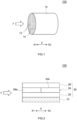
- FIG. 1 is a schematic view illustrating a structure of an exhaust gas purification catalyst 100 according to one embodiment, and particularly illustrates a structure of a base material 10.
- arrow F indicates a flow direction of an exhaust gas when the catalyst 100 is placed in the exhaust path.
- Arrow X indicates a cylinder axis direction of the base material 10.
- X1 denotes an upstream side in the exhaust gas flow direction F
- X2 denotes a downstream side in the exhaust gas flow direction F.
- the base material 10 constituting the exhaust gas purification catalyst 100 various materials and forms conventionally used in application of this type may be employed.
- these materials are preferably ceramic such as cordierite, aluminum titanate, and silicon carbide, because these ceramic materials have high heat resistance.
- a base material of an alloy e.g., stainless steel may be used.
- the base material 10 has a honeycomb structure including a plurality of regularly arranged cells 12 and a rib wall 14 defining the plurality of cells 12.
- the cells 12 are through holes serving as a passage of an exhaust gas.
- the rib wall 14 is a partition partitioning the cells 12.
- the rib wall 14 is configured such that an exhaust gas passing through the cells 12 can contact the rib wall 14.
- the cross-sectional shape of each of the cells 12 is a quadrangle in FIG. 1 , but may be other shapes (e.g., circle, triangle, hexagon, etc.).
- the outer shape of the base material 10 is a cylinder in FIG. 1 , but may be other shapes (e.g., oval cylinder, polygonal cylinder, etc.).
- the base material 10 is a honeycomb base material in FIG. 1 , but may have a foam shape, a pellet shape, etc.
- the volume of the base material 10 is typically about 0.1 to 10 L, and is, for example, 0.5 to 5 L.
- the length (overall length) of the base material 10 along the cylinder axis direction X is typically about 10 to 500 mm, and is, for example, 50 to 300 mm. It should be noted that the volume of the base material 10 herein refers to a bulk volume including a volume of internal gaps such as cells in addition to a pure volume of the base material.
- the base material 10 is a straight flow-type base material in which inlet openings and outlet openings of the cells 12 are not closed.
- the base material 10 may be a wall-flow type (i.e., wall-through type) base material in which inlet openings and outlet openings of a large number of cells 12 are alternately closed such that an exhaust gas flows through the rib wall from one cell (inlet cell) to an adjacent cell (outlet cell).
- FIG. 2 schematically illustrates a structure of a catalyst layer 20 included in the exhaust gas purification catalyst 100.
- FIG. 2 is a partial cross-sectional view of the exhaust gas purification catalyst 100.
- arrow F, arrow X, X1, and X2 has the same meanings as those in FIG. 1 .
- the catalyst layer 20 is formed on the base material 10.
- the catalyst layer 20 is formed on the internal surface of the base material 10.
- the catalyst layer 20 includes a lower layer 22 located on a side of the base material 10, an upper layer 26 located on a surface side of the catalyst layer 20, and an intermediate layer 24 located between the lower layer 22 and the upper layer 26.
- the intermediate layer 24 includes a front portion 24a located on an upstream side X1 in the exhaust gas flow direction F, and a rear portion 24b located on a downstream side X2 of the front portion 24a in the exhaust gas flow direction F.
- the catalyst layer 20 may include layers other than the lower layer 22, the intermediate layer 24, and the upper layer 26 within a range that does not significantly inhibit the effects of the present invention.
- the lower layer 22, the intermediate layer 24, and the upper layer 26 have the same thickness, but may have different thicknesses.
- the thickness of the lower layer 22 is not particularly limited, and is, for example, 10 ⁇ m to 30 ⁇ m, preferably 15 ⁇ m to 25 ⁇ m.
- the thickness of the intermediate layer 24 is not particularly limited, and is, for example, 40 ⁇ m to 60 ⁇ m, preferably 45 ⁇ m to 55 ⁇ m.
- the thickness of the upper layer 26 is not particularly limited, and is, for example, 20 ⁇ m to 40 ⁇ m, preferably 25 ⁇ m to 35 ⁇ m.
- the catalyst layer 20 (i.e., each of the lower layer 22, the intermediate layer 24, and the upper layer 26) contains a catalytic metal, and a substrate supporting the catalytic metal.
- the total content of the catalytic metal in the entire catalyst layer 20 is not particularly limited, and is, for example, 0.5 g/L or more, preferably 1.0 g/L or more, more preferably 2.0 g/L or more, as a content of the catalytic metal per 1 L of volume of the base material 10.
- the total content of the catalytic metal in the entire catalyst layer 20 is, for example, 8.0 g/L or less, preferably 7.0 g/L or less, more preferably 6.0 g/L or less, as a content of the catalytic metal per 1 L of volume of the base material 10.
- the coating amount of the entire catalyst layer 20 may be appropriately determined depending on the type of the base material 10, and is not particularly limited.
- the coating amount of the entire catalyst layer 20 is, for example, 150 g/L to 450 g/L, preferably 200 g/L to 400 g/L, more preferably 250 g/L to 350 g/L, as an amount per 1 L of volume of the base material 10.
- the coating length (average coating length of the base material 10 in the cylinder axis direction X) of the entire catalyst layer 20 is, for example, 60% or more of the overall length (average dimension in the cylinder axis direction X) of the base material 10, and may be 70% or more, 80% or more, 90% or more, or 100% of the overall length of the base material 10.
- the coating thickness (average thickness) of the catalyst layer 20 is, for example, 3 to 300 ⁇ m, and may be 5 to 200 ⁇ m or 10 to 100 ⁇ m.
- the catalytic metal included in the catalyst layer 20 is preferably fine particles with sufficiently small particle sizes.
- the average particle size of the catalytic metal is, for example, 1 nm to 15 nm, preferably 1 nm to 10 nm, more preferably 1 nm to 5 nm. It should be noted that the average particle size of the catalytic metal can be determined as an average value of particle sizes of 50 or more catalytic metal particles randomly selected in an image obtained as a transmission electron microscope (TEM) image of the catalytic metal.
- TEM transmission electron microscope
- a known material used as a substrate of a catalytic metal of an exhaust gas purification catalyst can be used.
- the substrate is typically an inorganic porous body.
- the substrate include: materials having no oxygen storage capacity (non-OSC materials) such as aluminium oxide (Al 2 O 3 , alumina), titanium oxide (TiO 2 , titania), zirconium oxide (ZrO 2 , zirconia), and silicon oxide (SiO 2 , silica); and materials having oxygen storage capacity (OSC materials) such as ceria (CeO 2 ) and composite oxides including ceria.
- the substrate may be either a non-OSC material or an OSC material and may be both.
- the non-OSC material is preferably Al 2 O 3 , more preferably Al 2 O 3 compounded with La 2 O 3 (La 2 O 3 -Al 2 O 3 composite oxide: LA composite oxide).
- the content of the non-OSC material in the catalyst layer 20 is not particularly limited, and is preferably 100 g/L or more and 370 g/L or less, more preferably 170 g/L or more and 300 g/L or less, as an amount per 1 L of volume of the base material 10.
- examples of the composite oxide containing ceria include a composite oxide containing ceria and zirconia (e.g., ceria-zirconia composite oxide, so-called CZ composite oxide or ZC composite oxide).
- the OSC material contains zirconium oxide, thermal degradation of cerium oxide can be suppressed and therefore, the OSC material is preferably ceria-zirconia composite oxide.
- the OSC material may contain an oxide of a rare-earth element, an alkali metal element, an alkali earth metal element, a transition metal element, Si, Al, and the like in order to enhance properties (especially heat resistance, oxygen absorbing/releasing capacity, etc.).
- the rare-earth element include Sc, Y, La, Pr, Nd, Pm, Sm, Eu, Gd, Tb, Dy, Ho, Er, Tm, Yb, and Lu.
- Preferred examples of an oxide of the rare-earth element include Pr 2 O 3 , Nd 2 O 3 , La 2 O 3 , and Y 2 O 3 .
- the content of cerium oxide is preferably 10 mass% or more, more preferably 25 mass% or more.
- the content of cerium oxide is preferably 90 mass% or less, more preferably 75 mass% or less.
- the content of the OSC material in the catalyst layer 20 is not particularly limited, and is preferably 45 g/L or more and 250 g/L or less, more preferably 80 g/L or more and 200 g/L or less, as an amount per 1 L of volume of the base material 10.
- the catalyst layer 20 may further contain the OSC material and/or the non-OSC material in the form of not supporting the catalytic metal.
- the catalyst layer 20 may include the non-OSC material supporting the catalytic metal and the OSC material supporting no catalytic metal.
- the catalyst layer 20 may include a binder, an additive, and so forth.
- the binder include alumina sol and silica sol.
- the lower layer 22, the intermediate layer 24, and the upper layer 26 included in the catalyst layer 20 will be described in detail below.
- the lower layer 22 contains a catalytic metal.
- the catalytic metal various metal species that can function as oxidation catalysts and/or reduction catalysts in purification of harmful components of an exhaust gas can be used.
- the catalytic metal include a platinum group, that is, rhodium (Rh), palladium (Pd), platinum (Pt), ruthenium (Ru), osmium (Os), and iridium (Ir).
- platinum group rhodium (Rh), palladium (Pd), platinum (Pt), ruthenium (Ru), osmium (Os), and iridium (Ir).
- metal species such as iron (Fe), cobalt (Co), nickel (Ni), copper (Cu), silver (Ag), and gold (Au) may be used.
- the catalytic metal included in the lower layer 22 preferably has high oxidation activity (HC and CO purification capacity).
- the catalytic metal included in the lower layer 22 is preferably at least one of Pd and Pt, more preferably Pd.
- Pd has a merit that Pd does not easily degrade its activity even in an oxidation state, as compared to other catalytic metals.
- the content of the catalytic metal in the lower layer 22 is not particularly limited. When the content of the catalytic metal is excessively small, catalyst activity obtained by the catalytic metal might be insufficient. On the other hand, when the content of the catalytic metal is excessively large, the catalytic metal tends to cause grain growth and, at the same time, it is disadvantageous in terms of cost. In view of this, the content of the catalytic metal in the lower layer 22 is preferably 0.1 g/L to 5 g/L, more preferably 0.5 g/L to 3 g/L, as the amount of the catalytic metal (especially Pd) per 1 L of volume of the base material 10.
- the lower layer 22 preferably includes an OSC material.
- the OSC material may be a substrate or a non-substrate.
- the lower layer 22 more preferably includes an OSC material and a non-OSC material.
- the content of the OSC material in the lower layer 22 is preferably 20 g/L to 100 g/L, more preferably 30 g/L to 80 g/L, as an amount per 1 L of volume of the base material 10.
- the content of the non-OSC material in the lower layer 22 is preferably 30 g/L to 130 g/L, more preferably 50 g/L to 100 g/L, as an amount per 1 L of volume of the base material 10.
- the lower layer 22 may contain a subsidiary material including an alkali metal element, an alkali earth metal element, a rare earth metal element, a transition metal element, and the like.
- the subsidiary material may be an oxide, a hydroxide, a carbonate, a nitrate, a sulfate, a phosphate, an acetate, a formate, an oxalate, a halide or the like of these elements.
- the alkaline earth element e.g., calcium (Ca), barium (Ba), etc.
- the alkaline earth element can suppress poisoning of the catalytic metal (especially oxidation catalyst).
- the alkaline earth element enhances dispersibility of the catalytic metal to thereby reduce sintering caused with grain growth of the catalytic metal.
- the amount of oxygen absorption into the OSC material can be further increased under a lean atmosphere (oxygen-rich atmosphere), where the fuel is leaner than the stoichiometric air-fuel ratio.
- the lower layer 22 does not need to substantially include the NOx storage material.
- a layer substantially does not include a component herein means that the content of this component in the total mass of the layer is 1 mass% or less (preferably 0.5 mass% or less, more preferably 0.1 mass% or less, even more preferably 0 mass%).
- the lower layer 22 substantially does not include a NOx storage material, a subsidiary material including an alkali metal element, and a subsidiary material including an alkali earth metal element.
- the intermediate layer 24 serves as a catalyst layer and a NOx storage layer.
- Each of the front portion 24a and the rear portion 24b of the intermediate layer 24 contains Pt as a catalytic metal.
- Pt has highest NO oxidation performance in the catalytic metals, and thus, by allowing the intermediate layer 24 to contain Pt, NO can be converted to NO 2 , which is a form of being absorbed by the NOx storage material, near the NOx storage material.
- NO can be converted to NO 2 , which is a form of being absorbed by the NOx storage material, near the NOx storage material.
- Pt has high reactivity to paraffin-based HC
- the content of Pt in the intermediate layer 24 is not particularly limited. When the content of Pt is excessively small, catalyst activity obtained by Pt might be insufficient.
- the content of Pt per 1 L of volume of the base material 10 is preferably 0.1 g/L to 5 g/L, more preferably 0.5 g/L to 3 g/L.
- a concentration (P A ) of Pt in the front portion 24a of the intermediate layer 24 is preferably approximately equal to a concentration (P B ) of Pt in the rear portion 24b of the intermediate layer 24.
- Each of the front portion 24a and the rear portion 24b of the intermediate layer 24 contains a NOx storage material including at least one NOx storage element selected from the group consisting of an alkali metal and an alkali earth metal.
- the NOx storage material is not particularly limited to a specific type as long as the NOx storage material includes the elements described above, and the NOx storage material is typically a component including the at least one NOx storage element and being in the form of a carbonate or an oxide, or a combination thereof.
- the alkali metal include Li, K, and Cs, and among these elements, K is preferable.
- the alkali earth metal include Mg, Sr, Ba, and among these elements, Ba is preferable.
- the NOx storage material is particularly preferably a compound selected from the group consisting of an oxide including Ba and a carbonate including Ba.
- a concentration (C B ) of the NOx storage element included in the rear portion 24b per 1 L of the base material (hereinafter referred to as a “NOx storage element concentration (C B ) of the rear portion 24b") is higher than a concentration (C A ) of the NOx storage element included in the front portion 24a per 1 L of the base material (hereinafter referred to as a “NOx storage element concentration (C A ) of the front portion 24a").
- a ratio (C A /C B ) of the NOx storage element concentration (C A ) of the front portion 24a to the NOx storage element concentration (C B ) of the rear portion 24b satisfies 0 ⁇ C A /C B ⁇ 1.
- the catalyst layer 20 is gradually warmed by the exhaust gas from a front portion thereof, and thus, a temperature distribution occurs in the catalyst layer 20.
- the front portion 24a of the intermediate layer 24 of the catalyst layer 20 releases stored NO 2 with a temperature rise, but in the rear portion of the catalyst layer 20, the catalyst is not sufficiently heated to the activation temperature, and cannot purify NOx completely.
- the rear portion 24b of the intermediate layer 24 of the catalyst layer 20 includes a larger amount of the NOx storage material than the front portion 24a. Accordingly, even in a case where the rear portion of the catalyst layer 20 is insufficiently warmed at start of the internal combustion engine, the NOx storage material of the rear portion 24b in an amount larger than in the front portion 24a can store NO 2 released from the front portion 24a. In this manner, it is possible to suppress release of NOx as an emission at start of the internal combustion engine.
- the NOx storage material in the rear portion 24b in an amount larger than in the front portion 24a can absorb NO 2 released from the front portion 24a.
- the ratio (C A /C B ) preferably satisfies 0.1 ⁇ C A /C B ⁇ 0.85, more preferably satisfies 0.2 ⁇ C A /C B ⁇ 0.8, even more preferably satisfies 0.4 ⁇ C A /C B ⁇ 0.7.
- the NOx storage element concentration (C A ) of the front portion 24a is preferably more than 0 g/L and 20 g/L or less, and the concentration (C B ) of the NOx storage material in the rear portion 24b is preferably 20 g/L or more.
- the NOx storage element concentration (C A ) of the front portion 24a is preferably 3 g/L or more, more preferably 5 g/L or more.
- the NOx storage element concentration (C B ) of the rear portion 24b is more preferably 30 g/L or more, even more preferably 37.5 g/L or more. It should be noted that for reasons such as manufacturing limitations, the NOx storage element concentration (C B ) of the rear portion 24b can be 40 g/L or less.
- the intermediate layer 24 preferably includes an OSC material.
- the OSC material may be a substrate or a non-substrate.
- the intermediate layer 24 more preferably includes an OSC material and a non-OSC material.
- the content of the OSC material in the intermediate layer 24 is preferably 20 g/L to 100 g/L, more preferably 40 g/L to 80 g/L, as an amount per 1 L of volume of the base material 10.
- the content of the non-OSC material in the intermediate layer 24 is preferably 40 g/L to 120 g/L, more preferably 60 g/L to 100 g/L, as an amount per 1 L of volume of the base material 10.
- the front portion 24a and the rear portion 24b are in contact with each other.
- the front portion 24a and the rear portion 24b may be separated from each other.
- an end portion of the front portion 24a and an end portion of the rear portion 24b may partially overlap each other.
- an end portion of the front portion 24a and an end portion of the rear portion 24b can partially overlap each other.
- an analysis of the NOx storage element concentration (C A ) of the front portion 24a and the NOx storage element concentration (C B ) of the rear portion 24b may be performed at a position corresponding to 30% of the length of the base material 10 from an end portion of the base material 10.
- the coating length of the front portion 24a is preferably 30% to 70%, more preferably 40% to 60%, even more preferably 45% to 55%, of the overall length (i.e., average dimension in the cylinder axis direction) of the base material 10.
- the coating length of the rear portion 24b is preferably 30% to 70%, more preferably 40% to 60%, even more preferably 45% to 55%, of the overall length of the base material 10.
- the upper layer 26 contains Rh as a catalytic metal. Rh has higher H 2 generation capacity and higher three-way performance than other catalytic metals. In particular, Rh has high NOx purification capacity. Thus, since the upper layer 26 located closer to the surface portion than the intermediate layer 24 contains Rh as a catalytic metal, when NOx stored in the intermediate layer 24 is released, NOx can be efficiently removed.
- the content of Rh in the upper layer 26 is not particularly limited. When the content of Rh is excessively small, catalyst activity obtained by Rh might be insufficient. On the other hand, when the content of Rh is excessively large, Rh tends to cause grain growth and, at the same time, it is disadvantageous in terms of cost.
- the content of Rh per 1 L of volume of the base material 10 is preferably 0.01 g/L to 1.0 g/L, more preferably 0.05 g/L to 0.5 g/L.
- the upper layer 26 preferably includes an OSC material.
- the OSC material may be a substrate or a non-substrate.
- the upper layer 26 more preferably includes an OSC material and a non-OSC material.
- the content of the OSC material in the upper layer 26 is preferably 5 g/L to 50 g/L, more preferably 10 g/L to 40 g/L, as an amount per 1 L of volume of the base material 10.
- the content of the non-OSC material in the upper layer 26 is preferably 40 g/L to 120 g/L, more preferably 60 g/L to 100 g/L, as an amount per 1 L of volume of the base material 10.
- the upper layer 26 may contain a subsidiary material including a rare earth metal element, a transition metal element, or the like.
- the upper layer 26 does not need to substantially include the NOx storage material.
- the upper layer 26 substantially does not include a NOx storage material, a subsidiary material including an alkali metal element, and a subsidiary material including an alkali earth metal element.
- the exhaust gas purification catalyst 100 including the catalyst layer 20 having a unique multilayer structure can purify NOx with high efficiency while suppressing release of NOx as an emission at start of an internal combustion engine, and thus, has high NOx purification performance.
- the exhaust gas purification catalyst 100 can be produced by, for example, the following method.
- a base material 10 and a catalyst layer slurry for forming a catalyst layer 20 are prepared.
- the catalyst layer slurry can be prepared by mixing, for example, a catalytic metal source (e.g., solution containing a catalytic metal as ions) and other components (e.g., NOx storage material, non-OSC material, OSC material, binder, various additives, etc.) in a dispersion medium.
- a catalytic metal source e.g., solution containing a catalytic metal as ions
- other components e.g., NOx storage material, non-OSC material, OSC material, binder, various additives, etc.
- the dispersion medium include water and a mixture of water and a water-soluble organic solvent.
- Properties (e.g., viscosity, solid content, etc.) of slurry can be appropriately determined depending on the size of the base material 10 to be used, the form of the cells 12 (rib wall 14), properties required for the catalyst layer 20, and so forth. It is advantageous for adjusting viscosity of slurry to use cellulose-based polymer such as carboxymethyl cellulose (CMC), methyl cellulose (MC), hydroxypropyl methyl cellulose (HPMC), or hydroxyethylmethyl cellulose (HEMC).
- CMC carboxymethyl cellulose
- MC methyl cellulose
- HPMC hydroxypropyl methyl cellulose
- HEMC hydroxyethylmethyl cellulose
- lower layer slurry containing a catalytic metal source intermediate layer slurry containing a Pt source and a NOx storage material
- upper layer slurry containing a Rh source are prepared.
- intermediate layer front portion slurry in which the concentrations of the alkali metal element and the alkali earth metal element included in the NOx storage material are low relative to the total solid contents
- intermediate layer rear portion slurry in which the concentrations of the alkali metal element and the alkali earth metal element included in the NOx storage material are high relative to the total solid contents are prepared.
- the lower layer slurry is applied onto the base material by a known application method (e.g., impregnation, wash coating, etc.), dried, and then fired, thereby forming a lower layer.
- a known application method e.g., impregnation, wash coating, etc.
- the intermediate layer front portion slurry is applied onto an area of the base material from a front-side end to a predetermined position by a known method, and dried.
- the intermediate layer rear portion slurry is applied onto an area of the base material from a rear-side end to a predetermined position by a known method, and dried. Then, the resultant is fired, thereby forming an intermediate layer.
- upper layer slurry is applied onto the intermediate layer by a known coating method, dried, and then fired, thereby forming an upper layer.
- Drying conditions vary depending on the shape and size of the base material or the substrate, and are typically about 70 to 150°C (e.g., 90 to 130°C) for about 1 to 10 hours. Firing conditions are typically about 300 to 800°C (e.g., 400 to 500°C) for about 1 to 4 hours. In the foregoing manner, the exhaust gas purification catalyst 100 can be obtained.
- the exhaust gas purification catalyst 100 is preferably applicable to purification of an exhaust gas emitted from internal combustion engines of marine products such as ships, tankers, water bikes, personal watercrafts and outboard motors, gardening products such as grass mowers, chain saws, and trimmers, leisure products such as golf carts and four-wheeled buggies, power generation facilities such as cogeneration systems, refuse incinerators, and the like as well as vehicles such as automobiles and trucks, autobicycles, and motorcycles.
- the catalyst 100 is suitably applicable to vehicles such as automobiles, and particularly suitably applicable to vehicles including gasoline engines.
- Cylindrical cordierite honeycomb base materials each having a diameter of 118.4 mm, an overall length of 114.3 mm, and a base material capacity of 1.26 L as illustrated in FIG. 1 were prepared as base materials of examples and comparative examples.
- One end of each base material is defined as a front-side end (i.e., exhaust gas inflow end), and the other end is defined as a rear-side end (i.e., exhaust gas outflow end).
- a palladium nitrate aqueous solution, ZC composite oxide powder, Al 2 O 3 powder, and ion-exchanged water were mixed, thereby preparing lower layer Pd-containing slurry.
- This lower layer Pd-containing slurry was applied by wash coating onto each of the base materials described above over 100% of the length (dimension in the cylinder axis direction) of the base material. Thie slurry was dried at 90°C for one hour, and then fired at 500°C for one hour, thereby forming a lower layer.
- the Pd amount per a unit volume of the base material was 74 g/cft (about 2.61 g/L).
- a platinum nitrate aqueous solution, ZC composite oxide powder, Al 2 O 3 powder, barium carbonate, and ion-exchanged water were mixed, thereby preparing intermediate layer Pt-containing slurry.
- Multiple types of the intermediate layer Pt-containing slurry with different Ba amounts were prepared.
- Intermediate layer Pt-containing slurry containing no barium carbonate was also prepared.
- first intermediate layer Pt-containing slurry was applied by wash coating onto an area of each of the base material from the front-side end to 50% of the length of the base material, dried at 90°C for one hour, and then fired at 500°C for one hour, thereby forming a front portion.
- Second intermediate layer Pt-containing slurry was applied by wash coating onto an area of each base material from the rear-side end to 50% of the length of the base material, dried at 90°C for one hour, and then fired at 500°C for one hour, thereby forming a rear portion. In this manner, an intermediate layer including the front portion and the rear portion was formed.
- each of the first intermediate layer Pt-containing slurry and the second intermediate layer Pt-containing slurry were selected such that the Ba concentration (C A ) of the front portion and the Ba concentration (C B ) of the rear portion per 1 L of the base material had values shown in Table 1.
- the P amounts per a unit volume of the base material were the same in the front portion and the rear portion, and were 30 g/cft (about 1.06 g/L).
- the lower layer Pd-containing slurry described above was applied by wash coating onto the base material described above over 100% of the length of the base material. This slurry was dried at 90°C for one hour, and then fired at 500°C for one hour, thereby forming a lower layer.
- the Pd amount per a unit volume of the base material was 74 g/cft (about 2.61 g/L).
- a platinum nitrate aqueous solution, a rhodium nitrate aqueous solution, ZC composite oxide powder, Al 2 O 3 powder, barium carbonate, and ion-exchanged water were mixed, thereby preparing upper layer Pt, Rh-containing slurry.
- Two types of the upper layer Pt, Rh-containing slurry with different Ba amounts were prepared. Then, first upper layer Pt, Rh-containing slurry was applied by wash coating onto an area of the base material from the front-side end to 50% of the length of the base material, dried at 90°C for one hour, and then fired at 500°C for one hour, thereby forming a front portion.
- Second upper layer Pt Rh-containing slurry was applied by wash coating onto an area of the base material from the rear-side end to 50% of the length of the base material, dried at 90°C for one hour, and then fired at 500°C for one hour, thereby forming a rear portion. In this manner, an upper layer including the front portion and the rear portion was formed. At this time, the upper layer was formed such that the Ba concentration (C A ) of the front portion and the Ba concentration (C B ) of the rear portion per 1 L of the base material had values shown in Table 1.
- the Pt amount per a unit volume of the base material was 30 g/cft (about 1.06 g/L) in both the front portion and the rear portion, and the Pd amount per a unit volume of the base material was 37 g/cft (about 1.31 g/L) in both the front portion and the rear portion. In this manner, the exhaust gas purification catalyst of Comparative Example 6 was obtained.
- the exhaust gas purification catalysts of the examples and the comparative examples were cooled to 100°C or below, and then placed in an exhaust pipe of an engine bench.
- An exhaust gas with a ⁇ value of 1.08 subjected to temperature adjustment to 300°C by a heat exchanger was caused to flow into the exhaust gas purification catalysts.
- an NOx concentration at a position before a catalyst inflow and a NOx concentration at a position after a catalyst outflow were measured, and based on the measured values, a NOx storage amount (mg/L) per 1 L of the base material was calculated. Table 1 shows the results.
- the exhaust gas purification catalysts of the examples and the comparative examples were cooled to 100°C or below, and then placed in an exhaust pipe of an engine bench. An exhaust gas with a ⁇ value of 1.08 subjected to temperature adjustment to 300°C by a heat exchanger was caused to flow into the exhaust gas purification catalysts. At this time, a NOx integrated quantity at a position before a catalyst inflow for 180 seconds and a NOx integrated quantity at a position after a catalyst outflow for 180 were measured, and based on the measured values, a NOx purification rate (%) was calculated. Table 1 shows the results.
- the exhaust gas purification catalyst disclosed here is an exhaust gas purification catalyst including a NOx storage layer and having high NOx purification performance.
Landscapes
- Chemical & Material Sciences (AREA)
- Engineering & Computer Science (AREA)
- Chemical Kinetics & Catalysis (AREA)
- Materials Engineering (AREA)
- Organic Chemistry (AREA)
- Combustion & Propulsion (AREA)
- Mechanical Engineering (AREA)
- General Engineering & Computer Science (AREA)
- Health & Medical Sciences (AREA)
- Toxicology (AREA)
- Biomedical Technology (AREA)
- Environmental & Geological Engineering (AREA)
- Analytical Chemistry (AREA)
- General Chemical & Material Sciences (AREA)
- Oil, Petroleum & Natural Gas (AREA)
- Catalysts (AREA)
- Exhaust Gas Treatment By Means Of Catalyst (AREA)
- Exhaust Gas After Treatment (AREA)
Abstract
Description
- The present invention relates to an exhaust gas purification catalyst. More particularly, the present invention relates to an exhaust gas purification catalyst which includes a base material and a catalyst layer disposed on the base material and in which the catalyst layer includes a NOx storage layer. This application claims the benefit of priority to
Japanese Patent Application No. 2022-036273 filed on March 9, 2022 - Exhaust gas purification catalysts have been used to remove harmful components such as hydrocarbon (HC), carbon monoxide (CO), and nitrogen oxide (NOx) from exhaust gas emitted from internal combustion engines such as automobile engines. These exhaust gas purification catalysts widely employ a three-way catalyst including a catalytic metal. Due to high efficiency in removing harmful components, Rh (rhodium) as well as Pt (platinum) and/or Pd (palladium) are often used in combination as a catalytic metal. In a typical configuration of an exhaust gas purification catalyst, a catalyst layer including a three-way catalyst is disposed on a base material (see, for example, Patent Documents 1 to 5).
- In regard to NOx removal, an alkali metal component and an alkali earth metal component can temporarily store NOx, and thus, are used as NOx storage material in Patent Documents 1 to 5. In particular, Patent Document 1 describes that a catalyst layer has a threelayer structure in which an intermediate layer among the three layers is configured as a NOx storage layer containing an alkali metal component or an alkali earth metal component as a NOx storage material and moreover, an upper layer is configured as a NOx reduction layer containing Rh to thereby achieve high NOx purification performance.
-
- Patent Document 1:
Japanese Patent Application Publication No. 2018-143935 - Patent Document 2: Patent Document 2: International Patent Publication No.
2020/153309 - Patent Document 3:
Japanese Patent Application Publication No. 2015-502855 - Patent Document 4:
Japanese Patent Application Publication No. 2016-93760 - Patent Document 5:
Japanese Patent Application Publication No. 2003-24793 - An intensive study of inventors of the present invention, however, found that conventional techniques typified by Patent Document 1 still have room for improvement of NOx purification performance.
- It is therefore an object of the present invention to provide an exhaust gas purification catalyst including a NOx storage layer and exhibiting high NOx purification performance. Solution to Problem
- Through an intensive study, the inventors of the present invention found the followings. Storage of NOx by a NOx storage material including an alkali metal component or an alkali earth metal component occurs through a process in which NO is oxidized to NO2 by a catalytic metal and this NO2 reacts with the alkali metal component or the alkali earth metal component. Stored NOx is desorbed from these components by a temperature rise. On the other hand, to allow a catalyst to show high activity, the catalyst needs to be heated to a predetermined temperature (i.e., activation temperature) or more. Thus, in a catalyst warm-up process at start of an internal combustion engine such as an engine, a NOx storage material stores NO2 in an exhaust gas and, after catalyst warm-up, releases NO2, and the catalyst activated by heating purifies released NO2, so that the NOx amount in the exhaust gas is thereby reduced.
- At start of the internal combustion engine, the catalyst layer is gradually warmed by an exhaust gas from a front portion thereof, and accordingly, temperature distribution occurs in the catalyst layer. Consequently, the front portion of the catalyst layer releases stored NO2 with a temperature rise, but in a rear portion of the catalyst layer, the catalyst is not heated to the activation temperature and cannot purify NOx completely. Consequently, in the conventional technique described above, NOx can be released as an emission.
- The exhaust gas purification catalyst disclosed here is completed based on the foregoing findings. Specifically, the exhaust gas purification catalyst disclosed here is placed in an exhaust path of an internal combustion engine and used for purifying an exhaust gas from the internal combustion engine. Therefore, the exhaust gas purification catalyst is configured to be placed in an exhaust path of an internal combustion engine and configured to purify an exhaust gas from the internal combustion engine.
- An exhaust gas purification catalyst disclosed here includes a base material and a catalyst layer disposed on the base material. The catalyst layer includes a lower layer located on a base material side, an upper layer located on a surface side, and an intermediate layer located between the lower layer and the upper layer. The lower layer contains a catalytic metal. The upper layer contains Rh. The intermediate layer includes a front portion and a rear portion, the front portion being located on an upstream side in an exhaust gas flow direction when the catalyst is placed in the exhaust path, the rear portion being located downstream of the front portion in the exhaust gas flow direction. Each of the front portion and the rear portion of the intermediate layer contains Pt and a NOx storage material. The NOx storage material includes at least one NOx storage element selected from the group consisting of an alkali metal element and an alkali earth metal element. A ratio (CA/CB) of a concentration (CA) of the NOx storage element included in the front portion per 1 L of the base material to a concentration (CB) of the NOx storage element included in the rear portion per 1 L of the base material satisfies 0 < CA/CB < 1.
- With this configuration, the catalyst layer with the multilayer structure includes the NOx storage layer having the front portion located on the upstream side in the exhaust gas flow direction and the downstream rear portion, and the concentration of the NOx storage material in the rear portion is different form the concentration of the NOx storage material in the front portion, and is made higher than the concentration of the NOx storage material in the front portion. Thus, with this configuration, even in a case where the rear portion of the catalyst layer is insufficiently warmed at start of an internal combustion engine, the NOx storage material in the rear portion larger in amount than that in the front portion in the NOx storage layer can store NO2 released from the front portion. In addition, since the NOx storage layer contains Pt, NOx storage efficiency is enhanced.
- Furthermore, in the exhaust gas purification catalyst disclosed here, the layer containing Rh is located above the NOx storage layer. With this configuration, when NO2 is released from the NOx storage material in the rear portion, NO2 can be efficiently purified. As a result, the exhaust gas purification catalyst disclosed here can purify NOx with high efficiency while reducing release of NOx as an emission at start of an internal combustion engine, thereby exhibiting high NOx purification performance.
- In a preferred aspect of the exhaust gas purification catalyst disclosed here, the ratio (CA/CB) satisfies 0.2 < CA/CB < 0.8. With this configuration, NOx purification performance is further enhanced.
- In a more preferred aspect of the exhaust gas purification catalyst disclosed here, the ratio (CA/CB) satisfies 0.4 < CA/CB < 0.7. With this configuration, NOx purification performance is particularly enhanced.
- In a preferred aspect of the exhaust gas purification catalyst disclosed here, the concentration (CA) of the NOx storage element included in the front portion per 1 L of the base material is more than 0 g/L and 20 g/L or less, and the concentration (CB) of the NOx storage element included in the rear portion is 20 g/L or more. With this configuration, NOx purification performance is further enhanced.
- In a preferred aspect of the exhaust gas purification catalyst disclosed here, the catalytic metal included in the lower layer is Pd. With this configuration, particularly high purification performance for harmful components of an exhaust gas including HC and CO is obtained.
-
- [
FIG. 1 ] A perspective view schematically illustrating an exhaust gas purification catalyst according to one embodiment. - [
FIG. 2 ] A partial cross-sectional view of the exhaust gas purification catalyst inFIG. 1 taken along a cylinder axis direction. - A preferred embodiment of the present invention will be described hereinafter with reference to the drawings. Matters not specifically mentioned in the description but required for carrying out the present invention can be understood as matters of design of a person skilled in the art based on related art in the field. The present invention can be carried out on the basis of the contents disclosed in the description and common general knowledge in the field. In the drawings, members and parts having the same functions are denoted by the same reference characters, and description will not be repeated or will be simplified. Dimensional relationships (e.g., length, width, and thickness) in the drawings do not necessarily reflect actual dimensional relationships. The expression "A to B" (where A and B are any numerical values) representing a range herein includes "preferably greater than A" and "preferably less than B" as well as "A or more and B or less."
- An exhaust gas purification catalyst disclosed here is to be placed in an exhaust path of an internal combustion engine and used for purifying an exhaust gas from the internal combustion engine. The exhaust gas purification catalyst includes at least a base material and a catalyst layer on the base material, and the catalyst layer has a unique multilayer structure. The exhaust gas purification catalyst disclosed here can be placed in exhaust systems (exhaust pipes) of various internal combustion engines, especially automobile engines, by appropriately selecting the type and shape of the base material, design of the catalyst layer, and so forth. An exhaust gas purification catalyst disclosed here will be hereinafter described based on the premise that an internal combustion engine is an automobile gasoline engine, but it is not intended to limit the exhaust gas purification catalyst disclosed here to such application.
-
FIG. 1 is a schematic view illustrating a structure of an exhaustgas purification catalyst 100 according to one embodiment, and particularly illustrates a structure of abase material 10. InFIG. 1 , arrow F indicates a flow direction of an exhaust gas when thecatalyst 100 is placed in the exhaust path. Arrow X indicates a cylinder axis direction of thebase material 10. X1 denotes an upstream side in the exhaust gas flow direction F, and X2 denotes a downstream side in the exhaust gas flow direction F. - As the
base material 10 constituting the exhaustgas purification catalyst 100, various materials and forms conventionally used in application of this type may be employed. For example, these materials are preferably ceramic such as cordierite, aluminum titanate, and silicon carbide, because these ceramic materials have high heat resistance. Alternatively, a base material of an alloy (e.g., stainless steel) may be used. - In regard to the form, in
FIG. 1 , for example, thebase material 10 has a honeycomb structure including a plurality of regularly arrangedcells 12 and arib wall 14 defining the plurality ofcells 12. Thecells 12 are through holes serving as a passage of an exhaust gas. Therib wall 14 is a partition partitioning thecells 12. Therib wall 14 is configured such that an exhaust gas passing through thecells 12 can contact therib wall 14. The cross-sectional shape of each of thecells 12 is a quadrangle inFIG. 1 , but may be other shapes (e.g., circle, triangle, hexagon, etc.). - The outer shape of the
base material 10 is a cylinder inFIG. 1 , but may be other shapes (e.g., oval cylinder, polygonal cylinder, etc.). Thebase material 10 is a honeycomb base material inFIG. 1 , but may have a foam shape, a pellet shape, etc. The volume of thebase material 10 is typically about 0.1 to 10 L, and is, for example, 0.5 to 5 L. The length (overall length) of thebase material 10 along the cylinder axis direction X is typically about 10 to 500 mm, and is, for example, 50 to 300 mm. It should be noted that the volume of thebase material 10 herein refers to a bulk volume including a volume of internal gaps such as cells in addition to a pure volume of the base material. - In
FIG. 1 , thebase material 10 is a straight flow-type base material in which inlet openings and outlet openings of thecells 12 are not closed. Alternatively, thebase material 10 may be a wall-flow type (i.e., wall-through type) base material in which inlet openings and outlet openings of a large number ofcells 12 are alternately closed such that an exhaust gas flows through the rib wall from one cell (inlet cell) to an adjacent cell (outlet cell). -
FIG. 2 schematically illustrates a structure of acatalyst layer 20 included in the exhaustgas purification catalyst 100.FIG. 2 is a partial cross-sectional view of the exhaustgas purification catalyst 100. InFIG. 2 , arrow F, arrow X, X1, and X2 has the same meanings as those inFIG. 1 . - As illustrated in
FIG. 2 , thecatalyst layer 20 is formed on thebase material 10. Typically, thecatalyst layer 20 is formed on the internal surface of thebase material 10. Thecatalyst layer 20 includes alower layer 22 located on a side of thebase material 10, anupper layer 26 located on a surface side of thecatalyst layer 20, and anintermediate layer 24 located between thelower layer 22 and theupper layer 26. Theintermediate layer 24 includes afront portion 24a located on an upstream side X1 in the exhaust gas flow direction F, and arear portion 24b located on a downstream side X2 of thefront portion 24a in the exhaust gas flow direction F. - It should be noted that the
catalyst layer 20 may include layers other than thelower layer 22, theintermediate layer 24, and theupper layer 26 within a range that does not significantly inhibit the effects of the present invention. In the illustrated example, thelower layer 22, theintermediate layer 24, and theupper layer 26 have the same thickness, but may have different thicknesses. The thickness of thelower layer 22 is not particularly limited, and is, for example, 10 µm to 30 µm, preferably 15 µm to 25 µm. The thickness of theintermediate layer 24 is not particularly limited, and is, for example, 40 µm to 60 µm, preferably 45 µm to 55 µm. The thickness of theupper layer 26 is not particularly limited, and is, for example, 20 µm to 40 µm, preferably 25 µm to 35 µm. - The catalyst layer 20 (i.e., each of the
lower layer 22, theintermediate layer 24, and the upper layer 26) contains a catalytic metal, and a substrate supporting the catalytic metal. - Tye type of the catalytic metal included in each of the
lower layer 22, theintermediate layer 24, and theupper layer 26 will be described in detail later. The total content of the catalytic metal in theentire catalyst layer 20 is not particularly limited, and is, for example, 0.5 g/L or more, preferably 1.0 g/L or more, more preferably 2.0 g/L or more, as a content of the catalytic metal per 1 L of volume of thebase material 10. On the other hand, the total content of the catalytic metal in theentire catalyst layer 20 is, for example, 8.0 g/L or less, preferably 7.0 g/L or less, more preferably 6.0 g/L or less, as a content of the catalytic metal per 1 L of volume of thebase material 10. - The coating amount of the
entire catalyst layer 20 may be appropriately determined depending on the type of thebase material 10, and is not particularly limited. The coating amount of theentire catalyst layer 20 is, for example, 150 g/L to 450 g/L, preferably 200 g/L to 400 g/L, more preferably 250 g/L to 350 g/L, as an amount per 1 L of volume of thebase material 10. - The coating length (average coating length of the
base material 10 in the cylinder axis direction X) of theentire catalyst layer 20 is, for example, 60% or more of the overall length (average dimension in the cylinder axis direction X) of thebase material 10, and may be 70% or more, 80% or more, 90% or more, or 100% of the overall length of thebase material 10. - The coating thickness (average thickness) of the
catalyst layer 20 is, for example, 3 to 300 µm, and may be 5 to 200 µm or 10 to 100 µm. - From the viewpoint of increasing the contact area with an exhaust gas, the catalytic metal included in the
catalyst layer 20 is preferably fine particles with sufficiently small particle sizes. The average particle size of the catalytic metal is, for example, 1 nm to 15 nm, preferably 1 nm to 10 nm, more preferably 1 nm to 5 nm. It should be noted that the average particle size of the catalytic metal can be determined as an average value of particle sizes of 50 or more catalytic metal particles randomly selected in an image obtained as a transmission electron microscope (TEM) image of the catalytic metal. - As a substrate supporting the catalytic metal, a known material used as a substrate of a catalytic metal of an exhaust gas purification catalyst can be used. The substrate is typically an inorganic porous body. Examples of the substrate include: materials having no oxygen storage capacity (non-OSC materials) such as aluminium oxide (Al2O3, alumina), titanium oxide (TiO2, titania), zirconium oxide (ZrO2, zirconia), and silicon oxide (SiO2, silica); and materials having oxygen storage capacity (OSC materials) such as ceria (CeO2) and composite oxides including ceria. The substrate may be either a non-OSC material or an OSC material and may be both.
- To increase heat resistance and other properties, a small amount (e.g., 1 mass% or more and 10 mass% or less) of an oxide of a rare-earth element such as Pr2O3, Nd2O3, La2O3, or Y2O3 may be added to an oxide used as a non-OSC material. From the viewpoint of especially high heat resistance and durability, the non-OSC material is preferably Al2O3, more preferably Al2O3 compounded with La2O3 (La2O3-Al2O3 composite oxide: LA composite oxide).
- The content of the non-OSC material in the
catalyst layer 20 is not particularly limited, and is preferably 100 g/L or more and 370 g/L or less, more preferably 170 g/L or more and 300 g/L or less, as an amount per 1 L of volume of thebase material 10. - Concerning the OSC material, examples of the composite oxide containing ceria include a composite oxide containing ceria and zirconia (e.g., ceria-zirconia composite oxide, so-called CZ composite oxide or ZC composite oxide). When the OSC material contains zirconium oxide, thermal degradation of cerium oxide can be suppressed and therefore, the OSC material is preferably ceria-zirconia composite oxide.
- The OSC material may contain an oxide of a rare-earth element, an alkali metal element, an alkali earth metal element, a transition metal element, Si, Al, and the like in order to enhance properties (especially heat resistance, oxygen absorbing/releasing capacity, etc.). Examples of the rare-earth element include Sc, Y, La, Pr, Nd, Pm, Sm, Eu, Gd, Tb, Dy, Ho, Er, Tm, Yb, and Lu. Preferred examples of an oxide of the rare-earth element include Pr2O3, Nd2O3, La2O3, and Y2O3.
- In a case where the OSC material is a composite oxide including cerium oxide, from the viewpoint of sufficiently exhibiting oxygen storage capacity thereof, the content of cerium oxide is preferably 10 mass% or more, more preferably 25 mass% or more. On the other hand, when the content of cerium oxide is excessively high, basicity of the OSC material might be excessively high. For this reason, the content of cerium oxide is preferably 90 mass% or less, more preferably 75 mass% or less.
- The content of the OSC material in the
catalyst layer 20 is not particularly limited, and is preferably 45 g/L or more and 250 g/L or less, more preferably 80 g/L or more and 200 g/L or less, as an amount per 1 L of volume of thebase material 10. - The
catalyst layer 20 may further contain the OSC material and/or the non-OSC material in the form of not supporting the catalytic metal. For example, thecatalyst layer 20 may include the non-OSC material supporting the catalytic metal and the OSC material supporting no catalytic metal. - The
catalyst layer 20 may include a binder, an additive, and so forth. Examples of the binder include alumina sol and silica sol. - The
lower layer 22, theintermediate layer 24, and theupper layer 26 included in thecatalyst layer 20 will be described in detail below. - The
lower layer 22 contains a catalytic metal. As the catalytic metal, various metal species that can function as oxidation catalysts and/or reduction catalysts in purification of harmful components of an exhaust gas can be used. Typical examples of the catalytic metal include a platinum group, that is, rhodium (Rh), palladium (Pd), platinum (Pt), ruthenium (Ru), osmium (Os), and iridium (Ir). Instead of, or in addition to, the platinum group, other metal species may be used. For example, metal species such as iron (Fe), cobalt (Co), nickel (Ni), copper (Cu), silver (Ag), and gold (Au) may be used. Alternatively, an alloy of two or more of these metals may be used. Since Rh, which has high reduction activity (NOx purification capacity), is used for theupper layer 26 as described later, the catalytic metal included in thelower layer 22 preferably has high oxidation activity (HC and CO purification capacity). Specifically, the catalytic metal included in thelower layer 22 is preferably at least one of Pd and Pt, more preferably Pd. Pd has a merit that Pd does not easily degrade its activity even in an oxidation state, as compared to other catalytic metals. By allowing thelower layer 22 to contain Pd, HC and CO can be especially efficiently removed, and the exhaustgas purification catalyst 100 has especially high purification performance on harmful components of an exhaust gas including HC and CO. - The content of the catalytic metal in the
lower layer 22 is not particularly limited. When the content of the catalytic metal is excessively small, catalyst activity obtained by the catalytic metal might be insufficient. On the other hand, when the content of the catalytic metal is excessively large, the catalytic metal tends to cause grain growth and, at the same time, it is disadvantageous in terms of cost. In view of this, the content of the catalytic metal in thelower layer 22 is preferably 0.1 g/L to 5 g/L, more preferably 0.5 g/L to 3 g/L, as the amount of the catalytic metal (especially Pd) per 1 L of volume of thebase material 10. - The
lower layer 22 preferably includes an OSC material. The OSC material may be a substrate or a non-substrate. Thelower layer 22 more preferably includes an OSC material and a non-OSC material. The content of the OSC material in thelower layer 22 is preferably 20 g/L to 100 g/L, more preferably 30 g/L to 80 g/L, as an amount per 1 L of volume of thebase material 10. The content of the non-OSC material in thelower layer 22 is preferably 30 g/L to 130 g/L, more preferably 50 g/L to 100 g/L, as an amount per 1 L of volume of thebase material 10. - The
lower layer 22 may contain a subsidiary material including an alkali metal element, an alkali earth metal element, a rare earth metal element, a transition metal element, and the like. The subsidiary material may be an oxide, a hydroxide, a carbonate, a nitrate, a sulfate, a phosphate, an acetate, a formate, an oxalate, a halide or the like of these elements. For example, in a case where thelower layer 22 contains the alkaline earth element (e.g., calcium (Ca), barium (Ba), etc.), the alkaline earth element can suppress poisoning of the catalytic metal (especially oxidation catalyst). In addition, the alkaline earth element enhances dispersibility of the catalytic metal to thereby reduce sintering caused with grain growth of the catalytic metal. In a case where thelower layer 22 includes an alkaline earth element together with the OSC material, the amount of oxygen absorption into the OSC material can be further increased under a lean atmosphere (oxygen-rich atmosphere), where the fuel is leaner than the stoichiometric air-fuel ratio. - In this embodiment, since the
intermediate layer 24 serves as a NOx storage layer, thelower layer 22 does not need to substantially include the NOx storage material. The expression "a layer substantially does not include a component" herein means that the content of this component in the total mass of the layer is 1 mass% or less (preferably 0.5 mass% or less, more preferably 0.1 mass% or less, even more preferably 0 mass%). Preferably, thelower layer 22 substantially does not include a NOx storage material, a subsidiary material including an alkali metal element, and a subsidiary material including an alkali earth metal element. - In the
catalyst layer 20, theintermediate layer 24 serves as a catalyst layer and a NOx storage layer. - Each of the
front portion 24a and therear portion 24b of theintermediate layer 24 contains Pt as a catalytic metal. Pt has highest NO oxidation performance in the catalytic metals, and thus, by allowing theintermediate layer 24 to contain Pt, NO can be converted to NO2, which is a form of being absorbed by the NOx storage material, near the NOx storage material. In addition, since Pt has high reactivity to paraffin-based HC, by allowing theintermediate layer 24 to contain Pt, HC can be efficiently purified. The content of Pt in theintermediate layer 24 is not particularly limited. When the content of Pt is excessively small, catalyst activity obtained by Pt might be insufficient. On the other hand, when the content of Pt is excessively large, Pt tends to cause grain growth and, at the same time, it is disadvantageous in terms of cost. In view of this, the content of Pt per 1 L of volume of thebase material 10 is preferably 0.1 g/L to 5 g/L, more preferably 0.5 g/L to 3 g/L. - A concentration (PA) of Pt in the
front portion 24a of theintermediate layer 24 is preferably approximately equal to a concentration (PB) of Pt in therear portion 24b of theintermediate layer 24. Specifically, a ratio (PA/PB) preferably satisfies 0.5 ≤ PA/PB ≤ 1.5, more preferably satisfies 0.8 ≤ PA/PB ≤ 1.2, even more preferably satisfies PA/PB = 1.0. - Each of the
front portion 24a and therear portion 24b of theintermediate layer 24 contains a NOx storage material including at least one NOx storage element selected from the group consisting of an alkali metal and an alkali earth metal. The NOx storage material is not particularly limited to a specific type as long as the NOx storage material includes the elements described above, and the NOx storage material is typically a component including the at least one NOx storage element and being in the form of a carbonate or an oxide, or a combination thereof. Examples of the alkali metal include Li, K, and Cs, and among these elements, K is preferable. Examples of the alkali earth metal include Mg, Sr, Ba, and among these elements, Ba is preferable. The NOx storage material is particularly preferably a compound selected from the group consisting of an oxide including Ba and a carbonate including Ba. - In the
intermediate layer 24 of this embodiment, a concentration (CB) of the NOx storage element included in therear portion 24b per 1 L of the base material (hereinafter referred to as a "NOx storage element concentration (CB) of therear portion 24b") is higher than a concentration (CA) of the NOx storage element included in thefront portion 24a per 1 L of the base material (hereinafter referred to as a "NOx storage element concentration (CA) of thefront portion 24a"). Thus, a ratio (CA/CB) of the NOx storage element concentration (CA) of thefront portion 24a to the NOx storage element concentration (CB) of therear portion 24b satisfies 0 < CA/CB < 1. - At start of the internal combustion engine, the
catalyst layer 20 is gradually warmed by the exhaust gas from a front portion thereof, and thus, a temperature distribution occurs in thecatalyst layer 20. Thefront portion 24a of theintermediate layer 24 of thecatalyst layer 20 releases stored NO2 with a temperature rise, but in the rear portion of thecatalyst layer 20, the catalyst is not sufficiently heated to the activation temperature, and cannot purify NOx completely. - In view of this, in this embodiment, the
rear portion 24b of theintermediate layer 24 of thecatalyst layer 20 includes a larger amount of the NOx storage material than thefront portion 24a. Accordingly, even in a case where the rear portion of thecatalyst layer 20 is insufficiently warmed at start of the internal combustion engine, the NOx storage material of therear portion 24b in an amount larger than in thefront portion 24a can store NO2 released from thefront portion 24a. In this manner, it is possible to suppress release of NOx as an emission at start of the internal combustion engine. In addition, after warm-up of thecatalyst layer 20, even if thefront portion 24a cannot completely store NO2 under high SV conditions or in a case where control cannot follow AFR variations after fuel cut (FC), the NOx storage material in therear portion 24b in an amount larger than in thefront portion 24a can absorb NO2 released from thefront portion 24a. - From the viewpoint of higher NOx purification performance, the ratio (CA/CB) preferably satisfies 0.1 < CA/CB < 0.85, more preferably satisfies 0.2 < CA/CB < 0.8, even more preferably satisfies 0.4 < CA/CB < 0.7.
- From the viewpoint of higher NOx purification performance, the NOx storage element concentration (CA) of the
front portion 24a is preferably more than 0 g/L and 20 g/L or less, and the concentration (CB) of the NOx storage material in therear portion 24b is preferably 20 g/L or more. The NOx storage element concentration (CA) of thefront portion 24a is preferably 3 g/L or more, more preferably 5 g/L or more. The NOx storage element concentration (CB) of therear portion 24b is more preferably 30 g/L or more, even more preferably 37.5 g/L or more. It should be noted that for reasons such as manufacturing limitations, the NOx storage element concentration (CB) of therear portion 24b can be 40 g/L or less. - The
intermediate layer 24 preferably includes an OSC material. The OSC material may be a substrate or a non-substrate. Theintermediate layer 24 more preferably includes an OSC material and a non-OSC material. The content of the OSC material in theintermediate layer 24 is preferably 20 g/L to 100 g/L, more preferably 40 g/L to 80 g/L, as an amount per 1 L of volume of thebase material 10. The content of the non-OSC material in theintermediate layer 24 is preferably 40 g/L to 120 g/L, more preferably 60 g/L to 100 g/L, as an amount per 1 L of volume of thebase material 10. - It should be noted that in
FIG. 2 , in theintermediate layer 24, thefront portion 24a and therear portion 24b are in contact with each other. Alternatively, in theintermediate layer 24, thefront portion 24a and therear portion 24b may be separated from each other. For reasons of manufacturing processes using slurry, for example, an end portion of thefront portion 24a and an end portion of therear portion 24b may partially overlap each other. - For reasons of manufacturing processes using slurry described above, for example, an end portion of the
front portion 24a and an end portion of therear portion 24b can partially overlap each other. Thus, to avoid this overlapping, an analysis of the NOx storage element concentration (CA) of thefront portion 24a and the NOx storage element concentration (CB) of therear portion 24b may be performed at a position corresponding to 30% of the length of thebase material 10 from an end portion of thebase material 10. - The coating length of the
front portion 24a is preferably 30% to 70%, more preferably 40% to 60%, even more preferably 45% to 55%, of the overall length (i.e., average dimension in the cylinder axis direction) of thebase material 10. Similarly, the coating length of therear portion 24b is preferably 30% to 70%, more preferably 40% to 60%, even more preferably 45% to 55%, of the overall length of thebase material 10. - The
upper layer 26 contains Rh as a catalytic metal. Rh has higher H2 generation capacity and higher three-way performance than other catalytic metals. In particular, Rh has high NOx purification capacity. Thus, since theupper layer 26 located closer to the surface portion than theintermediate layer 24 contains Rh as a catalytic metal, when NOx stored in theintermediate layer 24 is released, NOx can be efficiently removed. - The content of Rh in the
upper layer 26 is not particularly limited. When the content of Rh is excessively small, catalyst activity obtained by Rh might be insufficient. On the other hand, when the content of Rh is excessively large, Rh tends to cause grain growth and, at the same time, it is disadvantageous in terms of cost. In view of this, the content of Rh per 1 L of volume of thebase material 10 is preferably 0.01 g/L to 1.0 g/L, more preferably 0.05 g/L to 0.5 g/L. - The
upper layer 26 preferably includes an OSC material. The OSC material may be a substrate or a non-substrate. Theupper layer 26 more preferably includes an OSC material and a non-OSC material. The content of the OSC material in theupper layer 26 is preferably 5 g/L to 50 g/L, more preferably 10 g/L to 40 g/L, as an amount per 1 L of volume of thebase material 10. The content of the non-OSC material in theupper layer 26 is preferably 40 g/L to 120 g/L, more preferably 60 g/L to 100 g/L, as an amount per 1 L of volume of thebase material 10. - The
upper layer 26 may contain a subsidiary material including a rare earth metal element, a transition metal element, or the like. - In this embodiment, since the
intermediate layer 24 serves as a NOx storage layer, theupper layer 26 does not need to substantially include the NOx storage material. In one preferred embodiment, theupper layer 26 substantially does not include a NOx storage material, a subsidiary material including an alkali metal element, and a subsidiary material including an alkali earth metal element. - As described above, the exhaust
gas purification catalyst 100 including thecatalyst layer 20 having a unique multilayer structure can purify NOx with high efficiency while suppressing release of NOx as an emission at start of an internal combustion engine, and thus, has high NOx purification performance. - The exhaust
gas purification catalyst 100 can be produced by, for example, the following method. First, abase material 10 and a catalyst layer slurry for forming acatalyst layer 20 are prepared. The catalyst layer slurry can be prepared by mixing, for example, a catalytic metal source (e.g., solution containing a catalytic metal as ions) and other components (e.g., NOx storage material, non-OSC material, OSC material, binder, various additives, etc.) in a dispersion medium. Examples of the dispersion medium include water and a mixture of water and a water-soluble organic solvent. Properties (e.g., viscosity, solid content, etc.) of slurry can be appropriately determined depending on the size of thebase material 10 to be used, the form of the cells 12 (rib wall 14), properties required for thecatalyst layer 20, and so forth. It is advantageous for adjusting viscosity of slurry to use cellulose-based polymer such as carboxymethyl cellulose (CMC), methyl cellulose (MC), hydroxypropyl methyl cellulose (HPMC), or hydroxyethylmethyl cellulose (HEMC). - Specifically, for example, lower layer slurry containing a catalytic metal source, intermediate layer slurry containing a Pt source and a NOx storage material, and upper layer slurry containing a Rh source are prepared. In this preparation, as the intermediate layer slurry, intermediate layer front portion slurry in which the concentrations of the alkali metal element and the alkali earth metal element included in the NOx storage material are low relative to the total solid contents, and intermediate layer rear portion slurry in which the concentrations of the alkali metal element and the alkali earth metal element included in the NOx storage material are high relative to the total solid contents are prepared.
- The lower layer slurry is applied onto the base material by a known application method (e.g., impregnation, wash coating, etc.), dried, and then fired, thereby forming a lower layer. Subsequently, the intermediate layer front portion slurry is applied onto an area of the base material from a front-side end to a predetermined position by a known method, and dried. On the other hand, the intermediate layer rear portion slurry is applied onto an area of the base material from a rear-side end to a predetermined position by a known method, and dried. Then, the resultant is fired, thereby forming an intermediate layer. Further, upper layer slurry is applied onto the intermediate layer by a known coating method, dried, and then fired, thereby forming an upper layer. Drying conditions vary depending on the shape and size of the base material or the substrate, and are typically about 70 to 150°C (e.g., 90 to 130°C) for about 1 to 10 hours. Firing conditions are typically about 300 to 800°C (e.g., 400 to 500°C) for about 1 to 4 hours. In the foregoing manner, the exhaust
gas purification catalyst 100 can be obtained. - The exhaust
gas purification catalyst 100 is preferably applicable to purification of an exhaust gas emitted from internal combustion engines of marine products such as ships, tankers, water bikes, personal watercrafts and outboard motors, gardening products such as grass mowers, chain saws, and trimmers, leisure products such as golf carts and four-wheeled buggies, power generation facilities such as cogeneration systems, refuse incinerators, and the like as well as vehicles such as automobiles and trucks, autobicycles, and motorcycles. Among these, thecatalyst 100 is suitably applicable to vehicles such as automobiles, and particularly suitably applicable to vehicles including gasoline engines. - Test examples of the present invention will be described below, but are not intended to limit the present invention.
- Cylindrical cordierite honeycomb base materials each having a diameter of 118.4 mm, an overall length of 114.3 mm, and a base material capacity of 1.26 L as illustrated in
FIG. 1 were prepared as base materials of examples and comparative examples. One end of each base material is defined as a front-side end (i.e., exhaust gas inflow end), and the other end is defined as a rear-side end (i.e., exhaust gas outflow end). - A palladium nitrate aqueous solution, ZC composite oxide powder, Al2O3 powder, and ion-exchanged water were mixed, thereby preparing lower layer Pd-containing slurry. This lower layer Pd-containing slurry was applied by wash coating onto each of the base materials described above over 100% of the length (dimension in the cylinder axis direction) of the base material. Thie slurry was dried at 90°C for one hour, and then fired at 500°C for one hour, thereby forming a lower layer. The Pd amount per a unit volume of the base material was 74 g/cft (about 2.61 g/L).
- A platinum nitrate aqueous solution, ZC composite oxide powder, Al2O3 powder, barium carbonate, and ion-exchanged water were mixed, thereby preparing intermediate layer Pt-containing slurry. Multiple types of the intermediate layer Pt-containing slurry with different Ba amounts were prepared. Intermediate layer Pt-containing slurry containing no barium carbonate was also prepared. Then, first intermediate layer Pt-containing slurry was applied by wash coating onto an area of each of the base material from the front-side end to 50% of the length of the base material, dried at 90°C for one hour, and then fired at 500°C for one hour, thereby forming a front portion. Second intermediate layer Pt-containing slurry was applied by wash coating onto an area of each base material from the rear-side end to 50% of the length of the base material, dried at 90°C for one hour, and then fired at 500°C for one hour, thereby forming a rear portion. In this manner, an intermediate layer including the front portion and the rear portion was formed. It should be noted that each of the first intermediate layer Pt-containing slurry and the second intermediate layer Pt-containing slurry were selected such that the Ba concentration (CA) of the front portion and the Ba concentration (CB) of the rear portion per 1 L of the base material had values shown in Table 1. The P amounts per a unit volume of the base material were the same in the front portion and the rear portion, and were 30 g/cft (about 1.06 g/L).
- A rhodium nitrate aqueous solution, ZC composite oxide powder, Al2O3 powder, and ion-exchanged water were mixed, thereby preparing upper layer Rh-containing slurry. This upper layer Rh-containing slurry was applied by wash coating onto the intermediate layer formed as described above over 100% of the length of the base material. Thie slurry was dried at 90°C for one hour, and then fired at 500°C for one hour, thereby forming an upper layer. The Rh amount per a unit volume of the base material was 6 g/cft (about 0.21 g/L). In this manner, exhaust gas purification catalysts of Examples 1 through 4 and Comparative Examples 1 through 5 were obtained. Analysis on the Ba concentration (CA) of the front portion and the Ba concentration (CB) of the rear portion was conducted at the positions of 30% of the length of the base material from the front-side end and the rear-side end, respectively, of the base material to determine that the Ba concentration (CA) of the front portion and the Ba concentration (CB) of the rear portion had values shown in Table 1.
- The lower layer Pd-containing slurry described above was applied by wash coating onto the base material described above over 100% of the length of the base material. This slurry was dried at 90°C for one hour, and then fired at 500°C for one hour, thereby forming a lower layer. The Pd amount per a unit volume of the base material was 74 g/cft (about 2.61 g/L).
- A platinum nitrate aqueous solution, a rhodium nitrate aqueous solution, ZC composite oxide powder, Al2O3 powder, barium carbonate, and ion-exchanged water were mixed, thereby preparing upper layer Pt, Rh-containing slurry. Two types of the upper layer Pt, Rh-containing slurry with different Ba amounts were prepared. Then, first upper layer Pt, Rh-containing slurry was applied by wash coating onto an area of the base material from the front-side end to 50% of the length of the base material, dried at 90°C for one hour, and then fired at 500°C for one hour, thereby forming a front portion. Second upper layer Pt, Rh-containing slurry was applied by wash coating onto an area of the base material from the rear-side end to 50% of the length of the base material, dried at 90°C for one hour, and then fired at 500°C for one hour, thereby forming a rear portion. In this manner, an upper layer including the front portion and the rear portion was formed. At this time, the upper layer was formed such that the Ba concentration (CA) of the front portion and the Ba concentration (CB) of the rear portion per 1 L of the base material had values shown in Table 1. The Pt amount per a unit volume of the base material was 30 g/cft (about 1.06 g/L) in both the front portion and the rear portion, and the Pd amount per a unit volume of the base material was 37 g/cft (about 1.31 g/L) in both the front portion and the rear portion. In this manner, the exhaust gas purification catalyst of Comparative Example 6 was obtained.
- The exhaust gas purification catalysts of the examples and the comparative examples were cooled to 100°C or below, and then placed in an exhaust pipe of an engine bench. An exhaust gas with a λ value of 1.08 subjected to temperature adjustment to 300°C by a heat exchanger was caused to flow into the exhaust gas purification catalysts. At this time, an NOx concentration at a position before a catalyst inflow and a NOx concentration at a position after a catalyst outflow were measured, and based on the measured values, a NOx storage amount (mg/L) per 1 L of the base material was calculated. Table 1 shows the results.
- The exhaust gas purification catalysts of the examples and the comparative examples were cooled to 100°C or below, and then placed in an exhaust pipe of an engine bench. An exhaust gas with a λ value of 1.08 subjected to temperature adjustment to 300°C by a heat exchanger was caused to flow into the exhaust gas purification catalysts. At this time, a NOx integrated quantity at a position before a catalyst inflow for 180 seconds and a NOx integrated quantity at a position after a catalyst outflow for 180 were measured, and based on the measured values, a NOx purification rate (%) was calculated. Table 1 shows the results.
[Table 1] CA (g/L) CB (g/L) CA/CB Rh location NOx storage amount (mg/L) NOx purification rate (%) Comparative Example 1 0 22.5 0 upper layer 546 63 Example 1 10 22.5 0.44 upper layer 666 94 Example 2 20 22.5 0.89 upper layer 604 87 Comparative Example 2 22.5 22.5 1 upper layer 591 86 Comparative Example 3 30 22.5 1.33 upper layer 583 75 Comparative Example 4 20 15 1.33 upper layer 562 80 Comparative Example 5 20 20 1 upper layer 589 84 Example 3 20 30 0.67 upper layer 620 89 Example 4 20 37.5 0.53 upper layer 623 92 Comparative Example 6 20 22.5 0.89 NOx storage layer (no upper layer) 577 72 - The results of Table 1 show that the configuration in which the NOx storage layer contains Pt, the rear portion of the NOx storage layer has an increased Ba concentration, and the layer containing Rh is located above the NOx storage layer can increase the NOx storage amount and can achieve highly efficient purification of NOx. From the foregoing results, it can be understood that the exhaust gas purification catalyst disclosed here is an exhaust gas purification catalyst including a NOx storage layer and having high NOx purification performance.
- Specific examples of the present invention have been described in detail hereinbefore, but are merely illustrative examples, and are not intended to limit the scope of claims. The techniques described in claims include various modifications and changes of the above exemplified specific examples.
Claims (5)
- An exhaust gas purification catalyst to be placed in an exhaust path of an internal combustion engine and used for purifying an exhaust gas from the internal combustion engine, the exhaust gas purification catalyst comprising:a base material; anda catalyst layer disposed on the base material, whereinthe catalyst layer includes a lower layer located on a base material side, an upper layer located on a surface side, and an intermediate layer located between the lower layer and the upper layer,the lower layer contains a catalytic metal,the upper layer contains Rh,the intermediate layer includes a front portion and a rear portion, the front portion being located on an upstream side in an exhaust gas flow direction when the catalyst is placed in the exhaust path, the rear portion being located downstream of the front portion in the exhaust gas flow direction,each of the front portion and the rear portion of the intermediate layer contains Pt and a NOx storage material,the NOx storage material includes at least one NOx storage element selected from the group consisting of an alkali metal element and an alkali earth metal element, anda ratio (CA/CB) of a concentration (CA) of the NOx storage element included in the front portion per 1 L of the base material to a concentration (CB) of the NOx storage element included in the rear portion per 1 L of the base material satisfies 0 < CA/CB < 1.
- The exhaust gas purification catalyst according to claim 1, wherein the ratio (CA/CB) satisfies 0.2 < CA/CB < 0.8.
- The exhaust gas purification catalyst according to claim 2, wherein the ratio (CA/CB) satisfies 0.4 < CA/CB < 0.7.
- The exhaust gas purification catalyst according to any one of claims 1 to 3, wherein the concentration (CA) of the NOx storage element included in the front portion per 1 L of the base material is more than 0 g/L and 20 g/L or less, and the concentration (CB) of the NOx storage element included in the rear portion is 20 g/L or more.
- The exhaust gas purification catalyst according to any one of claims 1 to 4, wherein the catalytic metal included in the lower layer is Pd.
Applications Claiming Priority (2)
| Application Number | Priority Date | Filing Date | Title |
|---|---|---|---|
| JP2022036273A JP2023131483A (en) | 2022-03-09 | 2022-03-09 | Catalyst for exhaust gas purification |
| PCT/JP2023/007814 WO2023171528A1 (en) | 2022-03-09 | 2023-03-02 | Exhaust gas purification catalyst |
Publications (3)
| Publication Number | Publication Date |
|---|---|
| EP4474047A1 true EP4474047A1 (en) | 2024-12-11 |
| EP4474047A4 EP4474047A4 (en) | 2025-05-14 |
| EP4474047B1 EP4474047B1 (en) | 2025-11-26 |
Family
ID=87935327
Family Applications (1)
| Application Number | Title | Priority Date | Filing Date |
|---|---|---|---|
| EP23766704.3A Active EP4474047B1 (en) | 2022-03-09 | 2023-03-02 | Exhaust gas purification catalyst |
Country Status (5)
| Country | Link |
|---|---|
| US (1) | US20250196108A1 (en) |
| EP (1) | EP4474047B1 (en) |
| JP (1) | JP2023131483A (en) |
| CN (1) | CN118843509A (en) |
| WO (1) | WO2023171528A1 (en) |
Family Cites Families (9)
| Publication number | Priority date | Publication date | Assignee | Title |
|---|---|---|---|---|
| JP2003024793A (en) | 2001-07-13 | 2003-01-28 | Toyota Motor Corp | Exhaust gas purification catalyst and method of supporting NOx storage material |
| JP2003245523A (en) * | 2002-02-25 | 2003-09-02 | Nissan Motor Co Ltd | Exhaust gas purification system |
| BR112014015601A8 (en) | 2011-12-22 | 2017-07-04 | Johnson Matthey Plc | nox pickup, internal combustion engine exhaust system, and method for treating an internal combustion engine exhaust gas |
| JP6389420B2 (en) * | 2014-11-12 | 2018-09-12 | 株式会社キャタラー | Exhaust gas purification catalyst |
| JP2016163856A (en) * | 2015-03-06 | 2016-09-08 | トヨタ自動車株式会社 | Exhaust gas purification catalyst |
| JP6540534B2 (en) * | 2016-02-10 | 2019-07-10 | トヨタ自動車株式会社 | Storage reduction type NOx catalyst |
| JP6748590B2 (en) * | 2017-03-02 | 2020-09-02 | エヌ・イーケムキャット株式会社 | Exhaust gas purification catalyst |
| JP6778845B1 (en) | 2019-01-22 | 2020-11-04 | 三井金属鉱業株式会社 | Exhaust gas purification catalyst |
| JP7075699B2 (en) | 2020-03-31 | 2022-05-26 | 株式会社Peco | Veterinary patient dosage calculation system, veterinary patient dosage calculation program and veterinary patient dosage calculation method |
-
2022
- 2022-03-09 JP JP2022036273A patent/JP2023131483A/en active Pending
-
2023
- 2023-03-02 CN CN202380025420.2A patent/CN118843509A/en active Pending
- 2023-03-02 EP EP23766704.3A patent/EP4474047B1/en active Active
- 2023-03-02 WO PCT/JP2023/007814 patent/WO2023171528A1/en not_active Ceased
- 2023-03-02 US US18/842,146 patent/US20250196108A1/en active Pending
Also Published As
| Publication number | Publication date |
|---|---|
| EP4474047A4 (en) | 2025-05-14 |
| CN118843509A (en) | 2024-10-25 |
| WO2023171528A1 (en) | 2023-09-14 |
| EP4474047B1 (en) | 2025-11-26 |
| US20250196108A1 (en) | 2025-06-19 |
| JP2023131483A (en) | 2023-09-22 |
Similar Documents
| Publication | Publication Date | Title |
|---|---|---|
| CN108883396B (en) | Catalyst for exhaust gas purification | |
| EP1834694B1 (en) | Catalyst for exhaust gas purification, production method therefor, and method for purification of exhaust gas using the catalyst | |
| JP5014845B2 (en) | Exhaust gas purification catalyst, method for producing the same, and exhaust gas purification method using such a catalyst | |
| JP6748590B2 (en) | Exhaust gas purification catalyst | |
| EP3932550A1 (en) | Catalyst for purifying exhaust gas | |
| EP4574257B1 (en) | Catalyst for exhaust gas purification | |
| EP4585305A1 (en) | Exhaust gas purifying catalyst, and catalyst body using same | |
| EP4613375A1 (en) | Exhaust gas purifying catalyst | |
| EP4474047B1 (en) | Exhaust gas purification catalyst | |
| EP4628209A1 (en) | Exhaust gas purification catalyst | |
| JP7343718B2 (en) | Exhaust gas purification catalyst | |
| JP7430754B1 (en) | Exhaust gas purification catalyst and catalyst body using the same | |
| JP3626999B2 (en) | Exhaust gas purification material and exhaust gas purification method | |
| US20250196118A1 (en) | Exhaust Gas Purification Catalyst | |
| JP7430833B1 (en) | Exhaust gas purification catalyst | |
| US20230294077A1 (en) | Method of producing catalyst for exhaust gas purification | |
| WO2025203201A1 (en) | Exhaust gas purification catalyst | |
| EP4474048A1 (en) | Exhaust gas purification catalyst | |
| WO2024143019A1 (en) | Exhaust gas purification catalyst | |
| WO2023002772A1 (en) | Exhaust gas purification catalyst | |
| WO2026088641A1 (en) | Exhaust gas purification catalyst | |
| JP2026076769A (en) | Exhaust gas purification catalyst | |
| WO2026004335A1 (en) | Catalyst for exhaust gas purification | |
| JP2024104200A (en) | Exhaust gas purification catalyst and exhaust gas purification device using the same |
Legal Events
| Date | Code | Title | Description |
|---|---|---|---|
| STAA | Information on the status of an ep patent application or granted ep patent |
Free format text: STATUS: THE INTERNATIONAL PUBLICATION HAS BEEN MADE |
|
| PUAI | Public reference made under article 153(3) epc to a published international application that has entered the european phase |
Free format text: ORIGINAL CODE: 0009012 |
|
| STAA | Information on the status of an ep patent application or granted ep patent |
Free format text: STATUS: REQUEST FOR EXAMINATION WAS MADE |
|
| 17P | Request for examination filed |
Effective date: 20240903 |
|
| AK | Designated contracting states |
Kind code of ref document: A1 Designated state(s): AL AT BE BG CH CY CZ DE DK EE ES FI FR GB GR HR HU IE IS IT LI LT LU LV MC ME MK MT NL NO PL PT RO RS SE SI SK SM TR |
|
| REG | Reference to a national code |
Ref country code: DE Free format text: PREVIOUS MAIN CLASS: B01J0023630000 Ref country code: DE Ref legal event code: R079 Ref document number: 602023009077 Country of ref document: DE Free format text: PREVIOUS MAIN CLASS: B01J0023630000 Ipc: B01D0053940000 |
|
| A4 | Supplementary search report drawn up and despatched |
Effective date: 20250411 |
|
| RIC1 | Information provided on ipc code assigned before grant |
Ipc: F01N 3/28 20060101ALI20250407BHEP Ipc: F01N 3/10 20060101ALI20250407BHEP Ipc: F01N 3/08 20060101ALI20250407BHEP Ipc: B01J 37/02 20060101ALI20250407BHEP Ipc: B01J 23/89 20060101ALI20250407BHEP Ipc: B01J 23/63 20060101ALI20250407BHEP Ipc: B01J 23/40 20060101ALI20250407BHEP Ipc: B01D 53/94 20060101AFI20250407BHEP |
|
| DAV | Request for validation of the european patent (deleted) | ||
| DAX | Request for extension of the european patent (deleted) | ||
| GRAP | Despatch of communication of intention to grant a patent |
Free format text: ORIGINAL CODE: EPIDOSNIGR1 |
|
| STAA | Information on the status of an ep patent application or granted ep patent |
Free format text: STATUS: GRANT OF PATENT IS INTENDED |
|
| RIC1 | Information provided on ipc code assigned before grant |
Ipc: B01D 53/94 20060101AFI20250717BHEP Ipc: B01J 23/40 20060101ALI20250717BHEP Ipc: B01J 23/63 20060101ALI20250717BHEP Ipc: B01J 23/89 20060101ALI20250717BHEP Ipc: B01J 37/02 20060101ALI20250717BHEP Ipc: F01N 3/08 20060101ALI20250717BHEP Ipc: F01N 3/10 20060101ALI20250717BHEP Ipc: F01N 3/28 20060101ALI20250717BHEP |
|
| INTG | Intention to grant announced |
Effective date: 20250724 |
|
| GRAS | Grant fee paid |
Free format text: ORIGINAL CODE: EPIDOSNIGR3 |
|
| GRAA | (expected) grant |
Free format text: ORIGINAL CODE: 0009210 |
|
| STAA | Information on the status of an ep patent application or granted ep patent |
Free format text: STATUS: THE PATENT HAS BEEN GRANTED |
|
| AK | Designated contracting states |
Kind code of ref document: B1 Designated state(s): AL AT BE BG CH CY CZ DE DK EE ES FI FR GB GR HR HU IE IS IT LI LT LU LV MC ME MK MT NL NO PL PT RO RS SE SI SK SM TR |
|
| REG | Reference to a national code |
Ref country code: CH Ref legal event code: F10 Free format text: ST27 STATUS EVENT CODE: U-0-0-F10-F00 (AS PROVIDED BY THE NATIONAL OFFICE) Effective date: 20251126 Ref country code: GB Ref legal event code: FG4D |
|
| REG | Reference to a national code |
Ref country code: IE Ref legal event code: FG4D |
|
| REG | Reference to a national code |
Ref country code: DE Ref legal event code: R096 Ref document number: 602023009077 Country of ref document: DE |
|
| REG | Reference to a national code |
Ref country code: NL Ref legal event code: MP Effective date: 20251126 |
|
| PG25 | Lapsed in a contracting state [announced via postgrant information from national office to epo] |
Ref country code: ES Free format text: LAPSE BECAUSE OF FAILURE TO SUBMIT A TRANSLATION OF THE DESCRIPTION OR TO PAY THE FEE WITHIN THE PRESCRIBED TIME-LIMIT Effective date: 20251126 |
|
| REG | Reference to a national code |
Ref country code: LT Ref legal event code: MG9D |
|
| PG25 | Lapsed in a contracting state [announced via postgrant information from national office to epo] |
Ref country code: NO Free format text: LAPSE BECAUSE OF FAILURE TO SUBMIT A TRANSLATION OF THE DESCRIPTION OR TO PAY THE FEE WITHIN THE PRESCRIBED TIME-LIMIT Effective date: 20260226 |
|
| PGFP | Annual fee paid to national office [announced via postgrant information from national office to epo] |
Ref country code: DE Payment date: 20260317 Year of fee payment: 4 |
|
| PG25 | Lapsed in a contracting state [announced via postgrant information from national office to epo] |
Ref country code: FI Free format text: LAPSE BECAUSE OF FAILURE TO SUBMIT A TRANSLATION OF THE DESCRIPTION OR TO PAY THE FEE WITHIN THE PRESCRIBED TIME-LIMIT Effective date: 20251126 Ref country code: AT Free format text: LAPSE BECAUSE OF FAILURE TO SUBMIT A TRANSLATION OF THE DESCRIPTION OR TO PAY THE FEE WITHIN THE PRESCRIBED TIME-LIMIT Effective date: 20251126 Ref country code: HR Free format text: LAPSE BECAUSE OF FAILURE TO SUBMIT A TRANSLATION OF THE DESCRIPTION OR TO PAY THE FEE WITHIN THE PRESCRIBED TIME-LIMIT Effective date: 20251126 |
|
| PGFP | Annual fee paid to national office [announced via postgrant information from national office to epo] |
Ref country code: AT Payment date: 20260301 Year of fee payment: 4 |
|
| REG | Reference to a national code |
Ref country code: AT Ref legal event code: MK05 Ref document number: 1860568 Country of ref document: AT Kind code of ref document: T Effective date: 20251126 |
|
| PG25 | Lapsed in a contracting state [announced via postgrant information from national office to epo] |
Ref country code: NL Free format text: LAPSE BECAUSE OF FAILURE TO SUBMIT A TRANSLATION OF THE DESCRIPTION OR TO PAY THE FEE WITHIN THE PRESCRIBED TIME-LIMIT Effective date: 20251126 |
|
| PG25 | Lapsed in a contracting state [announced via postgrant information from national office to epo] |
Ref country code: RS Free format text: LAPSE BECAUSE OF FAILURE TO SUBMIT A TRANSLATION OF THE DESCRIPTION OR TO PAY THE FEE WITHIN THE PRESCRIBED TIME-LIMIT Effective date: 20260226 |
|
| PG25 | Lapsed in a contracting state [announced via postgrant information from national office to epo] |
Ref country code: IS Free format text: LAPSE BECAUSE OF FAILURE TO SUBMIT A TRANSLATION OF THE DESCRIPTION OR TO PAY THE FEE WITHIN THE PRESCRIBED TIME-LIMIT Effective date: 20260326 |
|
| PGFP | Annual fee paid to national office [announced via postgrant information from national office to epo] |
Ref country code: FR Payment date: 20260325 Year of fee payment: 4 |
|
| PG25 | Lapsed in a contracting state [announced via postgrant information from national office to epo] |
Ref country code: PT Free format text: LAPSE BECAUSE OF FAILURE TO SUBMIT A TRANSLATION OF THE DESCRIPTION OR TO PAY THE FEE WITHIN THE PRESCRIBED TIME-LIMIT Effective date: 20260326 |
|
| PG25 | Lapsed in a contracting state [announced via postgrant information from national office to epo] |
Ref country code: PL Free format text: LAPSE BECAUSE OF FAILURE TO SUBMIT A TRANSLATION OF THE DESCRIPTION OR TO PAY THE FEE WITHIN THE PRESCRIBED TIME-LIMIT Effective date: 20251126 |
|
| PG25 | Lapsed in a contracting state [announced via postgrant information from national office to epo] |
Ref country code: LV Free format text: LAPSE BECAUSE OF FAILURE TO SUBMIT A TRANSLATION OF THE DESCRIPTION OR TO PAY THE FEE WITHIN THE PRESCRIBED TIME-LIMIT Effective date: 20251126 |
|
| PG25 | Lapsed in a contracting state [announced via postgrant information from national office to epo] |
Ref country code: BG Free format text: LAPSE BECAUSE OF FAILURE TO SUBMIT A TRANSLATION OF THE DESCRIPTION OR TO PAY THE FEE WITHIN THE PRESCRIBED TIME-LIMIT Effective date: 20251126 |