EP4473990A1 - Syringe needle shield for minimizing needle corrosion - Google Patents
Syringe needle shield for minimizing needle corrosion Download PDFInfo
- Publication number
- EP4473990A1 EP4473990A1 EP23305890.8A EP23305890A EP4473990A1 EP 4473990 A1 EP4473990 A1 EP 4473990A1 EP 23305890 A EP23305890 A EP 23305890A EP 4473990 A1 EP4473990 A1 EP 4473990A1
- Authority
- EP
- European Patent Office
- Prior art keywords
- needle
- barrel
- syringe
- receiving portion
- tip
- Prior art date
- Legal status (The legal status is an assumption and is not a legal conclusion. Google has not performed a legal analysis and makes no representation as to the accuracy of the status listed.)
- Pending
Links
Images


Classifications
-
- A—HUMAN NECESSITIES
- A61—MEDICAL OR VETERINARY SCIENCE; HYGIENE
- A61M—DEVICES FOR INTRODUCING MEDIA INTO, OR ONTO, THE BODY; DEVICES FOR TRANSDUCING BODY MEDIA OR FOR TAKING MEDIA FROM THE BODY; DEVICES FOR PRODUCING OR ENDING SLEEP OR STUPOR
- A61M5/00—Devices for bringing media into the body in a subcutaneous, intra-vascular or intramuscular way; Accessories therefor, e.g. filling or cleaning devices, arm-rests
- A61M5/178—Syringes
- A61M5/31—Details
- A61M5/32—Needles; Details of needles pertaining to their connection with syringe or hub; Accessories for bringing the needle into, or holding the needle on, the body; Devices for protection of needles
- A61M5/3202—Devices for protection of the needle before use, e.g. caps
-
- A—HUMAN NECESSITIES
- A61—MEDICAL OR VETERINARY SCIENCE; HYGIENE
- A61M—DEVICES FOR INTRODUCING MEDIA INTO, OR ONTO, THE BODY; DEVICES FOR TRANSDUCING BODY MEDIA OR FOR TAKING MEDIA FROM THE BODY; DEVICES FOR PRODUCING OR ENDING SLEEP OR STUPOR
- A61M2205/00—General characteristics of the apparatus
- A61M2205/02—General characteristics of the apparatus characterised by a particular materials
- A61M2205/025—Materials providing resistance against corrosion
Definitions
- the present disclosure relates generally to syringes and, more particularly, to a needle shield for a syringe, with the needle shield configured to minimize corrosion of the needle of the syringe.
- Syringes are used in a variety of environments for administering liquids, such as medications or other drugs, to a patient.
- Many syringes are provided as prefilled syringes, which provide the convenience of rapidly delivering the liquid therein to a patient without the need to first aspirate the medication from another container and meter its volume.
- the prefilled syringe will typically include a syringe barrel having a distal end and a proximal end.
- a needle is connected at the distal end for injecting fluid into the patient and a plunger assembly is inserted through the proximal end that is movable within the barrel to force fluid out from the syringe through the needle.
- the syringe typically includes a needle shield that covers the sharpened tip of the needle.
- the needle shield is removed prior to use to expose the sharpened tip of the needle.
- Such a shield also serves to protect the sharpened tip of the needle and to preserve its sterility prior to use of the injection device.
- Needle shields are generally formed to include a rigid component and a soft component.
- the soft component is typically formed of elastic rubber (e.g., isoprene rubber, butyl rubber, latex rubber, silicone rubber or the like) that provides a secure sealing connection with the syringe, at least along a sealing line, and the rigid component provides protection against accidental needle sticks and provides the user with an easily grippable surface for the user to remove the needle shield from the syringe.
- elastic rubber e.g., isoprene rubber, butyl rubber, latex rubber, silicone rubber or the like
- the syringe includes a syringe assembly comprising a barrel having a barrel distal end and a barrel proximal end and defining a chamber, the barrel including a barrel end portion at the barrel distal end, a needle having a needle tip at a distal end of the needle and having a proximal end fixedly inserted into the barrel end portion, and a needle shield mounted to the barrel via the barrel end portion, so as to be positioned over the needle.
- the syringe also includes a plunger received within the chamber of the barrel and axially movable therein, wherein the needle shield comprises a compliant material at least partially defining a hollow cavity therein, the hollow cavity including a needle receiving portion within which the needle is positioned when the needle shield is mounted to the barrel, and characterized in that a wall forming part of an inner surface of the needle receiving portion has an angle, ⁇ , between 8° and 90° relative to a longitudinal axis of the needle shield.
- the length D is constrained according to: L ⁇ l > D where L is a length of the needle between the needle tip and the open proximal end of the needle shield cavity, and / is a length of a bevel of the needle at needle tip.
- w 0.4 mm and is configured to receive any of a 25G, 27G, or 29G needle therein.
- the angle, ⁇ is preferably between 9° and 90°, and more preferably between 9.5° and 90°.
- a scrapping or wiping between the needle and the wall forming part of the inner surface of the needle receiving portion is reduced as a value of the angle, ⁇ , increases.
- the needle receiving portion comprises the open proximal end and a distal end, with the wall of the needle receiving portion tapering inward as the needle receiving portion progresses from the open proximal end to the distal end.
- the tip portion is positioned at the distal end of the needle receiving portion, with the tip portion having an inner diameter larger than an outer diameter of the needle.
- the tip portion of the needle receiving portion has a constant inner diameter.
- the tip portion of the needle receiving portion houses a distal needle tip when the needle shield is mounted to the barrel.
- the hollow cavity includes a barrel end storage portion configured to receive the barrel end portion.
- the compliant material comprises rubber.
- the needle shield comprises a rigid outer surface positioned about the compliant material.
- the distal end of a component or of a device means the end furthest away from the hand of the user and the proximal end means the end closest to the hand of the user, when the component or device is in the use position, i.e., when the user is holding a syringe in preparation for or during use.
- the terms “in the distal direction” and “distally” mean in the direction toward the distal tip of the syringe
- the terms “in the proximal direction” and “proximally” mean in the direction opposite the direction of the distal tip of the syringe.
- aspects and embodiments of the disclosure are directed to a prefilled or prefillable syringe and an associated needle shield configured to inhibit corrosion on the syringe needle.
- a syringe 10 such as a prefilled syringe for example, with which aspects or embodiments of the disclosure may be implemented.
- the prefilled syringe 10 includes a syringe assembly (i.e., a barrel with a puncture needle mounted with a cap) 12 and a plunger 14.
- the plunger 14 is stored in the syringe assembly 12 and slideable within the syringe assembly 12 in a liquid-tight manner.
- a medicament or other fluid is filled in a volume or chamber 15 formed by the syringe assembly 12 and the plunger 14.
- the syringe assembly 12 includes a barrel 16, a needle shield 18 mounted to the barrel 16, and a needle 20 retained by the barrel 16.
- the barrel 16 includes a barrel body portion 22 that defines the chamber 15 within which the medicament or other fluid is contained, a cylindrical (hollow) barrel end portion 24 provided at the distal end of the barrel body portion 22, and a flange 26 provided at a proximal end of the barrel body portion 22.
- the barrel end portion 24 projects forward from a distal end 28 (shoulder portion) of the barrel body portion 22, and has a hollow cylindrical shape having a diameter smaller than that of the barrel body portion 22.
- a proximal end 30 of the needle 20 is fixedly inserted into the hollow portion of the barrel end portion 24 and may be fixed to the barrel end portion 24 with an adhesive, by thermal welding, or the like.
- the needle 20 is configured as a hollow needle (i.e., a lumen formed therein) that includes a needle tip 32 at a distal end 34 of the needle 20.
- the needle 20 may be formed of a suitable metal material, with stainless steel being an example.
- the hollow inside of the needle 20 communicates with the inner volume of the barrel 16.
- the plunger 14 is formed of an elongate plunger rod 36 (more generally "plunger rod 36," as used hereafter) and a plunger head or stopper 48.
- the plunger rod 36 may include a main body 38 extending between a plunger proximal end 40 and a plunger distal end 42.
- the main body 38 may include a plurality of elongate vanes or walls 44 extending axially along a length thereof between the plunger proximal end 40 and the plunger distal end 42.
- a thumb press 46 is positioned at the plunger proximal end 40 that may be engaged by a thumb (or other finger) of the user to apply a distally directed force to the plunger 14 to move the plunger rod 36 with respect to the barrel 16.
- a stopper 48 of plunger 14 is positioned at the plunger distal end 42 so as to be movable along with the plunger rod 36 within the chamber 15 of barrel 16.
- one or more extension members 50 e.g., disc-shaped flanges
- the plunger distal end 42 may include a female receptacle formed therein that is configured to receive and connect to a protrusion (e.g., pin) extending out proximally from the stopper 48, with the protrusion and receptacle engaging via threading, for example.
- a protrusion e.g., pin
- the needle shield 18 is configured to be mounted to the barrel 16 via coupling of the needle shield 18 to the barrel end portion 24 of the barrel 16.
- the needle shield 18 may be structured such that at least a portion of an outer surface 52 thereof is formed of a rigid or semirigid material (e.g., a resin such as a polypropylene, a polyethylene, a polystyrene, a polyamide, a polycarbonate, or a polyvinyl chloride) that provides structure to the needle shield 18.
- a flange 54 may be provided on the outer surface 52 at a proximal end 56 of the needle shield 18, with the flange 54 providing for gripping of the needle shield 18 to enable placement on the barrel 16 and/or removal from the barrel 16.
- the needle shield 18 also includes a compliant material 58 that forms an inner member 60 of the needle shield 18.
- the inner member 60 surrounds the needle 20 (when needle shield 18 is coupled to barrel 16) and may also present a mating surface for the barrel end portion 24.
- the compliant material 58 may be provided as rubber (e.g., butyl rubber, isoprene rubber, latex rubber, silicone rubber) or another elastomeric material.
- the compliant material 58 of the needle shield 18 may be characterized as defining or including a closed distal end portion 62, an open proximal end portion 64, and a hollow cavity 66 that includes a barrel end storage portion 68 and a needle storage portion 70.
- the open proximal end portion 64 defines an opening that allows for positioning of the needle shield 18 onto the barrel end portion 24 of syringe assembly 12.
- the barrel end portion 24 may be introduced through open proximal end portion 64 and positioned within the barrel end storage portion 68, with the barrel end portion 24 sized to form a tight fit within the barrel end storage portion 68 to ensure engagement of the needle shield to the barrel 16.
- the needle storage portion 70 is sized to receive the needle 20 therein, to provide protection to the needle 20 once the needle shield 18 is coupled to barrel 16.
- the needle storage portion 70 has an inner diameter that tapers as the needle storage portion 70 extends from its proximal end 74 to its distal end 76.
- the proximal end 74 of the needle storage portion 70 may be formed as a tapered portion having a diameter that reduces proximally to distally to prevent the insertion of the needle 20 into the compliant material 58 and securely guide the needle 20 distally.
- the distal end 76 of the needle storage portion 70 is formed with a small diameter tip portion 78 having an inner diameter, w, slightly larger than the outer diameter of the needle 20, with the tip portion 78 having a constant inner diameter.
- the hollow cavity 66 of needle shield 18 is configured such that, when the barrel end portion 24 of the barrel 16 is inserted into the needle shield 18 and is received in the barrel end storage portion 68 of the needle shield 18, the needle tip 32 of the needle 20 enters the small diameter tip portion 78 of the needle storage portion 70 but does not protrude therethrough so as to reach the compliant material 58 of closed distal end portion 62 that is positioned distally from the small diameter tip portion 78 of the needle storage portion 70 - i.e., the needle tip 32 does not puncture and extend into compliant material 58.
- contact between the needle tip 32 and the compliant material 58 is reduced or eliminated, and this reduction in contact between the needle tip 32 and the compliant material 58 may serve to prevent corrosion of the needle 20 that might occur responsive to chloride or other chemical species leaching from the compliant material 58 (i.e., rubber) and agglomerating on the needle 20 to cause corrosion thereof.
- a portion of the compliant material 58 distal from the needle storage portion 70 may be termed as a needle receiving portion 80 that allows for the insertion of the tip 32 of the needle 20 therein when the needle 20 is stored in the needle storage portion 70.
- the needle shield 18 When the needle shield 18 is mounted to the barrel end portion 24 of the barrel 16 and the barrel end storage portion 68 and the barrel 16 are engaged with each other, the needle may be stored with needle storage portion 70 and the needle tip 32 may protrude into and through small diameter tip portion 78 so as to be inserted and sealed in the needle receiving portion 80 of the needle shield 18.
- the needle shield 18 is designed to minimize the risk of scrapping and/or wiping between the needle 20 and the inner surface of the needle shield 18 (i.e., inner surface of a portion of compliant material 58) during needle shield assembly, and to minimize the risk to create an undesired confinement zone/cavity between the needle shield 18 and the needle 20 in the area of the needle tip 32 during shelf-life.
- the needle shield 18 is constructed to control dimensional ratios between the needle 20 and the needle shield 18.
- features/dimensions of the hollow cavity 66 of needle shield 18 are shown that may be controlled to minimize the risk of scrapping/wiping between the needle 20 and the inner surface of the needle shield 18.
- the features/dimensions of the hollow cavity 66 that may be selectively controlled include: a width, W, of the hollow cavity 66 at an opening of needle storage portion 70 that is dependent on the outer diameter of the barrel end portion 24 (lower than the outer diameter of the barrel body portion 22); a width, w, of the small diameter tip portion 78; a length, D , of the needle storage portion 70; a length, d , of the small diameter tip portion 78; and an angle, alpha ( ⁇ ), of an inner wall 82 of the compliant material 58 that forms the needle storage portion 70 of cavity 66 as the wall 82 tapers from the proximal end 74 of needle storage portion 70 to the distal end 76 of needle storage portion 70, with the angle, ⁇ , measured from a longitudinal axis 84 of the
- needle shields 18 may be provided that are useable with needles of differing configurations, including needles of differing lengths and gauges, including 1/2" (12.7mm) and 5/8" (15.875mm) length needles, and 25G, 27G and 29G needles, as examples.
- scrapping/wiping between the needle 20 and the inner surface of the compliant material 58 may be minimized when the needle 20 and the inner surface of the wall 82 are perpendicular- which is achieved via (1) increasing a value of the angle, ⁇ , or (2) reducing of the distance between the proximal part of the needle shield 18 (at opening of needle storage portion 70) and the inner distal part of the shield (at distal end of small diameter tip portion 78) where the needle 20 is pricked.
- the needle shield 18 is configured to have an increased angle, ⁇ .
- ⁇ may have a maximum value of 90° (where scrapping is minimized) and a minimum value of 8°, more preferably 9°, and even more preferably 9.5° (where scrapping is increased).
- needle shield configurations that may be utilized with standard length/gauge needles. While needle shield configurations for 1/2" and 5/8" length needles with a gauge of 25G, 27G or 29G are provided as specific examples for purposes of better illustrating aspects of the disclosure, it is recognized that needle shield configurations may be provided for needles covering all kinds of parenteral injections, including hypodermic needles or various configurations, with such needles having various lengths and/or gauges. As described above, the angle, ⁇ , may be controlled to reduce scrapping/wiping between the needle 20 and the inner surface of the compliant material 58 (i.e., of wall 82), while maintaining the sterility of the proximal part of the needle 20 during storage/transport.
- the angle, ⁇ may be controlled to reduce scrapping/wiping between the needle 20 and the inner surface of the compliant material 58 (i.e., of wall 82), while maintaining the sterility of the proximal part of the needle 20 during storage/transport.
- Table 1 provides three (3) exemplary needle shields, according to non-limiting examples of the disclosure.
- needle shields having differing configurations from those indicated above may be provided to accommodate needles of differing structures, including needles of different lengths and gauges.
- the needle shield will have an angle, ⁇ , that reduces scrapping/wiping between the needle and the inner surface of the shield, while maintaining the sterility of the proximal part of the needle during storage/transport.
- embodiments of the invention thus provide a needle shield that is configured to reduce the risk of corrosion developing on the needle.
- the needle shield includes an internal cavity shaped and dimensioned to accommodate receiving of the needle therein, while reducing contact between the needle and a compliant material of the needle shield.
Landscapes
- Health & Medical Sciences (AREA)
- Vascular Medicine (AREA)
- Engineering & Computer Science (AREA)
- Anesthesiology (AREA)
- Biomedical Technology (AREA)
- Heart & Thoracic Surgery (AREA)
- Hematology (AREA)
- Life Sciences & Earth Sciences (AREA)
- Animal Behavior & Ethology (AREA)
- General Health & Medical Sciences (AREA)
- Public Health (AREA)
- Veterinary Medicine (AREA)
- Infusion, Injection, And Reservoir Apparatuses (AREA)
Abstract
Provided herein is a needle shield for use with a prefilled or prefillable syringe. The syringe includes a syringe assembly having a barrel with a barrel end portion at the distal end thereof, a needle having a proximal end fixedly inserted into the barrel end portion, and a needle shield mounted to the barrel via the barrel end portion, so as to be positioned over the needle. A plunger is received within a chamber of the barrel and is axially movable therein. The needle shield includes a compliant material at least partially defining a hollow cavity therein, the hollow cavity including a needle receiving portion within which the needle is positioned when the needle shield is mounted to the barrel, with a wall forming part of the needle receiving portion having an angle, α, between 8° and 90° relative to a longitudinal axis of the needle shield.
Description
- The present disclosure relates generally to syringes and, more particularly, to a needle shield for a syringe, with the needle shield configured to minimize corrosion of the needle of the syringe.
- Syringes are used in a variety of environments for administering liquids, such as medications or other drugs, to a patient. Many syringes are provided as prefilled syringes, which provide the convenience of rapidly delivering the liquid therein to a patient without the need to first aspirate the medication from another container and meter its volume. The prefilled syringe will typically include a syringe barrel having a distal end and a proximal end. A needle is connected at the distal end for injecting fluid into the patient and a plunger assembly is inserted through the proximal end that is movable within the barrel to force fluid out from the syringe through the needle.
- It is recognized that syringes must be handled with care before and after use due to the presence of the needle. To minimize the risk of accidental injury due to needle sticks, the syringe typically includes a needle shield that covers the sharpened tip of the needle. The needle shield is removed prior to use to expose the sharpened tip of the needle. Such a shield also serves to protect the sharpened tip of the needle and to preserve its sterility prior to use of the injection device.
- Needle shields are generally formed to include a rigid component and a soft component. The soft component is typically formed of elastic rubber (e.g., isoprene rubber, butyl rubber, latex rubber, silicone rubber or the like) that provides a secure sealing connection with the syringe, at least along a sealing line, and the rigid component provides protection against accidental needle sticks and provides the user with an easily grippable surface for the user to remove the needle shield from the syringe.
- While existing needle shields and the soft component therein provide adequate protection to the needle, it is recognized that existing needle shield designs can contribute to corrosion of the needle. That is, while the needle used for a prefilled syringe is typically made of stainless steel or another corrosion-resistant material, the needle may still be subject to corrosion under certain conditions - such as a combination of a humid environment, local confinement of the needle (such as within the needle shield), and contact with aggressive ions, e.g., chloride. As the elastic rubber used to form the soft component of the needle shield often includes chloride therein (due either to inorganic fillers therein that can bring traces of chloride and/or resulting from specific manufacturing steps of the pliant component), it is possible for chloride or other chemical species to leach from the rubber. This chloride may agglomerate on the needle if the needle wipes the rubber surface during assembly of the needle shield on the syringe, thus leading to an increased risk of corrosion development on the needle.
- Accordingly, a need exists in the art for a needle shield that reduces the risk of corrosion developing on the needle.
- Provided herein is a prefilled or prefillable syringe. The syringe includes a syringe assembly comprising a barrel having a barrel distal end and a barrel proximal end and defining a chamber, the barrel including a barrel end portion at the barrel distal end, a needle having a needle tip at a distal end of the needle and having a proximal end fixedly inserted into the barrel end portion, and a needle shield mounted to the barrel via the barrel end portion, so as to be positioned over the needle. The syringe also includes a plunger received within the chamber of the barrel and axially movable therein, wherein the needle shield comprises a compliant material at least partially defining a hollow cavity therein, the hollow cavity including a needle receiving portion within which the needle is positioned when the needle shield is mounted to the barrel, and characterized in that a wall forming part of an inner surface of the needle receiving portion has an angle, α, between 8° and 90° relative to a longitudinal axis of the needle shield.
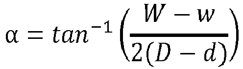
- In accordance with some aspects of the disclosure, the angle, α, defined as:
- In accordance with some aspects of the disclosure, the length D is constrained according to:

- In accordance with some aspects of the disclosure, w = 0.4 mm and is configured to receive any of a 25G, 27G, or 29G needle therein.
- In accordance with some aspects of the disclosure, the angle, α, is preferably between 9° and 90°, and more preferably between 9.5° and 90°.
- In accordance with some aspects of the disclosure, a scrapping or wiping between the needle and the wall forming part of the inner surface of the needle receiving portion is reduced as a value of the angle, α, increases.
- In accordance with some aspects of the disclosure, the needle receiving portion comprises the open proximal end and a distal end, with the wall of the needle receiving portion tapering inward as the needle receiving portion progresses from the open proximal end to the distal end.
- In accordance with some aspects of the disclosure, the tip portion is positioned at the distal end of the needle receiving portion, with the tip portion having an inner diameter larger than an outer diameter of the needle.
- In accordance with some aspects of the disclosure, the tip portion of the needle receiving portion has a constant inner diameter.
- In accordance with some aspects of the disclosure, the tip portion of the needle receiving portion houses a distal needle tip when the needle shield is mounted to the barrel.
- In accordance with some aspects of the disclosure, the hollow cavity includes a barrel end storage portion configured to receive the barrel end portion.
- In accordance with some aspects of the disclosure, the compliant material comprises rubber.
- In accordance with some aspects of the disclosure, the needle shield comprises a rigid outer surface positioned about the compliant material.
-
-
FIG. 1 is a front view of a prefilled syringe, according to an embodiment of the disclosure; -
FIG. 2 is a cross-sectional view taken along line A-A ofFIG. 1 ; -
FIG. 3 is an enlarged front view of a needle shield used for the prefilled syringe ofFIGS. 1 and2 ; -
FIG. 4 is a cross-sectional view taken along line B-B ofFIG. 3 , according to an embodiment of the disclosure; and -
FIG. 5 illustrates the cross-sectional view ofFIG. 4 with the needle shield coupled to a prefilled syringe and covering a needle. - The following description is provided to enable those skilled in the art to make and use the described embodiments contemplated for carrying out the invention. Various modifications, equivalents, variations, and alternatives, however, will remain readily apparent to those skilled in the art. Any and all such modifications, variations, equivalents, and alternatives are intended to fall within the spirit and scope of the present invention.
- For purposes of the description hereinafter, the terms "upper", "lower", "right", "left", "vertical", "horizontal", "top", "bottom", "lateral", "longitudinal", and derivatives thereof shall relate to the invention as it is oriented in the drawing figures. However, it is to be understood that the invention may assume various alternative variations, except where expressly specified to the contrary. It is also to be understood that the specific devices illustrated in the attached drawings, and described in the following specification, are simply exemplary embodiments of the invention. Hence, specific dimensions and other physical characteristics related to the embodiments disclosed herein are not to be considered as limiting.
- In the present disclosure, the distal end of a component or of a device means the end furthest away from the hand of the user and the proximal end means the end closest to the hand of the user, when the component or device is in the use position, i.e., when the user is holding a syringe in preparation for or during use. Similarly, in this application, the terms "in the distal direction" and "distally" mean in the direction toward the distal tip of the syringe, and the terms "in the proximal direction" and "proximally" mean in the direction opposite the direction of the distal tip of the syringe.
- Aspects and embodiments of the disclosure are directed to a prefilled or prefillable syringe and an associated needle shield configured to inhibit corrosion on the syringe needle.
- Referring to
FIGS. 1 and2 , shown is a non-limiting embodiment of asyringe 10, such as a prefilled syringe for example, with which aspects or embodiments of the disclosure may be implemented. The prefilledsyringe 10 includes a syringe assembly (i.e., a barrel with a puncture needle mounted with a cap) 12 and aplunger 14. Theplunger 14 is stored in thesyringe assembly 12 and slideable within thesyringe assembly 12 in a liquid-tight manner. A medicament or other fluid is filled in a volume orchamber 15 formed by thesyringe assembly 12 and theplunger 14. - According to aspects of the disclosure, the
syringe assembly 12 includes abarrel 16, aneedle shield 18 mounted to thebarrel 16, and aneedle 20 retained by thebarrel 16. Thebarrel 16 includes abarrel body portion 22 that defines thechamber 15 within which the medicament or other fluid is contained, a cylindrical (hollow)barrel end portion 24 provided at the distal end of thebarrel body portion 22, and aflange 26 provided at a proximal end of thebarrel body portion 22. Thebarrel end portion 24 projects forward from a distal end 28 (shoulder portion) of thebarrel body portion 22, and has a hollow cylindrical shape having a diameter smaller than that of thebarrel body portion 22. Aproximal end 30 of theneedle 20 is fixedly inserted into the hollow portion of thebarrel end portion 24 and may be fixed to thebarrel end portion 24 with an adhesive, by thermal welding, or the like. Theneedle 20 is configured as a hollow needle (i.e., a lumen formed therein) that includes aneedle tip 32 at adistal end 34 of theneedle 20. Theneedle 20 may be formed of a suitable metal material, with stainless steel being an example. The hollow inside of theneedle 20 communicates with the inner volume of thebarrel 16. - As illustrated in
FIGS. 1 and2 , theplunger 14 is formed of an elongate plunger rod 36 (more generally "plunger rod 36," as used hereafter) and a plunger head or stopper 48. Theplunger rod 36 may include amain body 38 extending between a plungerproximal end 40 and a plungerdistal end 42. In some embodiments, themain body 38 may include a plurality of elongate vanes orwalls 44 extending axially along a length thereof between the plungerproximal end 40 and the plungerdistal end 42. Athumb press 46 is positioned at the plungerproximal end 40 that may be engaged by a thumb (or other finger) of the user to apply a distally directed force to theplunger 14 to move theplunger rod 36 with respect to thebarrel 16. Astopper 48 ofplunger 14 is positioned at the plungerdistal end 42 so as to be movable along with theplunger rod 36 within thechamber 15 ofbarrel 16. In some embodiments, one or more extension members 50 (e.g., disc-shaped flanges) are positioned at the plungerdistal end 42 that are configured to mate with thestopper 48. In other embodiments, the plungerdistal end 42 may include a female receptacle formed therein that is configured to receive and connect to a protrusion (e.g., pin) extending out proximally from thestopper 48, with the protrusion and receptacle engaging via threading, for example. - Referring still to
FIGS. 1 and2 and now also toFIGS. 3-5 , according to aspects of the disclosure, theneedle shield 18 is configured to be mounted to thebarrel 16 via coupling of theneedle shield 18 to thebarrel end portion 24 of thebarrel 16. Theneedle shield 18 may be structured such that at least a portion of anouter surface 52 thereof is formed of a rigid or semirigid material (e.g., a resin such as a polypropylene, a polyethylene, a polystyrene, a polyamide, a polycarbonate, or a polyvinyl chloride) that provides structure to theneedle shield 18. In some embodiments, aflange 54 may be provided on theouter surface 52 at aproximal end 56 of theneedle shield 18, with theflange 54 providing for gripping of theneedle shield 18 to enable placement on thebarrel 16 and/or removal from thebarrel 16. Theneedle shield 18 also includes acompliant material 58 that forms an inner member 60 of theneedle shield 18. The inner member 60 surrounds the needle 20 (whenneedle shield 18 is coupled to barrel 16) and may also present a mating surface for thebarrel end portion 24. Thecompliant material 58 may be provided as rubber (e.g., butyl rubber, isoprene rubber, latex rubber, silicone rubber) or another elastomeric material. - According to aspects of the disclosure, the
compliant material 58 of theneedle shield 18 may be characterized as defining or including a closeddistal end portion 62, an openproximal end portion 64, and ahollow cavity 66 that includes a barrelend storage portion 68 and aneedle storage portion 70. The openproximal end portion 64 defines an opening that allows for positioning of theneedle shield 18 onto thebarrel end portion 24 ofsyringe assembly 12. Thebarrel end portion 24 may be introduced through openproximal end portion 64 and positioned within the barrelend storage portion 68, with thebarrel end portion 24 sized to form a tight fit within the barrelend storage portion 68 to ensure engagement of the needle shield to thebarrel 16. - The
needle storage portion 70 is sized to receive theneedle 20 therein, to provide protection to theneedle 20 once theneedle shield 18 is coupled tobarrel 16. According to embodiments of the disclosure, theneedle storage portion 70 has an inner diameter that tapers as theneedle storage portion 70 extends from itsproximal end 74 to itsdistal end 76. In some embodiments, theproximal end 74 of theneedle storage portion 70 may be formed as a tapered portion having a diameter that reduces proximally to distally to prevent the insertion of theneedle 20 into thecompliant material 58 and securely guide theneedle 20 distally. Thedistal end 76 of theneedle storage portion 70 is formed with a smalldiameter tip portion 78 having an inner diameter, w, slightly larger than the outer diameter of theneedle 20, with thetip portion 78 having a constant inner diameter. - In some embodiments, the
hollow cavity 66 ofneedle shield 18 is configured such that, when thebarrel end portion 24 of thebarrel 16 is inserted into theneedle shield 18 and is received in the barrelend storage portion 68 of theneedle shield 18, theneedle tip 32 of theneedle 20 enters the smalldiameter tip portion 78 of theneedle storage portion 70 but does not protrude therethrough so as to reach thecompliant material 58 of closeddistal end portion 62 that is positioned distally from the smalldiameter tip portion 78 of the needle storage portion 70 - i.e., theneedle tip 32 does not puncture and extend intocompliant material 58. Accordingly, contact between theneedle tip 32 and thecompliant material 58 is reduced or eliminated, and this reduction in contact between theneedle tip 32 and thecompliant material 58 may serve to prevent corrosion of theneedle 20 that might occur responsive to chloride or other chemical species leaching from the compliant material 58 (i.e., rubber) and agglomerating on theneedle 20 to cause corrosion thereof. - In accordance with other embodiments of the disclosure, a portion of the
compliant material 58 distal from theneedle storage portion 70 may be termed as aneedle receiving portion 80 that allows for the insertion of thetip 32 of theneedle 20 therein when theneedle 20 is stored in theneedle storage portion 70. When theneedle shield 18 is mounted to thebarrel end portion 24 of thebarrel 16 and the barrelend storage portion 68 and thebarrel 16 are engaged with each other, the needle may be stored withneedle storage portion 70 and theneedle tip 32 may protrude into and through smalldiameter tip portion 78 so as to be inserted and sealed in theneedle receiving portion 80 of theneedle shield 18. - According to aspects of the disclosure, the
needle shield 18 is designed to minimize the risk of scrapping and/or wiping between theneedle 20 and the inner surface of the needle shield 18 (i.e., inner surface of a portion of compliant material 58) during needle shield assembly, and to minimize the risk to create an undesired confinement zone/cavity between theneedle shield 18 and theneedle 20 in the area of theneedle tip 32 during shelf-life. In order to achieve these results, theneedle shield 18 is constructed to control dimensional ratios between theneedle 20 and theneedle shield 18. - Referring now to
FIGS. 4 and5 , features/dimensions of thehollow cavity 66 ofneedle shield 18 are shown that may be controlled to minimize the risk of scrapping/wiping between theneedle 20 and the inner surface of theneedle shield 18. The features/dimensions of thehollow cavity 66 that may be selectively controlled include: a width, W, of thehollow cavity 66 at an opening ofneedle storage portion 70 that is dependent on the outer diameter of the barrel end portion 24 (lower than the outer diameter of the barrel body portion 22); a width, w, of the smalldiameter tip portion 78; a length, D, of theneedle storage portion 70; a length, d, of the smalldiameter tip portion 78; and an angle, alpha (α), of aninner wall 82 of thecompliant material 58 that forms theneedle storage portion 70 ofcavity 66 as thewall 82 tapers from theproximal end 74 ofneedle storage portion 70 to thedistal end 76 ofneedle storage portion 70, with the angle, α, measured from alongitudinal axis 84 of theneedle shield 18. As indicated above, the dimensions of the features/dimensions of theneedle storage portion 70 ofneedle shield 18 are controlled based on the dimensions of theneedle 20, with theneedle 20 defined by: a length, L, of the needle between theneedle tip 32 and the basis of theneedle storage portion 70; a length, /, of a bevel of the needle atneedle tip 32; and an outer diameter or gauge of theneedle 20. According to embodiments, needle shields 18 may be provided that are useable with needles of differing configurations, including needles of differing lengths and gauges, including 1/2" (12.7mm) and 5/8" (15.875mm) length needles, and 25G, 27G and 29G needles, as examples. - According to aspects of the disclosure, scrapping/wiping between the
needle 20 and the inner surface of the compliant material 58 (including wall 82) may be minimized when theneedle 20 and the inner surface of thewall 82 are perpendicular- which is achieved via (1) increasing a value of the angle, α, or (2) reducing of the distance between the proximal part of the needle shield 18 (at opening of needle storage portion 70) and the inner distal part of the shield (at distal end of small diameter tip portion 78) where theneedle 20 is pricked. - According to embodiments, in order to minimize scrapping/wiping between the
needle 20 and the inner surface of thewall 82 while maintaining the sterility of the proximal part of theneedle 20 during storage/transport, theneedle shield 18 is configured to have an increased angle, α. In optimizing the angle, α, to minimize scrapping/wiping between theneedle 20 and the inner surface of thewall 82, α may have a maximum value of 90° (where scrapping is minimized) and a minimum value of 8°, more preferably 9°, and even more preferably 9.5° (where scrapping is increased). The angle, α, may be defined according to:
needle 20, such as w = 0.4mm for 25G, 27G and 29G needles) and L-l > D, so thatneedle 20 is pricked inside theneedle shield 18. - Provided here below are examples of needle shield configurations that may be utilized with standard length/gauge needles. While needle shield configurations for 1/2" and 5/8" length needles with a gauge of 25G, 27G or 29G are provided as specific examples for purposes of better illustrating aspects of the disclosure, it is recognized that needle shield configurations may be provided for needles covering all kinds of parenteral injections, including hypodermic needles or various configurations, with such needles having various lengths and/or gauges. As described above, the angle, α, may be controlled to reduce scrapping/wiping between the
needle 20 and the inner surface of the compliant material 58 (i.e., of wall 82), while maintaining the sterility of the proximal part of theneedle 20 during storage/transport. Table 1 provides three (3) exemplary needle shields, according to non-limiting examples of the disclosure.TABLE 1 Shield Design 5/8" needle (25G) 5/8" needle (27G) 1/2" needle (25G) w (mm) 0.4 0.4 0.4 W (mm) 3.81 3.81 3.8 d (mm) 2 1.6 1.6 D (mm) 13.94 11.71 9.15 α (rad) 0.141838 0.167073 0.221472 α (deg) 8.126743 9.545013 12.68941 - It is recognized that needle shields having differing configurations from those indicated above may be provided to accommodate needles of differing structures, including needles of different lengths and gauges. In such embodiments, the needle shield will have an angle, α, that reduces scrapping/wiping between the needle and the inner surface of the shield, while maintaining the sterility of the proximal part of the needle during storage/transport.
- Beneficially, embodiments of the invention thus provide a needle shield that is configured to reduce the risk of corrosion developing on the needle. The needle shield includes an internal cavity shaped and dimensioned to accommodate receiving of the needle therein, while reducing contact between the needle and a compliant material of the needle shield.
- Although the present disclosure has been described in detail for the purpose of illustration based on what is currently considered to be the most practical and preferred embodiments or aspects, it is to be understood that such detail is solely for that purpose and that the present disclosure is not limited to the disclosed embodiments or aspects, but, on the contrary, is intended to cover modifications and equivalent arrangements that are within the spirit and scope of the appended claims. For example, it is to be understood that the present disclosure contemplates that, to the extent possible, one or more features of any embodiment may be combined with one or more features of any other embodiment.
Claims (13)
- A prefilled or prefillable syringe, the syringe comprising:a syringe assembly including:a barrel having a barrel distal end and a barrel proximal end and defining a chamber, the barrel including a barrel end portion at the barrel distal end;a needle having a needle tip at a distal end of the needle and having a proximal end fixedly inserted into the barrel end portion; anda needle shield mounted to the barrel via the barrel end portion, so as to be positioned over the needle; anda plunger received within the chamber of the barrel and axially movable therein;wherein the needle shield comprises a compliant material at least partially defining a hollow cavity therein, the hollow cavity including a needle receiving portion within which the needle is positioned when the needle shield is mounted to the barrel,characterized in that a wall forming part of an inner surface of the needle receiving portion has an angle, α, between 8° and 90° relative to a longitudinal axis of the needle shield.
- The syringe of claim 1, wherein the angle, α, defined as:

- The syringe of claim 2, wherein the length D is constrained according to:

- The syringe of claim 2 or claim 3, wherein w = 0.4 mm and is configured to receive any of a 25G, 27G, or 29G needle therein.
- The syringe of any of claims 1-4, wherein the angle, α, is preferably between 9° and 90°, and more preferably between 9.5° and 90°.
- The syringe of any of claims 1-5, wherein a scrapping or wiping between the needle and the wall forming part of the inner surface of the needle receiving portion is reduced as a value of the angle, α, increases.
- The syringe of any of claims 1-6, wherein the needle receiving portion comprises the open proximal end and a distal end, with the wall of the needle receiving portion tapering inward as the needle receiving portion progresses from the open proximal end to the distal end.
- The syringe of claim 7, wherein the tip portion is positioned at the distal end of the needle receiving portion, with the tip portion having an inner diameter larger than an outer diameter of the needle.
- The syringe of claim 8, wherein the tip portion of the needle receiving portion has a constant inner diameter.
- The syringe of claim 8 or claim 9 wherein the tip portion of the needle receiving portion houses a distal needle tip when the needle shield is mounted to the barrel.
- The syringe of any of claims 1-10, wherein the hollow cavity includes a barrel end storage portion configured to receive the barrel end portion.
- The syringe of any of claims 1-11, wherein the compliant material comprises rubber.
- The syringe of any of claims 1-12, wherein the needle shield comprises a rigid outer surface positioned about the compliant material.
Priority Applications (3)
| Application Number | Priority Date | Filing Date | Title |
|---|---|---|---|
| EP23305890.8A EP4473990A1 (en) | 2023-06-05 | 2023-06-05 | Syringe needle shield for minimizing needle corrosion |
| PCT/EP2024/065313 WO2024251726A1 (en) | 2023-06-05 | 2024-06-04 | Syringe needle shield for minimizing needle corrosion |
| CN202480037361.5A CN121311266A (en) | 2023-06-05 | 2024-06-04 | Syringe needle sheath for minimizing needle corrosion |
Applications Claiming Priority (1)
| Application Number | Priority Date | Filing Date | Title |
|---|---|---|---|
| EP23305890.8A EP4473990A1 (en) | 2023-06-05 | 2023-06-05 | Syringe needle shield for minimizing needle corrosion |
Publications (1)
| Publication Number | Publication Date |
|---|---|
| EP4473990A1 true EP4473990A1 (en) | 2024-12-11 |
Family
ID=87047827
Family Applications (1)
| Application Number | Title | Priority Date | Filing Date |
|---|---|---|---|
| EP23305890.8A Pending EP4473990A1 (en) | 2023-06-05 | 2023-06-05 | Syringe needle shield for minimizing needle corrosion |
Country Status (3)
| Country | Link |
|---|---|
| EP (1) | EP4473990A1 (en) |
| CN (1) | CN121311266A (en) |
| WO (1) | WO2024251726A1 (en) |
Citations (5)
| Publication number | Priority date | Publication date | Assignee | Title |
|---|---|---|---|---|
| US4986818A (en) * | 1990-03-30 | 1991-01-22 | Becton, Dickinson And Company | Syringe assembly |
| US20010044608A1 (en) * | 1998-07-31 | 2001-11-22 | Odell Robert B. | Needle shield for a prefillable syringe |
| US20080215013A1 (en) * | 2007-03-02 | 2008-09-04 | Becton Dickison France S.A.S. | Shield for covering the extremity of an administration device or assembly, an administration assembly and an administration device |
| EP3192549A1 (en) * | 2014-09-11 | 2017-07-19 | Terumo Kabushiki Kaisha | Syringe assembly, syringe assembly packaging, outer cylinder seal cap, and prefilled syringe |
| US20180344942A1 (en) * | 2015-09-23 | 2018-12-06 | Aptar Stelmi Sas | Dispensing assembly having a syringe and a needle guard |
-
2023
- 2023-06-05 EP EP23305890.8A patent/EP4473990A1/en active Pending
-
2024
- 2024-06-04 CN CN202480037361.5A patent/CN121311266A/en active Pending
- 2024-06-04 WO PCT/EP2024/065313 patent/WO2024251726A1/en not_active Ceased
Patent Citations (5)
| Publication number | Priority date | Publication date | Assignee | Title |
|---|---|---|---|---|
| US4986818A (en) * | 1990-03-30 | 1991-01-22 | Becton, Dickinson And Company | Syringe assembly |
| US20010044608A1 (en) * | 1998-07-31 | 2001-11-22 | Odell Robert B. | Needle shield for a prefillable syringe |
| US20080215013A1 (en) * | 2007-03-02 | 2008-09-04 | Becton Dickison France S.A.S. | Shield for covering the extremity of an administration device or assembly, an administration assembly and an administration device |
| EP3192549A1 (en) * | 2014-09-11 | 2017-07-19 | Terumo Kabushiki Kaisha | Syringe assembly, syringe assembly packaging, outer cylinder seal cap, and prefilled syringe |
| US20180344942A1 (en) * | 2015-09-23 | 2018-12-06 | Aptar Stelmi Sas | Dispensing assembly having a syringe and a needle guard |
Also Published As
| Publication number | Publication date |
|---|---|
| CN121311266A (en) | 2026-01-09 |
| WO2024251726A1 (en) | 2024-12-12 |
Similar Documents
| Publication | Publication Date | Title |
|---|---|---|
| EP0637443B1 (en) | Drug access assembly for vials and ampules | |
| US4969883A (en) | Medicament vial end cap membrane piercing device | |
| JP6302005B2 (en) | Needle protection device | |
| EP3302657B1 (en) | Disposable pen needle with abbreviated non-patient end, and reusable pen interface | |
| EP3793504B1 (en) | Connector for connecting a medical injection device to a container | |
| IL219535A (en) | Syringes | |
| US12285388B2 (en) | Syringe assembly and adapter member | |
| EP1421961A2 (en) | Self-aligning shield for syringe | |
| CN103052415B (en) | For the system and method for injector for medical purpose | |
| EP0523091B1 (en) | Applicator having two cannulas | |
| US3890972A (en) | Syringe injector with pop-top cap | |
| WO2024251726A1 (en) | Syringe needle shield for minimizing needle corrosion | |
| US12551630B2 (en) | Connector for connecting a medical injection device to a container and assembly comprising said connector and medical injection device | |
| EP4454683A1 (en) | Pfas-free syringe plunger stopper with curved inter-rib region | |
| EP4729096A1 (en) | Needle cover for medical injection device | |
| EP4596004A1 (en) | Needle cover for medical injection device | |
| CA2022166A1 (en) | Medicament vial end cap membrane piercing device | |
| HK1000504B (en) | Applicator having two cannulas |
Legal Events
| Date | Code | Title | Description |
|---|---|---|---|
| PUAI | Public reference made under article 153(3) epc to a published international application that has entered the european phase |
Free format text: ORIGINAL CODE: 0009012 |
|
| STAA | Information on the status of an ep patent application or granted ep patent |
Free format text: STATUS: THE APPLICATION HAS BEEN PUBLISHED |
|
| AK | Designated contracting states |
Kind code of ref document: A1 Designated state(s): AL AT BE BG CH CY CZ DE DK EE ES FI FR GB GR HR HU IE IS IT LI LT LU LV MC ME MK MT NL NO PL PT RO RS SE SI SK SM TR |
|
| STAA | Information on the status of an ep patent application or granted ep patent |
Free format text: STATUS: REQUEST FOR EXAMINATION WAS MADE |
|
| 17P | Request for examination filed |
Effective date: 20250610 |