EP4473934A2 - Retractable shaver bur - Google Patents
Retractable shaver bur Download PDFInfo
- Publication number
- EP4473934A2 EP4473934A2 EP24209590.9A EP24209590A EP4473934A2 EP 4473934 A2 EP4473934 A2 EP 4473934A2 EP 24209590 A EP24209590 A EP 24209590A EP 4473934 A2 EP4473934 A2 EP 4473934A2
- Authority
- EP
- European Patent Office
- Prior art keywords
- bur
- hub
- shaver
- deployment mechanism
- tube
- Prior art date
- Legal status (The legal status is an assumption and is not a legal conclusion. Google has not performed a legal analysis and makes no representation as to the accuracy of the status listed.)
- Granted
Links
Images

Classifications
-
- A—HUMAN NECESSITIES
- A61—MEDICAL OR VETERINARY SCIENCE; HYGIENE
- A61B—DIAGNOSIS; SURGERY; IDENTIFICATION
- A61B17/00—Surgical instruments, devices or methods
- A61B17/32—Surgical cutting instruments
- A61B17/320016—Endoscopic cutting instruments, e.g. arthroscopes, resectoscopes
- A61B17/32002—Endoscopic cutting instruments, e.g. arthroscopes, resectoscopes with continuously rotating, oscillating or reciprocating cutting instruments
-
- A—HUMAN NECESSITIES
- A61—MEDICAL OR VETERINARY SCIENCE; HYGIENE
- A61B—DIAGNOSIS; SURGERY; IDENTIFICATION
- A61B17/00—Surgical instruments, devices or methods
- A61B17/16—Instruments for performing osteoclasis; Drills or chisels for bones; Trepans
- A61B17/1657—Bone breaking devices
-
- A—HUMAN NECESSITIES
- A61—MEDICAL OR VETERINARY SCIENCE; HYGIENE
- A61B—DIAGNOSIS; SURGERY; IDENTIFICATION
- A61B17/00—Surgical instruments, devices or methods
- A61B17/16—Instruments for performing osteoclasis; Drills or chisels for bones; Trepans
- A61B17/1604—Chisels; Rongeurs; Punches; Stamps
-
- A—HUMAN NECESSITIES
- A61—MEDICAL OR VETERINARY SCIENCE; HYGIENE
- A61B—DIAGNOSIS; SURGERY; IDENTIFICATION
- A61B17/00—Surgical instruments, devices or methods
- A61B17/16—Instruments for performing osteoclasis; Drills or chisels for bones; Trepans
- A61B17/1613—Component parts
- A61B17/1633—Sleeves, i.e. non-rotating parts surrounding the bit shaft, e.g. the sleeve forming a single unit with the bit shaft
-
- A—HUMAN NECESSITIES
- A61—MEDICAL OR VETERINARY SCIENCE; HYGIENE
- A61B—DIAGNOSIS; SURGERY; IDENTIFICATION
- A61B17/00—Surgical instruments, devices or methods
- A61B17/32—Surgical cutting instruments
-
- A—HUMAN NECESSITIES
- A61—MEDICAL OR VETERINARY SCIENCE; HYGIENE
- A61B—DIAGNOSIS; SURGERY; IDENTIFICATION
- A61B90/00—Instruments, implements or accessories specially adapted for surgery or diagnosis and not covered by any of the groups A61B1/00 - A61B50/00, e.g. for luxation treatment or for protecting wound edges
- A61B90/90—Identification means for patients or instruments, e.g. tags
-
- A—HUMAN NECESSITIES
- A61—MEDICAL OR VETERINARY SCIENCE; HYGIENE
- A61B—DIAGNOSIS; SURGERY; IDENTIFICATION
- A61B90/00—Instruments, implements or accessories specially adapted for surgery or diagnosis and not covered by any of the groups A61B1/00 - A61B50/00, e.g. for luxation treatment or for protecting wound edges
- A61B90/90—Identification means for patients or instruments, e.g. tags
- A61B90/98—Identification means for patients or instruments, e.g. tags using electromagnetic means, e.g. transponders
-
- A—HUMAN NECESSITIES
- A61—MEDICAL OR VETERINARY SCIENCE; HYGIENE
- A61B—DIAGNOSIS; SURGERY; IDENTIFICATION
- A61B17/00—Surgical instruments, devices or methods
- A61B2017/00831—Material properties
- A61B2017/00876—Material properties magnetic
-
- A—HUMAN NECESSITIES
- A61—MEDICAL OR VETERINARY SCIENCE; HYGIENE
- A61B—DIAGNOSIS; SURGERY; IDENTIFICATION
- A61B17/00—Surgical instruments, devices or methods
- A61B17/32—Surgical cutting instruments
- A61B17/320016—Endoscopic cutting instruments, e.g. arthroscopes, resectoscopes
- A61B17/32002—Endoscopic cutting instruments, e.g. arthroscopes, resectoscopes with continuously rotating, oscillating or reciprocating cutting instruments
- A61B2017/320028—Endoscopic cutting instruments, e.g. arthroscopes, resectoscopes with continuously rotating, oscillating or reciprocating cutting instruments with reciprocating movements
-
- A—HUMAN NECESSITIES
- A61—MEDICAL OR VETERINARY SCIENCE; HYGIENE
- A61B—DIAGNOSIS; SURGERY; IDENTIFICATION
- A61B17/00—Surgical instruments, devices or methods
- A61B17/32—Surgical cutting instruments
- A61B17/320016—Endoscopic cutting instruments, e.g. arthroscopes, resectoscopes
- A61B17/32002—Endoscopic cutting instruments, e.g. arthroscopes, resectoscopes with continuously rotating, oscillating or reciprocating cutting instruments
- A61B2017/320032—Details of the rotating or oscillating shaft, e.g. using a flexible shaft
-
- A—HUMAN NECESSITIES
- A61—MEDICAL OR VETERINARY SCIENCE; HYGIENE
- A61B—DIAGNOSIS; SURGERY; IDENTIFICATION
- A61B90/00—Instruments, implements or accessories specially adapted for surgery or diagnosis and not covered by any of the groups A61B1/00 - A61B50/00, e.g. for luxation treatment or for protecting wound edges
- A61B90/08—Accessories or related features not otherwise provided for
- A61B2090/0801—Prevention of accidental cutting or pricking
- A61B2090/08021—Prevention of accidental cutting or pricking of the patient or his organs
Definitions
- the present invention relates to a surgical cutting device and, more particularly, to a shaver bur having a retractable bur tip.
- the bur tip In use, the bur tip will spin forward, backward, or oscillate while the outer assembly remains stationary. In traditional shaver burs, the bur tip is permanently exposed. As a result, during arthroscopic procedures, the sharp cutting edges of the bur trip occasionally and unintentionally contact articular surfaces within the joint space. This contact can cause damage and injury to the patient at the surgical site.
- a shaver bur includes an inner assembly having an inner hub with an inner tube extending distally therefrom.
- the inner tube terminates in a distal bur tip.
- the shaver bur also includes an outer assembly having an outer hub with an outer tube extending distally therefrom.
- the inner tube is moveable within the outer tube between a retracted position and an extended position.
- the shaver bur additionally includes a deployment mechanism connected to the outer hub.
- the deployment mechanism is movable in a first direction and a second direction. Moving the deployment mechanism in the first direction moves the inner tube to the extended position and moving the deployment mechanism in the second direction moves the inner tube to the retracted position.
- a shaver bur includes an inner assembly having an inner hub with an inner tube extending distally therefrom.
- the inner tube terminates in a distal bur tip.
- the shaver bur also includes an outer assembly having an outer hub with an outer tube extending distally therefrom.
- the inner tube is moveable within the outer tube between a retracted position and an extended position.
- the shaver bur additionally includes a magnet retainer connected between the inner hub and the outer hub.
- the shaver bur has a deployment mechanism connected to the outer hub.
- the deployment mechanism is movable in a first direction and a second direction. Moving the deployment mechanism in the first direction moves the inner tube to the extended position and moving the deployment mechanism in the second direction moves the inner tube to the retracted position. In addition, moving the deployment mechanism in the second direction moves the deployment mechanism against the magnet retainer.
- a method for resecting bone includes the steps of: (i) providing a shaver bur including an inner assembly having an inner hub with an inner tube extending distally therefrom, the inner tube terminating in a distal bur tip, an outer assembly having an outer hub with an outer tube extending distally therefrom, wherein the inner tube is within the outer tube, and a deployment mechanism connected to the outer hub; (ii) moving the deployment mechanism in a first direction, causing the distal bur tip to extend from the outer tube; (iii) resecting bone with the distal bur tip; and (iv) moving the deployment mechanism is a second direction, causing the distal bur tip to be retracted into the outer tube.
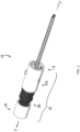
- FIG. 1 a perspective view schematic representation of a retractable shaver bur 10, according to an embodiment.
- the shaver bur 10 includes a proximal outer hub assembly 12 with an outer tube 14 (see, also FIG. 3 ) extending distally therefrom along a central longitudinal y - y axis.
- the outer hub assembly 12 extends to and comprises a proximal end 16 and the outer tube 14 extends to and comprises a distal end 18 of the shaver bur 10, as shown in FIG. 1 .
- the shaver bur 10 comprises a proximal inner assembly 20 coupled to a distal outer assembly 22.
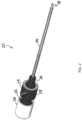
- FIG. 2 there is shown a perspective view schematic representation of the inner assembly 20 of the shaver bur 10, according to an embodiment.
- the inner assembly 20 includes an inner hub 24 connected to a proximal end cap 26.
- the proximal end cap 26 is removably attached to the inner hub 24.
- the proximal end cap 26 is bonded to the inner hub 24.
- the inner hub 24 and the proximal end cap 26 are substantially cylindrical.
- the inner hub 24 comprises a cylindrical central body 28 with a central connecting tube 30 extending therefrom in the distal direction.
- the inner hub 24 also includes a key portion 32 extending from the central body 28 in the proximal direction.
- the key portion 32 includes one or more features 34 for connecting the inner hub 24 to the proximal end cap 26 ( FIG. 4 ).
- the inner hub 24 is connected to an inner tube 36.
- the central connecting tube 30 extending distally from the inner hub 24 is cannulated and configured or otherwise adapted to receive the inner tube 36, as shown in FIG. 2 .
- the inner tube 36 is solid.
- the inner tube 36 can be composed of steel and/or other similar hard metals.
- the inner tube 36 extends to and includes a distal bur tip 38. The bur tip 38 is used to shave or resect bone inside a joint during arthroscopic procedures.
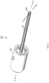
- the outer assembly 22 includes a cylindrical outer hub 40 connected to the cannulated outer tube 14.
- the cannulated outer tube 14 extends distally from the outer hub 40.
- the outer hub 40 is bonded to the cannulated outer tube 14.
- the cannulated outer tube 14 comprises an open distal end 42.
- the open distal end 42 is angled such that a plane x - x extending over the open distal end 42 is at an angle relative to the central longitudinal y - y axis.
- the plane a - a is at an angle less than 90 degrees relative to the central longitudinal y - y axis.
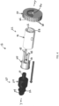
- the outer hub assembly 12 includes the inner hub 24 of the inner assembly 20 and the outer hub 40 of the outer assembly 22. Between the inner hub 24 and the outer hub 40 is a magnet retainer 44.
- the magnet retainer 44 is cylindrical with a central bore 46 extending therethrough.
- the magnet retainer 44 additionally comprises one or more stems 48 (e.g., rods) extending distally therefrom. As shown in FIG. 4 , the stems 48 extend from a distal end 50 of the magnet retainer 44 toward the outer hub 40.
- the purpose of the magnetic retainer 44 is to allow for identification of the type of blade or bur used with a handpiece (not shown) connected to the outer hub assembly 12.
- the magnetic retainer 44 can convey information to the handpiece and connected control system (not shown) so that appropriate signals may be generated by the control system to optimize attachments for certain procedures requiring varying speeds and torques.
- the signals may also alter the operation of buttons on the handpiece (e.g., toggle, momentary on/off, etc.).
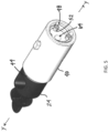
- FIG. 5 there is shown a perspective view schematic representation of the inner hub 24 coupled to the outer hub 40, according to an embodiment.
- the inner hub 24 is coupled to the outer hub 40 with the magnet retainer 44 therebetween.
- the outer hub 40 comprises one or more slots 52 extending at least partially therethrough along the central longitudinal y - y axis ( FIG. 4 ). In the depicted embodiment, the slots 52 extend entirely through the outer hub 40.
- the central connecting tube 30 of the inner hub 24 extends through the central bore 46 of the magnet retainer 44 ( FIG. 4 ).
- the one or more stems 48 of the magnet retainer 44 extend into the one or more slots 52 of the outer hub 40.
- the outer hub 40 includes a central bore 64 configured or otherwise adapted to receive the inner tube 36.
- the outer hub assembly 12 additionally comprises a deployment mechanism 54.
- the deployment mechanism 54 is a "twist ring.”
- the twist ring 54 is a rotatable circular piece, such as a disk, cap, or plate.
- the twist ring 54 is a rotatable, cylindrical disk with a central bore 56 extending therethrough.
- the twist ring 54 is attached to a distal end 58 of the outer hub 40 and abuts (or is adjacent to) the one or more stems 48 of the magnet retainer 44.
- the twist ring 54 functions to extend and retract the distal bur tip 38 ( FIG. 1 ).
- the twist ring 54 comprises a plurality of ridges 60 extending along its outer circumference 62. The ridges 60 allow a user to get a firm grip on the twist ring 54 to rotate it.
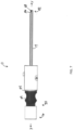
- FIGs. 6 and 7 there are shown side views schematic representations of the shaver bur 10 in a retracted position and an extended position, respectively, according to an embodiment.
- the inner tube 36 with the distal bur tip 38 is retracted and protected within the outer tube 14, as shown in FIG. 6 .
- the twist ring 54 is rotated in a first direction (e.g., counter-clockwise).
- the inner assembly 20 moves axially along the central longitudinal y - y axis toward the distal end 42 of the outer tube 14, sliding the inner tube 36 distally from the outer tube 14.
- the twist ring 54 is rotated in the first direction until the bur tip 38 is exposed and ready for use, as shown in FIG. 7 .
- the twist ring 54 When use of the bur tip 38 is complete, the twist ring 54 is rotated in a second direction (e.g., clockwise). As the twist ring 54 rotates in the second direction, the twist ring 54 pushes against the one or more stems 48, which in turn, engage the inner assembly 20. Specifically, the stems 48 on the magnet retainer 44 are engaged and move axially and proximally along the central longitudinal y - y axis toward the proximal end 16 of the shaver bur 10. The magnet retainer 44 engages the inner hub 24, which is bonded to the inner tube 36. The entire inner assembly 20, including the bur tip 38, moves axially toward the proximal end 16 of the shaver bur 10. As a result, the bur tip 38 is fully retracted within the outer tube 14, as shown in FIG. 7 .
- twist ring 54 allows the user to make fine-tune adjustments, permitting the bur tip to be completely exposed, fully retracted, or at some position therebetween.
- the twist ring 54 may also comprise a knob or other handle-like feature for rotating the twist ring 54.
- the deployment mechanism 54 is a lever or latch assembly that, when moved from a first position to a second position, causes the bur tip 38 to move from the retracted position to the extended position.
- the deployment mechanism 54 is an on/off button or an actuator button that when pressed, moves the bur tip 38 from the retracted position to the extended position.
- the on/off button can operate such that it must be held down in the pressed state to maintain the bur tip 38 in the extended (or retracted) position.
- the deployment mechanism 54 is a release ring that is pulled in the proximal direction to either move the outer tube 14 proximally over the inner tube 36, exposing the bur tip 38 or move the inner tube 36 in the distal direction out from the outer tube 14, exposing the bur tip 38.
- the release ring (and other embodiments of the deployment mechanism 54) can be used in conjunction with a locking mechanism that locks the shaver bur 10 in the retracted and/or extended positions.
- a shaver bur may comprise: an inner assembly having an inner hub with an inner tube extending distally therefrom, the inner tube terminating in a distal bur tip; an outer assembly having an outer hub with an outer tube extending distally therefrom; wherein the inner tube is moveable within the outer tube between a retracted position and an extended position; a deployment mechanism connected to the outer hub, the deployment mechanism movable in a first direction and a second direction; and wherein moving the deployment mechanism in a first direction moves the inner tube to the extended position and moving the deployment mechanism in a second direction moves the inner tube to the retracted position.
- the distal bur tip extends out from the outer tube in the extended position.
- the distal bur tip is within the outer tube in the retracted position.
- the outer tube has a distal end and the distal end is angled relative to a central longitudinal axis extending through the outer tube.
- the deployment mechanism is a disk rotatable in the first direction and the second direction, wherein according to a sixth aspect, the shaver bur may further comprise a plurality of ridges on an outer circumference of the disk.
- the inner hub and the outer hub are substantially cylindrical.
- a shaver bur may comprise: an inner assembly having an inner hub with an inner tube extending distally therefrom, the inner tube terminating in a distal bur tip; an outer assembly having an outer hub with an outer tube extending distally therefrom; wherein the inner tube is moveable within the outer tube between a retracted position and an extended position; a magnet retainer connected between the inner hub and the outer hub; a deployment mechanism connected to the outer hub, the deployment mechanism movable in a first direction and a second direction; wherein moving the deployment mechanism in the first direction moves the inner tube to the extended position and moving the deployment mechanism in the second direction moves the inner tube to the retracted position; and wherein moving the deployment mechanism in the second direction moves the deployment mechanism against the magnet retainer.
- the shaver bur may further comprise one or more slots extending at least partially through the outer hub.
- the shave bur may further comprise one or more stems extending from the magnet retainer.
- each of the one or more stems may extend through one of the one or more slots in the outer hub.
- the deployment mechanism may abut the one or more stems of the magnet retainer.
- the deployment mechanism may be a disk rotatable in the first direction and the second direction.
- a method for resecting bone may comprise the steps of: providing a shaver bur including an inner assembly having an inner hub with an inner tube extending distally therefrom, the inner tube terminating in a distal bur tip, an outer assembly having an outer hub with an outer tube extending distally therefrom, wherein the inner tube is within the outer tube, and a deployment mechanism connected to the outer hub; moving the deployment mechanism in a first direction, causing the distal bur tip to extend from the outer tube; and resecting bone with the distal bur tip.
- the method may further comprise the step of moving the deployment mechanism is a second direction, causing the distal bur tip to be retracted into the outer tube.
- the deployment mechanism may be a disk rotatable in the first direction and the second direction.
- the shaver bur may include a magnet retainer connected between the inner hub and the outer hub.
- the magnet retainer may comprise one or more stems.
- the outer hub may comprise one or more slots extending therethrough, and further wherein each of the one or more stems extends through one of the one or more slots.
- the step of moving the deployment mechanism in a second direction may cause the deployment mechanism to press against the one or more stems of the magnet retainer.
Landscapes
- Health & Medical Sciences (AREA)
- Surgery (AREA)
- Life Sciences & Earth Sciences (AREA)
- Molecular Biology (AREA)
- General Health & Medical Sciences (AREA)
- Veterinary Medicine (AREA)
- Engineering & Computer Science (AREA)
- Biomedical Technology (AREA)
- Heart & Thoracic Surgery (AREA)
- Medical Informatics (AREA)
- Nuclear Medicine, Radiotherapy & Molecular Imaging (AREA)
- Animal Behavior & Ethology (AREA)
- Public Health (AREA)
- Oral & Maxillofacial Surgery (AREA)
- Orthopedic Medicine & Surgery (AREA)
- Pathology (AREA)
- Dentistry (AREA)
- Physics & Mathematics (AREA)
- Electromagnetism (AREA)
- Surgical Instruments (AREA)
- Vehicle Step Arrangements And Article Storage (AREA)
- Passenger Equipment (AREA)
- Dry Shavers And Clippers (AREA)
Abstract
Description
- The present application claims priority to and the benefit of
U.S. Provisional Patent Application Number 62/779,031, filed on December 13, 2018 - The present invention relates to a surgical cutting device and, more particularly, to a shaver bur having a retractable bur tip.
- Shaver burs are surgical cutting instruments having a sharp flute intended to "shave" or resect bone inside the joint during arthroscopic procedures. Surgical shaver burs are comprised of an inner and an outer assembly. The outer assembly is composed of a hollow steel tube, which is bonded to a molded plastic hub on the proximal end and contains a cut out or open hood on the distal end. The inner assembly is housed within the outer assembly and comprises an inner tube. The inner tube is composed of a hollow steel tube, which is bonded to a molded plastic hub on the proximal end and welded to a shaver bur tip on the distal end.
- In use, the bur tip will spin forward, backward, or oscillate while the outer assembly remains stationary. In traditional shaver burs, the bur tip is permanently exposed. As a result, during arthroscopic procedures, the sharp cutting edges of the bur trip occasionally and unintentionally contact articular surfaces within the joint space. This contact can cause damage and injury to the patient at the surgical site.
- Therefore, there is a need for a shaver bur with a protectable bur tip to improve operation conditions.
- Description of the Related Art Section Disclaimer: To the extent that specific patents/publications/products are discussed above in this Description of the Related Art Section or elsewhere in this disclosure, these discussions should not be taken as an admission that the discussed patents/publications/products are prior art for patent law purposes. For example, some or all of the discussed patents/publications/products may not be sufficiently early in time, may not reflect subject matter developed early enough in time and/or may not be sufficiently enabling so as to amount to prior art for patent law purposes. To the extent that specific patents/publications/products are discussed above in this Description of the Related Art Section and/or throughout the application, the descriptions/disclosures of which are all hereby incorporated by reference into this document in their respective entirety(ies).
- The present disclosure is directed to a shaver bur for resecting bone inside the joint in arthroscopic procedures. The shave bur of the present invention is defined in Claim 1. Further advantageous features are set out in the dependent claims.
- According to an aspect related to the invention, a shaver bur includes an inner assembly having an inner hub with an inner tube extending distally therefrom. The inner tube terminates in a distal bur tip. The shaver bur also includes an outer assembly having an outer hub with an outer tube extending distally therefrom. The inner tube is moveable within the outer tube between a retracted position and an extended position. The shaver bur additionally includes a deployment mechanism connected to the outer hub. The deployment mechanism is movable in a first direction and a second direction. Moving the deployment mechanism in the first direction moves the inner tube to the extended position and moving the deployment mechanism in the second direction moves the inner tube to the retracted position.
- According to another aspect related to the invention, a shaver bur includes an inner assembly having an inner hub with an inner tube extending distally therefrom. The inner tube terminates in a distal bur tip. The shaver bur also includes an outer assembly having an outer hub with an outer tube extending distally therefrom. The inner tube is moveable within the outer tube between a retracted position and an extended position. The shaver bur additionally includes a magnet retainer connected between the inner hub and the outer hub. The shaver bur has a deployment mechanism connected to the outer hub. The deployment mechanism is movable in a first direction and a second direction. Moving the deployment mechanism in the first direction moves the inner tube to the extended position and moving the deployment mechanism in the second direction moves the inner tube to the retracted position. In addition, moving the deployment mechanism in the second direction moves the deployment mechanism against the magnet retainer.
- According to yet another aspect related to the invention, a method for resecting bone includes the steps of: (i) providing a shaver bur including an inner assembly having an inner hub with an inner tube extending distally therefrom, the inner tube terminating in a distal bur tip, an outer assembly having an outer hub with an outer tube extending distally therefrom, wherein the inner tube is within the outer tube, and a deployment mechanism connected to the outer hub; (ii) moving the deployment mechanism in a first direction, causing the distal bur tip to extend from the outer tube; (iii) resecting bone with the distal bur tip; and (iv) moving the deployment mechanism is a second direction, causing the distal bur tip to be retracted into the outer tube.
- The present invention will be more fully understood and appreciated by reading the following Detailed Description in conjunction with the accompanying drawings. The accompanying drawings illustrate only typical embodiments of the disclosed subject matter and are therefore not to be considered limiting of its scope, for the disclosed subject matter may admit to other equally effective embodiments. Reference is now made briefly to the accompanying drawings, in which:
-
FIG. 1 is a perspective view schematic representation of the shaver bur, according to an embodiment; -
FIG. 2 is a perspective view schematic representation of the inner assembly of the shaver bur, according to an embodiment; -
FIG. 3 is a perspective view schematic representation of the outer assembly of the shave bur, according to an embodiment; -
FIG. 4 is an exploded perspective view schematic representation of the outer hub assembly of the shaver bur, according to an embodiment; -
FIG. 5 is a perspective view schematic representation of the inner hub coupled to the outer hub, according to an embodiment; -
FIG. 6 is a side view schematic representation of the shaver bur in a retracted position, according to an embodiment; and -
FIG. 7 is a side view schematic representation of the shaver bur in an extended position, according to an embodiment. - Referring now to the drawings, wherein like reference numerals refer to like parts throughout, there is seen in
FIG. 1 , a perspective view schematic representation of aretractable shaver bur 10, according to an embodiment. Theshaver bur 10 includes a proximalouter hub assembly 12 with an outer tube 14 (see, alsoFIG. 3 ) extending distally therefrom along a central longitudinal y - y axis. Theouter hub assembly 12 extends to and comprises a proximal end 16 and theouter tube 14 extends to and comprises a distal end 18 of theshaver bur 10, as shown inFIG. 1 . Theshaver bur 10 comprises a proximalinner assembly 20 coupled to a distalouter assembly 22. - Turning now to
FIG. 2 , there is shown a perspective view schematic representation of theinner assembly 20 of theshaver bur 10, according to an embodiment. Theinner assembly 20 includes aninner hub 24 connected to aproximal end cap 26. In an embodiment, theproximal end cap 26 is removably attached to theinner hub 24. In an alternative embodiment, theproximal end cap 26 is bonded to theinner hub 24. As shown inFIG. 2 , theinner hub 24 and theproximal end cap 26 are substantially cylindrical. - Still referring to
FIG. 2 , theinner hub 24 comprises a cylindricalcentral body 28 with acentral connecting tube 30 extending therefrom in the distal direction. Theinner hub 24 also includes akey portion 32 extending from thecentral body 28 in the proximal direction. Thekey portion 32 includes one ormore features 34 for connecting theinner hub 24 to the proximal end cap 26 (FIG. 4 ). As shown inFIG. 2 , theinner hub 24 is connected to aninner tube 36. The central connectingtube 30 extending distally from theinner hub 24 is cannulated and configured or otherwise adapted to receive theinner tube 36, as shown inFIG. 2 . In the depicted embodiment, theinner tube 36 is solid. Theinner tube 36 can be composed of steel and/or other similar hard metals. Theinner tube 36 extends to and includes adistal bur tip 38. Thebur tip 38 is used to shave or resect bone inside a joint during arthroscopic procedures. - Referring now to
FIG. 3 , there is shown a perspective view schematic representation of theouter assembly 22 of theshaver bur 10, according to an embodiment. Theouter assembly 22 includes a cylindricalouter hub 40 connected to the cannulatedouter tube 14. As recited above, the cannulatedouter tube 14 extends distally from theouter hub 40. In an embodiment, theouter hub 40 is bonded to the cannulatedouter tube 14. The cannulatedouter tube 14 comprises an opendistal end 42. In the depicted embodiment, the opendistal end 42 is angled such that a plane x - x extending over the opendistal end 42 is at an angle relative to the central longitudinal y - y axis. In the depicted embodiment, the plane a - a is at an angle less than 90 degrees relative to the central longitudinal y - y axis. - Turning now to
FIG. 4 , there is shown an exploded perspective view schematic representation of theouter hub assembly 12, according to an embodiment. As described above, theouter hub assembly 12 includes theinner hub 24 of theinner assembly 20 and theouter hub 40 of theouter assembly 22. Between theinner hub 24 and theouter hub 40 is amagnet retainer 44. Themagnet retainer 44 is cylindrical with acentral bore 46 extending therethrough. Themagnet retainer 44 additionally comprises one or more stems 48 (e.g., rods) extending distally therefrom. As shown inFIG. 4 , the stems 48 extend from adistal end 50 of themagnet retainer 44 toward theouter hub 40. The purpose of themagnetic retainer 44 is to allow for identification of the type of blade or bur used with a handpiece (not shown) connected to theouter hub assembly 12. Themagnetic retainer 44 can convey information to the handpiece and connected control system (not shown) so that appropriate signals may be generated by the control system to optimize attachments for certain procedures requiring varying speeds and torques. The signals may also alter the operation of buttons on the handpiece (e.g., toggle, momentary on/off, etc.). - Referring briefly to
FIG. 5 , there is shown a perspective view schematic representation of theinner hub 24 coupled to theouter hub 40, according to an embodiment. As shown inFIG. 5 , theinner hub 24 is coupled to theouter hub 40 with themagnet retainer 44 therebetween. Theouter hub 40 comprises one ormore slots 52 extending at least partially therethrough along the central longitudinal y - y axis (FIG. 4 ). In the depicted embodiment, theslots 52 extend entirely through theouter hub 40. When theouter hub assembly 12 is assembled, the central connectingtube 30 of theinner hub 24 extends through thecentral bore 46 of the magnet retainer 44 (FIG. 4 ). The one or more stems 48 of themagnet retainer 44 extend into the one ormore slots 52 of theouter hub 40. Theouter hub 40 includes a central bore 64 configured or otherwise adapted to receive theinner tube 36. - Turning back to
FIG. 4 , theouter hub assembly 12 additionally comprises adeployment mechanism 54. In the depicted embodiment, thedeployment mechanism 54 is a "twist ring." Thetwist ring 54 is a rotatable circular piece, such as a disk, cap, or plate. In the depicted embodiment, thetwist ring 54 is a rotatable, cylindrical disk with a central bore 56 extending therethrough. Thetwist ring 54 is attached to adistal end 58 of theouter hub 40 and abuts (or is adjacent to) the one or more stems 48 of themagnet retainer 44. Thetwist ring 54 functions to extend and retract the distal bur tip 38 (FIG. 1 ). In the embodiment inFIG. 4 , thetwist ring 54 comprises a plurality of ridges 60 extending along itsouter circumference 62. The ridges 60 allow a user to get a firm grip on thetwist ring 54 to rotate it. - Turning now to
FIGs. 6 and7 , there are shown side views schematic representations of theshaver bur 10 in a retracted position and an extended position, respectively, according to an embodiment. In the retracted position, theinner tube 36 with thedistal bur tip 38 is retracted and protected within theouter tube 14, as shown inFIG. 6 . From the retracted position, thetwist ring 54 is rotated in a first direction (e.g., counter-clockwise). As thetwist ring 54 rotates in the first direction, theinner assembly 20 moves axially along the central longitudinal y - y axis toward thedistal end 42 of theouter tube 14, sliding theinner tube 36 distally from theouter tube 14. Thetwist ring 54 is rotated in the first direction until thebur tip 38 is exposed and ready for use, as shown inFIG. 7 . - When use of the
bur tip 38 is complete, thetwist ring 54 is rotated in a second direction (e.g., clockwise). As thetwist ring 54 rotates in the second direction, thetwist ring 54 pushes against the one or more stems 48, which in turn, engage theinner assembly 20. Specifically, the stems 48 on themagnet retainer 44 are engaged and move axially and proximally along the central longitudinal y - y axis toward the proximal end 16 of theshaver bur 10. Themagnet retainer 44 engages theinner hub 24, which is bonded to theinner tube 36. The entireinner assembly 20, including thebur tip 38, moves axially toward the proximal end 16 of theshaver bur 10. As a result, thebur tip 38 is fully retracted within theouter tube 14, as shown inFIG. 7 . - The use of the
twist ring 54 as the deployment mechanism allows the user to make fine-tune adjustments, permitting the bur tip to be completely exposed, fully retracted, or at some position therebetween. In an alternative embodiment, thetwist ring 54 may also comprise a knob or other handle-like feature for rotating thetwist ring 54. In another embodiment, thedeployment mechanism 54 is a lever or latch assembly that, when moved from a first position to a second position, causes thebur tip 38 to move from the retracted position to the extended position. In yet another embodiment, thedeployment mechanism 54 is an on/off button or an actuator button that when pressed, moves thebur tip 38 from the retracted position to the extended position. Similarly, the on/off button can operate such that it must be held down in the pressed state to maintain thebur tip 38 in the extended (or retracted) position. In an additional embodiment, thedeployment mechanism 54 is a release ring that is pulled in the proximal direction to either move theouter tube 14 proximally over theinner tube 36, exposing thebur tip 38 or move theinner tube 36 in the distal direction out from theouter tube 14, exposing thebur tip 38. The release ring (and other embodiments of the deployment mechanism 54) can be used in conjunction with a locking mechanism that locks theshaver bur 10 in the retracted and/or extended positions. - While embodiments of the present invention has been particularly shown and described with reference to certain exemplary embodiments, it will be understood by one skilled in the art that various changes in detail may be effected therein without departing from the spirit and scope of the invention as defined by claims that can be supported by the written description and drawings. Further, where exemplary embodiments are described with reference to a certain number of elements it will be understood that the exemplary embodiments can be practiced utilizing either less than or more than the certain number of elements.
- According to a first aspect of the present invention, a shaver bur may comprise: an inner assembly having an inner hub with an inner tube extending distally therefrom, the inner tube terminating in a distal bur tip; an outer assembly having an outer hub with an outer tube extending distally therefrom; wherein the inner tube is moveable within the outer tube between a retracted position and an extended position; a deployment mechanism connected to the outer hub, the deployment mechanism movable in a first direction and a second direction; and wherein moving the deployment mechanism in a first direction moves the inner tube to the extended position and moving the deployment mechanism in a second direction moves the inner tube to the retracted position.
- According to a second aspect, the distal bur tip extends out from the outer tube in the extended position. According to a third aspect, the distal bur tip is within the outer tube in the retracted position. According to a fourth aspect, the outer tube has a distal end and the distal end is angled relative to a central longitudinal axis extending through the outer tube. According to a fifth aspect, the deployment mechanism is a disk rotatable in the first direction and the second direction, wherein according to a sixth aspect, the shaver bur may further comprise a plurality of ridges on an outer circumference of the disk. According to a seventh aspect, the inner hub and the outer hub are substantially cylindrical.
- According to an eighth aspect of the present invention, a shaver bur may comprise: an inner assembly having an inner hub with an inner tube extending distally therefrom, the inner tube terminating in a distal bur tip; an outer assembly having an outer hub with an outer tube extending distally therefrom; wherein the inner tube is moveable within the outer tube between a retracted position and an extended position; a magnet retainer connected between the inner hub and the outer hub; a deployment mechanism connected to the outer hub, the deployment mechanism movable in a first direction and a second direction; wherein moving the deployment mechanism in the first direction moves the inner tube to the extended position and moving the deployment mechanism in the second direction moves the inner tube to the retracted position; and wherein moving the deployment mechanism in the second direction moves the deployment mechanism against the magnet retainer.
- According to a ninth aspect, the shaver bur may further comprise one or more slots extending at least partially through the outer hub. According to a tenth aspect, the shave bur may further comprise one or more stems extending from the magnet retainer. According to an eleventh third aspect, each of the one or more stems may extend through one of the one or more slots in the outer hub. According to a twelfth aspect, the deployment mechanism may abut the one or more stems of the magnet retainer. According to a thirteenth aspect, the deployment mechanism may be a disk rotatable in the first direction and the second direction.
- According to a fourteenth aspect of the present invention, a method for resecting bone, may comprise the steps of: providing a shaver bur including an inner assembly having an inner hub with an inner tube extending distally therefrom, the inner tube terminating in a distal bur tip, an outer assembly having an outer hub with an outer tube extending distally therefrom, wherein the inner tube is within the outer tube, and a deployment mechanism connected to the outer hub; moving the deployment mechanism in a first direction, causing the distal bur tip to extend from the outer tube; and resecting bone with the distal bur tip.
- According to a fifteenth aspect, the method may further comprise the step of moving the deployment mechanism is a second direction, causing the distal bur tip to be retracted into the outer tube. According to a sixteenth aspect, the deployment mechanism may be a disk rotatable in the first direction and the second direction. According to a seventeenth aspect, the shaver bur may include a magnet retainer connected between the inner hub and the outer hub. According to an eighteenth aspect, the magnet retainer may comprise one or more stems. According to a nineteenth aspect, the outer hub may comprise one or more slots extending therethrough, and further wherein each of the one or more stems extends through one of the one or more slots. According to a twentieth aspect, the step of moving the deployment mechanism in a second direction may cause the deployment mechanism to press against the one or more stems of the magnet retainer.
Claims (7)
- A shaver bur (10), comprising:an inner assembly (20) having an inner hub (24) with an inner tube (36) extending distally therefrom;an outer assembly (22) having an outer hub (40) with an outer tube (14) extending distally therefrom;wherein the inner tube (36) is moveable within the outer tube (14) between a retracted position and an extended position;a retainer (44) connected between the inner hub (24) and the outer hub (40);a deployment mechanism (54) connected to the outer hub (40), the deployment mechanism (54) being movable in a first direction and a second direction; andwherein the outer hub (40) comprises one or more slots (52) extending at least partially through the outer hub (40),wherein the retainer (44) comprises one or more stems (48) extending from the retainer (44),wherein each of the one or more stems (48) extends through one of the one or more slots (52) in the outer hub (40),wherein the deployment mechanism (54) abuts the one or more stems (48) of the retainer (44),wherein moving the deployment mechanism (54) in a first direction moves the inner tube (36) to the extended position and moving the deployment mechanism (54) in a second direction moves the inner tube (36) to the retracted position and moves the inner assembly (20) axially in a proximal direction.
- The shaver bur (10) of claim 1, wherein the inner tube (36) terminates in a distal bur tip (38) and wherein in the extended position, the distal bur tip (38) extends out from the outer tube (14).
- The shaver bur (10) of claim 1, wherein the inner tube (36) terminates in a distal bur tip (38) and wherein in the retracted position, the distal bur tip (38) is within the outer tube (14).
- The shaver bur (10) of claim 1, wherein the outer tube (14) has a distal end and the distal end is angled relative to a central longitudinal axis extending through the outer tube (14).
- The shaver bur (10) of claim 1, wherein the deployment mechanism (54) is a disk rotatable in the first direction and the second direction.
- The shaver bur (10) of claim 5, further comprising a plurality of ridges on an outer circumference of the disk.
- The shaver bur (10) of claim 1, wherein the inner hub (24) and the outer hub (40) are substantially cylindrical.
Applications Claiming Priority (3)
| Application Number | Priority Date | Filing Date | Title |
|---|---|---|---|
| US201862779031P | 2018-12-13 | 2018-12-13 | |
| EP19836721.1A EP3893773B1 (en) | 2018-12-13 | 2019-12-09 | Retractable shaver bur |
| PCT/US2019/065143 WO2020123335A1 (en) | 2018-12-13 | 2019-12-09 | Retractable shaver bur |
Related Parent Applications (1)
| Application Number | Title | Priority Date | Filing Date |
|---|---|---|---|
| EP19836721.1A Division EP3893773B1 (en) | 2018-12-13 | 2019-12-09 | Retractable shaver bur |
Publications (3)
| Publication Number | Publication Date |
|---|---|
| EP4473934A2 true EP4473934A2 (en) | 2024-12-11 |
| EP4473934A3 EP4473934A3 (en) | 2025-03-12 |
| EP4473934B1 EP4473934B1 (en) | 2026-04-29 |
Family
ID=69165570
Family Applications (2)
| Application Number | Title | Priority Date | Filing Date |
|---|---|---|---|
| EP19836721.1A Active EP3893773B1 (en) | 2018-12-13 | 2019-12-09 | Retractable shaver bur |
| EP24209590.9A Active EP4473934B1 (en) | 2018-12-13 | 2019-12-09 | Retractable shaver bur |
Family Applications Before (1)
| Application Number | Title | Priority Date | Filing Date |
|---|---|---|---|
| EP19836721.1A Active EP3893773B1 (en) | 2018-12-13 | 2019-12-09 | Retractable shaver bur |
Country Status (9)
| Country | Link |
|---|---|
| US (2) | US12279786B2 (en) |
| EP (2) | EP3893773B1 (en) |
| JP (1) | JP7164720B2 (en) |
| KR (3) | KR20250130432A (en) |
| CN (2) | CN119097380A (en) |
| AU (2) | AU2019395326B2 (en) |
| CA (1) | CA3121750C (en) |
| ES (1) | ES3000009T3 (en) |
| WO (1) | WO2020123335A1 (en) |
Families Citing this family (2)
| Publication number | Priority date | Publication date | Assignee | Title |
|---|---|---|---|---|
| CN115624365B (en) * | 2022-11-01 | 2025-03-28 | 北京威高智慧科技有限公司 | Vertebrae drilling mechanism and grinding and drilling device |
| CN116269662B (en) * | 2023-05-15 | 2023-08-04 | 杭州锐健马斯汀医疗器材有限公司 | Surgical tool |
Family Cites Families (29)
| Publication number | Priority date | Publication date | Assignee | Title |
|---|---|---|---|---|
| US2525669A (en) * | 1947-07-25 | 1950-10-10 | Hainault Marcel | Automatic trepans |
| US3216288A (en) * | 1962-11-19 | 1965-11-09 | Gardner Irving | Adjustable and retractable hand reamer device |
| US3682177A (en) * | 1970-03-18 | 1972-08-08 | Acme Eng Co Inc | Cranial drilling instrument |
| US4733662A (en) * | 1987-01-20 | 1988-03-29 | Minnesota Mining And Manufacturing Company | Tissue gripping and cutting assembly for surgical instrument |
| US5342368A (en) * | 1992-07-08 | 1994-08-30 | Petersen Thomas D | Intramedullary universal proximal tibial resector guide |
| US5456689A (en) * | 1993-10-13 | 1995-10-10 | Arnold J. Kresch | Method and device for tissue resection |
| US5667509A (en) * | 1995-03-02 | 1997-09-16 | Westin; Craig D. | Retractable shield apparatus and method for a bone drill |
| US5817111A (en) | 1996-03-28 | 1998-10-06 | Riza; Erol D. | Open loop suture snare |
| AU2125499A (en) * | 1998-03-30 | 1999-10-14 | Ethicon Endo-Surgery, Inc. | Methods and apparatus to recognize surgical apparatus |
| DE19829406C1 (en) * | 1998-07-01 | 1999-07-22 | Aesculap Ag & Co Kg | Surgical drill for perforating skull, with hole gauge and drill bit |
| US8806973B2 (en) * | 2009-12-02 | 2014-08-19 | Covidien Lp | Adapters for use between surgical handle assembly and surgical end effector |
| US8784421B2 (en) * | 2004-03-03 | 2014-07-22 | Boston Scientific Scimed, Inc. | Apparatus and methods for removing vertebral bone and disc tissue |
| US8328810B2 (en) | 2004-06-17 | 2012-12-11 | Boston Scientific Scimed, Inc. | Slidable sheaths for tissue removal devices |
| US20060259055A1 (en) | 2005-05-13 | 2006-11-16 | Linvatec Corporation | Attachments for arthroscopic shaver handpieces |
| US7666200B2 (en) * | 2006-07-19 | 2010-02-23 | Target Medical Innovations Llc | Endoscopic cutting instrument with axial and rotary motion |
| US8177803B2 (en) * | 2006-07-19 | 2012-05-15 | Target Medical Innovations, LLC | Endoscopic cutting instruments having improved cutting efficiency and reduced manufacturing costs |
| AU2012217764B2 (en) | 2011-02-15 | 2016-09-08 | Smith & Nephew, Inc. | Arthroscopic resection device |
| US9232958B2 (en) * | 2012-05-16 | 2016-01-12 | Smith & Nephew, Inc. | Reusable blade hub assembly |
| EP2967584B1 (en) * | 2013-03-12 | 2018-05-16 | Smith&Nephew, Inc. | Retro guidewire reamer |
| CA2927436C (en) | 2013-10-15 | 2022-04-26 | Stryker Corporation | Device for creating a void space in living tissue, the device including a handle with a control knob that can be set regardless of the orientation of the handle |
| US9833255B2 (en) * | 2013-12-26 | 2017-12-05 | Tenjin, Llc | Percussive surgical devices, systems, and methods of use thereof |
| US9795395B2 (en) * | 2014-06-10 | 2017-10-24 | Medos International Sarl | Retro-cutting instrument with adjustable limit setting |
| KR101515529B1 (en) * | 2014-09-04 | 2015-04-28 | 아이메디컴(주) | Medical device for general surgery |
| CN106999202B (en) | 2014-09-25 | 2019-11-15 | 柯惠有限合伙公司 | Extendable Length Surgical Instruments |
| US10271841B2 (en) * | 2015-06-26 | 2019-04-30 | Ethicon Llc | Bailout assembly for surgical stapler |
| CN108289713B (en) * | 2015-09-25 | 2021-07-27 | 柯惠Lp公司 | Robotic surgical components and their electromechanical instruments |
| US10238495B2 (en) * | 2015-10-09 | 2019-03-26 | Evalve, Inc. | Delivery catheter handle and methods of use |
| US10433856B2 (en) | 2016-07-11 | 2019-10-08 | Grace Medical, Inc. | Surgical drill handpiece with adjustable cutting tool guard |
| CN106725735B (en) * | 2016-12-05 | 2019-04-09 | 武汉大学 | Ultra-high-resolution visualization smart needle knife capable of real-time monitoring of biological tissue evolution |
-
2019
- 2019-12-09 AU AU2019395326A patent/AU2019395326B2/en active Active
- 2019-12-09 KR KR1020257027769A patent/KR20250130432A/en active Pending
- 2019-12-09 ES ES19836721T patent/ES3000009T3/en active Active
- 2019-12-09 JP JP2021533161A patent/JP7164720B2/en active Active
- 2019-12-09 WO PCT/US2019/065143 patent/WO2020123335A1/en not_active Ceased
- 2019-12-09 CN CN202411469220.9A patent/CN119097380A/en active Pending
- 2019-12-09 EP EP19836721.1A patent/EP3893773B1/en active Active
- 2019-12-09 US US17/413,320 patent/US12279786B2/en active Active
- 2019-12-09 KR KR1020247006232A patent/KR102850352B1/en active Active
- 2019-12-09 KR KR1020217019002A patent/KR102645947B1/en active Active
- 2019-12-09 CA CA3121750A patent/CA3121750C/en active Active
- 2019-12-09 EP EP24209590.9A patent/EP4473934B1/en active Active
- 2019-12-09 CN CN201980082945.3A patent/CN113164188B/en active Active
-
2022
- 2022-10-20 AU AU2022256156A patent/AU2022256156B2/en active Active
-
2025
- 2025-04-21 US US19/184,052 patent/US20250248732A1/en active Pending
Also Published As
| Publication number | Publication date |
|---|---|
| EP3893773B1 (en) | 2024-11-06 |
| JP2022511927A (en) | 2022-02-01 |
| KR20250130432A (en) | 2025-09-01 |
| AU2022256156B2 (en) | 2024-02-29 |
| EP3893773A1 (en) | 2021-10-20 |
| CA3121750C (en) | 2023-10-24 |
| KR20210094597A (en) | 2021-07-29 |
| US20220039819A1 (en) | 2022-02-10 |
| AU2022256156A1 (en) | 2022-11-24 |
| KR20240033091A (en) | 2024-03-12 |
| CN113164188A (en) | 2021-07-23 |
| AU2019395326B2 (en) | 2022-07-21 |
| EP4473934B1 (en) | 2026-04-29 |
| CA3121750A1 (en) | 2020-06-18 |
| WO2020123335A1 (en) | 2020-06-18 |
| EP4473934A3 (en) | 2025-03-12 |
| CN113164188B (en) | 2024-10-18 |
| US20250248732A1 (en) | 2025-08-07 |
| JP7164720B2 (en) | 2022-11-01 |
| ES3000009T3 (en) | 2025-02-27 |
| AU2019395326A1 (en) | 2021-06-10 |
| US12279786B2 (en) | 2025-04-22 |
| KR102850352B1 (en) | 2025-08-27 |
| KR102645947B1 (en) | 2024-03-11 |
| CN119097380A (en) | 2024-12-10 |
Similar Documents
| Publication | Publication Date | Title |
|---|---|---|
| US20250248732A1 (en) | Retractable shaver bur | |
| KR100983936B1 (en) | Endoscopic treatment tools | |
| US6916314B2 (en) | Medical instrument with removable tool | |
| US11197686B2 (en) | Surgical device | |
| KR20010013279A (en) | Replaceable, medical device handle | |
| EP4464272B1 (en) | A cutting assembly and a drive assembly for a surgical instrument | |
| JPWO2014027548A1 (en) | Endoscopic treatment tool | |
| US20050267502A1 (en) | Disposable safety cutting tool | |
| JP7811594B2 (en) | Surgical cutting assembly including an actuator assembly selectively operable in multiple modes - Patents.com | |
| CN119012971A (en) | Biopsy instrument | |
| HK40119479A (en) | A biopsy instrument | |
| US20260053478A1 (en) | Biopsy instrument | |
| US20070260277A1 (en) | Tubular shaft instrument |
Legal Events
| Date | Code | Title | Description |
|---|---|---|---|
| PUAI | Public reference made under article 153(3) epc to a published international application that has entered the european phase |
Free format text: ORIGINAL CODE: 0009012 |
|
| STAA | Information on the status of an ep patent application or granted ep patent |
Free format text: STATUS: REQUEST FOR EXAMINATION WAS MADE |
|
| 17P | Request for examination filed |
Effective date: 20241029 |
|
| AC | Divisional application: reference to earlier application |
Ref document number: 3893773 Country of ref document: EP Kind code of ref document: P |
|
| AK | Designated contracting states |
Kind code of ref document: A2 Designated state(s): AL AT BE BG CH CY CZ DE DK EE ES FI FR GB GR HR HU IE IS IT LI LT LU LV MC MK MT NL NO PL PT RO RS SE SI SK SM TR |
|
| REG | Reference to a national code |
Free format text: PREVIOUS MAIN CLASS: A61B0090980000 Ref country code: DE Ref legal event code: R079 Ref document number: 602019084440 Country of ref document: DE Free format text: PREVIOUS MAIN CLASS: A61B0090980000 Ipc: A61B0017320000 |
|
| PUAL | Search report despatched |
Free format text: ORIGINAL CODE: 0009013 |
|
| AK | Designated contracting states |
Kind code of ref document: A3 Designated state(s): AL AT BE BG CH CY CZ DE DK EE ES FI FR GB GR HR HU IE IS IT LI LT LU LV MC MK MT NL NO PL PT RO RS SE SI SK SM TR |
|
| RIC1 | Information provided on ipc code assigned before grant |
Ipc: A61B 90/98 20160101ALI20250131BHEP Ipc: A61B 90/90 20160101ALI20250131BHEP Ipc: A61B 17/32 20060101AFI20250131BHEP |
|
| GRAP | Despatch of communication of intention to grant a patent |
Free format text: ORIGINAL CODE: EPIDOSNIGR1 |
|
| STAA | Information on the status of an ep patent application or granted ep patent |
Free format text: STATUS: GRANT OF PATENT IS INTENDED |
|
| RIC1 | Information provided on ipc code assigned before grant |
Ipc: A61B 17/32 20060101AFI20251218BHEP Ipc: A61B 90/90 20160101ALI20251218BHEP Ipc: A61B 90/98 20160101ALI20251218BHEP |
|
| INTG | Intention to grant announced |
Effective date: 20260105 |
|
| GRAS | Grant fee paid |
Free format text: ORIGINAL CODE: EPIDOSNIGR3 |
|
| GRAA | (expected) grant |
Free format text: ORIGINAL CODE: 0009210 |
|
| STAA | Information on the status of an ep patent application or granted ep patent |
Free format text: STATUS: THE PATENT HAS BEEN GRANTED |
|
| AC | Divisional application: reference to earlier application |
Ref document number: 3893773 Country of ref document: EP Kind code of ref document: P |
|
| AK | Designated contracting states |
Kind code of ref document: B1 Designated state(s): AL AT BE BG CH CY CZ DE DK EE ES FI FR GB GR HR HU IE IS IT LI LT LU LV MC MK MT NL NO PL PT RO RS SE SI SK SM TR |
|
| P01 | Opt-out of the competence of the unified patent court (upc) registered |
Free format text: CASE NUMBER: UPC_APP_0010927_4473934/2026 Effective date: 20260325 |
|
| REG | Reference to a national code |
Ref country code: CH Ref legal event code: F10 Free format text: ST27 STATUS EVENT CODE: U-0-0-F10-F00 (AS PROVIDED BY THE NATIONAL OFFICE) Effective date: 20260429 Ref country code: GB Ref legal event code: FG4D |