EP4473919A1 - Phlebological device - Google Patents
Phlebological device Download PDFInfo
- Publication number
- EP4473919A1 EP4473919A1 EP24180423.6A EP24180423A EP4473919A1 EP 4473919 A1 EP4473919 A1 EP 4473919A1 EP 24180423 A EP24180423 A EP 24180423A EP 4473919 A1 EP4473919 A1 EP 4473919A1
- Authority
- EP
- European Patent Office
- Prior art keywords
- phlebological
- tubular element
- adhesive layer
- tubular
- anergic
- Prior art date
- Legal status (The legal status is an assumption and is not a legal conclusion. Google has not performed a legal analysis and makes no representation as to the accuracy of the status listed.)
- Granted
Links
Images



Classifications
-
- A—HUMAN NECESSITIES
- A61—MEDICAL OR VETERINARY SCIENCE; HYGIENE
- A61B—DIAGNOSIS; SURGERY; IDENTIFICATION
- A61B17/00—Surgical instruments, devices or methods
- A61B17/12—Surgical instruments, devices or methods for ligaturing or otherwise compressing tubular parts of the body, e.g. blood vessels or umbilical cord
- A61B17/132—Tourniquets
- A61B17/1322—Tourniquets comprising a flexible encircling member
-
- A—HUMAN NECESSITIES
- A61—MEDICAL OR VETERINARY SCIENCE; HYGIENE
- A61B—DIAGNOSIS; SURGERY; IDENTIFICATION
- A61B17/00—Surgical instruments, devices or methods
- A61B2017/00535—Surgical instruments, devices or methods pneumatically or hydraulically operated
- A61B2017/00557—Surgical instruments, devices or methods pneumatically or hydraulically operated inflatable
Definitions
- the present invention relates to a phlebological device for the treatment of blood vessels.
- the invention relates to a particularly versatile phlebological device such to be capable of standardising the application of eccentric pressure in a controlled and adjustable manner depending on the specificity involved, all this with simple and precise operations.
- Phlebology is a branch of medicine that deals with the diagnosis and treatment of venous diseases. Among these, the most common are varices (varicose veins), reticular ectasias and capillary ectasias (telangiectasias) which may affect both upper and lower limbs. Phlebology also deals with the prevention of complications of these diseases, including phlebothrombosis or thrombophlebitis events (same disease but caused by different factors) and varicose ulcers of the lower limbs that manifest themselves with lesions, pain, bleeding and swelling at the ankles and which often require hospitalization.
- haphazard compression elements for example formed by rolls of gauzes, pads, cotton masses, cardboard tubes, rolled drapes and other solutions that also partly depend on the creativity of the operator. These elements are placed along the path or skin area below which the treatment was carried out and blocked there with bandages or containment stockings.
- the object of the present invention is to provide a phlebological device that solves the problems outlined above.
- a first object of the invention is a standardised phlebological device, that is which can be applied under any post-operative condition.
- a second object is a phlebological device that does not require complex operations for the application thereof.
- a further object is a phlebological device that is stable and safe over time so as to ensure its action over the entire required duration thereof.
- a yet further object is a phlebological device that can be adjusted depending on the progress of the healing or on the needs of the patient at any time without having to restore the entire activity for applying or replacing the entire device.
- a different object is a kit for assembling the device of the invention.
- the idea underlying the present invention is to standardise a method for the treatment of varices and capillaries so as to facilitate and enhance the precision of the task of the medical staff, under any pathological condition, with only one device.
- a device comprising at least one tubular element adapted to be pressurized and provided with at least one portion of the outer surface coated by an adhesive layer for contact with the skin of a patient so that it can be precisely applied on the treated area and remain thereon.
- this element is then kept active by compression means.
- the device of the invention is indicated with reference numeral 1 in figure 1 .
- It comprises at least one functional tubular or sac element 2 made of inflatable plastic adapted to transfer the pressure exerted from the external on a well-defined area of a limb of a patient (see for example figures 1 , 3 and 4 ).
- the tubular element 2 is a sort of inflatable sac extending along a longitudinal axis X-X from a first 20 to a second end 21. Both ends are sealed or can be sealed hermetically so that it can contain a pressurised fluid or gas and, therefore, act as a compressible cushion to (evenly) transfer pressure at the area where it is applied.
- the element is filled with an inert gas, for example air, with a pressure generally such to fully expand the internal space and cause the full tension of the walls of the element.
- the amount of fluid or gas and the pressure can be adjusted according to particular needs or preferences, for example taking into account the body mass overlying the area to be treated.
- the device of the invention comprises a plurality of tubular elements 2 joined together at the respective first 20 and second 21 end so as to form a sort of chain 22, as shown in the figures 2 and 3 .
- This chain may derive from an individual long tubular element which is filled with a fluid to obtain the inflation thereof and subsequently transversely split in individual separate elements with desired length by welding the inner surfaces.
- individual inflated tubular elements 2 may be joined together using glue, connecting means such as Velcro, snap fasteners, buttons and corresponding holes, hooks and corresponding holes or the like, or simply arranged adjacent to each other.
- the tubular element 2 mentioned above comprises a portion of its outer surface coated by a layer of glue 3 ( figures 4 and 5 ), preferably biocompatible and anergic.
- This layer of glue 3 is in turn covered by a protective film 4 made of paper, plasticised paper or plastic, which can be removed to apply the element on the limb of a patient.
- the layer of glue 3 preferably extends along the entire axis X-X of the element 2 from the first 20 to the second 21 end on its central portion.
- the glue may involve up to half of the circumferential surface of the tubular element, or it may be distributed with transversal strips.
- the phlebological device 1 also comprises compression means 5 ( figures 6 and 7 ) for said tubular element 2 which can be applied on its outer surface opposite to the surface coated by the adhesive layer 3.
- compression means 5 may be a bandage or gauze which is manually wrapped with various layers by a single strip of fabric exerting the pressure required to block the terminal end of the strip with conventional stops such as adhesive tapes or elastic hooks.
- said means may be a conventional strip or elastic stocking to be worn around the limb portion on which the tubular element 2 mentioned above is applied being superimposed thereto to exert the required pressure.
- the phlebological device of the invention allows an applicability that is simple, quick, highly efficient and highly versatile given that it is standardised.
- the application of the device 1 provides for a few steps which essentially comprise the positioning of one or more tubular elements 2 at the point for applying pressure on the limb A of a patient, as shown in figure 6 representing a portion of a lower limb of a patient, after removing the protective film 4 of the layer of glue 3 as shown in figure 5 .
- a compression means such as an elastic stocking or a bandage
- the invention allows to avoid hand-made pressure transfer elements that are not easy to control, repeatable with the same characteristics, therefore which can be standardised. Furthermore, the invention allowed to eliminate the potential unwanted shifting from the required point of application.
- the phlebological device of the invention is perfectly controllable, it can be made up of multiple elements with characteristics which can be standardised, on the one hand, and which can be adjusted depending on the specific needs, on the other hand.
- the device comprise a plurality of tubular elements extending in sections of a limb of a patient with different anatomical characteristics (greater thickness of the adipose tissue under the dermis, thicker muscle layer, etc.), the different tubular elements may be inflated at different pressure values for an almost perfect adaptation to the anatomy of the person.
- the tubular elements 2 may be provided with valves (not shown) for the filling thereof as needed and according to the physician's recommendations.
- valves may be conventional check valves, that is that allow the inflow of air and block the outflow thereof, unless the walls of the air inflow hole are suitably squeezed.
- the phlebological device 1 comprises an assembly kit provided with a single tubular element 2 made of inflatable plastic like the one described above and which extends for a length of a few metres and which can be cut depending on the needs, compression means 6, inflation means (not shown), and an apparatus (not shown) for the transversal sealing of sections of said element.
- the element may be provided with the valves mentioned above distributed at pre-determined distances along the longitudinal axis thereof and, obviously, on the wall opposite to the one carrying the adhesive layer 3 mentioned above.
- the sealing apparatus may be a conventional commercial equipment such as for example one provided with a plate that can be heated which melts the two transversal opposite strips of the tube of the element 2 through heat.
- the inflation means may be manual or electrical air pumps of the commercial type.
- the phlebological device of the present invention may be subjected - by the person skilled in the art - to numerous modifications and variants but without departing from the scope of protection of the attached claims.
- the materials used for the tubular element may be conventional anergic plastics such as polyethylene.
- the glues of the adhesive layer may be biocompatible glue, also anergic.
- the dimensions of the tubular element may vary depending on the specific needs or preferences, same case applying to those of the compression means.
- the phlebological device represents an eccentric body, once the compression means are applied around the limb of the patient, given that it is only there that there is a different pressure value considering the circumference of the limb on which the compression means are wound.
- the individual tubular element may be produced with any desired size and, preferably, for the treatment of telangiectasias and reticular veins the dimensions in the swollen conditions are 15 ⁇ 70 mm and for the collateral saphenous veins and the great and small saphenous veins measure 35 ⁇ 90 mm.
Landscapes
- Health & Medical Sciences (AREA)
- Surgery (AREA)
- Life Sciences & Earth Sciences (AREA)
- Heart & Thoracic Surgery (AREA)
- Molecular Biology (AREA)
- Vascular Medicine (AREA)
- Engineering & Computer Science (AREA)
- Biomedical Technology (AREA)
- Reproductive Health (AREA)
- Medical Informatics (AREA)
- Nuclear Medicine, Radiotherapy & Molecular Imaging (AREA)
- Animal Behavior & Ethology (AREA)
- General Health & Medical Sciences (AREA)
- Public Health (AREA)
- Veterinary Medicine (AREA)
- Surgical Instruments (AREA)
- Orthopedics, Nursing, And Contraception (AREA)
Abstract
Description
- The present invention relates to a phlebological device for the treatment of blood vessels. In particular, the invention relates to a particularly versatile phlebological device such to be capable of standardising the application of eccentric pressure in a controlled and adjustable manner depending on the specificity involved, all this with simple and precise operations.
- Phlebology is a branch of medicine that deals with the diagnosis and treatment of venous diseases. Among these, the most common are varices (varicose veins), reticular ectasias and capillary ectasias (telangiectasias) which may affect both upper and lower limbs. Phlebology also deals with the prevention of complications of these diseases, including phlebothrombosis or thrombophlebitis events (same disease but caused by different factors) and varicose ulcers of the lower limbs that manifest themselves with lesions, pain, bleeding and swelling at the ankles and which often require hospitalization.
- In particular, in the treatment of varicose veins, various endovascular techniques, comprising thermal exploitation techniques, for irradiation, chemical and hybrid techniques, have been developed. In general, regardless of the type of technique, patients need to wear containment clothing, such as elastic stockings, or laborious bandages, often combined with eccentric compression elements (eccentric bodies) made by hand. As a matter of fact, it is known that after procedures such as sclerotherapy, there arises the need to apply a so-called eccentric pressure at the treated vessel that acts only in the section involved in the procedure and it remains stable there for as long as is necessary to achieve the desired result and the correct effectiveness of the treatment.
- Currently, the compression elements used by physicians can take many different forms precisely because there are no standard devices on the market that can adapt to any situation, that is, that is they are not versatile. Therefore, physicians, in the truest sense of the word, prepare haphazard compression elements for example formed by rolls of gauzes, pads, cotton masses, cardboard tubes, rolled drapes and other solutions that also partly depend on the creativity of the operator. These elements are placed along the path or skin area below which the treatment was carried out and blocked there with bandages or containment stockings.
- Although such solutions are considered to be the common practice up to now, none can guarantee standardization of application and corresponding versatility to adapt to all types of cases dealt with.
- In addition, the application requires a certain skilled dexterity both to correctly position unstable and uneven shaped elements as well as to hold them in place after bandaging or application of a containment stocking. As a matter of fact, it has been observed that very frequently both when applying and with the movement of the person, the elements tend to move from the target position, thus affecting their correct functionality.
- Therefore, the object of the present invention is to provide a phlebological device that solves the problems outlined above.
- Therefore, a first object of the invention is a standardised phlebological device, that is which can be applied under any post-operative condition.
- A second object is a phlebological device that does not require complex operations for the application thereof.
- A further object is a phlebological device that is stable and safe over time so as to ensure its action over the entire required duration thereof.
- A yet further object is a phlebological device that can be adjusted depending on the progress of the healing or on the needs of the patient at any time without having to restore the entire activity for applying or replacing the entire device.
- In addition, a different object is a kit for assembling the device of the invention.
- Advantages, characteristics and other objects of the invention will be apparent from the following description, provided by way of non-limiting example, with reference to the attached figures, wherein:
-
figure 1 shows a perspective view of a phlebological device of the invention from its skin application side; -
figure 2 shows a plan schematic view of a portion of an aligned chain of devices offigure 1 connected along their longitudinal axis X-X; -
figure 3 shows a lateral cross-sectional view along the longitudinal axis X-X of the device offigure 2 ; -
figure 4 shows a perspective view of a cross-section along line III-III of the device offigure 1 ; -
figure 5 shows a first step for preparing the device offigure 1 ; -
figure 6 shows a step for applying the device offigure 1 on a portion of a lower limb of a patient; -
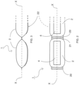
figures 7A and 7B respectively show a cross-sectional view of the limb portion at a blood vessel on which the device offigure 1 is applied, and a cross-sectional view of the application of a containment bandage on said device. - The idea underlying the present invention is to standardise a method for the treatment of varices and capillaries so as to facilitate and enhance the precision of the task of the medical staff, under any pathological condition, with only one device. To this end, it was decided to develop a device comprising at least one tubular element adapted to be pressurized and provided with at least one portion of the outer surface coated by an adhesive layer for contact with the skin of a patient so that it can be precisely applied on the treated area and remain thereon. Suitably repeatable, this element is then kept active by compression means.
- In particular, the device of the invention is indicated with
reference numeral 1 infigure 1 . It comprises at least one functional tubular orsac element 2 made of inflatable plastic adapted to transfer the pressure exerted from the external on a well-defined area of a limb of a patient (see for examplefigures 1 ,3 and4 ). - The
tubular element 2 is a sort of inflatable sac extending along a longitudinal axis X-X from a first 20 to asecond end 21. Both ends are sealed or can be sealed hermetically so that it can contain a pressurised fluid or gas and, therefore, act as a compressible cushion to (evenly) transfer pressure at the area where it is applied. Preferably, the element is filled with an inert gas, for example air, with a pressure generally such to fully expand the internal space and cause the full tension of the walls of the element. In any case, the amount of fluid or gas and the pressure can be adjusted according to particular needs or preferences, for example taking into account the body mass overlying the area to be treated. - According to an embodiment, the device of the invention comprises a plurality of
tubular elements 2 joined together at the respective first 20 and second 21 end so as to form a sort ofchain 22, as shown in thefigures 2 and 3 . This chain may derive from an individual long tubular element which is filled with a fluid to obtain the inflation thereof and subsequently transversely split in individual separate elements with desired length by welding the inner surfaces. Otherwise, individual inflatedtubular elements 2 may be joined together using glue, connecting means such as Velcro, snap fasteners, buttons and corresponding holes, hooks and corresponding holes or the like, or simply arranged adjacent to each other. - Advantageously, the
tubular element 2 mentioned above comprises a portion of its outer surface coated by a layer of glue 3 (figures 4 and5 ), preferably biocompatible and anergic. This layer ofglue 3 is in turn covered by aprotective film 4 made of paper, plasticised paper or plastic, which can be removed to apply the element on the limb of a patient. The layer ofglue 3 preferably extends along the entire axis X-X of theelement 2 from the first 20 to the second 21 end on its central portion. Alternatively, the glue may involve up to half of the circumferential surface of the tubular element, or it may be distributed with transversal strips. - The
phlebological device 1 also comprises compression means 5 (figures 6 and7 ) for saidtubular element 2 which can be applied on its outer surface opposite to the surface coated by theadhesive layer 3. These means may be a bandage or gauze which is manually wrapped with various layers by a single strip of fabric exerting the pressure required to block the terminal end of the strip with conventional stops such as adhesive tapes or elastic hooks. Alternatively, said means may be a conventional strip or elastic stocking to be worn around the limb portion on which thetubular element 2 mentioned above is applied being superimposed thereto to exert the required pressure. - In the light of the above, it can be easily deduced that the phlebological device of the invention allows an applicability that is simple, quick, highly efficient and highly versatile given that it is standardised. As a matter of fact, as shown in the
figures 5-7 , the application of thedevice 1 provides for a few steps which essentially comprise the positioning of one or moretubular elements 2 at the point for applying pressure on the limb A of a patient, as shown infigure 6 representing a portion of a lower limb of a patient, after removing theprotective film 4 of the layer ofglue 3 as shown infigure 5 . In particular, as shown by the enlargement offigures 7A and 7B , atubular element 2 suitably inflated according to the recommendations of the physician depending on the conditions of the patient, is adhered to the dermis D for example of a section of the venous vessel V, such as the saphenous vein. Thanks to the adhesive layer, thetubular element 2 remains in position advantageously allowing the operator to handle a compression means, such as an elastic stocking or a bandage, without any concern whatsoever on an easy shifting of the tubular element. Being thus free, the operator may proceed without further aid with the excellent result for applying a pre-established and controlled/controllable pressure due to the characteristics of the inflatedtubular element 2 mentioned above (figure 7B ). - Therefore, the vein portion affected by the pressure will be effectively crushed specifically due to the transfer of the pressure exerted by the compression means 5 by the
tubular element 2. - In the light of the above, it is clear that the drawbacks related to systems and devices of the prior art outlined above have been overcome. In particular, the invention allows to avoid hand-made pressure transfer elements that are not easy to control, repeatable with the same characteristics, therefore which can be standardised. Furthermore, the invention allowed to eliminate the potential unwanted shifting from the required point of application.
- By contrast, the phlebological device of the invention is perfectly controllable, it can be made up of multiple elements with characteristics which can be standardised, on the one hand, and which can be adjusted depending on the specific needs, on the other hand. As a matter of fact, should the device comprise a plurality of tubular elements extending in sections of a limb of a patient with different anatomical characteristics (greater thickness of the adipose tissue under the dermis, thicker muscle layer, etc.), the different tubular elements may be inflated at different pressure values for an almost perfect adaptation to the anatomy of the person.
- In this regard, it should be observed that according to a preferred embodiment of the invention, the
tubular elements 2 may be provided with valves (not shown) for the filling thereof as needed and according to the physician's recommendations. Such valves may be conventional check valves, that is that allow the inflow of air and block the outflow thereof, unless the walls of the air inflow hole are suitably squeezed. - Therefore, according to a further object of the present invention, the
phlebological device 1 comprises an assembly kit provided with a singletubular element 2 made of inflatable plastic like the one described above and which extends for a length of a few metres and which can be cut depending on the needs, compression means 6, inflation means (not shown), and an apparatus (not shown) for the transversal sealing of sections of said element. The element may be provided with the valves mentioned above distributed at pre-determined distances along the longitudinal axis thereof and, obviously, on the wall opposite to the one carrying theadhesive layer 3 mentioned above. The sealing apparatus may be a conventional commercial equipment such as for example one provided with a plate that can be heated which melts the two transversal opposite strips of the tube of theelement 2 through heat. The inflation means may be manual or electrical air pumps of the commercial type. - The phlebological device of the present invention may be subjected - by the person skilled in the art - to numerous modifications and variants but without departing from the scope of protection of the attached claims.
- For example, the materials used for the tubular element may be conventional anergic plastics such as polyethylene. The glues of the adhesive layer may be biocompatible glue, also anergic.
- The dimensions of the tubular element may vary depending on the specific needs or preferences, same case applying to those of the compression means. In particular, the phlebological device represents an eccentric body, once the compression means are applied around the limb of the patient, given that it is only there that there is a different pressure value considering the circumference of the limb on which the compression means are wound.
- Furthermore, the individual tubular element may be produced with any desired size and, preferably, for the treatment of telangiectasias and reticular veins the dimensions in the swollen conditions are 15×70 mm and for the collateral saphenous veins and the great and small saphenous veins measure 35×90 mm.
Claims (10)
- Phlebological device (1) comprising at least one tubular element (2) adapted to be pressurized and provided with at least one outer portion coated by an adhesive layer (3) for contact with the skin of a patient, said adhesive layer being covered by a removable protective strip (4), and further comprising compression means (5) for said element applicable onto the outer surface of the device, opposed to said surface coated by the adhesive layer.
- Phlebological device (1) according to claim 1, wherein said tubular element (2) is made of sealable inflatable anergic plastic and it extends along a rectilinear axis (X-X) between a first (29) and a second (21) sealable end for containing a pressurized fluid.
- Phlebological device (1) according to claim 1 or 2, wherein said tubular element (2) is formed by a plurality of single tubular elements (2) connected each other at said first (20) and second end (21) so as to form a chain (22).
- Phlebological device (1) according to any one of claims 1 to 3, wherein said tubular elements (2) are connected by means of connecting means comprising glue for joining two opposite inner strips of the tube, welding of said two opposite inner strips of the tube, or Velcro, snap fasteners, buttons and corresponding holes, hooks and corresponding holes.
- Phlebological device (1) according to any one of claims 2 to 4, wherein said adhesive layer (3) is a strip of biocompatible and anergic glue extending along said axis (X-X) of the tubular element (2) from its first (20) to the second (21) end and on its central portion.
- Phlebological device (1) according to any one of claims 2 to 4, wherein said adhesive layer (3) is at least one strip of biocompatible and anergic glue extending transversal to said axis (X-X) up to half of its surface.
- Phlebological device (1) according to any one of claims 1 to 6, wherein said compression means (5) of said tubular element (2) are applicable onto its outer surface opposite to the surface coated by said adhesive layer (3) and comprise a bandage, gauze, compression-elastic band or stockings.
- Phlebological device (1) according to any one of claims 1 to 7, wherein said tubular element (2) comprises at least one check valve for its controlled and adjustable inflation.
- Phlebological kit comprising at least one tubular element (2) according to claim 1 made of inflatable plastic extending along a longitudinal axis (X-X), compression means (6) of said tubular element when it is inflated, means for inflating said tubular element, and an apparatus for sealing said tubular element.
- Phlebological kit according to claim 9, wherein said inflation means are a manual or electric air pump, said sealing apparatus comprises a plate that can be heated for fusing two opposite strips of the tubular element (2).
Applications Claiming Priority (1)
| Application Number | Priority Date | Filing Date | Title |
|---|---|---|---|
| IT102023000011667A IT202300011667A1 (en) | 2023-06-07 | 2023-06-07 | PHLEBOLOGICAL DEVICE |
Publications (2)
| Publication Number | Publication Date |
|---|---|
| EP4473919A1 true EP4473919A1 (en) | 2024-12-11 |
| EP4473919B1 EP4473919B1 (en) | 2026-02-11 |
Family
ID=87801351
Family Applications (1)
| Application Number | Title | Priority Date | Filing Date |
|---|---|---|---|
| EP24180423.6A Active EP4473919B1 (en) | 2023-06-07 | 2024-06-06 | Phlebological device |
Country Status (2)
| Country | Link |
|---|---|
| EP (1) | EP4473919B1 (en) |
| IT (1) | IT202300011667A1 (en) |
Citations (3)
| Publication number | Priority date | Publication date | Assignee | Title |
|---|---|---|---|---|
| US4224945A (en) * | 1978-08-30 | 1980-09-30 | Jonathan Cohen | Inflatable expansible surgical pressure dressing |
| US20140163606A1 (en) * | 2011-06-09 | 2014-06-12 | Angioclinic Ag | Adhesive patch or bandage for use in treating blood vessel diseases |
| CN215273103U (en) * | 2020-12-22 | 2021-12-24 | 上海中医药大学附属曙光医院 | Arteriovenous internal fistula puncture site hemostasis device |
-
2023
- 2023-06-07 IT IT102023000011667A patent/IT202300011667A1/en unknown
-
2024
- 2024-06-06 EP EP24180423.6A patent/EP4473919B1/en active Active
Patent Citations (3)
| Publication number | Priority date | Publication date | Assignee | Title |
|---|---|---|---|---|
| US4224945A (en) * | 1978-08-30 | 1980-09-30 | Jonathan Cohen | Inflatable expansible surgical pressure dressing |
| US20140163606A1 (en) * | 2011-06-09 | 2014-06-12 | Angioclinic Ag | Adhesive patch or bandage for use in treating blood vessel diseases |
| CN215273103U (en) * | 2020-12-22 | 2021-12-24 | 上海中医药大学附属曙光医院 | Arteriovenous internal fistula puncture site hemostasis device |
Also Published As
| Publication number | Publication date |
|---|---|
| EP4473919B1 (en) | 2026-02-11 |
| IT202300011667A1 (en) | 2024-12-07 |
Similar Documents
| Publication | Publication Date | Title |
|---|---|---|
| US7276037B2 (en) | Compression apparatus for applying localized pressure to the venous system of the leg | |
| US7559908B2 (en) | Compression apparatus for applying localized pressure to a wound or ulcer | |
| EP2219576B1 (en) | Assembly for treating venous ulcers and wounds | |
| US4846160A (en) | Method of promoting circulation in the hand | |
| US5968072A (en) | Method and apparatus for cold compression treatment of wounds | |
| JP2690780B2 (en) | Medical instruments for hands | |
| US20030191420A1 (en) | Therapeutic limb covering using hydrostatic pressure | |
| US20160174952A1 (en) | System and method for achieving patent hemostasis in arteries | |
| US20040193084A1 (en) | Vein compressor device | |
| US4566436A (en) | Method for applying and/or keeping an ischaemic area during surgery on the limbs | |
| WO1998009596A1 (en) | System and method for improving vascular blood flow | |
| US7854748B2 (en) | Device and method for excluding blood out of a limb | |
| AU2009217447A1 (en) | Compression device with removable portion | |
| CN106102670A (en) | Adhesive film bandages for medical compression | |
| EP2057974B1 (en) | Medical device for pressurizing limbs and trunk | |
| EP4473919A1 (en) | Phlebological device | |
| JP2022522150A (en) | Hemostasis band with improved edge design | |
| CN117084745B (en) | Method for forming a dressing for applying pressure to stop bleeding on fingers or toes and the dressing | |
| US10172743B2 (en) | Compression element | |
| EP2968020B1 (en) | Compression element | |
| US20200000622A1 (en) | A Kit And Therapeutic Pressure Assembly With Patches For Applying Pressure To A Limb Or Other Body Part | |
| RU229617U1 (en) | Hemostatic device | |
| RU227998U1 (en) | MECHANICAL HEMOSTATIC DEVICE | |
| US20230256156A1 (en) | Decompression wrap | |
| EP0228768A2 (en) | Medical appliance for the hand |
Legal Events
| Date | Code | Title | Description |
|---|---|---|---|
| PUAI | Public reference made under article 153(3) epc to a published international application that has entered the european phase |
Free format text: ORIGINAL CODE: 0009012 |
|
| STAA | Information on the status of an ep patent application or granted ep patent |
Free format text: STATUS: THE APPLICATION HAS BEEN PUBLISHED |
|
| AK | Designated contracting states |
Kind code of ref document: A1 Designated state(s): AL AT BE BG CH CY CZ DE DK EE ES FI FR GB GR HR HU IE IS IT LI LT LU LV MC ME MK MT NL NO PL PT RO RS SE SI SK SM TR |
|
| STAA | Information on the status of an ep patent application or granted ep patent |
Free format text: STATUS: REQUEST FOR EXAMINATION WAS MADE |
|
| 17P | Request for examination filed |
Effective date: 20250606 |
|
| GRAP | Despatch of communication of intention to grant a patent |
Free format text: ORIGINAL CODE: EPIDOSNIGR1 |
|
| STAA | Information on the status of an ep patent application or granted ep patent |
Free format text: STATUS: GRANT OF PATENT IS INTENDED |
|
| RIC1 | Information provided on ipc code assigned before grant |
Ipc: A61B 17/132 20060101AFI20251001BHEP Ipc: A61B 17/00 20060101ALN20251001BHEP |
|
| INTG | Intention to grant announced |
Effective date: 20251014 |
|
| GRAS | Grant fee paid |
Free format text: ORIGINAL CODE: EPIDOSNIGR3 |
|
| GRAA | (expected) grant |
Free format text: ORIGINAL CODE: 0009210 |
|
| STAA | Information on the status of an ep patent application or granted ep patent |
Free format text: STATUS: THE PATENT HAS BEEN GRANTED |
|
| AK | Designated contracting states |
Kind code of ref document: B1 Designated state(s): AL AT BE BG CH CY CZ DE DK EE ES FI FR GB GR HR HU IE IS IT LI LT LU LV MC ME MK MT NL NO PL PT RO RS SE SI SK SM TR |
|
| REG | Reference to a national code |
Ref country code: CH Ref legal event code: F10 Free format text: ST27 STATUS EVENT CODE: U-0-0-F10-F00 (AS PROVIDED BY THE NATIONAL OFFICE) Effective date: 20260211 Ref country code: GB Ref legal event code: FG4D |
|
| REG | Reference to a national code |
Ref country code: DE Ref legal event code: R096 Ref document number: 602024002480 Country of ref document: DE |
|
| REG | Reference to a national code |
Ref country code: IE Ref legal event code: FG4D |